1
SM-Z-89-37
Double-Density Disk Controller
Service Manual
2NI'N
~
data
systems
581;-8
ZENITH DATA SYSTEMS
SAINT JOSEPH, MICHIGAN 49085
Copyright © 1982
Zenith Data Systems
1).11 Rights Reserved
Printed in the United States of America
111.....
DOUBLE-DENSITY DISK CONTROLLER
Table of Contents
SPECIFICATIONS
RECONFIGURATION
'fo Change the Internal Drive
To Rearrange the Drive Numbers
Programming Modules
1-1
2-1
" 2-1
2-3
2-7
CIRCUIT DESCRIPTION
3-1
Control Lines (P2)
3-2
Ul Data Buffer and U7B Buffer Direction Control. . . . . . . . . . . . . . . . . . .. 3-2
U2, U3, U4 Interrupt Control
3-2
U5 Open Collector NAND Gates
3-2
U6 Control Decoder and Inverter . . . . . . . . . . . . . . . . . . . . . . . . . . . . . . . . . .. 3-3
U7A Address Control Latch
3-3
U8A Reset Pulse Latch . . . . . . . . . . . . . . . . . . . . . . . . . . . . . . . . . . . . . . . . . . .. 3-3
,
,
,
,
3-3
U8B Head Load Delay
3-3
U9 and Ul0 Disk Controller Clock
Ull Interface Control Latch
,
3-3
U13 Input Signal Multiplexer. . . . . . . . . . . . . . . . . . . . . . . . . . . . . . . . . . . . .. 3-3
U14 Raw Read Latch
3-4
U15 Drive Buffer
3-4
U16, U17, U18, Ql, and Q2 Phase Lock Loop
3-4
Tracking and Precompensation
U19, U20, U21, and U22 Disk Drive Interface
3-4
U23 Voltage Regulator
3-4
Block Diagram
Fold-out from page 4-1
DIAGNOSTIC ROUTINE
To Rearrange the Drive Numbers
Starting the Diagnostic Programs
Disk Controller Checkout
Disk Controller Checkout Error Messaees
4-1
4-2
" 4-6
4-8
4-10
i, i
....,
- - -.....1111
DOU8LE·DEItIITY DISK CONTROlLER
General Drive/Controller Diagnostic
Initiating the General Drive/Controller Diagnostic
Available Tests and Options
F.,...Format Disk Surface ...........................•...............
T-Drive Speed
,
,
D-General Drive Checkout ................................•.... ,.
M-Media Check
S-Seek Time
A-Align
"
"
U-Switch
E-Exit ...................................................•......
4-11
4-11
4-12
4-12
4·13
4-14
4-15
4-15
4-16
4-17
4-17
SERVICE
,
Recalibration
VCO Bias Adjustment . . . . . . . . . . . . . . . . . . . . . . . . . . . . . . . . . . . . . . . . . . . ..
VCO Center Frequency Adjustment
(with Frequency Counter)
VCO Center Frequency Adjustment
(with Oscilloscope)
Precomposition Adjustment
In Case of Difficulty
,..................
Decimal to Octal to Hex to ASCII Conversion
,
,
5-1
5-1
5.2
REPLACEMENT PARTS LIST
6-1
'"
SEMICONDUCTOR IDENTIFICATION CHART
5-4
5-4
5-5
5·6
7-1
CIRCUIT BOARD X-RAY VIEW
SCHEMATIC
5-2
,. 8-1
" .,
Fold-in
IV IL'
DOUBLE-DENSITY DISK CONTROLLER
u
u
u
DOUBLE-DENSITY DISK CONTROLLER
Specifications
The Z-89-37 Double-Density Disk Controller interfaces the Z-89/90 Computer with the
Z-37 Floppy Disk.* The Controller will read and write to drives using SOFT-SECTORED
DISKS as follows:
Double-Sided (H-17-4 drives):
96 tracks per inch
80 tracks per side
Single or double density
Single-Sided (H-17-1 drives):
48 tracks per inch
40 tracks
Single or double density
Required software is:
HDOS version 2.0 modified (or higher)
or
CP/M version 2.2.03 (or higher)
NOTICE: If a Z-87 Floppy Disk System is to be used with a Z-89 or 2-90 Computer,
proceed to "Reconfiguration" and, if necessary, reprogram the drives in the Z-87 Floppy
Disk.
'Cassette operation is not supported.
11,. t
1-2 1
DOUILE..DENSITY DISK CONTROLLER
u
12.,1
DOUBLE-DENSITY DISK CONTROLLER
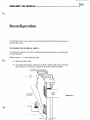
Reconfiguration
To reconfigure the system, choose the instructions below that fit the application and
perform those steps.
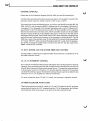
TO CHANGE THE INTERNAL DRIVE...
To change the internal drive from handling hard-sectored diskettes to handling softsectored diskettes:
Refer to Figure 2-1 for the following steps.
•
Open the cabinet shell.
•
Unplug the short floppy cable from the H-88-1 Floppy Disk I/O circuit board
and reconnect it to the top connector of the Z-89-37 Disk Controller.
Figure 2-1
2-21_--
- - - - - - - - - DOUBLE-DENSITY DISK CONTROLLER
•
Set switch SW501, section 4 (on the CPU logic circuit board) to 1. The Z-37
connected drives are now the primary drives and they are now numbered as
shown in Figure 2-3 on Page 2-3. (NOTE: IF YOU REMOVE THE UNUSED
H-88-1 FLOPPY DISK I/O CIRCUIT BOARD, YOU MUST CONNECT A 4700
OHM RESISTOR TO PLUG P512 BETWEEN PINS 1 AND 12. SEE FIGURE 2-2.)
Figure 2-2
DOUBLE-DENSITY DISK CONTROLLER
_ _ _ _ _ _ _ _ _1. 2:-3
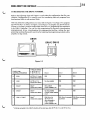
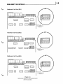
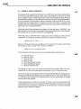
TO REARRANGE THE DRIVE NUMBERS...
Refer to the following chart and Figure 2-3, and select the configuration that fits your
situation. Configuration E is normally used for transferring data and programs from
hard-sectored disks to soft-sectored disks.
After you select the configuration you want, refer to Figure 2-4 on Page 2-4 to program
any 48 TPI (H-17-1) drives, or Figure 2-5 on Page 2-5 to program any 96 TPI drives.
[Figure 2-6 on Page 2-6 shows single-sided drives (H-17-1) programmed for connection
to an H-88-1 Controller.] You can do this programming by physically interchanging
preprogrammed drives, interchanging the programming modules, cutting the programming modules (if presently uncut); or by replacing the programming module with a
properly set dip switch.
DRIVE
~
lE:Jbm
DRIVE DRIVE
1
2
~
~
W
'-J
Figure 2-3
FLOPPY DISK
CONTROLLER BOARD(S)
TYPES OF DRIVES:
• 48 TPI (H-17-1)
• 96 TPI (H-17-4)
Drive 0
Drive 1
Drive 2
A
H-88-1
48 TPI (H-17-1) only.
Internal drive present
DS3
DS2
DS1
B
H-88-1
48 TPI (H-17-1)
Internal drive absent
No drive installed
DS3
DS2
C
Z-89-37
Either*
Internal drive present
DS1 (Z-89-37
jumper installed at J4)
DS2
DS3
D
Z-89-37
Either *
Internal drive absent
DS1
No drive jnstalled
(Z-89-37 jumper installed
at J7)
DS2
E
H-88-1 & Z-89-37
Either*
Internal drive present
DS3 [Drive 0 is
48 TPI (H-17-1)
drive connected to
H-88-1. Z-89-37
jumber installed at J6.]
DS1 (Drive 0 connected
to Z-89-37)
* All drives connected to the Z-89-37 should be of the same type, either 48 TPI (H-17-1) or 96 TPI (H-17-4).
DS2 (Drive COnnElcted
Z-89-37)
2-4 IL
DOUBLE-DENSITY DISK CONTROLLER
u
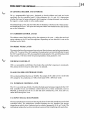
HARDWARE UNIT ZERO (DS1)
HARDWARE UNIT ONE (DS2)
[,,.,.J
~ ~Ir--_~
CUT
[~~~,~J ~I,n,~"l
PROGRAMMING
MODULE
HARDWARE UNIT TWO (DS3)
INSET
B
L
ODD
H~MSSSH
M K
X3 2 1 S
~
'----~}
NOTE: CONNECTOR PINS
AT HM MUST REMAIN
OPEN lUNSHORTENEDl.
Figure 2-4
Single-sided drives (H-17-1) programmed for
Z-89-37 Controller.
u
----l12.. 5
DOUBLE-DENSITY DISK CONTROLLER
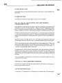
Hardware Unit Zero (OS1)
~,.,-'+'.'.1.i ('.1-1.'.1.J
PROGRAMM I NG
MODULE
Hardware Unit One (052)
f,·,-'·'·'·l-l. ~
('.1'1-'-'-1-~
PROGRAMM I NG
MODULE
Hardware Unit Two (053)
~'.'-'-'-'.1-1-i ['.l.l.,.,.J
PROGRAMM I NG
MODULE
Figure 2-5
Double-sided drives (H-17·4) programmed for
Z·89-37 Controller.
2-6 1L-
DOUBLE-DENSITY DISK CONTROLLER
u
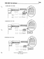
HARDWARE UNIT ZERO
I
I
HARDWARE UNIT ONE
,
)
I.. ".J~
CUT
I~~~,~J ul~
u
",1_ _
---.
PROGRAMMING
MODULE
HARDWARE UNIT TWO
[,~-J
Figure 2-6
Single-sided drives (H-17-1) programmed for
H-88-1 Controller.
u
DOUBLE-DENSITY DISK CONTROLLER
_ _ _ _ _ _ _ _ _ _12:-7
,
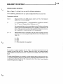
PROGRAMMING MODULES
Refer to Figure 2-7 on Page 2-8 as you read the following information.
Use the following information for any special configurations that you may want.
Programming modules:
J1 & J2
Select port 170 or 174. (Both jumpers must be at 170, or both jumpers
must be at 174. 170 is normal.)
J3
o = No precompensation; 1 = precompensation. (0 position is normal.)
Use "0" only on Wangco drives. Otherwise, use "1."
We recommend that you do not use both 48 and 96 TPI drives in the same
system, since the precompensation will be wrong for at least one of the
drives. This can result in reduced data reliability. When precompensation is selected, it is factory pre-set to 300 nanoseconds.
J4- J7
Selects which drive is connected to plug P3. (Drive numbers are determined by how the drive programming modules are cut. See Figure 2-4 on
Page 2-4).
J4
J5
J6
J7
DS1
DS2
= DS3
= DS4 (presently not supported)
=
=
Z-89-47
For a system to operate properly with the Z-89-3 7, the Z-89-47 I/O board should be
installed at plugs P506 and P512. However, before the Z-89-47 will operate properly
when plugged into plugs P506 and P512, a resistor must be added to the Z-89-47 circuit
board.
To make the modification, use a 4700 il, 1/4-watt resistor (yellow-violet-red), HE 6-47212; and slide a length of sleeving over the resistor. Solder the resistor between pins 1 and
12 of plug P2 on the foil side (not the component side) of the Z-89-47 circuit board as
shown in Figure 2-2 on Page 2-2.
2-8 ,~
DOUBLE-DENSITY DISK CONTROLLER
u
u
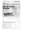
Figure 2·7
Z-89-37 Double-Density Disk Controller Board.
Part number HE 181-3614.
DOUBLE-DENSITY DISK CONTROLLER
Circuit Description
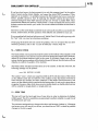
Refer to the Block Diagram (fold-out from Page 4-1) while you read the following Circuit
Descriptions.
The board's function is to translate the instructions of the processor to the disk drives.
Assume that the processor wants to write on disk drive number one. First, the processor
sends the proper enabling and control signals over the control lines. These signals are
made compatible with the 1797 disk controller by the control decoder and inverter. The
controller then blocks all interrupts to the processor (except its own) by sending a "block
interrupts" signal to the interrupt control ICs. This prevents another peripheral from
interfering with the transfer of data between the processor and the disk drive. The
controller also signals the buffer direction control IC to allow input from the processor to
pass through the data buffer to the controller.
The interface control latch then starts the motor of disk drive number one by translating
the drive control signals from the processor. The data from the processor is now sent over
the data bus, through the 1797, the support logic and disk interface logic, and to drive
number one over the disk serial data line (the support logic and disk interface logic help
the 1797 disk controller communicate with the drive electronics). The support logic
consists ofICs uaB, U13, U14A, and U15. The interface logic consists ofU19, U20, U21,
and U22. These are all explained below.
The read process is similar to the write process. First, the processor sends the proper
enabling and control signals over the control lines, just as before (of course this time the
signals enable the disk controller board to read instead of write). The signals are made
compatible with the 1797 disk controller IC by the control decoder and inverter. The
controller again blocks all interrupts to the processor (except its own) by sending a
"block interrupts" signal to the interrupt control ICs, preventing another peripheral
from interfering with the transfer of data. The controller also signals the buffer direction
control IC to allow output to the processor to pass through the data buffer from the
controller. The interface control latch then starts the motor of disk drive number one by
translating the drive control signals from the processor. The data from the disk is now
sent over the drive serial line, through the disk interface logic, the support logic and the
1797 disk controller, and to the processor via the data buffer and data bus.
The phase lock loop (PLL), which is part of the support logic, and the variable control
oscillator (VCO) together track the frequency of data read from the disk. This tracking
generates a read clock (RCLK) signal that tells the disk controller how fast to read the
data. (The frequency of the incoming read data changes due to variations in the rotating
speed of the disk and the position of the data on the disk.)
--'1 3:- 1
3-2 1L...
DOUBLE-DENSITY DISK CONTROLLER
CONTROL LINES (P2)
Please refer to the Schematic Diagram (fold-in) while you read this description.
All of the disk control lines from the processor are input to U6 via plug P2, except for the
processor system clock line, which is input to U5A via pin 13 of P2.
The control lines consist of address lines AO, Ai, and A2, read line RD, write line WR, I/O
DISK, I/O FLPY, and the reset line RESET.lAddress line A2 is inverted by U5Bwhen J1A
is jumpered. J1A is jumpered in the standard operating mode, as is J2A. Otherwise A2
goes directly to U6.) The address lines access the 1797 disk controller's (U12) registers.
The read and write lines, low when active, tell the controller which way the data buffer
direction control should be set and whether the read or write lines to the disk driver
electronics should be used. The I/O DISK and I/O FLPY lines enable the controller board
and tell the board which block of memory in the processor is used for disk I/O. The I/O
DISK line is used in the standard mode. In this mode the I/O memory block base address
is 170 octaLI/O FLPY, when connected through jumper J2B, is used when the programmer wishes to designate another block of memory for disk I/O. The last control line,
RESET, initializes the controller.
Ut DATA BUFFER AND U7B BUFFER DIRECTION CONTROL
The data buffer is a bidirectional, eight-bit buffer whose direction is controlled by U7B,
the buffer direction control.
U2, U3, U4 INTERRUPT CONTROL
ICs U2 and U4 are taken from the processor CPU board. They are the processor's interrupt
channels. They are relocated onto the disk controller board so that the disk controller can
block all other interrupts to the processor except its own. U3 screens the interrupt signals
to the processor under Ull's direction. U3 turns the eight-bit interrupt to the processor
into three-bit interrupt signals. The three-bit interrupt becomes part of an eight-bit data
instruction via U2. U2 supplies five other hard wired bits.
For more information about U2 and U4, consult your processor's operation manual.
Us OPEN COLLECTOR NAND GATES
There are four gates used on the IC, called A, B, C, and D. The gates invert the: processor
system clock for use by the 1797, interrupt from the 1797 to the processor, and addressing information from the processor to all parts of the disk controller board.
u
DOUBLE-DENSITY DISK CONTROLLER
U6 CONTROL DECODER AND INVERTER
U6 is a programmable logic array, designed to decode address and read and write
conditions for the controller board. Using addresses AO, Al, and A2 it determines
whether the board is being addressed, which register is being addressed, and whether
the signal is a read enable or write enable signal.
The internal logic of U6, and most other ICs on the board, is shown in the "Semiconductor Identification Chart." All inputs and outputs of the IC are marked on the chart as they
are on the Schematic.
U7A ADDRESS CONTROL LATCH
The address control latch helps call up the registers in the 1797 - either the track and
sector registers or the CiS and data registers, depending on how data bit 0 is set on the
interface control latch.
U8A RESET PULSE LATCH
The reset pulse from the processor does not meet the minimum reset pulse requirements
ofthe 1797. To correct this, UBA lengthens the reset pulse to an interval sufficient to meet
the 1797's specifications. UBA also supplies the reset signal to U16, part of the phase lock
loop circuitry. U16 then resets the precompensation clock generator, UIB.
U8B HEAD LOAD DELAY
UBB is a monostable multivibrator that delays the controller's response to commands.
This allows the drive head to settle after it is selected.
U9 AND Ul0 DISK CONTROLLER CLOCK
U9 is a clock oscillator that runs at 16 MHz. The output of U9 is fed to UI0. UI0 divides
U9's output by 16, producing a 1 MHz clock signal with a 50% duty cycle.
Ull INTERFACE CONTROL LATCH
The Ull is an octal type-D latch. It latches the high speed processor signals for the 1797
disk controller (U12) and interface control latch (Ull). Some commands, such as
MOTOR, go directly from the Ull to the disk drive interface ICs, U19, U20, and U21,
rather than through the 1797.
U13 INPUT SIGNAL MULTIPLEXER
This IC multiplexes the control and data signals from the two disk interfaces into the disk
controller board. The multiplexer switches between the two interface line groups,
depending on which drive is selected and on which of jumpers J4, J5, J6, or J7 is set. The
multiplexer isolates the two drive interfaces to prevent their interfering with each other.
13,.3
3-4 1l....
DOUBLE-DENSITY DISK CONTROLLER
U14 RAW READ LATCH
U14lengthens the raw read pulse from the disk drive electronics to a size readable by the
1797 (U12).
U15 DRIVE BUFFER
U15 buffers the control and data signals to the two drive interfaces.
U16, U17, U18, Q1, AND Q2 PHASE LOCK LOOP TRACKING
AND PRECOMPENSAnON
U16 supplies U17 with either a pull-up (PU) or pull-down (PD) signal. This signal is then
filtered by C29 and R13 and then called FC - frequency control. Voltage control oscillator U1? changes its frequency, higher with a PU signal and lower with a PD signal. The
change in frequency produces a corresponding change in rotational speed of the disk.
Variable resistor R10 biases the PU and PD output at 1.4 volts (this means that PU/PD are
1.4 volts when the phase lock is inactive). This allows the phase lock to more quickly
lock on to the data being read. Variable resistor R17 adjusts the VCO's center frequency to
2 MHz.
The VCO's output is divided down by U16. This signal then becomes the read clock
(RCLK) signal, which is used by the 1797 to separate disk data and disk clock signals.
The U16 also strobes the early and late signals for data precompensation. These internally latched signals determine which phase of a four-phase clock generator, U18, will
be used for the precompensation process. All phases are identical in pulse width (+ or
-50 nsec). The phase delay time is set by R20.
Precompensation, used for 80-track double-density disk write operations, places data
properly on the disk so that it can be read back with minimum error. (Error may be
introduced by the shifting of old data as new data is written - as data is written, data
adjacent to the new data is shifted over because of the nature of the magnetic medium of
the disk.)
U18, precompensation clock generator, provides the clock signals needed for precompensation of write signals.
U19, U20, U21, AND U22 DISK DRIVE INTERFACE
The disk drive interface lCs buffer all signals to and from the disk drive electronics by
means of open collector drivers.
U23 VOLTAGE REGULATOR
U23 supplies +5 V regulated to U1?, isolating the U17 from theZ-89 +5 V power supply.
u
DOUBLE-DENSITY DISK CONTROLLER
----'1 4-1
P2
p------~-------------~-------------------------------------------------~-----------------------------------------------,
.
-
-.
•
I
,I
DATAB4S PI;
10-9)
__
.
Diagnostic Routine
I
SYSTEM
INTERRUPT
SIGNALS
The diagnostic and conversion diskette supplied with the disk controller allows you to
"check out" or troubleshoot your disk system and move software from the hard-sectored
diskettes used by the single-density controller to the soft-sectored diskettes used by the
double-density controller, Z-89-37.
I
,,I
!?I
Pi
To perform the diagnostics, you will need at least two blank, 5.25-inch, soft-sectored
diskettes. It does not matter whether these soft-sectored diskettes are single or double
density, nor whether they are signal or double sided.
-.
h
.-
h
--
RCLK
-
.-
INTERRUPT
CONTROL
1INTERRUPT
BLOCKING)
lU2.3.41
DISK CONTROLLER
INTERRUPT SIGNALS
--
-
SUPPORT
LOGIC
IUI6. U181
r-
-----
WD
RD
-
~
'"
The diagnostic routine is supplied on a 5.25-inch bootable diskette labeled "Soft Sectored." Customers also receive a diskette labeled "Hard Sectored." The only difference
between these diskettes is the type of media and the addition of the hard-sectored to
soft-sectored conversion routine on the hard-sectored diskette. Otherwise, the programs
that the diskettes contain are identical. You can use either diskette to perform the
diagnostics, but be sure to use the diskette labeled "Soft Sectored" only in disk drives
that are connected to the Z-89-37 Controller. You can use the hard-sectored diskette in an
H-17, H-77, or Z-87 with an H-88-1 (hard-sectored) floppy disk interface.
Those who have single-sided disk drives and are uncertain whether they have installed
the Controller or disk drives correctly, should boot up the diskette labeled "Hard
Sectored" in a hard-sectored disk drive connected to an H-88-1, single-density, floppy
disk controller, and then run the diagnostics from the hard-sectored diskette.
-
.DATA
BUFFER
( U1 )
BUFFER
DIRECTION
CONTROL
lU7B)
--1
l-.
,-
I
I
I
!
-,
,,
!,, ,,
--'.
;;
j~
I
I
I
I
I
I
DISK
INTERFACE
( UI9.20 •
21,22 )
P3
INTERNAL·DRIVE
SERIAL LINES,
CONTROL LINES
,r
VCO
(U17l
INTERFACE
CONTROL
LATCH
lUll )
DISK
CONTROLLER
-
IUl2)
---r
L------
-
PLL TRACKING
h
CONTROL
LINES !2 i
•
I
--
i
BUS RESET _
---
CONTROL
DECODER,
INVERTER
( U6 )
CLOCK
(lMHz)
,.
_.
--
·i
--
I
I _
lU9.l0)
P4
EXTERNAL DR IVE
> SERIAL LINES,
CONTROL LINES
i I
RESET
RESET
STRETCH
( U8A )
DR IVE SIGNALS (DR IVE , • MOTOR ON/OFF)
-I
--I
,,
,
I
I
RESET
I
I
I
I
--------------------------------------------------------------------------------------------------------------------------BLOCK DIAGRAM
'-
4-2 1L-
DOUBLE"DENSITY DISK CONTROLLER
TO REARRANGE THE DRIVE NUMBERS...
Refer to the following chart and Figure 4-1, and select the configuration that fits your
situation. Configuration E is normally used for transferring data and programs from
hard-sectored disks to soft-sectored disks.
After you select the configuration you want, refer to Figure 4-2 on Page 4-3 to program
any 48 TPI (H-17-1) drives, or Figure 4-3 on Page 4-4 to program any 96 TPI drives.
[Figure 4-4 on Page 4-5 shows single-sided drives (H-17-1) programmed for connection
to an H-88-1 Controller.] You can do this programming by physically interchanging
preprogrammed drives, interchanging the programming modules, cutting the programming modules (if presently uncut); or by replacing the programming module with a
properly set dip switch.
DRIVE
f(1
DRIVE DRIVE
IE:J~\
1
2
~
1m
w
u
Figure 4-1
FLOPPY DISK
CONTROLLER BOARD(S)
TYPES OF DRIVES:
• 48 TPI (H-17-1)
• 96 TPI (H-17-4)
Drive 0
Drive 1
Drive 2
A
H-88-1
48 TPI (H-17-1) only.
Internal drive present
DS3
DS2
DS1
B
H-88-1
48 TPI (H-17-1)
Internal drive absent
No drive installed
DS3
DS2
C
Z-89-37
Either *
Internal drive present
DS1 (Z-89-37
jumper installed at J4)
DS2
DS3
D
Z-89-37
Either *
Internal drive absent
No drive installed
DS1
(Z-89-37 jumper installed
at J7)
DS2
E
H-88-1 & Z-89-37
Either *
Internal drive present
DS3 [Drive 0 is
48 TPI (H-17-1)
drive connected to
H-88-1. Z-89-37
jumper installed at J6.]
DS2 (Drive connected
Z-89-37)
*
DS1 (Drive 0 connected
to Z-89-37)
All drives connected to the Z-89-37 should be of the same type, either 48 TPI (H-17-1) or 96 TPI (H-17-4).
14..3
DOUBLE-DENSITY DISK CONTROLLER
HARDWARE UNIT ZERO (DS1)
HARDWARE UNIT ONE (DS2)
I
.
[::J I
.,.., .. ., .... ..,.,
I
~n
~
I:
:22,
J
CUT
HARDWARE UNIT TWO (DS3)
I
..., 7
. . . . .... -,-.
I
Figure 4-2
Single-sided drives (H-17-i) programmed for
2-89-37 Controller.
4-41
DOUBLE-DENSITY DISK CONTROLLER
HARDWARE UNIT ZERO (051)
n
ll-l-l-l-l-l-l~
1..1-..1
PROGRAMM I NG
MODULE
HARDWARE UNIT ONE (052)
n
ll-l-l-l-l-l-l~
l..1-3
PROGRAMM I NG
MOD ULE
HARDWARE UNIT TWO (053)
~l-l-l-l-l-l-l-~ (l-l-l-l-l-l.~
l,.l-l-l-l-l-l~
(.1- j
PROGRAMM I NG
MODULE
Figure 4-3
Double-sided drives (H-17-4) programmed for
2-89-37 Controller.
_ 14..5
DOUBLE-DENSITY DISK CONTROLLER
HARDWARE UNIT ZERO
t
)
I
I
HARDWARE UNIT ONE
HARDWARE UNIT TWO
Figure 4-4
Single-sided drives (H-17-1) programmed for
H-88-1 Controller.
4-6 1i....-
DOUBLE-DENSITY DISK CONTROLLER
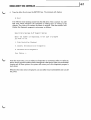
STARTING THE DIAGNOSTIC PROGRAMS
To start the diagnostic programs, boot up the system using either the hard- or softsectored Diagnostic and Conversion Utilities diskette. The part number for the hardsectored diskette is HE 890-156. The part number for the soft-sectored diskette is HE
890-157.
Greater centering accuracy is required when you are using 96 TPI drives. Therefore, it is
imperative that the diskettes you use with your high capacity 5-1/4/1 floppy disk system
have factory-installed mylar hub reinforcing rings. All of the diskettes supplied by
Zenith Data Systems have these rings, as well as Verbatim Datalife diskettes and several
other brands. Do not use any diskettes that do not have these rings.
The following procedure outlines how you should boot up your Computer.
1.
Turn on the power to the Computer. You will hear one or two beeps and see an H: in
the upper left-hand corner of the screen.
2.
Insert the Diagnostic and Conversion Utilities diskette into the drive.
3.
•
Soft-sectored disk goes into drive 0 if you are using only the Z-3 7 (or comparable drives outside your Computer) and no drive in your Computer.
•
Hard-sectored disk goes into drive 2 if you are using the Z-89-37 controller
board with a Z-89 Computer, and drive 2 is connected to a hard-sectored floppy
disk interface (H-88-1). Or, use drive 2 if you are using the H-88-1 interface
board with a Z-90-82 Computer.
•
For all others, refer to "Reconfiguration" on Page 2-1. Define drive 0 and insert
the soft-sectored disk.
Close the drive door.
DOUBLE-DENSITY DISK CONTROLLER
o
4. 'Type the letter B and press the RETURN key. The terminal will display:
H: Boot
You will hear some clicking noises from the disk drive. This is normal. You will
hear such noises whenever the Computer is reading from or writing to the
diskette. The clicks will continue for about 15 seconds. Then the terminal will
display the diagnostic program's main menu, as follows:
Zenith Data Systems Z-37 Support System
Enter the number corresponding to the type of program
you wish to run.
1. Disk Controller Checkout
2. General Drive/Controller Diagnostic
3. Detailed Drive Diagnostic
Your Choice ->
From this main menu, you can select any diagnostic or conversion utility. To select an
option, simply type the number which corresponds to the option. When you are finished
running any of these options, the system will return you to this diagnostic program's
main menu.
Whenever the main menu is displayed, you can safely remove all diskettes and turn off
the power.
1
4--7
4-8
1'--
DOUBLE-DENSITY DISK CONTROLLER
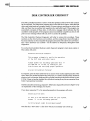
DISK CONTROLLER CHECKOUT
The Disk Controller Checkout is used to verify the operation of the Z-89-3 7 disk controller circuit board. This diagnostic program turns on the disk drive motors, loads the disk
drive read/write heads as a program would if it were trying to read from or write to the
disk, and then tries to position and reposition the read/write head. If the program can
successfully complete all these tests, it will print a message which indicates that the
controller works properly. If the program cannot successfully complete any test, it will
print an error message which tells you how to correct the problem.
The Disk Controller Checkout diagnostic will refer to various drive numbers. These
numbers are the drive hardware unit numbers, and they range from 0 (zero) through 2.
Pay close attention to which number the program associates with a drive as it activates it.
This "drive hardware unit number" will be referred to frequently throughout these
diagnostics.
To run the Disk Controller Checkout, select diagnostic program's main menu option 2.
The system will print:
Detailed Controller Checkout.
This program attempts to verify the operation
of the Z-37 disk controller board.
Please answer the following questions with 'Y'
For YES and 'N' for NO, by looking at your
Disk Drivers and verifying proper operation.
Are All Drive Motors Turning?
To respond, open the doors of the drives on your Z-37(s). On the right-hand side of the
drive, about two inches back from the drive door, is a metal cylinder which measures
about an inch in diameter. Make sure this cylinder is turning in each ofthe drives in your
Z-37(s). It does not matter whether this cylinder is turning in any drives connected to an
H-88-1 hard-sectored controller.
If all the cylinders are turning, respond Y. Otherwise,respondN and turn toPage4-13 for
an explanation of the message you receive.
If you have responded Y to the preceding question, the program will print:
Selecting Drive Zero.
If this is a non-existent drive for your system,
Answer 'Y' to the following question.
Is Drive Select Light On and Head Loaded?
Note that this "Drive Zero" is the drive which you normally use to boot up.
DOUBLE-DENSITY DISK CONTROLLER
To respond to this question, check to make sure the red light on drive 0 is glowing. If it is,
enter Y. Otherwise, enter N and turn to Page 4-13 for an explanation of the message you
receive.
If you have responded Y to the preceding question, the system will print:
Selecting Drive One.
If this is a non-existent drive for your system,
Answer 'y' to the following question.
Is Drive Select Light On and Head Loaded?
To respond to this question, check to make sure the red light on drive 1 is glowing. If it is,
enter Y. Otherwise, enter N and turn to Page 4-13 for an explanation ofthe message you
receive.
The program will continue to activate the drives in this way for drive 2. In general, you
should respond Y if the drive exists and the red light glows, and N only if the drive exists
but the drive light does not come on.
If all the drive motors work properly and the program was able to successfully select all
the drives, the system will now print:
Attempting to verify the operation of the
Head positioning system. Please stand by ...
The program will now attempt to position and reposition the disk drive read/write head,
much as it would as if it were reading from or writing to a diskette. If this test is
successful, the program will print:
Controller appears to be ok. Please continue
on to selection 3 or 4 to make further checks.
If you do not receive this message, refer to the error messages on Page 4-10 for an
explanation of the error message you receive.
14.. 9
4-10 ,'--
DOUBLE-DENSITY DISK CONTROLLER
DISK CONTROLLER CHECKOUT ERROR MESSAGES
Prompt:
Are All Drive Motors Turning?
If they are not turning, be sure that power is applied to the unit, and the cables are
plugged in correctly. Then repeat this test.
First, check to make sure that the power to the drive is on. If the power is on, check the
connection of the ribbon cable on the controller circuit board (this is the third circuit
board to the immediate left of the disk drive). If the ribbon cable is connected correctly,
compare the jumper selection on the controller with the section selections given in
"Reconfiguration" on Page 2-1. Then repeat the test.
Prompt:
Is Drive Select Light On and Head Loaded?
If not, be sure that the drives are jumpered for the proper drive select, and that inboard
drive jumper is in the proper position. Then repeat this test.
Check the drive jumpers on the disk controller board against the settings given in
"Reconfiguration" on Page 2-1. Then repeat the test.
Prompt:
Attempting to verify the operation of the
Head positioning system. Please stand by ...
If there is no track indication, check the head movement and indicator operation.
DOUBLE-DENSITY DISK CONTROLLER
GENERAL DRIVE/CONTROLLER DIAGNOSTIC
The General Drive/Controller Diagnostic, or TEST, is a diagnostic utility used to test
soft-sectored 5.25-inch diskettes and 5.25-inch disk drives. TEST verifies the drive
rotational speed, drive step rate, read/write mechanism, and the quality of the recording
surface of the diskette used for the tests.
You must format the diskette which you use to perform the TEST diagnostics specifically
for these diagnostics, using the TEST F (format disk) option, before you run tests.
Furthermore, the disk which you use to perform the diagnostics must not have been used
with any other drive diagnostics. After you use the diskette to perform TEST tests, use an
operating system disk formatting program (CP/M FORMAT or HDOS INIT) before you
actually use the diskette for data or program storage.
The amount of time you need to run the tests varies with the number of sides and the
density of the media under test. It will take about two hours to run all tests using a
single-sided, single-density diskette. It will take about four and a half hours to run all
tests using a double-sided, double-density diskette.
Initiating the General Drive/Controller Diagnostic
To run TEST, boot up using the Diagnostic and Conversion Utilities diskette and then
select menu option 3.
TEST will explain itself and ask whether you want to proceed. If you type YES and press
RETURN, the program will continue. If you type NO and press RETURN, TEST will
return you to the diagnostic programs main menu.
If you have chosen to proceed, the program will dismount the disks and print the
following message:
REMOVE THE DISK(S). HIT RETURN WHEN READY:
At this point, you should remove all disks and press RETURN.
.....11
4-11
4- 12 1"--
DOUBLE-DENSITY DISK CONTROLLER
TEST will now ask for the hardware unit number of the drive you want tested. For
example:
WHICH DRIVE (0/1/2)?
At this prompt, enter the hardware unit number of the drive which you want to test and
press RETURN. If this is your first time through the test, we recommend that you test
drive o. After you have selected a drive number between 0 and 2, TEST will print the
following menu:
FUNCTIONS AVAILABLE:
T DMS UE AF -
DISPLAY DRIVE ROTATION SPEED
GENERAL DRIVE CHECKOUT
MEDIA CHECK (SECTOR VALIDITY)
PERFORM SEEK TIME CHECKOUT
SELECT ANOTHER DRIVE UNIT
EXIT TO BOOT PROGRAM
ALIGN DRIVE HEAD
FORMAT DISK
CTRL-C CANCELS THE TEST IN PROGRESS.
OPTION:
To start any test, type the letter which precedes the name of the test in the TEST menu
and then press RETURN. Since you must format the diskette before performing any tests,
select menu option F and press RETURN.
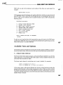
Available Tests and Options
The following sections describe the various tests and the options available. To end any
test or menu option early, hold down the CTRL key and simultaneously type the letter C.
F-
FORMAT DISK SURFACE
The Format Disk Surface option prepares a soft-sectored blank diskette for use with the
TEST diagnostics. Use the Format Disk Surface option with any diskette which has not
previously been formatted for TEST.
The format option begins by instructing you to insert a diskette. For example:
Insert a diskette into unit ?
Press the RETURN key to format the diskette.
At this point, insert a soft-sectored diskette into the drive whose hardware number the
program substituted for? in the sample message given above. When you have inserted
the diskette, press RETURN. Be sure the diskette you insert is either blank or does not
contain any valuable information, since the format option destroys all information on the
diskette which it formats.
U
DOUBLE-DENSITY DISK CONTROLLER
When you have inserted a soft-sectored diskette and pressed RETURN, the system will
print:
Double Density <YES> ?
If you want the formatted diskette to be double-bit density, simply press RETURN; if you
want the formatted diskette to be single-bit density, type NO and press RETURN. The
system will then print:
Double Sided <YES> ?
To create a double-sided diskette (if you have drives that handle double-sided diskettes),
simply press RETURN. If you want to create a single-sided diskette, enter NO and press
RETURN. The system will then print:
80 Tracks <YES> ?
To create a double-track density diskette (80 tracks instead of 40 - again, you must have
the proper drives), press RETURN. To create a single-track density diskette (40 tracks),
enter NO and press RETURN.
When you have responded to the message which asks how many tracks you want on the
formatted disk, TEST will begin to format the tracks on the blank diskette. TEST will
print one asterisk for each track it has formatted. When it has finished formatting the
disk, the system will print:
Disk Formatted. CTRL-C to continue diagnostics.
Otherwise, Insert a diskette into unit ?
Press the RETURN key to format the diskette.
If you want to format more diskettes at this point, insert another blank, soft-sectored
diskette and press RETURN. If you do not want to format more diskettes, type the CTRL
and C keys simultaneously. This will return you to the TEST main menu.
T-
DRIVE SPEED
The drive speed test checks the rotational speed of your drive. During this test, the screen
will display the relative rotational speed of the drive under test. A series of decimal
numbers, which should be close to 1.000, will scroll up the screen, updating as they
scroll. The rotational speed tolerance is one percent. The final value may safely range
anywhere from 0.990 to 1.010. Do not adjust the speed unless it is out of tolerance. Allow
this test to run for about 30 seconds; then type CTRL-C.
If there are any numbers displayed on the terminal which are less than 0.990 or greater
than 1.010, restart the test and carefully adjust the speed adjustment control on the drive
with a small screwdriver until the number is within tolerance. The speed adjustment
control may be extremely sensitive, so if an adjustment is necessary, do not turn it far in
either direction.
You may wish to perform this test periodically, depending on how heavily your drive is
used. The linear servo loop which regulates the drive rotational speed makes this speed
stable. But as the drive bearings wear, the speed may change slightly. Fluctuations
within the tolerance are normal and may be attributed to variations in temperature and
humidity.
14,.13
4- 14 1l....
DOUBLE-DENSITY DISK CONTROLLER
D-
GENERAL DRIVE CHECKOUT
The purpose of the General Drive Checkout is to verify that your system is reading from
and writing to the diskette properly. Each sector on the diskette is written to and read
from a number of times. Various patterns are written on the diskette to allow testing of
the head seek mechanism and the read/write head itself. The test is repeated three times.
Do not be alarmed if this test seems to take an abnormally long time to finish. It is a very
thorough test, and requires from 45 minutes to an hour and a half to complete. The
duration of the test will depend on the type of media you use for the test. Run this test
again only if you encounter problems.
While each pass is being executed, the program will print the letters "ABCDEFG," one
after the other, at intervals of a few minutes. These letters indicate the various phases of
the test and give you an idea of how far it has progressed.
TEST will print an "END OF PASS" message at the end of each pass. There are two
possibilities. If everything proceeds normally, the output for the pass will read:
ABCDEFG END OF PASS n
However, if the test discovers any problems on the current pass, the output will include
the number of "hard" (h) and "soft" (s) errors, as follows:
ABCDE hhh/sss FG END OF PASS n
In this example, test E has errors. The tests corresponding to each letter are:
A = Write all zeroes
B = Read all zeroes
C = Write all ones
D = Read all ones
E = Write identification pattern
F = Read identification pattern
G = Random read/write test
The number of "hard" and "soft" errors is indicated by the numbers "hhh"· and "sss,"
respectively. Let the test run through all three passes, even if it discovers errors.
Soft errors usually indicate that the disk drive temporarily had difficulty reading from or
writing to the diskette. The difficulty may occur because of dust, noise, static electricity,
etc. Soft errors are nothing to be concerned about; you may correct them by simply
repeating the failed process.
If after performing ten retries (in an attempt to correct a soft error) the program still
cannot perform the read or write operation, TEST reclassifies the soft error as a hard
error. Hard errors are.caused by malfunctions in the electronic or electro-mechanical
hardware and/or defective diskettes.
u
DOUBLE-DENSITY DISK CONTROLLER
4-15
_ _ _ _ _ _ _ _ _ _1
.
If you have hard errors, the best approach is to exit this program (type E at the option
menu), format another blank diskette, and repeat the entire TEST procedure. If this
approach is successful, it is probably because the first diskette had one or more bad
sectors, possibly caused by dust. If replacing the diskette corrects the hard errors,
continue through the other TEST options and then use "Switch" to restart TEST. Then
insert the bad diskette and perform "Media Check" in order to identify bad sectors. If the
diskette contains bad sectors, put it aside. Do not use a defective diskette to store data or
programs.
Hard errors on the inside (high numbered) tracks will usually result if you use double-bit
density, double-sided, 80-track operation with diskettes not certified for such use.
If you are getting both hard and soft errors, and "Media Check" finds nothing wrong with
the "bad" disk, you may have hardware problems.
If changing the diskette does not correct the problem, or if you do suspect that you have
hardware problems, refer to the "In Case of Difficulty" section, Page 5-5.
M - MEDIA CHECK
The Media Check will examine the diskette under test for defects in the magnetic oxide
recording medium. If you had any hard or soft errors during the General Drive Checkout,
defects in the diskette medium could be the cause. If the Media Check finds any bad
sectors, the bad sector numbers will be listed at the end ofthe test. Run this test on all new
diskettes to confirm the quality of the medium.
The Media Check will take anywhere from 20 to 45 minutes. At the end of the test, the
following message will be printed:
nnnn
BAD SECTORS LOCATED
The number "nnnn", which can range from 0000 to 2879, tells how many of the sectors
on the diskette under test are defective. The numbers of any bad sectors will also be
listed. Record the numbers for future reference. If the Media Check discovers a bad
sector, put the diskette which contains the bad sector aside. Do not use it to store data or
programs. However, disks which have errors in double-density or double-sided use may
still be suitable for single-density or single-sided use.
S-SEEK TIME
This test will vary the track seek time of your drive in order to determine its highest
reliable speed. The drive assemblies are guaranteed to perform reliably at a seek time of
30 milliseconds per track.
The maximum seek speed may change as the drive unit becomes "broken in." If frequent
read errors occur with one of your drives, you should re-run TEST to check for possible
changes in the drive speed.
4- 16 1
DOUBLE-DENSITY DISK CONTROLl.ER
The first speed to be tested is 30 milliseconds per track. The program will attempt faster
step rates of 20, 12, and 6 milliseconds until it has determined your drive's fastest
reliable seek time. As it tests, the program will print what speed it is attempting. For each
successful pass, TEST will print the message "OK!" to indicate that the drive performs
reliably at that speed.
When the seek time test is complete, the message "Drive performs reliably at nn milliseconds per track" will be printed, where "nn" is the optimum seek time of your drive.
Record this number for future reference.
Note that if TEST attempts a pass at 6 milliseconds per track, it may not print the "Drive
performs reliably... " message, but instead may simply stop execution. If the test attempts
a speed of 6 milliseconds per track but fails to print the "Drive performs reliably... "
message, then the fastest reliable seek time is 12 milliseconds per track. If the test stops
executing without printing any message, type CfRL-C before you proceed to the next
test.
You will probably want to perform this test on your other drives in order to determine the
seek speed for all drives in the system. To do this, use the "Switch" TEST menu option to
change the drive to be tested; then run the seek time test again. Set your operating system
seek speed to that of the slowest drive in your system unless it has the ability to use
different speeds for different drives.
A-ALIGN
NOTE: This procedure is for authorized service personnel only. Unauthorized use may
void your drive warranty.
The Align menu option is used to align the disk drive read/write head. To use this option
you will need an alignment diskette and a dual-trace oscilloscope with algebraic add.
This option causes the disk drive read/write head to select a track on the disk which you
specify. The drive will continue to select the track while you adjust the alignment. You
can then respecify track numbers, continuing this procedure until the tracks on the
alignment diskette produce the desired displays on the oscilloscope. Be sure to read the
disk drive manufacturer's instructions and the alignment disk manufacturer's instructions before using this program.
To use the Align option, enter A and press RETURN when the TEST menu is displayed.
The program will print:
Radial head alignment:
WARNING
Check your manual before proceeding
Insert the ALIGNMENT diskette in drive?
Hit return when ready?
The program will have substituted the hardware number of the drive you have been
testing for the ? in the sample message given above.
Ii
.1
~
DOUBLE-DENSITY DISK CONTROLLER
To begin the alignment procedure, insert the alignment diskette into the drive whose
hardware configuration number appears in the message and press RETURN. The program will print:
Enter track number <0>
At this point, enter the first track number (as directed by the manual provided with the
alignment disk) and press RETURN. The system will then print,
Enter side number <0>
Enter the side number (as per the directions provided with the alignment disk and/or
disk drives) and press RETURN. The system will print:
CTRL-C
CTRL-C
request another track
return to menu
This message instructs you to type CTRL-C once to change the track number which you
entered above, or type CTRL-C twice in succession to return to the TEST menu.
You will probably need to change the track number at least twice, but this will vary, and
you should follow the alignment disk and disk drive manufacturer's instructions, To
change the current track number, type CTRL-C once. The program will print:
Enter track number <0>
Now enter the new track number and press RETURN. The system will again print:
CTRL-C
CTRL-C
request another track
return to menu
When you have selected all tracks designated in the manufacturer's instructions, and
achieved the desired oscilloscope displays for all designated tracks, type CTRL-C twice
in succession to return to the TEST menu.
V-SWITCH
This procedure will restart TEST, thereby enabling you to select another drive unit to be
tested, or to insert a new diskette. After you have typed U and pressed RETURN, TEST
will restart itself. When you are asked which drive you want to test, enter the hardware
number of the drive you want to test. You can change the diskette when you are asked to
insert the diskette you wish to use for this test. If you are inserting a new diskette, be sure
to use TEST menu option F to format the diskette before you perform tests.
Note that using "Switch" will enable you to alternate among your drives for as long as
you wish to test them.
E-EXIT
To exit TEST, type E and press RETURN. This will return you to the diagnostic program's
main menu.
.....14-'17
4-181""""-
DOUBLE-DENSITY DISK CONTROLLER
u
u
----l15..1
DOUBLE-DENSITY DISK CONTROLLER
Service
RECALIBRATION
You will need the following equipment to calibrate your Disk Controller Board:
•
A Digital Voltmeter (DVM) with 3-1/2 digit readout.
•
A calibrated oscilloscope with sweep speeds of 100 ns/cm and 200 ns/cm, and
an operating scale of 5 V peak-to-peak.
•
A Frequency Counter capable of measuring 2.00 MHz. (Optional, but
preferred).
•
HDOS 2.0 modified with INIT or CP/M 2.2.03 with FORMAT software.
If you cannot obtain the proper results in the following steps, refer to the "In Case of
Difficulty" section of this manual and correct any difficulties before proceeding.
Refer to Figure 5-1 (Page 5-3) when you perform the "Recalibration."
5-2 11...--
DOUBLE-DENSITY DISK CONTROLLER
VCO BIAS ADJUSTMENT
Warm up the Computer for a minimum of 15 minutes with the lid closed.
Connect your DVM to test point 1 on the H-/Z-89-37 board; connect the negative lead to
ground and the positive lead to test point 1. The reading should be 1.38 to 1.42 V (this is
the VCO bias voltage). If you do not obtain the proper voltage, adjust control RI0.
Disconnect the DVM.
VCO CENTER FREQUENCY ADJUSTMENT
(WITH FREQUENCY COUNTER)
This is the preferred method of adjusting the VCO's center frequency.
Connect the frequency counter to test point 2 on the board. Set the counter to the 100 ms
time base. The counter should read from 1975 to 2025 kHz. If it does not, adjust control
R17.
Disconnect the counter.
u
DOUBLE-DENSITY DISK CONTROLLER
Figure 5-1
Z-89-37. Part number HE 181-3614
_
15..3
5-4 1
DOUBLE-DENSITY DISK CONTROLLER
VCO CENTER FREQUENCY ADJUSTMENT
(WITH OSCILLOSCOPE)
Connect the oscilloscope's input lead to test point 2.
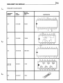
Set the oscilloscope's sweep to 500 ns/cm. The period of the square wave displayed on
the screen should be 493 to 506 ns. If it is not, adjust R17. See Figure 5-2.
500n5
2V
. .. .. .. ... . ...
~ II-
.
~
...
.
~
... ...
.....
~
.
~
Figure 5-2
Disconnect the oscilloscope.
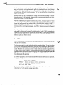
PRECOMPOSITION ADJUSTMENT
Connect the oscilloscope to test point 3.
Set the oscilloscope's sweep to 100 ns/cm.
Using your system's software (INIT in HDOS and FORMAT in CP/M), write on the disk in
double-density mode. The period of the pulse displayed on the screen should be 300 to
350 ns. If it is not, adjust control R20. See Figure 5-3.
2V
-
lOOnS
(
T
Figure 5-3
Disconnect the oscilloscope.
This completes the calibration of your disk controller board.
u
DOUBLE-DENSITY DISK CONTROLLER __ _ _ _ _ _ _ _ _ _ _ _ _ _ _---JI. fi-5
IN CASE OF DIFFICULTY
If your system does not operate properly, make the following checks.
PROBLEM
POSSIBLE CAUSE
Drive access light does not turn on when
disk is booted.
1.
2.
3.
4.
5.
Check for proper connections of floppy cable
inside Computer.
Check for proper connections of rear panel extension
cable inside Computer.
Be sure Z-37 or Z-87 is turned on.
Check positions of J1 and J2 on Z-89-37 circuit board.
Check U550 for correct part and installation.
Drive access light turns on but drive makes
an unusual clicking sound.
1.
Check positions of J4 through J9 on Z-89-37
circuit board.
All disk access lights turn on and remain on.
1.
A cable is connected with marked edge
on the wrong side.
Two drives turn on when a boot operation is
selected.
1.
Two drives have their disk selection jumpers
programmed the same.
Computer only beeps once when turned on.
1.
2.
3.
4.
OFF LINE key in down position. Should be up.
U550, U516, or U518 installed incorrectly.
3" jumper wire installed incorrectly.
16-eonductor cable with plugs installed incorrectly.
Computer will not accept boot command, returns
to H: prompt, or starts to boot but does not
return to H: prompt without reset.
1.
Be sure disk is installed in selected drive
before boot command is given.
If H-88-1 disk I/O is not installed, check for proper
installation of the 4700 n resistor with connectors.
2.
5-6 1
DOUBLE-DENSITY DISK CONTROLLER
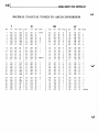
DECIMAL TO OCTAL TO HEX TO ASCII CONVERSION
I
II
DEC
OCT
HEX
ASCII
0
1
2
3
4
5
6
7
000
001
002
003
004
005
006
007
00
01
02
03
04
05
06
07
8
9
10
11
12
13
14
15
010
011
012
013
014
015
016
017
16
17
18
19
20
21
22
23
24
25
26
27
28
29
30
31
III
IV
DEC
OCT
HEX
ASCII
DEC
OCT
HEX
NUL
SOH
STX
ETX
EaT
ENQ
ACK
BEL
32
33
34
35
36
37
38
39
040
041
042
043
044
045
046
047
20
21
22
23
24
25
26
27
SPACE
64
65
66
67
68
69
70
71
100
101
102
103
104
105
106
107
40
41
42
43
44
45
46
47
@
08
09
OA
DB
DC
00
DE
OF'
BS
HT
LF'
VT
F'F'
CR
SO
SI
40
41
42
43
44
45
46
47
050
051
052
053
054
055
056
057
28
29
2A
2B
2C
20
2E
2F'
110
111
112
113
114
115
116
117
48
49
4A
4B
4C
40
4E
4F'
H
I
/
72
73
74
75
76
77
78
79
020
021
022
023
024
025
026
027
10
11
12
13
14
15
16
17
OLE
DCl
DC2
DC3
DC4
NAK
SYN
ETB
48
49
50
51
52
53
54
55
060
061
062
063
064
065
066
067
30
31
32
33
34
35
36
37
0
1
2
3
4
5
6
7
80
81
82
83
84
85
86
87
120
121
122
123
124
125
126
127
50
51
52
53
54
55
56
57
P
Q
R
S
T
U
V
030
031
032
033
034
035
036
037
18
19
lA
lB
lC
10
lE
IF'
CAN
EM
SUB
ESC
F'S
GS
RS
US
56
57
58
59
60
61
62
63
070
071
072
073
074
075
076
077
38
39
3A
3B
3C
3D
3E
3F'
8
9
88
89
90
91
92
93
94
95
130
131
132
133
134
135
136
137
58
59
5A
5B
5C
50
5E
5F'
X
Y
Z
#
$
%
&
*
+
PERIOD
<
>
?
ASCII
A
B
C
0
E
F'
G
J
K
L
M
N
0
W
[
\
]
6,
DEC
OCT
HEX
96
97
98
99
100
101
102
103
140
141
142
143
144
145
146
147
60
61
62
63
64
65
66
67
104
105
106
107
108
109
110
111
150
151
152
153
154
155
156
157
68
69
6A
6B
6C
60
6E
6F'
112
113
114
115
116
117
118
119
160
161
162
163
164
165
166
167
70
71
72
73
74
75
76
77
P
120
121
122
123
124
125
126
127
170
171
172
173
174
175
176
177
78
79
7A
7B
7C
70
7E
7F'
x
y
ASCII
a
b
c
d
e
f
g
h
i
j
k
1
m
n
0
q
r
s
t
u
v
w
z
{
I
}
DELETE
U
16.,1
DOUBLE-DENSITY DISK CONTROLLER
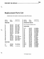
Replacement Parts List
(Double-density disk controller circuit board part number HE 181-3614.)
CIRCUIT
Compo No.
PART
DESCRIPTION
NUMBER
(..;
HE 6-102-12
HE 6-103-12
HE 6-103-12
HE 6-102-12
HE 6-102-12
HE 6-104-12
HE 6-103-12
HE 6-102-12
HE 6-103-12
HE 10-1180
HE 6-473-12
HE 6-473-12
HE 6-680-12
Not Used
Not Used
HE 6-2002-12
HE 10-1154
HE 6-1002-12
HE 6-222-12
HE 10-1138
HE 6-124-12
HE 6-332-12
1000 il, 1/4-watt
10 kil, 1/4-watt
10 kil, 1/4-watt
1000 il, 1/4-watt
1000 il, 1/4-watt
100 kil, 1/4-watt
10 kil, 1/4-watt
1000 il, 1/4-watt
10 kil, 1/4-watt
100 kil control
47 kil, 1/4-watt
47 kil, 1/4-watt
68 il, 1/4-watt
20 kil, 1/4-watt
10 kil, 1/2-watt control
10 kil, 1/4-watt
2200 il, 1/4-watt
10 kil, 314-watt control
120 kil, 1/4-watt
3300 il, 1/4-watt
INDUCTORS
L1-L7
L8
L9
L10-L37
PART
DESCRIPTION
NUMBER
INTEGRATED CIRCUITS
RESISTORS
R1
R2
R3
R4
R5
R6
R7
R8
R9
R10
R11
R12
R13
R14
R15
R16
R17
R18
R19
R20
R21
R22
CIRCUIT
Comp No.
HE 235-192
HE 235-230
Not Used
HE 235-230
35 IJoH, RF Choke
7 IJoH, Ferrite Core
7 IJoH, Ferrite Core
See the "Semiconductor Identification Charts."
CAPACITORS
C1-C16
C17
C18
C19
C20
C21
C22
C23
C24
C25
C26
C27
C28
C29
C30
C31
C32
C33
C34
C35
C36-C63
C64
C65-C66
C67
C68
C69
HE 21-769
HE 25-911
HE 21-769
HE 25-911
HE 21-769
HE 21-141
HE 21-769
HE 21-769
HE 21-769
HE 21-769
HE 21-769
HE 20-96
HE 21-769
HE 27-217
HE 21-192
HE 25-195
HE 21-744
HE 21-192
HE 21-769
HE 25-197
HE 21-773
HE 25-883
HE 25-841
HE 21-769
HE 25-841
HE 21-769
*OuPont Registered Trademark
.01 IJoF ceramic
22 IJoF electrolytic
.01 IJoF ceramic
22 IJoF electrolytic
.01 IJoF ceramic
.0033 IJoF ceramic
.01 IJoF ceramic
.01 IJoF ceramic
.01 IJoF ceramic
.01 IJoF ceramic
.01 IJoF ceramic
36 pF mica
.01 IJoF ceramic
.68 IJoF Mylar*
.1 IJoF ceramic
2.2 IJoF tantalum
82 pF ceramic
.1 IJoF ceramic
.01 IJoF ceramic
1 IJoF tantalum
470 pF ceramic
47 IJoF electrolytic
4.7 IJoF tantalum
.01 IJoF ceramic
4.7 IJoF tantalum
.011JoF ceramic
6-2 11..-
DOUBLE-DENSITY DISK CONTROLLER
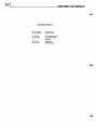
MISCELLANEOUS
PART NUMBER
DESCRIPTION
HE 181-3614
HE 134-1158
89-37 controller board
16 conductor cable
with plug
HE 134-1074
HE 134-1163
Floppy cable
Extension cable
u
~l7 ··1
DOUBLE-DENSITY DISK CONTROLLER
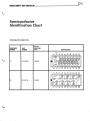
Semiconductor
Identification Chart
INTEGRATED CIRCUITS
COMPONENT
NUMBER
PART
NUMBER
MAYBE
REPLACED
WITH
U1
HE 443-885
74LS245
U2
HE 443-754
74LS240
IDENTIFICATION
7-21
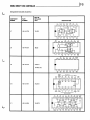
DOUBLE-DENSITY DISK CONTROLLER
Integrated Circuits (Cont'd.)
COMPONENT
NUMBER
PART
NUMBER
u
MAYBE
REPLACED
WITH
IDENTIFICATION
INPUTS
OUTPUT
AD
Vee
U3
HE 443-912
74LS148
-..INPUTS
U4
HE 444-81
*
U5
HE 443-745
74LS03P
Vee
WE
RE
OUTPUTS
ii"OTN
A'
IN
11
U6
HE 444-82
*
7
AD
*Only available from Heath Co.
AI
A'J
Rii"
WR
Be
R/wEN
IN
RTSIT
GND
u
17--3
DOUBLE-DENSITY DISK CONTROLLER
Integrated Circuits (Cont'd.)
COMPONENT
NUMBER
PART
NUMBER
MAYBE
REPLACED
WITH
U7
HE 443-730
74LS74
U8
HE 443·727
96L02
U9
HE 150-107
LOCO II
IDENTIFICATION
16 MHz Ose.
RIPPLE
CARRY
OUTPUT
OUTPUTS
15
U10
HE 443-757
74LS161
I
CLEAR
U11
HE 443·805
74LS273
7
CLOCK
C
ENABLE
-----..---- P
DATA INPUTS
7-4 1_ _--------------DOUBLE-DENSITY DISK CONTROLLER
Integrated Circuits (Cont'd.)
COMPONENT
NUMBER
PART
NUMBER
u
MAYBE
REPLACED
WITH
IDENTIFICATION
>
c
~
c:
0
cc
'"
~
>
U12
HE 443·997
>
""~
~
+
z
D
WD1797·02
20
~
>
~
z
'"
INPUTS
INPUTS
OUTPUT
3Y
Vee
9
U13
HE 443·799
74LS157
I
SELECT
3
IB
----IA
INPUTS
Vee
U14
HE 443-90
74123N
U15
HE 443-857
74LS367
4
IY
OUTPUT
5
2A
-----
2B
INPUTS
iO
7
2Y
OUTP:JT
2B
u
DOUBLE-DENSITY DISK CONTROLLER
C,
.....,11
Integrated Circuits (Cont'd)
COMPONENT
NUMBER
PART
NUMBER
MAYBE
REPLACED
WITH
U16
HE 443-998
WD1691
IDENTIFICATION
t::;)
o
'"s:
U17
HE 443-999
74LS624
C'
Vee
PREAMP
ADJ.
OPW
17
U18
HE 443-1000
WD2143-03
U19, U20,
U21, U22
HE 443-73
7416N
U23
HE 442-627
78L05
~
G:P'
'"
IN
I~
7..5
-6IL
7
DOUBLE-DENSITY DISK CONTROLLER
DOUBLE.DENSITY DISK. CONTROLLER
~
•
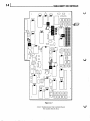
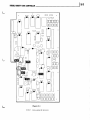
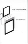
Circuit Board X-Ray View
NOTE: To find the PART NUMBER of a component for the purpose of ordering a
replacement part:
•
A.
Find the circuit component number (Ci0i, Ci04, etc.) on the X-Ray View.
B.
Locate the same number in the "Circuit Component Number" columns of the
"Replacement Parts List."
C.
Adjacent to the circuit component number, you will find the PART NUMBER and
DESCRIPTION which must be supplied when you order a replacement part.
__.;..._18~1
•
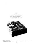
Z-89-37 DOUBLE-DENSITY DISK CONTROLLER BOARD
Part number HE 181-3614. Shown from the component side.
8-21
DOUBLE..DENSITY DISK CONTROLLER
•