1
Sun Storage 7000
Unified Storage System
Service Manual
Part No: 821–1388–10 Rev. A
February 2010
Copyright ©2010 Sun Microsystems, Inc.
4150 Network Circle, Santa Clara, CA 95054 U.S.A.
All rights reserved.
Sun Microsystems, Inc. has intellectual property rights relating to technology embodied in the product that is described in this document. In particular, and without
limitation, these intellectual property rights may include one or more U.S. patents or pending patent applications in the U.S. and in other countries.
U.S. Government Rights – Commercial software. Government users are subject to the Sun Microsystems, Inc. standard license agreement and applicable provisions
of the FAR and its supplements.
This distribution may include materials developed by third parties.
Parts of the product may be derived from Berkeley BSD systems, licensed from the University of California. UNIX is a registered trademark in the U.S. and other
countries, exclusively licensed through X/Open Company, Ltd.
Sun, Sun Microsystems, the Sun logo, the Solaris logo, the Java Coffee Cup logo, docs.sun.com, ZFS, Java, and Solaris are trademarks or registered trademarks of Sun
Microsystems, Inc. or its subsidiaries in the U.S. and other countries. All SPARC trademarks are used under license and are trademarks or registered trademarks of
SPARC International, Inc. in the U.S. and other countries. Products bearing SPARC trademarks are based upon an architecture developed by Sun Microsystems, Inc.
The OPEN LOOK and SunTM Graphical User Interface was developed by Sun Microsystems, Inc. for its users and licensees. Sun acknowledges the pioneering efforts
of Xerox in researching and developing the concept of visual or graphical user interfaces for the computer industry. Sun holds a non-exclusive license from Xerox to
the Xerox Graphical User Interface, which license also covers Sun's licensees who implement OPEN LOOK GUIs and otherwise comply with Sun's written license
agreements.
Products covered by and information contained in this publication are controlled by U.S. Export Control laws and may be subject to the export or import laws in
other countries. Nuclear, missile, chemical or biological weapons or nuclear maritime end uses or end users, whether direct or indirect, are strictly prohibited. Export
or reexport to countries subject to U.S. embargo or to entities identified on U.S. export exclusion lists, including, but not limited to, the denied persons and specially
designated nationals lists is strictly prohibited.
DOCUMENTATION IS PROVIDED “AS IS” AND ALL EXPRESS OR IMPLIED CONDITIONS, REPRESENTATIONS AND WARRANTIES, INCLUDING ANY
IMPLIED WARRANTY OF MERCHANTABILITY, FITNESS FOR A PARTICULAR PURPOSE OR NON-INFRINGEMENT, ARE DISCLAIMED, EXCEPT TO
THE EXTENT THAT SUCH DISCLAIMERS ARE HELD TO BE LEGALLY INVALID.
Copyright ©2010 Sun Microsystems, Inc.
4150 Network Circle, Santa Clara, CA 95054 U.S.A.
Tous droits réservés.
Sun Microsystems, Inc. détient les droits de propriété intellectuelle relatifs à la technologie incorporée dans le produit qui est décrit dans ce document. En particulier,
et ce sans limitation, ces droits de propriété intellectuelle peuvent inclure un ou plusieurs brevets américains ou des applications de brevet en attente aux Etats-Unis
et dans d'autres pays.
Cette distribution peut comprendre des composants développés par des tierces personnes.
Certaines composants de ce produit peuvent être dérivées du logiciel Berkeley BSD, licenciés par l'Université de Californie. UNIX est une marque déposée aux
Etats-Unis et dans d'autres pays; elle est licenciée exclusivement par X/Open Company, Ltd.
Sun, Sun Microsystems, le logo Sun, le logo Solaris, le logo Java Coffee Cup, docs.sun.com, ZFS, Java et Solaris sont des marques de fabrique ou des marques déposées
de Sun Microsystems, Inc., ou ses filiales, aux Etats-Unis et dans d'autres pays. Toutes les marques SPARC sont utilisées sous licence et sont des marques de fabrique
ou des marques déposées de SPARC International, Inc. aux Etats-Unis et dans d'autres pays. Les produits portant les marques SPARC sont basés sur une architecture
développée par Sun Microsystems, Inc.
L'interface d'utilisation graphique OPEN LOOK et Sun a été développée par Sun Microsystems, Inc. pour ses utilisateurs et licenciés. Sun reconnaît les efforts de
pionniers de Xerox pour la recherche et le développement du concept des interfaces d'utilisation visuelle ou graphique pour l'industrie de l'informatique. Sun détient
une licence non exclusive de Xerox sur l'interface d'utilisation graphique Xerox, cette licence couvrant également les licenciés de Sun qui mettent en place l'interface
d'utilisation graphique OPEN LOOK et qui, en outre, se conforment aux licences écrites de Sun.
Les produits qui font l'objet de cette publication et les informations qu'il contient sont régis par la legislation américaine en matière de contrôle des exportations et
peuvent être soumis au droit d'autres pays dans le domaine des exportations et importations. Les utilisations finales, ou utilisateurs finaux, pour des armes nucléaires,
des missiles, des armes chimiques ou biologiques ou pour le nucléaire maritime, directement ou indirectement, sont strictement interdites. Les exportations ou
réexportations vers des pays sous embargo des Etats-Unis, ou vers des entités figurant sur les listes d'exclusion d'exportation américaines, y compris, mais de manière
non exclusive, la liste de personnes qui font objet d'un ordre de ne pas participer, d'une façon directe ou indirecte, aux exportations des produits ou des services qui
sont régis par la legislation américaine en matière de contrôle des exportations et la liste de ressortissants spécifiquement designés, sont rigoureusement interdites.
LA DOCUMENTATION EST FOURNIE "EN L'ETAT" ET TOUTES AUTRES CONDITIONS, DECLARATIONS ET GARANTIES EXPRESSES OU TACITES
SONT FORMELLEMENT EXCLUES, DANS LA MESURE AUTORISEE PAR LA LOI APPLICABLE, Y COMPRIS NOTAMMENT TOUTE GARANTIE
IMPLICITE RELATIVE A LA QUALITE MARCHANDE, A L'APTITUDE A UNE UTILISATION PARTICULIERE OU A L'ABSENCE DE CONTREFACON.
100302@23474
Contents
Preface .....................................................................................................................................................7
1
Introduction .........................................................................................................................................11
Overview ............................................................................................................................................... 11
Introduction ................................................................................................................................. 11
Hardware .............................................................................................................................................. 14
Hardware View ............................................................................................................................. 15
BUI ................................................................................................................................................. 15
CLI ................................................................................................................................................. 21
Tasks .............................................................................................................................................. 23
2
Hardware Maintenance ......................................................................................................................25
Maintenance ........................................................................................................................................ 25
Introduction ................................................................................................................................. 26
7110 ....................................................................................................................................................... 26
Hardware Overview ..................................................................................................................... 26
7210 ....................................................................................................................................................... 37
Hardware Overview ..................................................................................................................... 37
7310 ....................................................................................................................................................... 42
Hardware Overview ..................................................................................................................... 42
7410 ....................................................................................................................................................... 54
Hardware Overview ..................................................................................................................... 54
Details ................................................................................................................................................... 69
Controller Maintenance Procedures ......................................................................................... 69
Prerequisites ................................................................................................................................. 70
Safety Information ....................................................................................................................... 70
Required Tools and Serial Numbers .......................................................................................... 70
3
Contents
Tasks .............................................................................................................................................. 71
Next Steps ...................................................................................................................................... 88
Shelf ....................................................................................................................................................... 89
Disk Shelf Overview ..................................................................................................................... 89
Shelf ....................................................................................................................................................... 97
Disk Shelf Maintenance Procedures .......................................................................................... 97
Prerequisites ................................................................................................................................. 97
Safety Information ....................................................................................................................... 97
Electrostatic Discharge Precautions .......................................................................................... 98
Tasks .............................................................................................................................................. 98
3
System Maintenance .........................................................................................................................105
System ................................................................................................................................................. 105
Introduction ............................................................................................................................... 105
System Disks ............................................................................................................................... 105
Support Bundles ......................................................................................................................... 106
Initial Setup ................................................................................................................................. 107
Factory Reset ............................................................................................................................... 108
Updates ............................................................................................................................................... 108
System Updates .......................................................................................................................... 108
ConfigurationBackup ....................................................................................................................... 121
Configuration Backup ............................................................................................................... 121
Problems ............................................................................................................................................. 126
Problems ..................................................................................................................................... 126
Active problems display ............................................................................................................ 126
Repairing problems ................................................................................................................... 126
Related features .......................................................................................................................... 127
Logs ..................................................................................................................................................... 127
Introduction ............................................................................................................................... 127
BUI ............................................................................................................................................... 129
CLI ............................................................................................................................................... 129
4
Sun Storage 7000 Unified Storage System Service Manual • February 2010
Contents
Glossary .............................................................................................................................................. 131
Index ................................................................................................................................................... 135
5
6
Preface
The Sun Storage 7000 Unified Storage System Service Manual contains hardware overviews and
maintenance procedures for the Sun Storage 7000 series of NAS appliances.
This documentation is also available while using the Browser User Interface, accessible via the
Help button. The appliance documentation may be updated using the System Upgrade
procedure documented in Chapter 1 of this book.
Who Should Use This Book
These notes are for users and system administrators who service and use the Sun Storage 7000
server appliances.
Related Documentation
Refer to the following documentation for installation instructions, hardware overviews, service
procedures and software update notes.
■
■
Installation Guide and Administration Guide (http://wikis.sun.com/display/
fishworks/documentation/)
Release Notes (http://wikis.sun.com/display/fishworks/software+updates)
Third-Party Web Site References
Third-party URLs are referenced in this document and provide additional, related information.
7
Preface
Note – Sun is not responsible for the availability of third-party Web sites mentioned in this
document. Sun does not endorse and is not responsible or liable for any content, advertising,
products, or other materials that are available on or through such sites or resources. Sun will not
be responsible or liable for any actual or alleged damage or loss caused by or in connection with
the use of or reliance on any such content, goods, or services that are available on or through
such sites or resources.
Documentation, Support, and Training
The Sun web site provides information about the following additional resources:
■
■
■
Documentation (http://www.sun.com/documentation/)
Support (http://www.sun.com/support/)
Training (http://www.sun.com/training/)
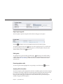
Typographic Conventions
The following table describes the typographic conventions that are used in this book.
TABLE P–1
Typographic Conventions
Typeface
Meaning
Example
AaBbCc123
The names of commands, files, and directories,
and onscreen computer output
Use the help command to show
available actions.
Last login: Mon Oct 13 15:43:05
2008 from kiowa
AaBbCc123
What you type, contrasted with onscreen
computer output
caji console login: root
Password:
aabbcc123
Placeholder: replace with a real name or value
To view an individual property, use
get propertyname.
AaBbCc123
Book titles, new terms, and terms to be
emphasized
Read Chapter 6 in the User's Guide.
A cache is a copy that is stored
locally.
Do not save the file.
Note: Some emphasized items
appear bold online.
8
Sun Storage 7000 Unified Storage System Service Manual • February 2010
Preface
CLI Prompts in Command Examples
The following table shows the default Command Line Interface prompts for the appliance.
TABLE P–2
CLI Prompts
Type
Prompt
Appliance CLI
machine_name:>
9
10
1
C H A P T E R
1
Introduction
Overview
Introduction
The Sun Storage 7000 Unified Storage family of products provide efficient file and block data
services to clients over a network, and a rich set of data services that can be applied to the data
stored on the system.
Platforms
■
■
■
■
■
Sun Storage 7110
Sun Storage 7210
Sun Storage 7310
Sun Storage 7410
Sun Disk Shelf J4400/J4410/J4500
Protocols
The Unified Storage products include support for a variety of industry-standard client
protocols, including:
■
■
■
CIFS
NFS
HTTP and HTTPS
11
Overview
■
■
■
■
■
WebDAV
iSCSI
FC
FTP
SFTP
Key Features
Your Sun Storage system also includes new technologies to deliver the best storage
price/performance and unprecedented observability of your workloads in production,
including:
■
Analytics, a system for dynamically observing the behavior of your system in real-time and
viewing data graphically
■
The ZFS Hybrid Storage Pool, composed of optional Flash-memory devices for acceleration
of reads and writes, low-power, high-capacity disks, and DRAM memory, all managed
transparently as a single data hierarchy
Data Services
To manage the data that you export using these protocols, you can configure your Sun Storage
system using the built-in collection of advanced data services, including:
■
■
■
■
■
■
■
■
■
RAID-Z (RAID-5 and RAID-6), mirrored, and striped disk configurations
Unlimited read-only and read-write snapshots, with snapshot schedules
Data deduplication
Built-in data compression
Remote replication of data for disaster recovery
Active-active clustering for high availability (7310 and 7410)
Thin provisioning of iSCSI LUNs
Virus scanning and quarantine
NDMP backup and restore
Availability
To maximize the availability of your data in production, the Sun Storage products include a
complete end-to-end architecture for data integrity, including redundancies at every level of the
stack. Key features include:
12
■
Predictive Self-Healing and diagnosis of all system hardware failures: CPUs, DRAM, I/O
cards, disks, fans, power supplies
■
ZFS end-to-end data checksums of all data and metadata, protecting data throughout the
stack
■
RAID-6 (DP) and optional RAID-6 across disk shelves
■
Active-active clustering for high availability (7310 and 7410)
Sun Storage 7000 Unified Storage System Service Manual • February 2010
Overview
■
Link aggregations and IP multipathing for network failure protection
■
I/O Multipathing between the controller and disk shelves
■
Integrated software restart of all system software services
■
Phone-Home of telemetry for all software and hardware issues
■
Lights-out Management of each system for remote power control and console access
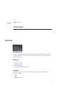
Browser User Interface (BUI)
The browser user interface
The BUI is the graphical tool for administration of the appliance. The BUI provides an intuitive
environment for administration tasks, visualizing concepts, and analyzing performance data.
The management software is designed to be fully featured and functional on the following
supported web browsers: Firefox 2.x and 3.x, Internet Explorer 7 and 8, Safari 3.1 or later, and
WebKit 525.13 or later.
Direct your browser to the system using either the IP address or host name you assigned to the
NET0 port as follows: https://ipaddress:215 or https://hostname:215. The login screen appears.
Chapter 1 • Introduction
13
Hardware
Command Line Interface (CLI)
The CLI is designed to mirror the capabilities of the BUI, while also providing a powerful
scripting environment for performing repetitive tasks. The following sections describe details of
the CLI. When navigating through the CLI, there are two principles to be aware of:
■
Tab completion is used extensively - if you are not sure what to type in any given context,
pressing the Tab key will provide you with possible options. Throughout the
documentation, pressing Tab is presented as the word "tab" in bold italics.
■
Help is always available - the help command provides context-specific help. Help on a
particular topic is available by specifying the topic as an argument to help, for example help
commands. Available topics are displayed by tab-completing the help command, or by typing
help topics.
You can combine these two principles, as follows:
dory:> help tab
builtins
commands
general
help
properties script
Hardware
14
Sun Storage 7000 Unified Storage System Service Manual • February 2010
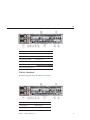
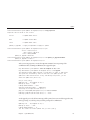
Hardware
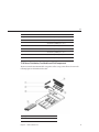
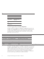
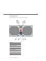
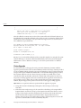
Locating a disk
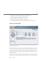
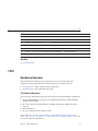
Hardware View
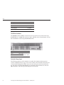
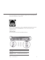
The Maintenance > Hardware screen (also known as the "hardware view") provides component
status of the appliance and attached disk shelves. This information is available from both the
BUI and the CLI.
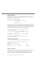
BUI
The BUI hardware view provides interactive illustrations that enable you to browse through the
appliance and attached disk shelf components. The screenshot at the top of this page shows a
disk highlighted in a Sun Storage 7110, showing both its physical location and details.
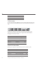
The buttons in the hardware view are:
Chapter 1 • Introduction
15
Hardware
icon
description
Show a more detailed view of this component
Leave this detailed view
Click for more details
Hardware component is ok (green)
Hardware component is not present (grey)
Hardware component is faulted (amber)
Toggle blinking of the locator LED for this component
Reboot the appliance
Power off the appliance
Offline disk
Port active
Port inactive
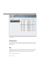
System Overview
The main hardware page lists the system chassis, a summary of its contents, and any attached
disk shelves (on supported systems). This provides an overview of the hardware present on the
system, as well as controls to reset or power off the system.
System Chassis
The primary system chassis is shown on the top half of the view. At the top left, click the
to
get more detail about the chassis. The indicator notes if there are any faulted components
within the chassis, and the name of the chassis. The chassis name is initially set to be equal to the
appliance name during installation. To change the chassis name, use the entry field on the
Configuration > Services > System Identity screen.
At the top right of the system chassis is the
control to light the locate LED,
reboot the
appliance, and
power off the chassis. Note that in a 7310 or 7410 configuration, the system
chassis does not control the disk shelf power. The reboot and poweroff operations are identical
to those provided at the top left of the global sub-navigation bar.
16
Sun Storage 7000 Unified Storage System Service Manual • February 2010
Hardware
A thumbnail of the system chassis is presented at left. Clicking on the thumbnail or the "Show
Details" link takes you to a detailed view of the chassis, and is identical to clicking on the right
pointing arrow at the top left of the view.
The following information is presented in a summary view:
Property
Description
Manufacturer
Manufacturer of the system
Model
System model name
Serial
System chassis hardware serial number
Processors
Count and description of processors in the system
Memory
Total memory in the system
System
Size and number of system disks used for the system image
Data
Size and number of data disks in the system chassis. This is only valid for standalone
systems. If there are no data disks present, "-" will be displayed.
Cache
Size and number of cache disks in the system chassis. This is only valid for expandable
systems that support additional disk shelves. If there are no cache disks present, "-"
will be displayed.
Log
Size and number of log disks in the system chassis. This is only valid for standalone
systems. If there are no log devices present, "-" will be displayed.
Total
Total size and count of all disks in the system.
Disk Shelves
A list of disk shelves, if supported, is displayed at the bottom of the view. The thumbnail to the
left represents the front of the currently selected disk shelf. Clicking on the right pointing arrow
or double-clicking on a row within the list will provide complete details about the disk shelf.
The state indicator will be orange if the chassis contains any faulted components. The following
fields are displayed in the list:
Property
Description
Name
Name of the disk shelf, used in faults and alerts. This is initially set to the serial
number of the disk shelf, but can be changed by clicking on the name within the list.
Manufacturer
Disk Shelf Manufacturer
Model
Disk Shelf Model
Data
Total size of all data disks within the disk shelf.
Chapter 1 • Introduction
17
Hardware
Property
Description
Cache
Total size of all cache disks within the disk shelf. There are currently no supported
disk shelves with cache devices, but this may not always be the case. If there are no
cache disks within the disk shelf, then "-" is displayed.
Log
Total size of all log disks within the disk shelf. If there are no log disks within the disk
shelf, then "-" is displayed.
Paths
Total number of I/O paths to the disk shelf. The only supported configurations are
those with multiple paths to all disks, so this should read "2" under normal
operating circumstances. Clicking the
icon will bring up a dialog with
information about each path. This includes which HBAs are connected to the disk
shelf, and the state of any paths. If the disks within the disk shelf are not currently
configured as part of a storage pool, then complete path information will not be
available, though it should still display two paths to the chassis.
Locate
Toggle the locate LED for this disk shelf. If the LED is currently on, then this
indicator will be flashing.
Chassis Detail
To view the chassis details, click on the
icon (or one of the alternative forms described
above). This view includes some of the same controls in the upper left (state, name, locate, reset,
poweroff), as well as listings of all the components in the chassis.
At the left is a set of images describing the chassis. If there are multiple views, then you can
switch between them by clicking on the name of the view above the image. The following views
are supported:
■
■
■
■
Front
Back
Top
Mezzanine (Sun Storage 7410 only)
For each view, faulted components will be highlighted in red. In addition, the currently selected
component will be highlighted in the image. Clicking on a component within the image will
select the corresponding component in the list to the right.
A tab is present for each component type in the following list. Each component type has a state
icon which will be orange if there is a faulted component of the given type.
■
■
■
■
■
■
■
18
Disks
Slots
CPU (System chassis only)
Memory (System chassis only)
Fans
PSUs (Power Supplies)
SP (Service Processor) (System chassis only)
Sun Storage 7000 Unified Storage System Service Manual • February 2010
Hardware
Clicking on a component type will display a list of all physical locations within the chassis where
components may be present. Clicking on a component within the list will highlight it within the
appropriate chassis image. Clicking on the
icon while over a row or double-clicking a row
will bring up a dialog with detailed information about the component. The information
displayed in the list depends on the component type, but is a subset of the information available
in the component detail. Disks and service processors support additional operations described
below. Each component can report any or all of the following properties:
Property
Description
Label
Human-readable identifier for this component within the chassis. This is typically,
but not necessarily, equivalent to the label printed on the physical chassis.
FMRI
Fault managed resource identifier (FMRI) for the component. This is an internal
identifier used to identify the component within faults and is intended for service
personnel.
Active Problems
For a faulted component, links to active problems affecting the component.
Manufacturer
Component manufacturer.
Model
Component model.
Build
Manufacturing build identifier. This is used to identify a particular location or batch
where the component was manufactured.
Part
Component part number. This is the core factory part number. The actual orderable
part number may differ depending on whether the component is for replacement or
expansion, and whether it's part of a larger assembly. Your service provider should be
able to refer you to the appropriate orderable part. For components without part
numbers, the model number should be used instead.
Serial
Component serial number.
Revision
Firmware or hardware revision of the component.
Size
DIMM or disk size, in bytes.
Type
Disk type. Can be one of 'system', 'data', 'log', 'cache', or 'spare'. When a spare is active,
it will be displayed as 'spare '.
Speed
CPU speed, in hertz.
Cores
Number of CPU cores.
GUID
Hardware global unique identifier.
Disks
Disks support the additional options:
Chapter 1 • Introduction
19
Hardware
Action
Description
Locate
Toggle the locate indicator for the disk. If the LED is currently turned on, this icon
will be blinking.
Offline
Online
Offline the disk. This option is only available for disks that are part of a configured
storage pool (including the system pool). Offlining a disk prevents the system from
reading or writing to it. Faulted devices are already avoided, so this option should
only be required if a disk is exhibiting performance problems that do not result in
pathological failure. It is not possible to offline a disk that would prevent access to data
(i.e. offlining both halves of a mirror). If the device is an active hot spare, this will also
give the option of detaching the hot spare completely. Once a hot spare is detached, it
cannot be activated except through another fault or hotplug event.
Online the disk. Reverses the above operation.
Infiniband Host Controller Adapters
Infiniband Host Controller Adapters (HCA) report additional properties for the list of available
ports:
Action
Description
State
When "active", the active port icon
is displayed. Other valid port states ("down",
"init", and "arm") are denoted by the inactive port icon
icon will display the current port state in the tip pop-up.
GUID
The hardware assigned port GUID.
Speed
The current port speed enabled: SDR, DDR or QDR
. Mousing over the port
Service Processor
The service processor behaves differently from other component nodes. Instead of providing a
list of components, it presents a set of network properties that can be configured from the
storage appliance. The following properties control the behavior of the service processor
network management port.
20
Property
Description
MAC Address
Hardware MAC address. This is read-only
IP Address
Source
One of 'DHCP' or 'Static'. Controls whether DHCP should be used on the interface.
IP Address
IPv4 Address, when using static IP configuration. IPv6 is not supported.
Subnet
Dotted decimal subnet, when using static IP configuration.
Sun Storage 7000 Unified Storage System Service Manual • February 2010
Hardware
Property
Description
Default Gateway
IPv4 default gateway address.
Changing multiple values in conflicting ways (such as changing static IP assignments while in
DHCP mode) has undefined behavior.
CLI
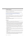
Hardware status details are available in the CLI under the maintenance hardware section. Use
show to list the status of all components. The list command will list available chassis, which
can be selected and then viewed using show.
tarpon:> maintenance hardware show
Chassis:
NAME
STATE
MANUFACTURER
chassis-000 0839QCJ01A
ok
Sun Microsystems, Inc. Sun Storage 7410
cpu-000
cpu-001
cpu-002
cpu-003
disk-000
disk-001
disk-002
disk-003
disk-004
disk-005
disk-006
disk-007
fan-000
fan-001
fan-002
fan-003
fan-004
fan-005
fan-006
fan-007
memory-000
memory-001
...
ok
ok
ok
ok
ok
ok
absent
absent
absent
absent
ok
ok
ok
ok
ok
ok
ok
ok
ok
ok
ok
ok
AMD
AMD
AMD
AMD
STEC
STEC
HITACHI
HITACHI
unknown
Sun Microsystems,
Sun Microsystems,
Sun Microsystems,
unknown
Sun Microsystems,
Sun Microsystems,
Sun Microsystems,
HYNIX
HYNIX
CPU 0
CPU 1
CPU 2
CPU 3
HDD 0
HDD 1
HDD 2
HDD 3
HDD 4
HDD 5
HDD 6
HDD 7
FT 0
FT 0 FM 0
FT 0 FM 1
FT 0 FM 2
FT 1
FT 1 FM 0
FT 1 FM 1
FT 1 FM 2
DIMM 0/0
DIMM 0/1
MODEL
Inc.
Inc.
Inc.
Inc.
Inc.
Inc.
Quad-Core AMD Op
Quad-Core AMD Op
Quad-Core AMD Op
Quad-Core AMD Op
MACH8 IOPS
MACH8 IOPS
HTE5450SASUN500G
HTE5450SASUN500G
ASY,FAN,BOARD,H2
541-2068
541-2068
541-2068
ASY,FAN,BOARD,H2
541-2068
541-2068
541-2068
4096MB DDR-II 66
4096MB DDR-II 66
A 5th column for serial number ("SERIAL") has been truncated in the above example, as has the
length of this list.
Chapter 1 • Introduction
21
Hardware
Component Properties
If a particular component is selected, detailed information about its properties are reported.
The following properties are supported, with the corresponding BUI property name. For a
description of a particular property, see the description above.
CLI Property
BUI Property
build
Build
cores
Cores
device
N/A
faulted
(status indicator)
label
Label
locate (writable)
(status indicator)
manufacturer
Manufacturer
model
Model
offline
(writeable)
(status indicator)
part
Part
present
(status indicator)
revision
Revision
serial
Serial
size
Size
speed
Speed
type
(combined with
use)
use
Type
When viewing a disk that is active as a hot spare, the detach command is also available.
Viewing CPU details
For example, the following shows details for component "CPU 0":
tarpon:maintenance hardware> select chassis-000
tarpon:maintenance chassis-000> select cpu
tarpon:maintenance chassis-000 cpu> select cpu-000
22
Sun Storage 7000 Unified Storage System Service Manual • February 2010
Hardware
tarpon:maintenance chassis-000
Properties:
label
present
faulted
manufacturer
model
part
revision
cores
speed
cpu-000> show
=
=
=
=
=
=
=
=
=
CPU 0
true
false
AMD
Quad-Core AMD Opteron(tm) Processor 8356
1002
03
4
2.14G
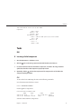
Tasks
BUI
▼ Locating a failed component
1
Go to the Maintenance > Hardware screen.
2
Click the
3
Locate the fault icon in the lists of hardware components, and click it. The image should be
updated to show where that component is physically located.
4
Optionally, click the
icon for that component, if the component has it. The LED on the
component will begin to flash.
icon on the Storage System or Disk Shelf which has the fault icon.
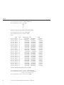
CLI
To turn on the locate LED using the CLI, run the following commands.
Go to the maintenance hardware context:
knife:> maintenance hardware
List the appliance components:
knife:maintenance hardware> list
NAME
STATE
chassis-000 knife
ok
chassis-001 000000000C faulted
MODEL
SERIAL
Sun Storage 7410 unknown
J4400
000000000C
Select the chassis and list its components:
Chapter 1 • Introduction
23
Hardware
knife:maintenance hardware> select chassis-001
knife:maintenance chassis-001> list
disk
fan
psu
slot
Select the component type and show all available disks:
knife:maintenance chassis-001> select disk
knife:maintenance chassis-001 disk> show
Disks:
disk-000
disk-001
disk-002
disk-003
disk-004
disk-005
disk-006
disk-007
disk-008
disk-009
disk-010
disk-011
disk-012
disk-013
disk-014
disk-015
disk-016
disk-017
disk-018
disk-019
disk-020
disk-021
disk-022
disk-023
LABEL
HDD 0
HDD 1
HDD 2
HDD 3
HDD 4
HDD 5
HDD 6
HDD 7
HDD 8
HDD 9
HDD 10
HDD 11
HDD 12
HDD 13
HDD 14
HDD 15
HDD 16
HDD 17
HDD 18
HDD 19
HDD 20
HDD 21
HDD 22
HDD 23
STATE
MANUFACTURER MODEL
ok
ST3500630NS ST3500630NS
faulted ST3500630NS ST3500630NS
ok
ST3500630NS ST3500630NS
ok
ST3500630NS ST3500630NS
ok
ST3500630NS ST3500630NS
ok
ST3500630NS ST3500630NS
ok
ST3500630NS ST3500630NS
ok
ST3500630NS ST3500630NS
ok
ST3500630NS ST3500630NS
ok
ST3500630NS ST3500630NS
ok
ST3500630NS ST3500630NS
ok
ST3500630NS ST3500630NS
ok
ST3500630NS ST3500630NS
ok
ST3500630NS ST3500630NS
ok
ST3500630NS ST3500630NS
ok
ST3500630NS ST3500630NS
ok
ST3500630NS ST3500630NS
ok
ST3500630NS ST3500630NS
ok
ST3500630NS ST3500630NS
ok
ST3500630NS ST3500630NS
ok
ST3500630NS ST3500630NS
ok
ST3500630NS ST3500630NS
ok
ST3500630NS ST3500630NS
ok
ST3500630NS ST3500630NS
Select the faulted disk and turn on the locate LED:
knife:maintenance chassis-001 disk> select disk-001
knife:maintenance chassis-001 disk-001> set locate=true
locate = true (uncommitted)
knife:maintenance chassis-001 disk-001> commit
24
Sun Storage 7000 Unified Storage System Service Manual • February 2010
SERIAL
9QG1ACNJ
9QG1A77R
9QG1AC3Z
9QG1ACKW
9QG1ACKF
9QG1ACPM
9QG1ACRR
9QG1ACGD
9QG1ACG4
9QG1ABDZ
9QG1A769
9QG1AC27
9QG1AC41
9QG1ACQ5
9QG1ACKA
9QG1AC5Y
9QG1ACQ2
9QG1A76S
9QG1ACDY
9QG1AC3Y
9QG1ACG6
9QG1AC3X
9QG1ACHL
9QG1ABLW
2
C H A P T E R
2
Hardware Maintenance
Maintenance
25
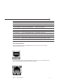
7110
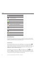
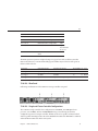
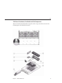
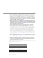
Introduction
This section describes concepts and procedural instructions for performing hardware and
software maintenance tasks. The graphic above illustrates locating a spare disk within the
chassis by highlighting its name in the BUI Hardware Maintenance list.The Maintenance >
Hardware screen of the BUI provides visual representations of the physical system components,
allowing you to visually identify and locate hardware components and verify their status.
Software Updates can be applied in the System section of the interface, as well as viewing Logs
and current Problems.
■
Hardware - identify hardware components and verify their status
■
7110 Hardware Overview - view component diagrams and specifications
■
7210 Hardware Overview - view component diagrams and specifications
■
7310 Hardware Overview - view component diagrams, specifications, and cluster options
■
7410 Hardware Overview - view component diagrams, specifications, and cluster options
■
7110, 7210, 7310, 7410 Maintenance Procedures - replace controller drives, fans, power
supplies, RAM, cards, risers, and batteries
■
Disk Shelf Overview - view component diagrams and specifications
■
Disk Shelf Maintenance Procedures - replace disk shelf components
■
System - view system disks, manage support bundles
■
Updates - manage appliance software updates
■
Configuration Backup - backup and restore appliance configuration
■
Problems - view current problems
■
Logs - view appliance logs
■
Workflows - manage and execute workflows
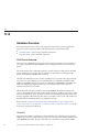
7110
Hardware Overview
Use the information in this section as a preparation reference for servicing replaceable
components of the 7110 system.
Refer to the following for procedural instructions:
■
■
26
Controller Tasks - replace system controller components
Disk Shelf Tasks - replace disk shelf components
Sun Storage 7000 Unified Storage System Service Manual • February 2010
7110
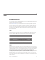
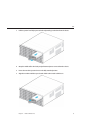
7110 Chassis Overview
The Sun Storage 7110 Unified Storage System is a rackmount x64 system powered by an AMD
Opteron processor. It packs high performance and room for growth with 6 PCIe slots and
16DIMM slots into a compact 2-RU footprint.
The 7110 is a unique product because it is self-contained. That is, the storage as well as the
processing function is contained within the server chassis itself. Refer to the
http://www.sun.com/storage/disk_systems/unified_storage/7110/specs.xml
(http://www.sun.com/storage/disk_systems/unified_storage/7110/specs.xml) for the
most recent component specification.
The supported configuration consists of either 16 internal 146GB 10K 2.5" SAS disk drives with
a total of 2TB or 16 internal 300GB 10K 2.5" SAS disk drives with a total of 4.2TB. Two drives
(disk # 0 & 1) will be used for the OS in a RAID 1 (mirror) and the remaining 14 drives are
available for storage.
The chassis has the following boards installed. Field-replaceable units (FRU) should only be
replaced by trained Sun service technicians.
7110 Boards
■
PCIe Risers - Each riser supports two PCIe cards that are customer-replaceable. There are
three risers per system, each attached to the rear of the motherboard.
■
Motherboard - The motherboard is a FRU and includes CPU modules, slots for 16 DIMMs,
memory control subsystems, and the service processor (SP) subsystem. The SP subsystem
controls the host power and monitors host system events (power and environmental). The
SP controller draws power from the hostâs 3.3V standby supply rail, which is available
whenever the system is receiving AC input power, even when the system is turned off.
■
Power Distribution Board - The power distribution board is a FRU and distributes main
12V power from the power supplies to the rest of the storage controller. It is directly
connected to the paddle card, and to the motherboard through a bus bar and ribbon cable. It
also supports a top cover interlock kill switch. The power supplies connect directly to the
power distribution board.
■
Paddle Card - The vertical power distribution board, or Paddle Card is FRU and serves as
the interconnect between the power distribution board and the fan power boards, hard drive
backplane, and I/O board.
■
Fan Power Boards - The two fan power boards are FRUs and carry power to the system fan
modules. In addition, they contain fan module status LEDs and transfer I2C data for the fan
modules.
■
Hard Drive Backplane - The hard drive backplane is a FRU and includes the connectors
for the hard disk drives, as well as the interconnect for the I/O board, Power and Locator
buttons, and system/component status LEDs. The system has a 16-disk backplane. Each
drive has an LED indicator for Power/Activity, Fault, and Identify.
Chapter 2 • Hardware Maintenance
27
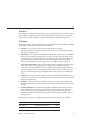
7110
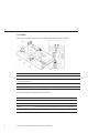
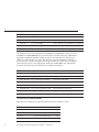
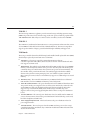
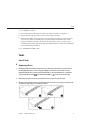
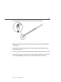
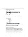
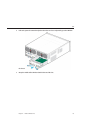
7110 Cables
The storage controller's internal cables are shown in the following figure and table.
Cable
Connection
1 Hard Drive Data Cables (2) Connections are between the HBA PCI-Express Card and the hard drive backplane.
2 Motherboard to Power
Distribution Board Cable
Connection is between the power distribution board and the motherboard.
3 PSU Backplane Cable
To the power supply units
4 Top Cover Interlock
Connected to the power distribution board.
The 2U chassis form factor dimensions are as follows:
28
Dimension
Measurement
Height
87.85 mm/3.46 in
Width
445.71 mm/17.55 in (includes rack ears; chassis is 425.46mm/16.75 in)
Depth
733.65 mm/28.88 in (includes PSU handle; the chassis is 711.25mm/28.00 in)
Weight
Maximum: 25.6 kg/56.3 lb
Sun Storage 7000 Unified Storage System Service Manual • February 2010
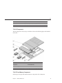
7110
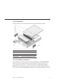
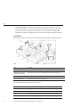
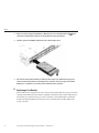
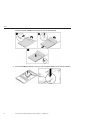
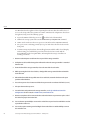
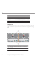
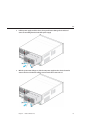
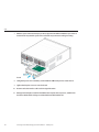
7110 I/O Components
The I/O components of the 7110 system are shown in the following figure and table.
Figure Legend
1 Top Cover
4 Left Control Panel Light Pipe Assembly (2)
2 Hard Disk Backplane 5 Hard Disk Drives
3 Hard Disk Cage
6 Left Control Panel Light Pipe Assembly
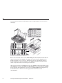
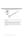
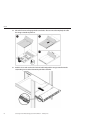
7110 CPU and Memory Components
The 7110 motherboard has 16 slots in two groups that hold industry-standard DDR2 DIMM
memory cards. The 7110 CPU and memory cards should only be replaced by field service
professionals. All sockets must be occupied by either a filler or a DDR2 DIMM. All DDR2
DIMMs must be the same density, (type and capacity). The Sun Storage 7110 Unified Storage
System supports the 4x2GB DDR2 DIMMs configuration. At minimum, Branch 0, Slot D6, and
Chapter 2 • Hardware Maintenance
29
7110
Slot D7 must be fully populated with DDR2 DIMMs of the same density.
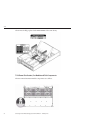
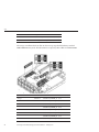
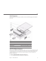
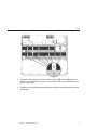
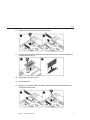
7110 Power Distribution, Fan Module and Disk Components
The Power Distribution/Fan Module components are as follows.
30
Sun Storage 7000 Unified Storage System Service Manual • February 2010
7110
Figure Legend
1 Paddle Card
4 Power Supplies
2 Power distribution board/bus bar assembly 5 Fan Modules
3 Paddle Card
7 Air Baffle
6 Fan Boards
Chapter 2 • Hardware Maintenance
31
7110
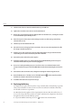
7110 PCIe Cards and Risers
Following is the set of guidelines for the 7110 risers. Note that internal HBA XATO
596-7055-01/371/3255/02 is located in slot 0.
Riser/Slot Numbers
Electrical Mechanical Source
Riser 0 - Slot 0 (internal SAS
HBA)
x8
x8
MCP55
Riser 0 - Slot 3
x8
x8
MCP55
Riser 1 - Slot 1
x8
x8
MCP55
Riser 1 - Slot 4
x8
x8
IO55
Riser 2 - Slot 2
x16
x16
IO55
Riser 2 - Slot 5
x4
x8
IO55
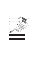
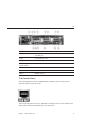
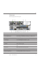
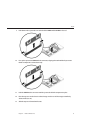
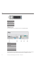
7110 Rear Panel
The following figure shows the rear panel. Note that optional Sun Dual Port 40Gb/sec 4x
Infiniband QDR HCAdapter PCIe cards (375-3606-01) may be located in slots 1, 2, or 3. Note
that 375-3606-01 HCA expansion cards are not supported in the 10Gb network configurations.
32
Sun Storage 7000 Unified Storage System Service Manual • February 2010
7110
Figure Legend
1 PSU 1
9 Rear panel System Status LEDs (locator:white; service action required:amber;
power/OK:green)
2 PSU 0
10 Serial Management Port
3 PCIe 3
11 Network Management Port
4 PCIe 0 (Occupied with
internal SAS HBA)
5 PCIe 4
6 PCIe 1
12 Gbit Ethernet Ports (0, 1, 2, 3)
7 PCIe 5
13 USB Ports (0, 1)
8 PCIe 2
14 HD15 Video Port
7110 Connector Pinouts
The serial management connector (SERIAL MGT) is an RJ-45 connector and provides a
terminal connection to the SP console.
The network management connector (NET MGT) is an RJ-45 connector on the motherboard
and provides an alternate terminal interface to the SP console.
Chapter 2 • Hardware Maintenance
33
7110
There are four RJ-45 Gigabit Ethernet connectors (NET0, NET1, NET2, NET3) located on the
motherboard that operate at 10/100/1000 Mbit/sec. These network interfaces must be
configured before use.
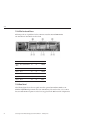
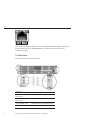
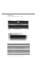
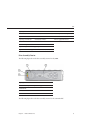
7110 Front Panel
The following figure shows the front panel.
Figure Legend
34
1 Locator LED/Locator
button (white)
5 Power Supply Service Required LED (amber)
2 Service Action Required
LED (amber)
6 System Overtemperature LED (amber)
3 power/OK LED (green)
7 Fan Module Service Required LED (amber)
4 Power button
8 Hard Disk Drive map
Sun Storage 7000 Unified Storage System Service Manual • February 2010
7110
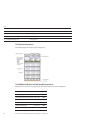
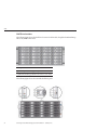
7110 Drive Locations
The following figure shows the drive locations.
Physical Hard Disk Drive Locations
HDD3
HDD7 N/A
HDD12 HDD15
HDD2
HDD6 N/A
HDD11 HDD14
HDD1
HDD5 HDD9 N/A
HDD0
HDD4 HDD8 HDD10 HDD13
N/A
7110 Configurations
The following table shows the configuration options for a single controller 7110. All PCIe cards
are low-profile, and must be fitted with low-profile mounting brackets. Note that 10Gb Ethernet
NIC cards must not be combined with 1Gb Ethernet NIC cards in the same system.
This table describes single base configurations for 7110.
Sun Mktg Part Number
Description
Mfg Part Number
TB7110-16ASA20
S7110, 1xCPU, 8GB, 2TB 597-0648-01
TB7110-16ASA42
S7110, 1xCPU, 8GB, 4.
597-0649-01
This table describes NIC HBA options for 7110.
Sun Mktg Part Number
Description
Mfg Part Number
SG-XPCIE2FC-QF4
2-port FC HBA, 4Gb, PCIe
594-2018-02
SG-XPCIE2FC-QF8-Z
2-port FC HBA, 8Gb, PCIe
594-5684-01
SGXPCIE2SCSIU320Z
2-port SCSI HBA, PCIe
594-2019-04
X7280A-2
2-port 10/100/1000 NIC, PCIe
594-1755-04
X7281A-2
2-port MMF (Optical) NIC, PCIe 594-1756-03
Chapter 2 • Hardware Maintenance
35
7110
Sun Mktg Part Number
Description
Mfg Part Number
X4446A-Z
4-port PCIe Quad GigE UTP
594-4024-01
X4237A
2-port 4X IB HCA PCIe
594-4110-03
X1027A-Z
2-port 10Gig NIC, PCIe
594-4110-03
This table describes the supported PCIe configuration option summary for 7110 (without
10GigE cards).
Slot
Slot Type Sun Part Number Vendor Part Number
Description
Note
0
PCIe
371-3255-03
LSI 1068E
Internal SAS HBA Base Configuration
1
N/A
N/A
N/A
N/A
Not Used
2
PCIe
371-0905-04
Intel EXPI9402PT
DP Copper NIC
Optional Allowed Alternative
2
PCIe
371-0904-03
Intel EXPI9402PF
DP Optical NIC
Optional Allowed Alternative
2
PCIe
375-3481-01
Intel EXPI9404PT
QP Copper NIC
Optional Recommended Front-end
2
PCIe
375-3606-02
Sun Dual Port 40Gb/sec 4x Infiniband HCA
Optional Recommended Front-end
2
PCIe
371-4325-01
QLogic
8Gb DP FC HBA
Optional FC Target or Initiator (Backup)
3
PCIe
371-0905-04
Intel EXPI9402PT
DP Copper NIC
Optional Allowed Alternative
3
PCIe
371-0904-03
Intel EXPI9402PF
DP Optical NIC
Optional Allowed Alternative
3
PCIe
375-3481-01
Intel EXPI9404PT
QP Copper NIC
Additional Optional Recommended Front-end
3
PCIe
375-3606-02
Sun Dual Port 40Gb/sec 4x Infiniband QDR
Optional Recommended Front-end
3
PCIe
371-4325-01
QLogic
8Gb DP FC HBA
Optional FC Target or Initiator (Backup)
4
PCIe
371-0905-04
Intel EXPI9402PT
DP Copper NIC
Optional Allowed Alternative
4
PCIe
371-0904-03
Intel EXPI9402PF
DP Optical NIC
Optional Allowed Alternative
4
PCIe
375-3481-01
Intel EXPI9404PT
QP Copper NIC
Optional Recommended Front-end
4
PCIe
375-3606-02
Sun Dual Port 40Gb/sec 4x Infiniband QDR
Optional Recommended Front-end
4
PCIe
371-4325-01
QLogic
8Gb DP FC HBA
Optional FC Target or Initiator (Backup)
5
PCIe
375-3357-05
LSI LSI22320SLE
DP SCSI HBA
Optional (Tape BU)
This table describes the supported PCIe configuration option summary for 7110 (with 10GigE
cards).
36
Sun Storage 7000 Unified Storage System Service Manual • February 2010
7210
Slot
Slot Type Sun Part Number Vendor Part Number
Description
Note
0
PCIe
371-3255-03
LSI 1068E
Internal SAS HBA
Base Configuration
1
N/A
N/A
N/A
N/A
Not used
2
PCIe
501-7283-07
Sun
DP Optical 10GE NIC Additional Optional Recommended Front-end
3
PCIe
501-7283-07
Sun
DP Optical 10GE NIC Additional Optional Recommended Front-end
4
N/A
N/A
N/A
N/A
5
PCIe
375-3356-02
QLogic QLE2462L DP 4Gb FC HBA
Optional (Tape BU)
5
PCIe
375-3357-05
LSI LSI22320SLE
Optional (Tape BU)
DP SCSI HBA
Not used
See Also
■
Controller Details
7210
Hardware Overview
Use the information on this page as a preparation reference for servicing replaceable
components of the 7210 system. Refer to the following for procedural instructions:
■
■
Controller Tasks - replace system controller components
Disk Shelf Tasks - replace disk shelf components
7210 Chassis Overview
The Sun Storage 7210 Unified Storage System provides the following maximum configurations:
■
Sixteen DDR2 DIMM slots (8 per processor) 64GB maximum with two CPUs and 4GB
DIMMs, standard 32GB
■
Up to forty-eight 3.5-inch SATA-II drives of 250GB - 1TB capacity (48TB total system
capacity)
■
Three x8 PCIe slots
■
Up to two Solid State Drives 18GB 3.5" SATA
Refer to the http://www.sun.com/storage/disk_systems/unified_storage/7210/specs.xml
(http://www.sun.com/storage/disk_systems/unified_storage/7210/specs.xml) for the
most recent component specification.
Chapter 2 • Hardware Maintenance
37
7210
7210 Front Panel
The following figures show the front panel and controls.
# Name
Description
1 Locate button/LED
Remote On. Press to turn off.
2 System Fault
When on, service action is required
3 Power Operation
Steady: On, Blink:Standby; Off: Power is off
4 System power button
Automated power on by default
5 Top failure LED
On - HDD or fan fault
6 Rear failure LED
On - Power supply or system controller fault (service required)
7 Over Temperature LED When on, the system is over temperature.
38
Sun Storage 7000 Unified Storage System Service Manual • February 2010
7210
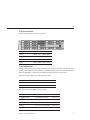
7210 Rear Panel
The following figure shows the rear panel.
#
Name
Description
1
Power Supply Fault LED (amber)
On: service action required
2
Power Supply LED (green)
Steady: AC/DC power OK; Blinking: AC Standby power on; Off: Power is off
3
AC power connectors
Each power supply has its own AC connector with a clip to secure its cable
4
Chassis ground
Connect grounding straps
5
Mounting plate
To secure Cable Management Arm (CMA) - optional
6
PCIe
Three slots for PCIe cards
7
Locate button/LED (white)
Remote On, press to turn off
8
Fault LED
Amber: service action required
9
OK LED
Green: power is on; Off: system power is off; Blink: power connected but host system
is off
10 Reset buttons
Only use when directed by Sun service personnel
11 System controller status LEDs
Blue:service action allowed; Amber:faulted, action required; Green: operational
12 Serial management port
Serial connection to service processor
13 Network management port
10/100 Mbit/sec Ethernet connection to service processor
14 Gigabit (10/100/1000 Mbit/sec) Ethernet ports To connect system to Ethernet
Chapter 2 • Hardware Maintenance
39
7210
#
Name
Description
15 USB connectors
Not supported
16 Video connector
Not supported
17 Compact Flash (CF) card
Not supported
7210 System Components
The following figure shows the system components.
7210 Additional Options and Replaceable Components
Following are the after-factory options and replaceable components of the 7210 system.
40
Component
Mktg Part Number FRU/CRU
Power Supply (2 PS/system)
#300-1787
CRU
Fan Module (5 fan modules/system) #341-0458
CRU
Seagate Galaxy 250GB
#541-1468
CRU
Hitachi GeminiK 500GB
#541-3050
CRU
Hitachi GeminiK 1TB
#540-7507
CRU
Seagate 250GB ST3250310NS
#541-3678
CRU
Sun Storage 7000 Unified Storage System Service Manual • February 2010
7210
Component
Mktg Part Number FRU/CRU
Seagate 500GB ST3500320NS
#541-3679
CRU
Seagate 1TB ST31000340NS
#541-3730
CRU
2 DIMMs x 2GB DIMMS (4GB
total) Registered ECC Memory, 16
slots/system
#541-1313
X5034
(X-Option)
CRU
2 DIMMs x 4GB DIMMS (8GB
total) Registered ECC Memory, 16
slots/system
#541-1304
X5035
(X-Option)
CRU
System Controller Assembly (I/O
controller and CPU boards)
#541-0491 without CPUs
FRU
CPU (quad core 2356 processor)
#371-4042
FRU
Sun Dual Port 40Gb/sec 4x
Infiniband QDR HCA, PCIe
#375-3606-01
FRU
QLogic 8Gb DP FC HBA
#371-4325-01
FRU
Front Indicator Board (FIB) with
ribbon cable
#501-7192
FRU
System Enclosure Super (disk
backplane and FIB with ribbon
cable)
#541-1907-01
FRU
Power Distribution Board
#501-7104
FRU
Cable Management Arm
#371-2887-01
CRU
Slide Rail Kit
#371-3493-01
CRU
Solid State Drive 18 GB 3.5" SATA
#540-7350-01
CRU
As an option, the 7210 offers expanded storage up to 144 TB using a maximum of two J4500
disk shelves via an external SAS HBA card, Sun part # 594-4098-04 (PTO), 596-6707-04 (ATO)
and 4X Mini SAS Shielded Cables.
See Also
For step-by-step information about how to replace components refer to the following sections:
■
■
Controller Details
Disk Shelf Details
Chapter 2 • Hardware Maintenance
41
7310
7310
Hardware Overview
Use the information in this section as a preparation and reference for servicing replaceable
components of the 7310 system. Refer to the following for procedural instructions:
■
■
Controller Tasks - replace storage controller components
Disk Shelf Tasks - replace disk shelf components
7310 Chassis Overview
The Sun Storage 7310 Unified Storage System consists of either a single storage controller, or
two storage controllers in a high availability cluster configuration, and one to four Sun disk
shelves.
The 7310 controller base configuration includes one CPU, built-in 4 x 1Gb/s Front-end GigE
ports, redundant power supplies, NIC Card options for expanded front-end support, tape
backup, and Dual Port SAS HBA for the backend.
The CPU is an AMD Opteron Six-core 2427 2.2GHz processor. Systems can be upgraded with
second Six-core 2427 2.2GHz processor. Standard Memory configuration is16GB, 4 x 4GB
DDR2-667 SR DIMMs and may be upgraded to 64GB using 16x4GB DDR2-667 DIMMs. The
Clustered configuration simply uses two servers and a Cluster Card in each server for a
heartbeat connection between them.
All user accessible storage is provided by one to four J4400/Sun Disk shelves external to the
server(s). The RAID function is done by the software. Solid State 18GB 3.5" SATA drives (7310
SAS-1) and 18GB SAS-1 drives (7310 SAS-2) which are used for high performance write cache
known as LogZilla or ZFS intent log (ZIL) devices, are in place of one to four of the 24 drives in
the Disk Shelf, the remaining 20 drives are available for storage.
Refer to the http://www.sun.com/storage/disk_systems/unified_storage/7310/specs.xml
(http://www.sun.com/storage/disk_systems/unified_storage/7310/specs.xml) for the
most recent component specification.
7310 SAS-1
The Sun Storage 7310 SAS-1 appliance provides external storage, including expansion, using
J4400 storage enclosures. These enclosures support the SAS-1 protocol and are populated with
1TB 7200 RPM SATA disks. They are connected to the controller(s) via the SAS-1 LSI HBA.
42
Sun Storage 7000 Unified Storage System Service Manual • February 2010
7310
7310 SAS-2
The 7310 SAS-2 (Serial Attached SCSI 2.0) moves to a next generation architecture that consists
of a new HBA, new disk shelf, and new disks (1TB and 2TB SAS-2). The SAS-2 storage fabric
supports greater number of targets, greater bandwidth, higher reliability and bigger scale.
7310 Boards
The storage controller chassis has the following boards installed. Field-replaceable units (FRUs)
should only be replaced by trained Sun service technicians.
■
PCIe Risers - The storage controller contains three PCIe risers that are
customer-replaceable units (CRUs) and are attached to the rear of the motherboard. Each
riser supports one PCIe card.
■
Motherboard - The motherboard is a FRU and includes CPU modules, slots for 16 DIMMs,
memory control subsystems, and the service processor (SP) subsystem. The SP subsystem
controls the host power and monitors host system events (power and environmental). The
SP controller draws power from the hostâs 3.3V standby supply rail, which is available
whenever the system is receiving AC input power, even when the system is turned off.
■
Power Distribution Board - The power distribution board is a FRU and distributes main
12V power from the power supplies to the rest of the storage controller. It is directly
connected to the Vertical PDB card, and to the motherboard through a bus bar and ribbon
cable. It also supports a top cover interlock kill switch. In the storage controller, the power
supplies connect to the power supply backplane which connects to the power distribution
board.
■
Paddle Card - The vertical power distribution board, or Paddle Card is a FRU and serves as
the interconnect between the power distribution board and the fan power boards, hard drive
backplane, and I/O board.
■
Fan Boards - The two fan boards are FRUs and carry power to the storage controller fan
modules. In addition, they contain fan module status LEDs and transfer I2C data for the fan
modules.
■
Hard Drive Backplane - The hard drive backplane is a FRU and includes the connectors
for the hard disk drives, as well as the interconnect for the I/O board, Power and Locator
buttons, and system/component status LEDs. The storage controller has an eight-disk
backplane. Each drive has an LED indicator for Power/Activity, Fault, and OK-to-remove
(not supported).
Following is the complete set of replaceable system boards for the 7310 storage controller.
Part Number
Description
FRU/CRU
F541-2128-04
X8-XAUI PCIe Riser Card 1U
CRU
F541-2298-02
X16 SWIZ PCIe Riser Card 1U
CRU
Chapter 2 • Hardware Maintenance
43
7310
Part Number
Description
FRU/CRU
F541-2297-08
RoHS Galaxy 2N Motherboard and Tray FRU
F501-7696-09
DB, Power Distribution Board
FRU
F501-7797-05
PCB, 8 Disk 1U Backplane
FRU
F541-2183-05
PCBA, Connector Board, 1U
FRU
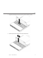
7310 Cables
The storage controller's internal cables are shown in the following figure and described in the
table.
Cable
Connection
1 SATA Hard Drive Data
Cables
Connections are between the motherboard SATA connections and the hard disk
backplane. Note that the X Connector must be placed before the 0 Connector.
2 Motherboard to Power
Distribution Board Cable
Connection is between the power distribution board and the motherboard.
3 Top Cover Interlock
Connected to the power distribution board.
Following is the complete set of replaceable cables for the 7310 storage controller.
44
Part Number
Description
FRU/CRU
F540-7609-01
Cable, Mini SAS/SATA RT G1N2 2U
FRU (internal)
F530-3927-01
FRU,CBL,PDB,MB,1U+2U,RIBBON
FRU (internal)
Sun Storage 7000 Unified Storage System Service Manual • February 2010
7310
Part Number
Description
FRU/CRU
F530-3880-01
Cable, Assembly, Ethernet, Shielded, RJ45-RJ45, 6m CRU (external)
F530-3883-01
FRU,2M,4X MINI SAS CBL,SHLD
CRU (external)
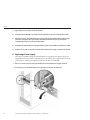
7310 I/O Components
The I/O components of the storage controller are shown in the following figure and identified
in the table.
Figure Legend
1 Top Cover
4 Solid State Drives
2 Hard Disk Cage
5 Hard Disk Drives
3 Left Control Panel Light Pipe Assembly 6 Right Control Panel Light Pipe Assembly
7310 CPU and Memory Components
Following are the replaceable CPU and memory components of the 7310 system.
Chapter 2 • Hardware Maintenance
45
7310
Part Number
Description
FRU/CRU
F540-7600-01
RoHS Memory 2 x 4GB (371-3847-01)
CRU
F371-4042-01
AMD, Opteron 2356 Quad-core 2.3GHz FRU
The storage controller motherboard has 16 slots in two groups that hold industry-standard
DDR2 DIMM memory cards. All sockets must be occupied by either a filler or a DDR2 DIMM.
Branch Number
Channel Number Address
Group 0
Channel A
Motherboard Connector
/SYS/Memory/DIMM_A0 J1001
/SYS/Memory/DIMM_A1 J1101
/SYS/Memory/DIMM_A2 J1101
/SYS/Memory/DIMM_A3 J1101
Channel B
/SYS/Memory/DIMM_B0 J1201
/SYS/Memory/DIMM_B1 J1301
/SYS/Memory/DIMM_B2 J1301
/SYS/Memory/DIMM_B3 J1301
46
Sun Storage 7000 Unified Storage System Service Manual • February 2010
7310
Branch Number
Channel Number Address
Group 1
Channel C
Motherboard Connector
/SYS/Memory/DIMM_C0 J1001
/SYS/Memory/DIMM_C1 J1101
/SYS/Memory/DIMM_C2 J1101
/SYS/Memory/DIMM_C3 J1101
Channel D
/SYS/Memory/DIMM_D0 J1201
/SYS/Memory/DIMM_D1 J1301
/SYS/Memory/DIMM_D2 J1301
/SYS/Memory/DIMM_D3 J1301
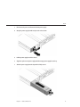
7310 Power Distribution, Fan Module and Disk Components
The Power Distribution/Fan Module components of the storage controller are shown in the
following figure and identified in the table.
Figure Legend
1 Power Distribution Board/Bus Bar Assembly 4 Power Supplies
Chapter 2 • Hardware Maintenance
47
7310
Figure Legend
2 Paddle Card
5 Fan Modules
3 Air Baffle
6 Fan Boards
7310 Drive Locations
Two mirrored hard disk drives (HDDs) that store the operating system reside in slots 6 and 7.
Up to six solid state drives (ReadZilla SSDs) that store the read cache fill slots 0 through 5, in
order.
Following is the complete list of replaceable power distribution, disk, and fan module
components of the 7310 system. Note that power supplies, disks, and fan modules are
hot-pluggable on the storage controller.
Part Number
Description
FRU/CRU
F300-2015-05
RoHS 650W Power Supply
CRU
F540-7711-01
2.5" 500GB 5400rpm SATA HDD CRU
F540-7793-01
2.5" 100GB ReadZilla SSD
CRU
F541-2802-03
FAN CPU,1U J+
CRU
F541-2112-03
Fan Board (1U)
FRU
7310 SAS-1 PCIe Cards and Risers
Following is the complete list of replaceable PCIe cards for the 7310 SAS-1 system.
48
Part Number
Description
FRU/CRU
F375-3356-02
Fibre Channel (PCIe)
CRU
F371-4325-01
Dual Port 8Gb FC HBA (PCIe)
CRU
F375-3487-05
Dual Port SAS (x4) HBA (PCIe)
CRU
F371-0905-04
NIC Card Dual Port 1GigE Cu (PCIe)
CRU
Sun Storage 7000 Unified Storage System Service Manual • February 2010
7310
Part Number
Description
FRU/CRU
F371-0904-03
NIC Card Dual Port 1GigE Fiber (PCIe) CRU
F375-3481-01
NIC Card Quad Port 1GigE Cu (PCIe)
CRU
F501-7283-07
NIC Card Dual Port 10GigE (PCIe)
CRU
F375-3606-02
InfiniBand HCA
Optional
Recommended
Front-end
F371-3024-01
Sun Fishworks Cluster Controller 100
(PCIe)
FRU
The PCIe expansion system is configured using two types of riser cards, as follows. Note that
PCIe cards with x4, x8, or x16 mechanical finger pins will fit in any riser slot but will operate at
the lane width of the slot.
Location: Type
Cards (Single Controller)
Cards (Clustered Controllers)
PCIe Lane Width Size Source
Slot: 0 Type:1
Optional tape backup HBA Cluster card
x8
x8
MCP55
Slot:1 Type:1
SAS HBA
SAS HBA
x8
x8
MCP55
Slot:1 Type:2
Optional NIC
Optional NIC or tape backup HBA x4
x8
IO55
7310 SAS-1 Rear Panel
Following is an illustration of the 7310 SAS-1 storage controller rear panel.
7310 SAS-1 Single and Cluster Controller Configurations
The 7310 SAS-1 single controller base configuration is 16GB RAM, 1x2.3GHz Quad-Core
processor, one SAS HBA, and four 10/100/1000 Ethernet ports. Following are the PCIe
configuration options for a single controller. All PCIe cards are low-profile, and must be fitted
with low-profile mounting brackets. Note that 10Gb Ethernet NIC cards must not be combined
with 1Gb Ethernet NIC cards in the same system.
Chapter 2 • Hardware Maintenance
49
7310
Slot Part Number
Description
Note
0
QLogic QLE2462L Two-port 4Gb Fibre Channel HBA
Optional tape backup HBA
0
LSI LSI22320SLE
Two-port SCSI HBA
Optional tape backup HBA
1
LSI 3801E
Two-port SASx4 HBA
Storage shelf connector, included in base configuration
2
Intel EXPI9404PT Four-port 1Gb Copper Ethernet NIC
2
Sun 375-3606-01
Optional NIC, recommended
Dual Port 40Gb/sec 4x Infiniband QDR Host Channel Adapter PCI Express, RoHS:Y
The 7310 SAS-1 cluster base configuration is 16GB RAM, 1x2.3GHz Quad-Core processor, one
SAS HBA, four 10/100/1000 Ethernet ports, and a Cluster card. The Sun Storage 7410C Cluster
Upgrade Kit (XOPT 594-4680-01) contains two cluster cards with cables for converting two
7310 or two 7410 controllers to a cluster. The following options are available for 7310 SAS-1
clustered storage controllers. Note that both storage controllers in a cluster must be configured
identically with regard to card configurations and all optional NIC/HBA card configurations
chosen for clustered storage controllers must be identical in both chassis.
Slot Part Number
Description
Note
0
Sun 371-3024-01
Sun Fishworks Cluster Controller 100
Cluster card, included in base configuration
1
LSI 3801E
Two-port SASx4 HBA
Storage shelf connector, included in base configuration
2
QLogic QLE2462L Two-port 4Gb Fibre Channel HBA
Optional tape backup HBA
2
Intel EXPI9404PT Four-port 1Gb Copper Ethernet NIC
Optional NIC, recommended
2
Sun X1027A-Z
Optional NIC, recommended
2
Intel EXPI9402PT Two-port 1Gb Copper Ethernet NIC
Optional NIC, allowed alternative
2
Intel EXPI9402PF Two-port 1Gb Optical Ethernet NIC
Optional NIC, allowed alternative
2
Sun 375-3606-01
Two-port 10Gb Optical Ethernet NIC
Dual Port 40Gb/sec 4x Infiniband QDR Host Channel Adapter PCI Express, RoHS:Y
7310 SAS-2 PCIe Cards and Risers
Following is the complete list of replaceable PCIe cards for the 7310 SAS-2 system.
50
Part Number
Description
FRU/CRU
F375-3357-05
Dual U320 SCSI (PCIe)
CRU
F375-3356-02
Dual Port 4Gb FC HBA (PCIe)
CRU
F371-4325-01
Dual Port 8Gb FC HBA (PCIe)
CRU
F375-3487-04
Dual Port SAS (x4) HBA (PCIe)
CRU
Sun Storage 7000 Unified Storage System Service Manual • February 2010
7310
Part Number
Description
FRU/CRU
F371-0905-04
NIC Card Dual Port 1GigE Cu (PCIe) CRU
F371-0904-03
NIC Card Dual Port 1GigE Fiber
(PCIe)
CRU
F375-3481-01
NIC Card Quad Port 1GigE Cu
(PCIe)
CRU
F501-7283-07
NIC Card Dual Port 10GigE (PCIe)
CRU
F371-3024-01
Sun Fishworks Cluster Controller
100 (PCIe)
FRU
The PCIe expansion system is configured using two types of riser cards, as follows. Note that
PCIe cards with x4, x8, or x16 mechanical finger pins will fit in any riser slot but will operate at
the lane width of the slot.
Location: Type
Cards (Single Controller)
Cards (Clustered Controllers)
PCIe Lane Width Size Source
Slot: 0 Type:1
Optional tape backup HBA Cluster card
x8
x8
MCP55
Slot:1 Type:1
SAS HBA
SAS HBA
x8
x8
MCP55
Slot:1 Type:2
Optional NIC
Optional NIC or tape backup HBA x4
x8
IO55
7310 SAS-2 Rear Panel
Following is an illustration of the 7310 SAS-2 storage controller rear panel. The Sun 375-3609
belongs in slot 1 (number 11 in the diagram), cannot be installed in any other slots, and a
second is not offered as an option.
Figure Legend
1 Power Supplies
7 Ethernet ports
Chapter 2 • Hardware Maintenance
51
7310
Figure Legend
2 Locator LED button
8 USB ports (not for use)
3 Service Required LED 9 VGA video port (not for use)
4 Power OK LED
10 Cluster Card (cluster
config. only)
5 Serial management
port
11 HBA
6 Network
management port
7310 SAS-2 Single and Cluster Controller Configurations
The single controller base configuration is 16GB RAM, 1x2.3GHz Quad-Core processor, one
SAS HBA, and four 10/100/1000 Ethernet ports. Following are the PCIe configuration options
for a single controller. All PCIe cards are low-profile, and must be fitted with low-profile
mounting brackets. Note that 10Gb Ethernet NIC cards must not be combined with 1Gb
Ethernet NIC cards in the same system.
Slot Part Number
Description
Note
0
QLogic QLE2462L Two-port 4Gb Fibre Channel HBA
Optional tape backup HBA
0
LSI LSI22320SLE
Two-port SCSI HBA
Optional tape backup HBA
0
Sun 371-4325-01
Two-port FC HBA, 8Gb, PCIe
Optional FC Target or Initiator (Backup)
1
Sun 375-3609
Two-port SASx4 HBA
Storage shelf connector, included in base configuration
2
Intel EXPI9404PT Four-port 1Gb Copper Ethernet NIC
2
Sun 375-3606-01
Dual Port 40Gb/sec 4x Infiniband QDR Host Channel Adapter PCI Express, RoHS:Y
2
PCIe
371-4325-01
Optional NIC, recommended
QLogic
8Gb DP FC HBAOptional FC Target or Initiator (B
The 7310 SAS-2 cluster base configuration is 16GB RAM, 1x2.3GHz Quad-Core processor, one
SAS HBA, four 10/100/1000 Ethernet ports, and a Cluster card. The Sun Storage 7410C Cluster
Upgrade Kit (XOPT 594-4680-01) contains two cluster cards with cables for converting two
7310 or two 7410 controllers to a cluster. The following options are available for clustered
storage controllers. Note that both storage controllers in a cluster must be configured
identically with regard to card configurations and all optional NIC/HBA card configurations
chosen for clustered storage controllers must be identical in both chassis.
52
Sun Storage 7000 Unified Storage System Service Manual • February 2010
7310
Slot Part Number
Description
Note
0
Sun 371-3024-01
Cluster controller 100
Cluster card, included in base configuration
1
Sun 375-3609
Two-port SASx4 HBA
Storage shelf connector, included in base configuration
2
QLogic QLE2462L Two-port 4Gb Fibre Channel HBA
Optional tape backup HBA
2
Intel EXPI9404PT Four-port 1Gb Copper Ethernet NIC
Optional NIC, recommended
2
LSI LSI22320SLE
Two-port SCSI HBA
Optional tape backup HBA
2
Sun X1027A-Z
Two-port 10Gb Optical Ethernet NIC
Optional NIC, recommended
2
Intel EXPI9402PT Two-port 1Gb Copper Ethernet NIC
Optional NIC, allowed alternative
2
Intel EXPI9402PF Two-port 1Gb Optical Ethernet NIC
Optional NIC, allowed alternative
2
Sun 375-3606-01
Dual Port 40Gb/sec 4x Infiniband QDR Host Channel Adapter PCI Express, RoHS:Y
2
371-4325-01
QLogic 8Gb DP FC HBA
Optional FC Target or Initiator (Backup)
7310 Connector Pinouts
The serial management connector (SERIAL MGT) is an RJ-45 connector and a terminal
connection to the SP console.
The network management connector (NET MGT) is an RJ-45 connector on the motherboard
and provides an alternate terminal interface to the SP console.
Chapter 2 • Hardware Maintenance
53
7410
There are four RJ-45 Gigabit Ethernet connectors (NET0, NET1, NET2, NET3) located on the
motherboard that operate at 10/100/1000 Mbit/sec. These network interfaces must be
configured before use.
7310 SAS-1 Storage Disk Shelf
The user-accessible storage for the 7310 system is provided by one to four J4400/Sun disk
shelves. Typically a shelf is fully-populated with 24 drives unless only one shelf is used, in which
case the shelf may be half-populated with 12 drives. Expanding beyond one shelf requires that
all shelves are fully-populated with 24 drives each.
7310 SAS-2 Storage Disk Shelf
The 7310 single and cluster controller configurations allow a single chain of 1 to 4 Sun Disk
Shelves. Any combination of disk-only and Logzilla-capable shelves may be combined within
the chain in any order. The cabling configurations are unchanged. Half-populated shelf
configurations are not supported for SAS-2.
See Also
■
■
■
Disk Shelf Overview
Disk Shelf Details
Controller Details
7410
Hardware Overview
Use the information on this page as a preparation reference for servicing replaceable
components of the 7410 system. Refer to the following for procedural instructions:
■
■
Controller Tasks - replace system controller components
Disk Shelf Tasks - replace disk shelf components
7410 Chassis Overview
The Sun Storage 7410 Unified Storage System consists of either a single storage controller, or
two storage controllers in a high availability cluster configuration, and one to twelve Sun disk
shelves. Refer to the http://www.sun.com/storage/disk_systems/unified_storage/7410/
specs.xml (http://www.sun.com/storage/disk_systems/unified_storage/7410/
specs.xml) for the most recent component specification.
54
Sun Storage 7000 Unified Storage System Service Manual • February 2010
7410
7410 SAS-1
The Sun Storage 7410 SAS-1 appliance provides external storage, including expansion, using
J4400 storage enclosures. These enclosures support the SAS-1 protocol and are populated with
1TB 7200 RPM SATA disks. They are connected to the controller(s) via the SAS-1 LSI HBA.
7410 SAS-2
The 7410 SAS-2 (Serial Attached SCSI 2.0) moves to a next generation architecture that consists
of a new HBA, new disk shelf, and new disks (1TB and 2TB SAS-2). The SAS-2 storage fabric
supports greater number of targets, greater bandwidth, higher reliability and bigger scale.
7410 Boards
The storage controller chassis has the following boards installed. Field-replaceable units (FRUs)
should only be replaced by trained Sun service technicians.
■
PCIe Risers - The storage controller contains three PCIe risers that are
customer-replaceable units (CRUs) and are attached to the rear of the motherboard. Each
riser supports two PCIe cards.
■
Motherboard - The motherboard is a FRU and includes CPU modules, slots for 16 DIMMs,
memory control subsystems, and the service processor (SP) subsystem. The SP subsystem
controls the host power and monitors host system events (power and environmental). The
SP controller draws power from the hostâs 3.3V standby supply rail, which is available
whenever the system is receiving AC input power, even when the system is turned off.
Hyper-transport connector slots to a mezzanine tray support two additional processors and
memory.
■
Mezzanine Tray - The removable mezzanine tray is a FRU and includes two additional
CPU modules, slots for 16 DIMMs, and memory control subsystems.
■
Power Distribution Board - The power distribution board is a FRU and distributes main
12V power from the power supplies to the rest of the system. It is directly connected to the
Vertical PDB card, and to the motherboard through a bus bar and ribbon cable. It also
supports a top cover interlock (âkillâ) switch. In the storage controller, the power
supplies connect to the power supply backplane which connects to the power distribution
board.
■
Vertical PDB Card - The vertical power distribution board, or Paddle Card is a FRU and
serves as the interconnect between the power distribution board and the fan power boards,
hard drive backplane, and I/O board.
■
Power Supply Backplane Card - This board connects the power distribution board to
power supplies 0 and 1.
■
Fan Power Boards - The two fan power boards are FRUs and carry power to the storage
controller fan modules. In addition, they contain fan module status LEDs and transfer I2C
data for the fan modules.
Chapter 2 • Hardware Maintenance
55
7410
■
Hard Drive Backplane - The hard drive backplane is a FRU and includes the connectors
for the hard disk drives, as well as the interconnect for the I/O board, Power and Locator
buttons, and system/component status LEDs. The storage controller has an eight-disk
backplane. Each drive has an LED indicator for Power/Activity, Fault, and Ok-To-Remove.
7410 Cables
The storage controller's internal cables are shown in the following figure and described in the
table.
Cable
Connection
1 Hard Drive Data Cables (2) Connections are between the HBA PCI-Express Card and the hard drive backplane.
2 Motherboard to Power
Distribution Board Cable
Connection is between the power distribution board and the motherboard.
3 PSU Backplane Cable
To the power supply units
4 Top Cover Interlock
Connected to the power distribution board.
The 2U chassis form factor dimensions are as follows:
56
Dimension
Measurement
Height
87.85 mm/3.46 in
Width
445.71 mm/17.55 in (includes rack ears; chassis is 425.46 mm/16.75 in)
Depth
733.65 mm/28.88 in (includes PSU handle; the chassis is 711.25 mm/28.00 in)
Weight
Maximum: 25.6 kg/56.3 lbs
Sun Storage 7000 Unified Storage System Service Manual • February 2010
7410
7410 I/O Components
The I/O components of the storage controller are shown in the following figure and identified
in the table.
Figure Legend
1 Top Cover
5 ReadZilla Solid State Drives (SSDs) (6)
2 Hard Disk Backplane
6 Hard Disk Drives (HDDs) (2)
3 Hard Disk Cage
7 Right Control Panel Light Pipe Assembly
4 Left Control Panel Light Pipe Assembly
7410 CPU and Memory Components
Memory is pre-configured on the 7410 system. There are 32 slots: 16 on the mezzanine tray, and
16 on the motherboard, in four branches, that hold industry-standard DDR2 DIMM modules.
All DDR2 DIMMs must be the same density (type and capacity). The system supports the
following configurations:
■
■
From: 8 x 2GB DDR2 DIMMs (minimum configuration)
To: 32 x 8GB DDR2 DIMMs (fully populated configuration)
Chapter 2 • Hardware Maintenance
57
7410
At minimum, Branch 0 must be fully populated with two DDR2 DIMMs of the same density
(same type).
Refer to the service label on the cover for DDR2 DIMM placement information. Each CPU can
support a maximum of eight DIMMs. The DIMM slots are paired and the DIMMs must be
installed in pairs (0-1, 2-3, 4-5, and 6-7). The memory sockets are colored black or white to
indicate which slots are paired by matching colors. DIMMs are populated starting from the
outside (away from the CPU) and working toward the inside.
CPUs with only a single pair of DIMMs must have those DIMMs installed in that CPU's outside
white DIMM slots (6 and 7). Only DDR2 667 MHz DIMMs are supported. Each pair of DIMMs
must be identical (same manufacturer, size, and speed). DDR2 DIMM names in appliance logs
and the Maintenance > Hardware view are displayed with the full name, such as
/SYS/MB/P0/D7.
58
Sun Storage 7000 Unified Storage System Service Manual • February 2010
7410
7410 Power Distribution, Fan Module and Disk Components
The Power Distribution/Fan Module components of the storage controller are shown in the
following figures and identified in the table.
Chapter 2 • Hardware Maintenance
59
7410
Figure Legend
1 Paddle Card
5 Fan Modules
2 Power distribution board/bus bar assembly 6 Fan Boards
3 PSU Backplane
7 Air Baffle
4 Power Supplies
8 Mezzanine Tray
7410 Drive Locations
The 500GB Boot Drives (HDDs) reside in slots 6 and 7 as a mirrored set, and the Sun Storage
ReadZilla Flash 2.5" 100GB solid state drives (SSD's), will fill in order, slots 0 through 5. You can
have a maximum of 6 Sun Storage ReadZilla Flash SSD's.
Physical Drive Locations
SSD1
SSD3 SSD5
SSD0
SSD2 SSD4 HDD6 HDD7
7410 SAS-1 Rear Panel
The following graphic shows the 7410 SAS-1 rear panel. The 7410 SAS-1 PCIe expansion
system is configured using two types of riser cards, as follows. Note that PCIe cards with x4, x8,
or x16 mechanical finger pins will fit in any riser slot but will operate at the lane width of the
slot. The Cluster Controller 100 (MFG Part #371-30224-01) belongs in PCIe slot 5. The SAS
HBAs must all be of the same type and belong in slots 1 and slot 0.
60
Sun Storage 7000 Unified Storage System Service Manual • February 2010
7410
Figure Legend
1 Power supplies
7 Ethernet ports
2 Locator LED button
8 USB ports
3 Service Required LED
9 VGA video port
4 Power OK LED
10 HBAs
5 Serial management port
11
6 Network management port
7410 SAS-2 Rear Panel
The following graphic shows the 7410 SAS-2 rear panel.
Figure Legend
1 Power supplies
7 Ethernet ports
2 Locator LED button
8 USB ports
Chapter 2 • Hardware Maintenance
61
7410
Figure Legend
3 Service Required LED
9 VGA video port
4 Power OK LED
10 HBAs (slot 0 is optional only)
5 Serial management port
11
only)
6 Network management port
7410 SAS-2 PCIe Cards and Risers
operate at the lane width oft he slot. The Cluster Controller 100 (MFG Part #371-30224-01)
belongs in PCIe slot 5. The Cluster Controller 200 belongs in PCIe slot 5. The SAS HBAs must
all be oft he same type and belong in slots 1 and 2 with an optional third SAS HBA in slot 0.
Riser/Slot Numbers
Electrical Mechanical Source
Riser 0 - Slot 0 (optional 3rd
internal SAS HBA)
x8
x8
MCP55
Riser 0 - Slot 3
x8
x8
MCP55
Riser 1 - Slot 1 (internal SAS
HBA)
x8
x8
MCP55
Riser 1 - Slot 4
x8
x8
IO55
Riser 2 - Slot 2 (internal SAS
HBA)
x16
x16
IO55
Riser 2 - Slot 5
x4
x8
IO55
The serial management connector (SERIAL MGT) is an RJ-45 connector and a terminal
connection to the SP console.
62
7410
The network management connector (NET MGT) is an RJ-45 connector on the motherboard
and provides a LAN interface to the SP console.
There are four RJ-45 Gigabit Ethernet connectors (NET0, NET1, NET2, NET3) located on the
motherboard that operate at 10/100/1000 Mbit/sec. These network interfaces must be
configured before use.
7410 Front Panel
The following graphic shows the front panel LEDs and buttons.
Figure Legend
1 Locator LED/Locator
button (white)
5 Power Supply Service Required LED (amber)
2 Service Action Required
LED (amber)
6 System Overtemperature LED (amber)
Chapter 2 • Hardware Maintenance
63
7410
Figure Legend
3 Power/OK LED (green)
7 Fan Module Service Required LED (amber)
4 Power button
8 Hard Disk Drive map
7410 SAS-1 Single and Cluster Controller Configurations
The following table shows the configuration options for a single controller 7410 SAS-1. All PCIe
cards are low-profile, and must be fitted with low-profile mounting brackets. Note that 10Gb
Ethernet NIC cards must not be combined with 1Gb Ethernet NIC cards in the same system.
This table describes single base configurations for 7410 SAS-1.
Sun Mktg Part Number
Description
Mfg Part Number
XTB7410-24AS000
S7410, 16GB, 2x2.3G-6C
594-4676-0
XTB7410-24AS100
S7410, 64GB, 2x2.3G-6C, READ-100G
594-5131-04
XTB7410-44AS200
S7410, 128GB, 4x2.3G-6C, READ-200G 594-5132-03
This table describes cluster base configurations for 7410 SAS-1.
Sun Mktg Part Number
Description
Mfg Part Number
XTB7410C24AS000
S7410C, 16GB, 2x2.3G-6C
594-5842-01
XTB7410C24AS100
S7410C, 32GB, 2x2.3G-6C, READ-100G 594-5843-01
XTB7410C44AS200
S7410C, 64GB, 4x2.3G-6C, READ-200G 594-5844-01
This table describes NIC and HBA options for single and cluster configurations for 7410 SAS-1.
64
Sun Mktg Part Number
Description
Mfg Part Number
SG-XPCIESAS-S7-Z
2-port SAS (x4) HBA, PCIe
594-6620-01
SG-XPCIE2FC-QF4
2-port FC HBA, 4Gb, PCIe
594-2018-02
SG-XPCIE2FC-QF8-Z
2-port FC HBA, 8Gb, PCIe
594-5684-01
SGXPCIE2SCSIU320Z
2-port SCSI HBA, PCIe
594-2019-04
X7280A-2
2-port 10/100/1000 NIC, PCIe
594-1755-04
X7281A-2
2-port MMF (Optical) NIC, PCIe 594-1756-03
X4446A-Z
4-port PCIe Quad GigE UTP
Sun Storage 7000 Unified Storage System Service Manual • February 2010
594-4024-01
7410
Sun Mktg Part Number
Description
Mfg Part Number
X1027A-Z
2-port 10Gig NIC, PCIe
594-4110-03
This table describes the supported single and clustered PCIe configuration option summary for
7410 SAS-1 (without 10GigE cards).
Slot
Slot Type Sun Part Number Vendor Part Number
Description
Note
0
PCIe
375-3487-05
LSI 3801E
DP SAS HBA
Base Configuration
1
PCIe
375-3487-05
LSI 3801E
DP SAS HBA
Base Configuration
2
PCIe
371-0905-04
Intel EXPI9402PT
DP Copper NIC
Optional Allowed Alternative
2
PCIe
371-0904-03
Intel EXPI9402PF
DP Optical NIC
Optional Allowed Alternative
2
PCIe
375-3481-01
Intel EXPI9404PT
QP Copper NIC
Optional Recommended Front-end
2
PCIe
375-3606-02
Sun Dual Port 40Gb/sec 4x Infiniband QDR Host Channel Adapter PCI Express
2
PCIe
371-4325-01
QLogic
8Gb DP FC HBA Optional FC Target or Initiator (Backup)
3
PCIe
371-0905-04
Intel EXPI9402PT
DP Copper NIC
Optional Allowed Alternative
3
PCIe
371-0904-03
Intel EXPI9402PF
DP Optical NIC
Optional Allowed Alternative
3
PCIe
375-3481-01
Intel EXPI9404PT
QP Copper NIC
Additional Optional Recommended Front-end
3
PCIe
375-3606-02
Sun Dual Port 40Gb/sec 4x Infiniband QDR Host Channel Adapter PCI Express
3
PCIe
371-4325-01
QLogic
8Gb DP FC HBA Optional FC Target or Initiator (Backup)
3
PCIe
375-3487-05
LSI 3801E
DP SAS HBA
4
PCIe
375-3606-02
Sun Dual Port 40Gb/sec 4x Infiniband QDR Host Channel Adapter PCI Express
4
PCIe
371-0905-04
Intel EXPI9402PT
DP Copper NIC
Optional Allowed Alternative
4
PCIe
371-0904-03
Intel EXPI9402PF
DP Optical NIC
Optional Allowed Alternative
4
PCIe
375-3481-01
Intel EXPI9404PT
QP Copper NIC
Optional Recommended Front-end
4
PCIe
375-3487-05
LSI 3801E
DP SAS HBA
Additional Optional Back-end
4
PCIe
371-4325-01
QLogic
8Gb DP FC HBA Optional FC Target or Initiator (Backup)
5 (single) PCIe
4 (cluster)
375-3356-02
QLogic QLE2462L
DP 4Gb FC HBA Optional (Tape BU)
5 (single) PCIe
4 (cluster)
375-3357-05
LSI LSI22320SLE
DP SCSI HBA
Chapter 2 • Hardware Maintenance
Alternative 3rd if no tape backup
Optional (Tape BU)
65
7410
Slot
Slot Type Sun Part Number Vendor Part Number
5 (N/A
PCIe
for single)
371-3024-01
Sun
Description
Note
cluster card
Base Configuration
This table describes the supported single and clustered PCIe configuration option summary for
7410 SAS-1 (with 10GigE cards).
Slot
Slot Type Sun Part Number Vendor Part Number
Description
Note
0
PCIe
375-3487-05
LSI 3801E
DP SAS HBA
Base Configuration
1
PCIe
375-3487-05
LSI 3801E
DP SAS HBA
Base Configuration
2
PCIe
501-7283-07
Sun
DP Optical 10GE NIC Additional Optional Recommended Front-end
3
PCIe
501-7283-07
Sun
DP Optical 10GE NIC Additional Optional Recommended Front-end
4
PCIe
375-3487-05
LSI 3801E
DP SAS HBA
5 (single) PCIe
4
(clustered)
375-3356-02
QLogic QLE2462L DP 4Gb FC HBA
Optional (Tape BU)
5 (single) PCIe
4
(clustered)
375-3357-05
LSI LSI22320SLE
DP SCSI HBA
Optional (Tape BU)
5 (N/A
PCIe
for single)
371-3024-01
Sun
cluster card
Base Configuration
Additional Optional Recommended Back-end
7410 SAS-2 Single and Cluster Controller Configurations
The following table shows the configuration options for a single controller for SAS-2. All PCIe
cards are low-profile, and must be fitted with low-profile mounting brackets. Note that 10Gb
Ethernet NIC cards must not be combined with 1Gb Ethernet NIC cards in the same system.
This table describes single base configurations for 7410 SAS-2.
Sun Mktg Part Number
Description
Mfg Part Number
TC7410-26AR064
S7410, 64GB, 2x6C
597-0741-01
TC7410-46AR128
S7410, 128GB, 2x6C 597-0742-01
TC7410-46AR256
S7410, 256GB, 4x6C 597-0743-01
This table describes cluster base configurations for 7410 SAS-2.
66
Sun Storage 7000 Unified Storage System Service Manual • February 2010
7410
Sun Mktg Part Number
Description
Mfg Part Number
TC7410-26AR064HA
S7410C, 64GB, 2x6C
597-0744-01
TC7410-46AR128HA
S7410C, 128GB, 2x6C 597-0745-01
TC7410-46AR256HA
S7410C, 256GB, 4x6C 597-0746-01
Sun Mktg Part Number
Description
Mfg Part Number
SG-PCIESAS-GEN2-Z
8-port SAS (x4) HBA, PCIe
596-7897-01
SG-PCIE2FC-QF4
2-port FC HBA, 4Gb, PCIe
596-5430-02
SG-XPCIE2FC-QF8-Z
2-port FC HBA, 8Gb, PCIe
594-5684-01
SG-PCIE2SCSIU320Z
2-port SCSI HBA, PCIe
596-5431-04
7280A-2
Sun 2-port GigE UTP, PCIe
596-5556-01
4237A
2-port 4X IB HCA PCIe
594-5862-02
7281A-2
2-port MMF (Optical) NIC, PCIe 596-5557-01
4446A-Z
4-port PCIe Quad GigE UTP
596-6762-01
1027A-Z
2-port 10GigE Fiber, PCIe
596-6725-01
7410 SAS-2 (without 10GigE cards).
Slot
Slot Type Sun Part Number Vendor Part Number
0
PCIe
375-3609-03
Description
Note
Sun Two-port SASx4 HBA Storage shelf connector Optional Third
2
Optional Recommended Backend
2
PCIe
371-0905-03
Intel EXPI9402PT
DP Copper NIC
Optional Allowed Alternative
2
PCIe
371-0904-03
Intel EXPI9402PF
DP Optical NIC
Optional Allowed Alternative
2
PCIe
375-3481-01
Intel EXPI9404PT
QP Copper NIC
Optional Recommended Front-end
Chapter 2 • Hardware Maintenance
67
7410
Slot
Slot Type Sun Part Number Vendor Part Number
Description
Note
2
PCIe
371-4325-01
QLogic
8Gb DP FC HBA
Optional FC Target or Initiator (Backup)
3
PCIe
371-0905-03
Intel EXPI9402PT
DP Copper NIC
Optional Allowed Alternative
3
PCIe
371-0904-03
Intel EXPI9402PF
DP Optical NIC
Optional Allowed Alternative
3
PCIe
375-3481-01
Intel EXPI9404PT
QP Copper NIC
Additional Optional Recommended
Front-end
3
PCIe
371-4325-01
QLogic
8Gb DP FC HBA
Optional FC Target or Initiator (Backup)
4
PCIe
371-0905-03
Intel EXPI9402PT
DP Copper NIC
Optional Allowed Alternative
4
PCIe
371-0904-03
Intel EXPI9402PF
DP Optical NIC
Optional Allowed Alternative
4
PCIe
375-3481-01
Intel EXPI9404PT
QP Copper NIC
Optional Recommended Front-end
4
PCIe
375-3487-02
LSI 3801E
DP SAS HBA
Additional Optional Recommended
Back-end
5 (single) PCIe
4 (cluster)
375-3356-02
QLogic QLE2462L
DP 4Gb FC HBA
Optional (Tape BU)
4
PCIe
371-4325-01
QLogic
8Gb DP FC HBA
Optional FC Target or Initiator (Backup)
5 (single) PCIe
4 (cluster)
375-3357-05
LSI LSI22320SLE
DP SCSI HBA
Optional (Tape BU)
5 (N/A
for single)
7410 SAS-2 (with 10GigE cards).
Slot
Slot Type Sun Part Number Vendor Part Number
0
PCIe
375-3609-03
Description
Sun Two-port SASx4 HBA Storage shelf connector Optional third
2
2
68
Note
Optional Recommended Backend
PCIe
501-7283-07
Sun
DP Optical 10GE NIC
Additional Optional Recommended Front-end
Details
Slot
Slot Type Sun Part Number Vendor Part Number
Description
Note
4
PCIe
375-3487-02
LSI 3801E
DP SAS HBA
Additional Optional Recommended Back-end
5 (single) PCIe
4
(clustered)
375-3356-02
QLogic QLE2462L
DP 4Gb FC HBA
Optional (Tape BU)
5 (single) PCIe
4
(clustered)
375-3357-05
LSI LSI22320SLE
DP SCSI HBA
Optional (Tape BU)
5 (N/A
for single)
7410 SAS-1 Storage Disk Shelf
The user-accessible storage for the 7410 system is provided by one to four J4400/Sun disk
shelves. Typically a shelfi s fully-populated with 24 drives unless only one shelfi s used, in which
case the shelf may be half-populated with 12 drives. Expanding beyond one shelf requires that
all shelves are fully-populated with 24 drives each.
7410 SAS-2 Storage Disk Shelf
Disk Shelves. Any combination of disk-only and Logzilla-capable shelves may be combined
See Disk Shelf Overview
See Also
Controller Details
Disk Shelf Details
Details
Controller Maintenance Procedures
This section provides procedural details for customer replaceable components (CRU) of any
Disk Shelf Details
for replacing shelf components.
Chapter 2 • Hardware Maintenance
69
Details
Prerequisites
■
Read the information in the overview section for your model and become familiar with the
replaceable parts of the system:
■
7110 Overview
■
7210 Overview
■
7310 Overview
■
7410 Overview
■
Follow the instructions in the Safety Information and Required Tools and Serial Numbers
sections.
Safety Information
Never attempt to run the storage controller with the covers removed. Hazardous voltage is
present that could cause injury. The covers must be in place for proper air flow to prevent
equipment damage. For your protection, observe the following safety precautions when setting
up your equipment:
■
Follow all Sun cautions, warnings, and instructions marked on the equipment and described
in Important Safety Information for Sun Hardware Systems.
■
Ensure that the voltage and frequency of your power source match the voltage inscribed on
the equipment's electrical rating label.
■
Follow the electrostatic discharge safety practices as described in this section.
Electrostatic discharge (ESD) sensitive devices - such as the motherboards, PCI cards, hard disk
drives, and memory cards - require special handling. Circuit boards and hard disk drives
contain electronic components that are extremely sensitive to static electricity. Ordinary
amounts of static electricity from clothing or the work environment can destroy the
components located on these boards. Do not touch the components without antistatic
precautions, especially along the connector edges.
Required Tools and Serial Numbers
The following tools are needed to service the storage controller.
70
■
Antistatic wrist strap - Wear an antistatic wrist strap and use an antistatic mat when
handling components such as hard disk drive assemblies, circuit boards, or PCI cards.
When servicing or removing storage controller components, attach an antistatic strap to
your wrist and then to a metal area on the chassis. Following this practice equalizes the
electrical potentials between you and the storage controller.
■
Antistatic mat - Place static-sensitive components such as motherboards, memory, and
printed circuit boards (PCBs) on an antistatic mat.
Sun Storage 7000 Unified Storage System Service Manual • February 2010
Details
■
No.2 Phillips screwdriver
■
Nonconducting No.1 flat-blade screwdriver (for battery removal), or equivalent
■
Nonconducting stylus or pencil (to power on the storage controller)
■
Chassis serial number: To obtain support for your storage controller or to order new parts,
you need your chassis serial number. You can find a chassis serial number label on the
storage controller front panel on the left side. Another label is on the top of the storage
controller. Alternatively, click the Sun logo in the BUI masthead to obtain the serial number
or issue the following command:
knife: maintenance hardware show
Tasks
Details Tasks
▼ Replacing a Drive
1
Identify the HDD or SSD that you want to remove. Note that on the 7210, you need to remove
the Hard Disk Drive Access cover using a No.2 Phillips screwdriver first. The amber Service
Required LED indicates an active problem with the drive. Go to the Maintenance > Hardware
section of the BUI and click
to view Details for HDDs or
to turn on the locator LED.
2
On the drive you plan to remove, push the drive release button to open the latch.
3
Grasp the latch and pull the drive out of the drive slot. The latch is not an ejector. Do not bend it
too far to the right; doing so can damage the latch.
Chapter 2 • Hardware Maintenance
71
Details
4
Wait 15 seconds, and go to the Hardware > Maintenance screen of the BUI and click
controller to verify that the software has detected the missing or failed drive.
on the
5
Slide the replacement HDD or SSD into the slot, until it is fully seated.
6
Close the latch to lock the hard disk or solid state drive in place. The Unified Storage System
software automatically detects and configures the new drive. The device appears in the BUI
Maintenance > Hardware screen when you view details for the controller.
▼ Replacing a Fan Module
Fan modules are hot-swappable and can be removed and installed while the storage controller is
running without affecting other hardware capabilities. Each fan module contains LEDs that are
visible when you open the fan tray access door. An amber colored LED indicates a faulty fan
module. The following illustration shows the location of fan modules and their LEDs in the
storage controller.
72
Sun Storage 7000 Unified Storage System Service Manual • February 2010
Details
1
To locate the chassis you want to service, click the associated
icon on the Maintenance >
Hardware screen of the BUI or issue the set /SYS/LOCATE status=on command at the service
processor (SP) prompt.
2
Verify that no cables will be damaged or will interfere when the storage controller is extended
from the rack.
Chapter 2 • Hardware Maintenance
73
Details
3
From the front of the storage controller, release the two slide release latches.
4
While squeezing the slide release latches, slowly pull the storage controller forward until the
slide rails latch.
5
Unlatch the fan module door. Pull the release tabs back to release the door. Note that on the
7210, you need to loosen the two captive screws on the fan tray access cover using a No.2
Phillips screwdriver. Open the top cover toward the rear of the storage controller.
6
Identify the faulty fan module by locating the corresponding Service Required LED or by
clicking the
replace.
74
icon on Maintenance > Hardware screen of the BUI for the fan you want to
Sun Storage 7000 Unified Storage System Service Manual • February 2010
Details
7
Using thumb and forefinger in between the two fans, pull the fan module up and out.
8
Install the replacement fan module into the storage controller fan slot.
Chapter 2 • Hardware Maintenance
75
Details
9
Apply firm pressure to fully seat the fan module.
10
Verify that the Fan OK LED is lit, and that the Fan Fault LED on the replaced fan module is dim.
11
Close the top cover door immediately after replacing the fan to maintain airflow in the storage
controller. Leaving the door open for more than 60 seconds while the storage controller is
running might cause it to overheat and shut down.
12
Verify that the Top Fan LED, Service Required LEDs, and the Locator LED/Locator button are dim.
13
Push the release tabs on the side of each rail and slowly slide the storage controller into the rack.
▼ Replacing a Power Supply
The storage controller is equipped with redundant hot-swappable power supplies. If a power
supply fails and you do not have a replacement, leave the failed power supply installed to ensure
proper air flow. A failed power supply is indicated by an amber colored LED.
76
1
Gain access to the rear of the storage controller where the faulted power supply is located.
2
If installed, press and hold the CMA release tab and rotate the arm out of the way.
Sun Storage 7000 Unified Storage System Service Manual • February 2010
Details
3
Disconnect the power cord from the faulted power supply.
4
Grasp the power supply handle and press the release latch.
5
Pull the power supply out of the chassis.
6
Align the replacement power supply with the empty power supply chassis bay.
7
Slide the power supply into the bay until it is fully seated.
Chapter 2 • Hardware Maintenance
77
Details
8
Reconnect the power cord to the power supply.
9
Verify that the green AC Present LED is lit.
10
Close the CMA, inserting the CMA into the rear left rail bracket.
11
Go to the Maintenance > Hardware screen of the BUI. Click
for the controller and then click
icon is green for the newly installed power supply.
PSU to verify that the
▼ Replacing RAM
DIMM faults are indicated by an amber colored LED on the motherboard. Go to the
on the controller and then click
Maintenance > Hardware screen of the BUI and click
icon. This procedure requires that
DIMMs to locate the faulty component, indicated by the
you handle components that are sensitive to static discharge, which can cause the component to
fail. To avoid damage, wear an antistatic wrist strap and use an antistatic mat when handling
components.
You must shutdown the appliance before beginning this task. Note that there will be a loss of
access to the storage unless the system is in a 7310 or 7410 clustered configuration. Shut down
the appliance using one of the following options:
78
■
Login to the BUI and click the power icon
■
on the left side of the masthead.
SSH into the appliance and issue the maintenance system poweroff command.
■
SSH or serial console into the service processor (SP) and issue the stop /SYS command.
■
Use a pen or non-conducting pointed object to press and release the Power button on the
front panel.
■
To initiate emergency shutdown, wherein all applications and files will be closed abruptly
without saving, press and hold the power button for at least four seconds until the
Power/OK LED on the front panel flashes, indicating that the storage controller is in
standby power mode.
1
Disconnect the AC power cords from the rear panel of the storage controller. If you are servicing
a 7210, remove the system controller by loosening the captive screw, pulling the handle and
sliding it out of the chassis and then continue to Step 9 below.
2
Verify that no cables will be damaged or will interfere when the storage controller is extended
from the rack.
Sun Storage 7000 Unified Storage System Service Manual • February 2010
Details
3
From the front of the storage controller, release the two slide release latches.
4
While squeezing the slide release latches, slowly pull the storage controller forward until the
slide rails latch.
5
Unlatch the fan module door, pull the two release tabs back, rotate the fan door to the open
position and hold it there.
6
Press the top cover release button and slide the top cover to the rear about a half-inch (1.3 cm).
7
Lift up and remove the top cover. If you are servicing a 7410 system, you will also need to lift up
the air duct if the DIMM you want to replace is on the mezzanine board, or remove the
Chapter 2 • Hardware Maintenance
79
Details
mezzanine tray if the DIMM you want to replace is on the motherboard.
8
80
To locate the DIMM you want to service, press the Fault Remind Button on the storage controller.
Sun Storage 7000 Unified Storage System Service Manual • February 2010
Details
9
Push down on the ejector tabs on each side of the DIMM until the DIMM is released.
10
Line up the replacement DIMM with the connector, aligning the notch with the key to ensure
that the component is oriented correctly.
11
Push the DIMM into the connector until the ejector tabs lock the component in place.
12
Place the top cover on the chassis so that is hangs over the rear of the storage controller by
about an inch (2.5 cm).
13
Slide the top cover forward until it seats.
Chapter 2 • Hardware Maintenance
81
Details
82
14
Close the fan cover and engage the fan cover latches. The cover must be completely closed for
the storage controller to power on.
15
Push the release tabs on the side of each rail and slowly push the storage controller into the
rack, making sure no cables obstruct the path of the controller.
Sun Storage 7000 Unified Storage System Service Manual • February 2010
Details
16
Connect the power cords to the power supplies.
17
Verify that standby power is on, indicated by the Power/OK LED flashing on the front panel
about two minutes after the power cords are plugged in.
18
Use a pen, or other pointed object, to press and release the recessed Power button on the
storage controller front panel.
The Power/OK
LED next to the Power button lights and remains lit. The Maintenance > Hardware screen of the
BUI provides status of the replacement on the Details page for DIMMs.
▼ Replacing PCIe Cards and Risers
Note that PCI-e cards are not customer-replaceable in the Sun Storage 7210 system. Contact a
Sun field service representative for assistance with 7210 PCI-e card and riser replacement.
on the controller and then
Go to the Maintenance > Hardware screen of the BUI and click
click Slots to locate the faulty component. This procedure requires that you handle components
that are sensitive to static discharge, which can cause the component to fail. To avoid damage,
wear an antistatic wrist strap and use an antistatic mat when handling components.
Note that all HBAs must be of the same type and it is recommended that you upgrade to the
latest Sun Storage 7000 software before installing a newly released HBA.
Chapter 2 • Hardware Maintenance
83
Details
You must shutdown the appliance before beginning this task. Note that there will be a loss of
access to the storage unless the system is in a 7310 or 7410 clustered configuration. Shut down
the appliance using one of the following options:
84
■
Login to the BUI and click the power icon
on the left side of the masthead.
■
SSH into the storage system and issue the maintenance system poweroff command.
■
SSH or serial console into the service processor (SP) and issue the stop /SYS command.
■
Use a pen or non-conducting pointed object to press and release the Power button on the
front panel.
■
To initiate emergency shutdown, wherein all applications and files will be closed abruptly
without saving, press and hold the power button for at least four seconds until the
Power/OK LED on the front panel flashes, indicating that the storage controller is in
standby power mode.
1
Disconnect the AC power cords from the rear panel of the storage controller.
2
Verify that no cables will be damaged or will interfere when the storage controller is extended
from the rack.
3
From the front of the storage controller, release the two slide release latches.
4
While squeezing the slide release latches, slowly pull the storage controller forward until the
slide rails latch.
5
Unlatch the fan module door, pull the two release tabs back, rotate the fan door to the open
position and hold it there.
6
Press the top cover release button and slide the top cover to the rear about a half-inch (1.3 cm).
7
Lift up and remove the top cover.
8
Locate the PCIe card position in the storage controller, see Single and Cluster Controller
Configurations for the 7310, the 7110 Overview, or 7410 Overview.
9
Disconnect any data cables connected to the cards on the PCIe riser you want to replace. Label
the cables for proper connection later.
10
Loosen the two captive Phillips screws on the end of the rear panel crossbar and lift the crossbar
up and back to remove it.
11
Loosen the captive retaining screw holding the front end of the riser and the Phillips screw on
the end of the riser.
Sun Storage 7000 Unified Storage System Service Manual • February 2010
Details
12
Lift the riser up to remove it from the storage controller.
13
Carefully remove the PCIe card from the riser board connector and clean the slot with filtered,
compressed air if necessary.
14
Seat the PCIe card in the riser slot.
15
Connect the cables.
16
Align the riser and attached PCIe card, with the intended location on the motherboard, and
carefully insert it into its slot.
Chapter 2 • Hardware Maintenance
85
Details
17
Slide the back of the riser into the motherboard rear panel stiffener.
18
Tighten the screw that secures the riser to the motherboard.
19
Replace the rear panel PCI crossbar by sliding it down over the PCIe risers, ensuring the crossbar
is secured with two captive Phillips screws.
20
Place the top cover on the chassis so that it hangs over the rear of the storage controller by
about an inch (2.5 cm).
21
Slide the top cover forward until it seats.
22
Close the fan cover and engage the fan cover latches. The cover must be completely closed for
the storage controller to power on.
23
Push the release tabs on the side of each rail and slowly push the storage controller into the
rack, making sure no cables obstruct the path of the controller.
24
Connect the power cords to the power supplies.
25
Verify that standby power is on, indicated by the Power/OK LED flashing on the front panel
about two minutes after the power cords are plugged in.
26
Use a pen, or other pointed object, to press and release the recessed Power button on the
storage controller front panel. The Power/OK LED next to the Power button lights and remains
lit.
27
Connect data cables to the PCIe card, routing them through the cable management arm.
28
Go to the Maintenance > Hardware screen of the BUI and click
click Slots to verify the status of the new component.
29
Install disk shelf and connect expansion storage.
on the controller and then
▼ Replacing the Battery
You might need to replace the battery if the storage controller fails to maintain the proper time
when powered off and not connected to the network. You will need a small (No.1 flat-blade)
non-metallic screwdriver or equivalent.
You must shutdown the appliance before beginning this task. Note that there will be a loss of
access to the storage unless the system is in a 7310 or 7410 clustered configuration. Shut down
the appliance using one of the following options:
■
86
Login to the BUI and click the power icon
on the left side of the masthead.
Sun Storage 7000 Unified Storage System Service Manual • February 2010
Details
■
SSH into the storage system and issue the maintenance system poweroff command.
■
SSH or serial console into the service processor and issue the stop /SYS command.
■
Use a pen or non-conducting pointed object to press and release the Power button on the
front panel.
■
To initiate emergency shutdown, wherein all applications and files will be closed abruptly
without saving, press and hold the power button for at least four seconds until the
Power/OK LED on the front panel flashes, indicating that the storage controller is in
standby power mode.
1
Disconnect the AC power cords from the rear panel of the storage controller.
2
Verify that no cables will be damaged or will interfere when the storage controller is extended
from the rack.
3
From the front of the storage controller, release the two slide release latches.
4
While squeezing the slide release latches, slowly pull the storage controller forward until the
slide rails latch.
5
Unlatch the fan module door, pull the two release tabs back, rotate the fan door to the open
position and hold it there.
6
Press the top cover release button and slide the top cover to the rear about a half-inch (1.3 cm).
7
Lift up and remove the top cover.
8
Locate the PCIe card in slot 0 in the storage controller, see Single and Cluster Controller
Configurations for the 7310, the 7110 Overview, 7210 Overview or 7410 Overview.
9
Disconnect any data cables connected to the cards on the PCIe 0 riser. Label the cables for
proper connection later.
10
Loosen the two captive Phillips screws on the end of the rear panel crossbar and lift the crossbar
up and back to remove it.
11
Loosen the captive retaining screw holding the front end of the riser and the Phillips screw on
the end of the riser.
12
Remove the riser from slot 0 along with any attached PCIe cards.
13
Using a small, non-metallic screwdriver, press the latch and remove the battery from the
motherboard.
Chapter 2 • Hardware Maintenance
87
Details
14
Press the replacement battery into the motherboard with the positive side (+) facing upward.
15
Replace the PCIe riser into slot 0 with any attached cards.
16
Tighten the screw that secures the riser to the motherboard.
17
Replace the rear panel PCI crossbar by sliding it down over the PCIe risers, ensuring the crossbar
is secured with two captive Phillips screws.
18
Place the top cover on the chassis so that is hangs over the rear of the storage controller by
about an inch (2.5 cm).
19
Slide the top cover forward until it seats.
20
Close the fan cover and engage the fan cover latches. The cover must be completely closed for
the storage controller to power on.
21
Push the release tabs on the side of each rail and slowly push the storage controller into the
rack, making sure no cables obstruct the path of the controller.
22
Connect the power cords to the power supplies.
23
Verify that standby power is on, indicated by the Power/OK LED flashing on the front panel
about two minutes after the power cords are plugged in.
24
Use a pen, or other pointed object, to press and release the recessed Power button on the
storage controller front panel. The Power/OK LED next to the Power button lights and remains
lit.
25
Connect data cables to the PCIe card, routing them through the cable management arm.
Next Steps
Set the time using the steps in the BUI Clock task included in the System Administration Guide
at http://wikis.sun.com/display/fishworks. (http://wikis.sun.com/display/fishworks.)
88
Sun Storage 7000 Unified Storage System Service Manual • February 2010
Shelf
Shelf
Disk Shelf Overview
The Sun Storage disk shelves (J4400, J4500, 24x3.5" SAS-2) are high-availability serial attached
SCSI (SAS) devices in a 4U, 24-disk chassis.
Refer to Disk Shelf Tasks for procedural information about replacing disk shelf components.
The main components are hot-swappable, including the SAS Interface Module (SIM) boards
and drives, and the dual load-sharing power supplies and fans. This provides a fault-tolerant
environment with no single point of failure. System faults are indicated by an amber colored
light on the front panel.
SAS-1
Following is the list of replaceable components of the J4400 disk shelf. CRU components are
customer-replaceable, FRU items should be replaced by a Sun service field professional.
Part Number
Description
FRU/CRU
F375-3584-01
SAS Interface Module (SIM) Assembly
CRU
F300-2169-01
764W AC Input Power Supply and Fan Assembly CRU
F540-7673-01
Z-box with Backplane (J4400 4U chassis)
CRU
F540-7910-01
1TB - 7.2K RPM SATA HDD Assembly
CRU
F540-7754-02
3.5â 18GB STEC SSD Logzilla Assembly
CRU
SAS-2
Following is the list of replaceable components of the Sun Disk Shelf SAS-2. The SAS-2 (Serial
Attached SCSI 2.0) storage fabric supports greater number of targets, greater bandwidth, higher
reliability and bigger scale. The scale and reliability improvements are achieved with 2 TB SAS
disks you can daisy-chain to a total of 12 shelves (288 total disks). In addition,the new,
high-performance SAS-2 HBA is designed for the Sun Storage 7000 series with a standard chip
set to support a high-density of target devices, capable of attachment to 1024 targets.
With this new fabric, you are encouraged to apply entire shelves to pools, so you can get the
benefits of No Single Point of Failure configurations and striping across the maximum possible
number of devices.
Chapter 2 • Hardware Maintenance
89
Shelf
Part Number
Description
FRU/CRU
F542-0194-01
SAS Interface Module (SIM) Assembly
CRU
F300-2276-01
764W AC Input Power Supply and Fan Assembly CRU
F540-7980-01
Z-box with Backplane (J4410 4U chassis)
FRU
F542-0274-01
2TB - 7.2K SAS HDD Assembly
CRU
F542-0286-01
SAS 18GB SSD LogZilla
CRU
Shelf Rear Panel
The following figure shows the rear panel of the shelf, though the thumbnail image reflects the
J4400 look and feel. Power supplies and fans, SIMs, and disks are hot-pluggable on the storage
shelf.
Figure Legend
1 Power supply modules with built-in fans. Power supply 0 is on the left and power
supply 1 is on the right.
2 Removable SAS Interface Module (SIM) Boards. SIM 0 is on the left, and SIM 1 is on
the right.
90
Sun Storage 7000 Unified Storage System Service Manual • February 2010
Shelf
Power Supply Exterior
The following figure shows the exterior of the power supply.
Figure Legend
1 Cooling fan status indicator
2 AC power status indicator
3 DC power status indicator
4 Power supply status indicator
5 Power on/off switch
6 Power cord tie wrap
7 Universal power input connector
8 Right ejection arm and captive screw latch
Chapter 2 • Hardware Maintenance
91
Shelf
Shelf Drive Locations
The following figure shows the shelf drive locations for all models, though the thumbnail image
reflects the J4400 look and feel.
J4400 Logzilla SSD Locations
Up to four Logzilla SSDs are supported per disk shelf.
Logzilla SSDs should be populated in order of slots 8, 4, 16, and 20.
The following figure shows the Sun Disk Shelf front panel.
92
Sun Storage 7000 Unified Storage System Service Manual • February 2010
Shelf
Figure Legend
1 Locate button and indicator 4 Disk ready to be removed inidicator 7 Over temperature warning indicator
2 System fault indicator
5 Disk fault indicator
8 SIM board fault indicator
3 System power indicator
6 disk activity indicator
9 Power supply fault indicator
Sun Disk Shelf Logzilla SSD Locations
Up to four Logzilla SSDs are supported per disk shelf.
Logzilla SSDs should be populated in order of slots 20, 21, 22, and 23.
Drive Assembly Exterior
The following figure shows the drive assembly exterior for the J4400.
Figure Legend
1 Release button (press to the right to disengage the release handle)
2 Disk Handle
3 OK status indicator
4 Fault status indicator
The following figure shows the drive assembly exterior for the Sun Disk Shelf.
Chapter 2 • Hardware Maintenance
93
Shelf
Figure Legend
1 Safe to remove (blue)
2 Fault indicator (amber)
3 Activity indicator (green)
SIM Board Exterior
The following figure shows the SIM board exterior of the J4400 and J4500.
Figure Legend
1 SIM link IN
2 SIM link Out
3 SIM link IN status indicator LEDs
4 SIM link Out status indicator LEDs
5 SIM board Power/OK LEDs
The following figure shows the SIM board exterior of the Sun Disk Shelf SAS-2 and is described
in the Legend. Power supplies and fans, SIMs, and disks are hot-pluggable on the shelf.
94
Sun Storage 7000 Unified Storage System Service Manual • February 2010
Shelf
Figure Legend
1 SIM board 1
4 SIM link out
2 Host or SIM Link In 5 Network management port
3 SIM board 0
6 For Sun service only
The following figure shows the SIM board exterior indicator LEDs.
Figure Legend
1 AC power indicator 6 Power switch
Chapter 2 • Hardware Maintenance
95
Shelf
Figure Legend
2 DC power indicator 7 Port fault indicator
3 Fan fault indicator
8 Port OK indicator
4 Power supply fault
indicator
9 SIM board OK
indicator
(green)/SIM board
fault indicator
(amber)
5 Universal power
connector
10 SIM locator
indicator
Disk Shelf Configurations
The following tables describe and provide part numbers for the supported expansion storage
shelves.
Sun Disk Shelf
Sun Mktg Part Number
MPSR Short Description
Mfg Part Number
DS2-0BASE
Sun Disk Shelf 24x3.5" SAS-2
597-0764-02
DS2-HD2T
Sun Disk Shelf 2TB 7.2Krpm, SAS-2, 3.5", 20xHDD 597-0625-01
DS2X-HD2T
Sun Disk Shelf 2TB 7.2Krpm, SAS-2, 3.5", 24xHDD 594-6670-01
DS2-LOGZ
Sun Disk Shelf 24x3.5" SAS-2
597-0626-01
DS2-FILLER
Sun Disk Shelf 24x3.5", Filler
597-0614-01
DS2X-LOGZ
Sun Disk Shelf 18 GB SAS SSD
594-6629-01
J4400
96
Sun Mktg Part Number
MPSR Short Description
Mfg Part Number
XTA4400R00A2N12000
Sun Storage J4400, 12xHDD
594-5094-01
XTA4400R00A2N24000
Sun Storage J4400, 24HDD
594-5095-01
XTA4400A2N11SA18
Sun Storage J4400, 11xHDD, 1xSSD 594-5581-01
XTA4400A2N10SA36
Sun Storage J4400, 10xHDD, 2xSSD 594-5582-01
XTA4400A2N23SA18
Sun Storage J4400, 23xHDD, 1xSSD 594-5578-01
Sun Storage 7000 Unified Storage System Service Manual • February 2010
Shelf
Sun Mktg Part Number
MPSR Short Description
Mfg Part Number
XTA4400A2N22SA36
Sun Storage J4400, 22xHDD, 2xSSD 594-5579-01
XTA4400A2N20SA72
Sun Storage J4400, 20xHDD, 4xSSD 594-5580-01
J4500
Sun Mktg Part Number
MPSR Short Description
Mfg Part Number
XTA4500R00A1A24TB
48x500/7K SATA HDD,1xI/O card 602-3875-02
XTA4500R00A1N48TB
48x1TB/7K SATA HDD,1xI/O card 602-4130-02
Shelf
Disk Shelf Maintenance Procedures
This section provides procedural details for customer replaceable units (CRUs) of any disk shelf
in the Sun Storage Unified Storage family of products. Refer to Disk Shelf Overview for
component specifications and diagrams.
Prerequisites
■
Read the information in the overview section for your model and become familiar with the
replaceable parts of the system:
■
7110 Overview
■
7210 Overview
■
7310 Overview
■
7410 Overview
■
Follow the instructions in the Electrostatic Discharge Precautions section.
Safety Information
Follow all Sun cautions, warnings, and instructions marked on the equipment and described in
Important Safety Information for Sun Hardware Systems located at http://dlc.sun.com/pdf/
816-7190-12/816-7190-12.pdf. (http://dlc.sun.com/pdf/816-7190-12/816-7190-12.pdf.)
Chapter 2 • Hardware Maintenance
97
Shelf
Electrostatic Discharge Precautions
■
Remove all plastic, vinyl, and foam material from the work area.
■
Wear an antistatic wrist strap at all times when handling any CRU.
■
Before handling any CRU, discharge any static electricity by touching a grounded surface.
■
Do not remove a CRU from its antistatic protective bag until you are ready to install it.
■
After removing a CRU from the chassis, immediately place it in an antistatic bag or
antistatic packaging.
■
Handle any card that is part of a CRU by its edges only and avoid touching the components
or circuitry.
■
Do not slide a CRU over any surface.
■
Limit body movement (which builds up static electricity) during the removal and
replacement of a CRU.
Tasks
Shelf Tasks
▼ Replacing a Drive
The shelf drives are hot-swappable and may be replaced without removing power from the
shelf. The replacement drive must be of the same capacity and type as the drive to be replaced.
To avoid possible data loss when removing non-faulted drives, label each drive with the number
of the slot from which it was removed and reinstall each drive into the same slot.
Failed drives are indicated by an amber LED. Go to the Maintenance > Hardware section of the
BUI and double click the shelf thumbnail to view Details for HDDs or
LED.
98
1
Locate the failed disk drive at the front of the chassis.
2
Press the release button in and to the right to release the ejection lever.
Sun Storage 7000 Unified Storage System Service Manual • February 2010
to turn on the locator
Shelf
3
Pull the ejection lever fully open to unlock and partially eject the drive from the chassis.
4
Grasp the middle of the drive body and pull it toward you to remove it from the chassis.
5
Ensure the new drive ejection lever is in the fully extended position.
6
Align the new drive with the open slot and slide the drive into the disk chassis.
Chapter 2 • Hardware Maintenance
99
Shelf
7
Push the drive into the chassis slot until the ejection lever engages the chassis connectors and
begins to swing closed.
8
Press the ejection lever closed until it locks in place to seat the drive and lock it into the chassis.
The Activity LED with be steady green to indicate a ready state.
9
Go to the Maintenance > Hardware screen of the BUI. Click
for the controller and then click
icon is green for the newly installed disk.
HDD to verify that the
▼ Replacing a Power Supply
The power supplies are hot-swappable and can be replaced without removing power from the
system. The power supplies can produce high energy hazard and should only be replaced by
instructed individuals with authorized access to the equipment. Failed power supplies are
indicated by an amber LED on the rear panel, see the Shelf Rear Panel illustration. Go to the
Maintenance > Hardware screen of the BUI. Double click the shelf and then click PSU to view
details or
100
to turn on the locator LED.
1
Locate the chassis and failed power supply.
2
Ensure the power supply on/off switch is in the "O" off position.
3
Disconnect the power cord tie strap from the power cord and unplug the power cord from the
power supply.
4
Using your thumb and forefinger, unscrew both ejection are captive screws until loose and
swing the ejection arms out until they are fully open.
Sun Storage 7000 Unified Storage System Service Manual • February 2010
Shelf
5
Pull the power supply out of the chassis, being careful not to damage the circuit board
connector extending from the back of the power supply.
6
With the ejection arms fully open, slide the new power supply into the chassis slot until it
contacts the chassis backplane and the ejection arms begin to swing closed.
Chapter 2 • Hardware Maintenance
101
Shelf
7
Push the ejection arms closed fully and secure both captive screws to seat and secure the power
supply in the chassis.
8
Ensure the power supply on/off switch is in the "O" off position.
9
Plug the power cord into the new power supply and attach the power cord tie strap to the power
cord.
10
Place the power supply on/off switch to the "I" on position. The Power status LED should be a
steady green and the Power status LED and Fan LED should be off.
11
Go to the Maintenance > Hardware screen of the BUI. Click
for the controller and then click
icon is green for the newly installed power supply.
PSU to verify that the
▼ Replacing a SIM Board
The SIM boards are hot-swappable so you can replace them without removing power to the
system. The SIM boards are multi-pathed, so you can remove one of the SIM boards at any
time, regardless of the state of the blue SIM OK indicator. A faulted SIM board is indicated by
an amber LED.
102
1
Locate the failed SIM at the back of the disk tray.
2
Label and disconnect the tray interface cables.
3
Use two hands to disconnect the SAS cable. Grasp the metal body of the connector with one
hand and firmly grasp and pull the tab gently toward the connector body with the other, then
pull the connector body outward to extract it from the bulkhead. Do not twist or pull the tab in
any direction other than parallel with the connector body or you might break the tab. If the tab
breaks, use a small sharp object (such as a fine-tipped screwdriver) to lift the metal spring at the
top of the connector shell to unlatch it.
4
Loosen the two extraction arm captive screws using your thumb and forefinger. If the captive
screws are too tight to loosen by hand, use a No.2 Phillips screwdriver to loosen each screw.
Sun Storage 7000 Unified Storage System Service Manual • February 2010
Shelf
5
Pull each ejector tab outward and push to the sides to release and partially eject the SIM from
the chassis.
6
Grasp the middle of the SIM board and slide it out of the slot.
Chapter 2 • Hardware Maintenance
103
Shelf
7
With the ejector arms in the full open position, align the new SIM board with the open slot and
slide it into the tray until the ejector arms contact the tray connectors and begin to swing
closed.
104
8
Swing both ejector arms in until they are flush with the SIM board panel to seat the board.
9
Tighten both captive screws to secure the board.
10
Reconnect the SAS interface cables to their original locations.
11
Wait approximately 60 seconds for the SIM board to complete its boot process, at which time
the Power LED should be solid green and the SIM locate LED should be off.
Sun Storage 7000 Unified Storage System Service Manual • February 2010
3
C H A P T E R
3
System Maintenance
System
Introduction
The Maintenance > System screen provides several system-level features. The screen allows the
administrator to:
■
■
■
■
■
■
■
View the status of the system disks
Manage software updates and update the system software
Create and restore appliance configuration backups
Create and upload a support bundle
Repeat the initial setup with existing settings
Reset the system to the factory defaults
View pending disk firmware updates
System Disks
The system disks section shows the status of the system disks, and their current usage. The BUI
displays this with a pie-chart, and the CLI as a text list. For example:
tarpon:> maintenance system disks show
Properties:
profile = mirror
root = 1.14G
var = 52.4M
update = 2.52M
stash = 14.8M
dump = 16.0G
cores = 18K
105
System
unknown = 39.0G
free = 401G
Disks:
DISK
disk-000
disk-001
LABEL
HDD 7
HDD 6
STATE
healthy
healthy
The "DISK" column is not visible in the GUI (or needed by the GUI).
Support Bundles
The appliance can generate support bundles containing system configuration information and
core files for use by remote support in debugging system failures. Support bundles are
generated automatically in response to faults if the Phone Home service is enabled.
Administrators can manually generate and upload a support bundle from this section of the
Maintenance > System screen.
Once generated, support bundles are automatically uploaded to Sun's Support files Service at
http://supportfiles.sun.com/. (http://supportfiles.sun.com/.) To facilitate this, the
appliance must be connected to the Internet, either directly or through the web proxy
configured on the Phone Home service screen. If the appliance fails to upload the bundle, it will
try again later.
After a support bundle has been successfully uploaded, it is automatically deleted.
Managing Support Bundles Using the BUI
To generate a support bundle, click the
icon next to Support Bundles on the Maintenance
> System screen. You are presented with the randomly generated filename for the support
bundle. Provide this filename to support personnel so that they can retrieve your support
bundle.
For each support bundle currently being generated or uploaded or which has failed to upload,
the following options may be available:
Icon
Description
Cancel the current operation. If the bundle is being generated, it will be deleted. If the
bundle is being uploaded, the upload will be cancelled and the appliance will not retry
it later.
Download the support bundle.
Try again to upload the bundle to support.
106
Sun Storage 7000 Unified Storage System Service Manual • February 2010
System
Icon
Description
Cancel any pending operation and delete the support bundle.
Managing Support Bundles Using the CLI
To generate and upload a new support bundle, use the sendbundle command:
loader:> maintenance system
loader:maintenance system> sendbundle
A support bundle is being created and sent to Sun. You will receive an alert
when the bundle has finished uploading. Please save the following filename, as
Sun support personnel will need it in order to access the bundle:
/cores/ak.9a4c3d7b-50c5-6eb9-c2a6-ec9808ae1cd8.tar.gz
As the message indicates, you must provide this filename to support personnel in order for
them to retrieve your bundle.
Manage bundles from the maintenance system bundles context in the CLI, as follows:
loader:maintenance system> bundles
loader:maintenance system bundles> list
BUNDLE
/cores/ak.9a4c3d7b-50c5-6eb9-c2a6-ec9808ae1cd8.tar.gz
loader:maintenance system bundles>
STATUS
Uploading
PROGRESS
7%
Bundles are identified by the filename, omitting the ak. prefix and the file type suffix. To delete
a support bundle, use the destroy command. To view details, use the select and list
commands:
loader:maintenance system bundles> select 9a4c3d7b-50c5-6eb9-c2a6-ec9808ae1cd8
loader:maintenance system bundles 9a4c3d7b-50c5-6eb9-c2a6-ec9808ae1cd8> list
Properties:
filename = /cores/ak.9a4c3d7b-50c5-6eb9-c2a6-ec9808ae1cd8.tar.gz
status = uploading
step_progress = 14.709744730821669
These read-only properties indicate that the appliance is 14% of the way through uploading the
file. To retry a failed upload or cancel a pending operation, use the retry and cancel
commands.
Initial Setup
Initial setup will step through the tasks performed as part of the initial configuration. This will
not change any of the current settings unless explicitly requested. User data on the storage pool
(including projects and shares) will not be affected.
Chapter 3 • System Maintenance
107
Updates
To perform an initial setup, either:
■
In the BUI, click the "INITIAL SETUP" button on the Maintenance > System screen.
■
In the CLI, enter the maintenance system context, then issue the setup command.
Factory Reset
Factory reset will reset the appliance configuration back to factory settings of the current
software version, and reboot the appliance. All configuration changes will be lost, and the
appliance will need to go through initial configuration again, as when it was first installed. User
data on the storage pool (including projects and shares) will not be affected - however the pool
will need to be imported as part of the initial setup process.
To perform a factory reset, either:
■
In the BUI, click the "FACTORY RESET" button on the Maintenance > System screen.
■
In the CLI, enter the maintenance system context, then issue the factoryreset command.
Factory reset of a single node within a cluster is not supported. The system must be unclustered
first.
Updates
System Updates
The system update feature provides customers, developers, and field personnel with the ability
to update a system's software after the system is installed.
Software updates are delivered as opaque binary downloads that contain some or all of:
■
■
■
■
Management and system software.
Firmware for internal components such as HBAs and network devices.
Firmware for disks and flash devices.
Firmware for external storage enclosure components.
In general, the update release notes describe what is in the update, and the update process
automates all of the steps of activating the delivered components.
Procedure
The procedure for updating the system is as follows:
108
Sun Storage 7000 Unified Storage System Service Manual • February 2010
Updates
■
First, the software update media is downloaded from a Sun web site or retrieved from
another official source. The media is represented by a single compressed file named after the
version number, such as: ak-nas-2010-02-09-1-0.pkg.gz. The file can be renamed if needed,
as the true version number is recorded internally within the image. The compressed media
packages will vary in size, but typically will be on the order of several hundred megabytes.
■
Second, the software media is uploaded to the appliance. This can be done via either the BUI
or the CLI; see below for details of this operation.
■
After the media is uploaded, it will be unpacked and verified. If all verification checks pass, it
will appear in the list of update images as eligible for an update. Any number of images can
be maintained on the appliance, subject to a system disk space quota, without actually
applying them. If an update has not yet been applied (i.e. is not running and is not a rollback
target), it can be deleted via either the BUI or the CLI.
■
Administrators should verify that the system is in a healthy state prior to applying the
update. The details are described below in the preconditions section.
■
After the media is unpacked and verified, the update can be applied. You may be asked to
set update options and confirm. For more information on these questions, see the section on
deferred updates. If the update is no longer appropriate for the system (because you have
skipped past its version number), an error message may be provided. During the update,
messages and a progress meter will appear to give some reassurance that the update is
proceeding. The installation portion of the update will take about 25 minutes to complete
using the current software; however, the full upgrade process may not be complete at that
point. See below regarding additional firmware upgrades that may take place following the
reboot.
■
While the upgrade is in progress, up until the reboot and following the reboot during any
firmware upgrades, it is non-disruptive: the controller continues to provide data services
to clients. If the system software fails during the upgrade, it will reboot and continue
running the software from before the upgrade. Important: Do not perform a cluster
takeover operation or a reboot while an upgrade is in progress.
■
Following the post-upgrade reboot, component firmware will be updated (see firmware
updates below) which will take additional time that depends on the size of the system
configuration and the amount of firmware that has changed since the previously-installed
version was delivered; very large Sun Storage 7410 configurations may take several hours to
complete all firmware upgrades once the update itself has been applied.
Preconditions
Best practices include verifying several preconditions prior to applying an update. Whenever
possible, administrators should ensure that these preconditions are satisfied immediately prior
to applying an update on the storage controller. In a clustered environment, these should be
verified on both storage controllers before applying the update to either one.
Chapter 3 • System Maintenance
109
Updates
■
Ensure that any resilvering operations have completed. This can be observed in
Configuration/Storage or the equivalent CLI context.
■
Ensure that there are no active problems.
■
Verify that firmware updates are not in progress.
■
Check the most recent product release notes for additional preconditions that should be
observed for the software release to which you are upgrading.
Deferred Updates
Each update may come with new firmware or updates to external resources. In general, these
updates are backwards-compatible and applied automatically without user intervention. There
are exceptions, however, for non-reversible updates. These updates involve updating a resource
external to the system software in a way that is incompatible with older software releases. Once
the update is applied, rolling back to previous versions will result in undefined behavior. For
these updates, you will always be given an explicit option of applying them automatically during
upgrade or applying them after the fact. They are therefore referred to as "deferred updates".
When applying an update to a version with incompatible version changes, you will be given an
option to apply these version changes as part of the upgrade. For each version change, the
benefits of applying the change will be presented to you. The default is to not apply them,
requiring you to return to the updates view and apply them once the system has rebooted after
the upgrade is applied. This allows you to verify that the rest of the software is functional and a
rollback is not required before applying the update. As a special case, when updating from the
initial 2008.11.20 software release, you will be asked a question about whether to update the ZFS
pool version. This is equivalent to applying the deferred update, but is presented as an explicit
question.
If you elect to not apply deferred updates during an upgrade, you can return to the updates view
at any point to apply the update. If deferred updates are available for the current software
version, they will appear as a list below the current set of available updates, with an 'Apply'
button to apply the updates. Deferred updates in a cluster take effect on both storage controllers
simultaneously, and can only be applied while both controllers are operational. Because
deferred updates are listed only for resources present on the local storage controller, in a cluster
it may be the case that deferred updates are available only for resources active on the peer
controller. In a cluster, it is therefore necessary to check both storage controllers to determine
the availability of deferred updates.
Hardware Firmware Updates
Following the application of a software upgrade, any hardware for which the upgrade includes
newer versions of firmware will be upgraded. There are several types of devices for which
firmware upgrades may be made available; each has distinct characteristics.
110
Sun Storage 7000 Unified Storage System Service Manual • February 2010
Updates
Disks, storage enclosures, and certain internal SAS devices will be upgraded in the background.
When this is occurring, the firmware upgrade progress will be displayed in the left panel of the
Maintenance/System BUI view, or in the maintenance system updates CLI context. These
firmware updates are almost always hardware related, though it may briefly show some number
of outstanding updates when applying certain deferred updates to components other than
hardware.
Applying hardware updates is always done in a completely safe manner. This means that the
system may be in a state where hardware updates cannot be applied. This is particularly
important in the context of the Sun Storage 7310C and 7410C products. During takeover and
failback operations, any in-progress firmware upgrade will be completed; pending firmware
upgrades will be suspended until the takeover or failback has completed, at which time the
restrictions described below will be reevaluated in the context of the new cluster state and, if
possible, firmware upgrades will resume. Important: Unless absolutely necessary, takeover and
failback operations should not be performed while firmware upgrades are in progress. The
rolling upgrade procedure documented below meets all of these best practices and addresses the
per-device-class restrictions described below. It should always be followed when performing
upgrades in a clustered environment. In both clustered and non-clustered environments, these
criteria will also be reevaluated upon any reboot or diagnostic system software restart, which
may cause previously suspended or incomplete firmware upgrades to resume.
■
Components internal to the storage controller (such as HBAs and network devices) other
than disks and certain SAS devices will generally be upgraded automatically during boot;
these upgrades are not visible and will have completed by the time the management
interfaces become available.
■
Upgrading disk or flash device firmware requires that the device be taken offline during the
process. If there is insufficient redundancy in the containing storage pool to allow this
operation, the firmware upgrade will not complete and may appear "stalled". Disks and flash
devices that are part of a storage pool which is currently in use by the cluster peer, if any, will
not be upgraded. Finally, disks and flash devices that are not part of any storage pool will not
be upgraded.
■
Upgrading the firmware in a disk shelf requires that both back-end storage paths be active
to all disks within all enclosures, and for storage to be configured on all shelves to be
upgraded. For clusters with at least one active pool on each controller, these restrictions
mean that disk shelf firmware upgrade can be performed only a controller that is in the
OWNER state.
During the firmware upgrade process, hardware may appear to be removed and inserted, or
offlined and onlined. While alerts attributed to these actions are suppressed, if you are viewing
the Maintenance/Hardware screen or the Configuration/Storage screen, you may see the effects
of these upgrades in the UI in the form of missing or offline devices. This is not a cause for
concern; however, if a device remains offline or missing for an extended period of time (several
minutes or more) even after refreshing the hardware view, this may be an indication of a
problem with the device. Check the Maintenance/Problems view for any relevant faults that
Chapter 3 • System Maintenance
111
Updates
may have been identified. Additionally, in some cases, the controllers in the J4400 disk shelves
may remain offline during firmware upgrade. If this occurs, no other controllers will be updated
until this condition is fixed. If an enclosure is listed as only having a single path for an extended
period of time, check the physical enclosure to determine ]whether the green link lights on the
back of the SIM are active. If not, remove and re-insert the SIM to re-establish the connection.
Verify that all enclosures are reachable by 2 paths.
Reboot After an Update
Following the completion of the update process, the system will reboot automatically. If you
have the serial console open, you will notice during this reboot that multiple GRUB menu
entries are available, ordered from the newest software (at the top) to the oldest software (at the
bottom). The default menu entry will be the top -- the new software to which you just updated.
If you do nothing this entry will boot by default, completing the update. The previous entries
are rollback targets that can be used to initiate a rollback to previous versions of the system
software. Rollback is discussed below.
GNU GRUB version 0.95 (613K lower / 3537536K upper memory)
+-------------------------------------------------------------------------+
| Sun Storage 7110 2010.02.09,1-0
|
| Sun Storage 7110 2009.09.01,1-18
|
|
|
+-------------------------------------------------------------------------+
Use the ^ and v keys to select which entry is highlighted.
Press enter to boot the selected OS, ’e’ to edit the
commands before booting, or ’c’ for a command-line.
As the system boots up using the new system software, you will see some special messages on
the first boot indicating that an update is completing and noting the previous and new versions
of the system software:
SunOS Release 5.11 Version ak/[email protected],1-0 64-bit
Copyright 1983-2010 Sun Microsystems, Inc. All rights reserved.
Use is subject to license terms.
System update in progress.
Updating from: ak/[email protected],1-18
Updating to: ak/[email protected],1-0
Updating system datasets ....... done.
Configuring network devices ... done.
Configuring devices.
Sun Storage 7110 Version ak/[email protected],1-0
Copyright 2010 Sun Microsystems, Inc. All rights reserved.
Use is subject to license terms.
112
Sun Storage 7000 Unified Storage System Service Manual • February 2010
Updates
Reading ZFS config: done.
Mounting ZFS filesystems: (27/27)
monk console login:
Rollback
The rollback procedure reverts all of the system software and all of the metadata settings of the
system back to their state just prior to applying an update. This feature is implemented by
taking a snapshot of various aspects of the system before the new update is applied, and rolling
back this snapshot to implement the rollback. The implications of rollback are as follows:
■
Any appliance configuration changes are reverted and lost. For example, assume you are
running version V, and then you update to V+1, and then you change your DNS server. If
you execute a rollback, then your DNS server setting modification is effectively undone and
removed from the system permanently.
■
Conversely, any changes made to user data are not reverted: if you update from V to V+1,
and clients then create directories or modify shares in any way, those changes still exist after
the rollback (as you would expect).
■
If the appliance is running version V, and has previous rollback targets V-1 and V-2, and
you revert all the way to version V-2 (thereby "skipping" V-1), then you not only are
removing the system software settings and system software for V, but also for V-1. That is,
after a rollback to V-2, it is as if updates V-1 and V never happened. However, the software
upload images for V-1 and V will still be saved on the system and you can apply them again
after the rollback if you wish by re-executing the update.
If after applying an update, the system is back up and running, you can use either the BUI or the
CLI to initiate a rollback to one of two previously applied updates. If the system is not able to
run at all after an update, then use the fail-safe rollback procedure.
Fail-safe Rollback
Administrators can execute a fail-safe rollback of the system software from the serial console by
selecting one of the other boot menu entries, if present. Although rollback can also be requested
from the BUI or CLI, rollback is offered from the boot menu because it is possible that rollback
will be needed in scenarios where the new system software has completely failed, i.e. has failed
to even boot. To rollback from the console, access the serial console as usual, and during boot,
before the ten second timeout, use the arrow key to move the menu selection down to one of the
earlier entries:
GNU GRUB version 0.95 (613K lower / 3537536K upper memory)
+-------------------------------------------------------------------------+
| Sun Storage 7110 2010.02.09,1-0
|
| Sun Storage 7110 2009.09.01,1-18
|
Chapter 3 • System Maintenance
113
Updates
|
|
+-------------------------------------------------------------------------+
Use the ^ and v keys to select which entry is highlighted.
Press enter to boot the selected OS, ’e’ to edit the
commands before booting, or ’c’ for a command-line.
After the rollback boot menu entry is selected, the system will boot the old kernel software, but
the rollback must be manually confirmed on the console in order to commit the rollback, which
will effectively remove all changes to the system that have happened since, as described above.
The confirmation step looks like this:
SunOS Release 5.11 Version ak/[email protected],1-18 64-bit
Copyright 1983-2009 Sun Microsystems, Inc. All rights reserved.
Use is subject to license terms.
System rollback in progress.
Rollback to: ak/[email protected],1-18
Proceed with system rollback [y,n,?]
Entering "y" proceeds with the rollback, and the system will complete boot using the old system
software. Entering "n" cancels the rollback and immediately reboots the system, allowing the
administrator to select a different boot image (i.e. the current system software or a different
rollback).
Cluster Upgrade
In a clustered system, a rolling upgrade can be performed, eliminating downtime while the
upgrade is performed. This section assumes familiarity with the Sun Storage clustering model: if
you are not familiar with the clustering concepts and terminology, please read about clustering
concepts in the System Administration Guide first. To describe the rolling upgrade procedure,
this document will refer to the two clustered storage controllers as A and B, where A is the
controller that will be updated first, and B is the controller that will be updated second. A key
best practice in rolling upgrades is that each controller should be upgraded at a time when it is
not providing service to clients. The procedure described here meets this requirement. In
addition, all general upgrade best practices described above also apply to rolling upgrades.
Important: Do not perform a takeover operation while an upgrade is in progress.
1. Using either the CLI or the BUI, upload the update software image to both storage
controllers.
2. If the cluster has a single storage pool, the controller to which that pool is assigned will be
designated B; the one without a storage pool is designated A. If the cluster has two or more
storage pools and each controller is assigned at least one of them, then decide at this time
which controller will be designated A and which will be designated B. The choice is
arbitrary, but A's storage pool(s) will be taken over first, so clients using those resource will
experience a standard takeover-induced availability delay first.
114
Sun Storage 7000 Unified Storage System Service Manual • February 2010
Updates
3. Log in to controller B, go to Configuration/Cluster or the CLI equivalent, and perform a
takeover, which will cause controller A to reboot. The software will not prevent you from
beginning the upgrade without taking over. However, if you do not perform the takeover,
during the upgrade you will be unable to make any changes to the appliance's configuration
even though that appliance will continue to provide service, and you will be performing an
upgrade on a controller while it is providing service.
4. Using the serial console, or the CLI or BUI if you have dedicated private network interfaces
assigned, log in to controller A. Go to Maintenance/System or the CLI equivalent, select the
software update, and apply it. At the end of the upgrade procedure, controller A will reboot
again, this time running the new system software.
5. Log into controller A and perform a takeover as above. This will cause controller B to
reboot and controller A to take control of all resources and provide service to clients.
6. Validate the behavior of the new software and ensure that firmware upgrades complete.
Since controller A is now providing service using the new software while B remains on the
previous version, this provides an opportunity to ensure that all services are working
correctly as seen on client systems. If a serious problem is encountered, roll back the
software on controller A, which will cause it to reboot; controller B (still running previous
software) will take over, and when controller A recovers it will be running the previous
version as well. Important: Allow all firmware upgrades to complete before proceeding to
the next step.
7. Log in to controller B. Go to Maintenance/System or the CLI equivalent, select the desired
update, and apply it. At the end of the procedure, storage controller B will reboot again.
Controller B will boot up and be running the new system software.
8. The upgrade procedure is now complete. To restore normal operation, log in to storage
controller A, go to Configuration/Cluster, and execute a failback operation, returning the
resources to their respective assigned controllers.
The following table describes the state of the cluster at the end of each of the steps above, during
an update from version V to version V+1.
Step Controller A State Controller A Version Controller B State Controller B Version
1,2
CLUSTERED V
CLUSTERED V
3
STRIPPED
V
OWNER
V
4
STRIPPED
V+1
OWNER
V
5,6
OWNER
V+1
STRIPPED
V
7
OWNER
V+1
STRIPPED
V+1
8
CLUSTERED V+1
Chapter 3 • System Maintenance
CLUSTERED V+1
115
Updates
During this time, it is not advisable to make configuration changes to either storage controller
while the upgrade is in progress unless absolutely necessary. When the version changes are
identical, configuration changes can be made on either head. If configuration changes are
required when versions do not match, they can be made in one of two states:
Controller A State Controller A Version Controller B State Controller B Version Controller Used for Configuration Propagated to Peer
STRIPPED
V+1
OWNER
V
Controller B
Yes
OWNER
V+1
STRIPPED
V
Controller A
No
Note that by following the above procedure, the second state is explicitly avoided because
changes made to storage controller A will not be propagated to controller B, and should
controller B enter the OWNER state, configuration changes would be lost. By following the
rolling upgrade procedure, configuration changes can only be applied to controller B, and such
changes will persist across the upgrade.
Updating via the BUI
Click the
add icon next to Available Updates and specify the pathname on your desktop
or local client of the update media. During the upload, a progress bar is displayed indicating the
progress of the upload:
Note that on some older browsers, the progress bar may not be updated continuously during
the upload; if you see a "watch" cursor just wait a minute -- in the worst case the upload will
proceed all the way to completion and you may not see the progress bar.
Unpacking and verifying media
This step will happen automatically after the media is done uploading:
116
Sun Storage 7000 Unified Storage System Service Manual • February 2010
Updates
Beginning an upgrade
After the update is uploaded, unpacked and verified, it will appear as an update:
Click the
information icon to view the Release Notes for the software update.
apply icon. As the upgrade progresses, you will see the
To begin the upgrade, click on the
most recent message in the status field of the update. To cancel the update at any time (and
without ill effect), click on the
cancel icon.
Rolling back
To roll back, locate a previous image and click on the
rollback icon. You will be asked to
confirm that you wish to execute a rollback, and then the system will reboot and execute the
rollback. Unlike fail-safe rollback, you will not be asked for further confirmation when the
system reboots.
Removing update media
To remove update media, highlight the corresponding row and click on the
trash icon.
Applying deferred updates
Any deferred updates will be displayed below the list of available updates. If no deferred updates
are available, no list will be displayed. The deferred updates will describe what effects they will
have on the system. Clicking the 'Apply' button will apply all available deferred updates.
Deferred updates will apply to both nodes in a cluster, and the cluster peer must be up and
available to apply any deferred updates.
Chapter 3 • System Maintenance
117
Updates
Updating via the CLI
Because you log into the appliance to use the CLI, the upload as described above is actually a
download. To download the media onto the appliance via the CLI, execute the download
command in maintenance system updates:
dory:maintenance system updates> download
dory:maintenance system updates download (uncommitted)> get
url = (unset)
user = (unset)
password = (unset)
You must set the "url" property to be a valid URL for the download. This may be either local to
your network or over the internet. The URL can be either HTTP (beginning with "http://") or
FTP (beginning with "ftp://"). If user authentication is required, it may be a part of the URL (e.g.
"ftp://myusername:mypasswd@myserver/export/foo"), or you may leave the username and
password out of the URL and instead set the user and password properties.
dory:maintenance system updates download (uncommitted)>
ftp://foo/update.pkg.gz
url = ftp://foo/update.pkg.gz
dory:maintenance system updates download (uncommitted)>
user = bmc
dory:maintenance system updates download (uncommitted)>
Enter password:
password = ********
dory:maintenance system updates download (uncommitted)>
Transferred 157M of 484M (32.3%) ...
set url=
set user=bmc
set password
commit
Unpacking and verifying media
After the file has been transferred, it will be automatically unpacked and verified:
dory:maintenance system updates download (uncommitted)> commit
Transferred 484M of 484M (100%) ... done
Unpacking ... done
dory:maintenance system updates> list
UPDATE
DATE
STATUS
[email protected],1-0-nd
2009-10-14 08:45
AKUP_WAITING
...
Beginning an upgrade
To begin an upgrade, select the update that constitutes the upgrade. From this context, you can
set any properties specific to the update, including applying deferred updates. For more
information on the set of properties available for the particular update, run the help
properties command. User-controllable properties will begin with the update_ prefix:
118
Sun Storage 7000 Unified Storage System Service Manual • February 2010
Updates
clownfish:maintenance system updates [email protected],1-0> help properties
Properties that are valid in this context:
version
=> Update media version
date
=> Update release date
status
=> Update media status
update_zfs_upgrade
=> Apply incompatible storage pool update
clownfish:maintenance system updates [email protected],1-0> get
version = 2009.04.03,1-0
date = 2009-4-3 08:45:01
status = AKUP_WAITING
update_zfs_upgrade = deferred
clownfish:maintenance system updates [email protected],1-0> set update_zfs_upgrade=onreboot
update_zfs_upgrade = onreboot
clownfish:maintenance system updates [email protected],1-0>
After you set any properties, execute the upgrade command. You are prompted for
confirmation and (assuming an affirmative) the upgrade begins:
dory:maintenance system updates> select [email protected],1-0-nd
dory:maintenance system updates [email protected],1-0-nd> upgrade
The selected software update requires a system reboot in order to take effect.
The system will automatically reboot at the end of the update process. The
update will take several minutes. At any time during this process, you can
cancel the update with [Control-C].
Are you sure? (Y/N) y
Updating from ... ak/[email protected],1-0
Backing up smf(5) ... done.
Loading media metadata ... done.
Selecting alternate product ... SUNW,iwashi
Installing Sun Storage 7110 2009.10.14,1-0
pkg://sun.com/ak/SUNW,[email protected],1-0:20091014T084500Z
Creating system/boot/ak-nas-2009.10.14_1-0 ... done.
Creating system/root/ak-nas-2009.10.14_1-0 ... done.
...
As the upgrade proceeds, the latest message will be printed. You can cancel the upgrade at any
time by pressing ^C, at which point you will be prompted for confirmation:
Updating from ... ak/[email protected],1-0
Backing up smf(5) ... done.
Loading media metadata ... ^C
This will cancel the current update. Are you sure? (Y/N) y
Chapter 3 • System Maintenance
119
Updates
error: interrupted by user
dory:maintenance system updates [email protected],1-0-nd>
Rolling back
To roll back to an earlier version, select the update that corresponds to that version and execute
the rollback command. You will be asked to confirm that you wish to execute a rollback, and
then the system will reboot and execute the rollback. Unlike fail-safe rollback, you will not be
asked for further confirmation when the system reboots.
Removing update media
To remove update media, use the destroy command, specifying the update to be removed:
dory:maintenance system updates> destroy [email protected],1-0-nd
This will destroy the update "[email protected],1-0-nd". Are you sure? (Y/N) y
dory:maintenance system updates>
Applying Deferred updates
To see if there are any available deferred updates, run the show command. If deferred updates
are available, you can use the apply command:
clownfish:maintenance system updates> show
Updates:
UPDATE
[email protected],1-1.9
[email protected],1-0
DATE
2009-4-1 04:18:48
2009-4-3 08:45:01
STATUS
AKUP_PREVIOUS
AKUP_CURRENT
Deferred updates:
The following incompatible updates are available. Applying these updates will
enable new software features as described below, but will prevent older
versions of the software from accessing the underlying resources. You should
apply deferred updates once you have verified that the current software update
is functioning and a rollback is not required. Applying deferred updates in a
cluster will also update any resources on the cluster peer.
1. Support for the "passthrough-x" aclinherit property for shares.
clownfish:maintenance system updates> apply
Applying deferred updates will prevent rolling back to previous versions of
software.
Are you sure? (Y/N)
clownfish:maintenance system updates> apply
120
Sun Storage 7000 Unified Storage System Service Manual • February 2010
ConfigurationBackup
ConfigurationBackup
Configuration Backup
The configuration backup function enables the administrator to:
■
■
Backup the appliance configuration, consisting of system metadata only (such as the
network configuration, local users and roles, service settings, and other appliance
metadata).
Restore a previously saved configuration from a backup.
■
Export a saved configuration, as a plain file, so that it may be stored on an external server, or
included in a backup of a share on the appliance itself.
■
Import a saved configuration that was previously exported from this system or another
system, making it available for a restore operation.
Backup Contents
A configuration backup does include:
■
■
■
■
Metadata associated with the system as a whole, such as settings for NTP, NIS, LDAP, and
other services.
Network device, datalink, and interface configuration.
User accounts, roles and privileges, preferences, and encrypted passwords for local users
(not directory users).
Alerts and thresholds and their associated rules.
A configuration backup does not include:
■
User data (shares and LUNs). Your user data must be backed up separately, using NDMP
backup software, snapshots, and/or remote replication.
■
User passwords for directory users. These remain stored solely in your separate network
directory service, such as LDAP or Active Directory, and will not be stored in the backup or
restored.
■
Metadata directly associated with user data, such as snapshot schedules, user quotas,
compression settings, and other attributes of shares and LUNs.
■
Analytics and logs. Events can be redirected to external SNMP trap receivers or e-mail
destinations using Alerts rules.
■
System software. The system software is automatically backed up as part of the System
Update capability.
Chapter 3 • System Maintenance
121
ConfigurationBackup
Restore Impact
The restore operation takes a selected configuration backup, and modifies all of the
corresponding system settings to reflect those in the backup, including removing aspects of the
configuration that were not present at the time of the backup. Administrators should adhere to
the following guidelines when planning a restore:
122
■
Scheduled downtime - The restore process takes several minutes to complete and will
impact service to clients, as the active networking configuration and data protocols are
reconfigured. Therefore, a configuration restore should only be used on a development
system, or during a scheduled downtime.
■
Service interruption - Clients accessing data on the system through a data protocol such
as NFS will see service interrupted, as the network is reconfigured and the NFS service
restarted. If the selected backup copy was taken when a service was disabled by the
administrator, that setting will be restored, and therefore client sessions will be terminated
for that protocol.
■
Session interruption - If restore is initiated from a web browser, that web browser
session will also be disconnected during the restore process as the network is reconfigured.
If the restored configuration does not include the same routing and network address
settings used by the current browser connection, or if the browser is connected to a network
address managed by DHCP, the browser session will be interrupted during the restore. The
restore process will complete in the background, but you will need to reload or point the
browser at a new, restored network address to continue. For this reason, it may be desirable
to initiate a complex configuration restore from the service processor serial console using
the CLI.
■
Un-cluster, restore, and re-cluster - Configuration backups may be initiated for
appliances that are joined in a cluster, but a configuration restore may not be used while
systems are actively clustered. The clustering process means that settings are being
synchronized between cluster peers, and each peer appliance also is maintaining private
settings. For this reason, you must first un-cluster the two systems, restore the configuration
backup on a selected head, and then re-cluster the two systems, at which point the other
system will automatically synchronize itself with the restored configuration.
■
Root privileges required - Configuration backups include all system metadata, and
therefore require all possible privileges and authorizations to create or apply. Therefore,
unlike other delegated administrative options, only the root user is authorized to perform a
configuration backup or restore.
■
Verify setting for new features - It is permitted to restore a configuration that was
saved before applying a system update to a new version of the appliance software. In some
cases, services and properties that were present at the time of the backup may have different
effects, and new services and properties may exist in the newer software that did not exist at
the time of the backup. Similar to the system update process, the configuration restore
process will make every effort to transfer applicable settings, and apply reasonable defaults
Sun Storage 7000 Unified Storage System Service Manual • February 2010
ConfigurationBackup
to those properties that did not exist at the time of the backup. When restoring across
software versions, administrators should manually verify settings for new features following
the restore.
■
Password maintenance - The root password is not changed or reverted to the password at
the time of the backup if it was different. The current root password is maintained on the
system across the restore. For more details about passwords, refer to the summary of
Security Considerations.
■
Import or re-configure storage required - Storage will be unconfigured after the
restore has completed. Administrators should import or reconfigure storage under the
Configuration Storage screen after performing a configuration restore.
Security Considerations
A configuration backup contains information that is normally only accessible to the root
administrative user on the appliance. Therefore, any configuration backup that is exported to
another system or into a filesystem share must apply security restrictions to the backup file to
ensure that unauthorized users cannot read the backup file.
Local user passwords are stored in the backup file in encrypted (hashed) format, not as clear
text. However, on the system, access to these password hashes is restricted, as they could be used
as input to dictionary attacks. Therefore, administrators must carefully protect configuration
backups that are exported, either by restricting file access to the backup, or by applying an
additional layer of encryption to the entire backup file, or both.
Directory user passwords are not stored in the appliance, and therefore are not stored in the
configuration backup. If you have deployed a directory service such as LDAP or AD for
administrative user access, there are no copies of directory service password hashes for
directory users stored in the configuration backup. Only the user name, user ID, preferences,
and authorization settings for directory users are stored in the backup and then restored.
Following a configuration restore, the local root administrative user password is not modified
to the root password at the time of the backup. The root password is left as-is, unmodified, by
the restore process, to ensure that the password used by the administrator who is executing the
restore process (and thus has logged in, using that password) is retained. If the administrator's
intent was to also change the root password at the time of configuration restore, that step must
be executed manually following the restore, using the normal administrative password change
procedure.
Managing Configuration Backups Using the BUI
The following section outlines how various Configuration Backup tasks can be accomplished
using the Configuration Backup area near the bottom of the Maintenance > System screen in
the BUI.
Chapter 3 • System Maintenance
123
ConfigurationBackup
Create a Configuration Backup
To create a backup, simply click the "Backup" button above the list of saved configurations and
follow the instructions. You will be prompted to enter a descriptive comment for the backup.
Restore from a Saved Configuration
Click the
rollback icon on any saved configuration to begin the process of reverting the
system to that saved configuration. Review the Restore Impact guidance above, and confirm
that it is ok to proceed.
Delete a Saved Configuration
To delete a Saved Configuration simply click the
that is no longer required.
trash can icon to delete the configuration
Export a Saved Configuration
To export a Saved Configuration, mouse over the configuration list entry you wish to export
download icon. Your browser will prompt you to save the file locally. The file
and click the
is a compressed archive whose contents are versioned and may vary over time. You should not
attempt to unpack or modify the content of the archive, and doing so will render it unable to be
imported back to the appliance successfully.
Import a Saved Configuration
To import a previously exported Saved Configuration, click the
add icon at the top of the
saved configurations list and then use your web browser's file selection dialog to locate the
previously exported configuration. You should upload the single, compressed archive file
previously saved using the export function.
Managing Configuration Backups Using the CLI
The following section outlines how various Configuration Backup tasks can be accomplished
using the CLI in the maintenance system configs context.
Listing Configurations
host:maintenance system configs> list
CONFIG
DATE
SYSTEM
bfa614d7-1db5-655b-cba5-bd0bb0a1efc4 2009-8-5 17:14:28 host
cb2f005f-cf2b-608f-90db-fc7a0503db2a 2009-8-24 17:56:53 host
VERSION
2009.08.04,1-0
2009.08.18,1-0
Create a Configuration Backup
The backup command saves a configuration backup. You will be prompted to enter a
descriptive comment for the backup, and then enter done to execute the backup operation.
124
Sun Storage 7000 Unified Storage System Service Manual • February 2010
ConfigurationBackup
host:maintenance system configs> backup
Backup Configuration. Enter a descriptive comment for this configuration, and
click Commit to backup current appliance settings:
host:maintenance system configs conf_backup step0> set comment="pre-upgrade"
comment = pre-upgrade
host:maintenance system configs conf_backup step0> done
host:maintenance system configs>
Restore from a Saved Configuration
The restore command reverts the system to a saved configuration. You will be prompted to
enter the universal unique identifier for the backup (see the output of list, above), and then
enter done to execute the restore. Review the Restore Impact guidance above, and confirm that
it is ok to proceed.
host:maintenance system configs> restore
Restore. Select the configuration to restore:
host:maintenance system configs conf_restore step0>
set uuid=36756f96-b204-4911-8ed5-fefaf89cad6a
uuid = 36756f96-b204-4911-8ed5-fefaf89cad6a
host:maintenance system configs conf_restore step0> done
Delete a Saved Configuration
Then the destroy command deletes a saved configuration:
host:maintenance system configs> destroy cb2f005f-cf2b-608f-90db-fc7a0503db2a
Are you sure you want to delete the saved configuration "new"? y
host:maintenance system configs>
Export a Saved Configuration
The export command exports a saved configuration, by means of executing an HTTP or FTP
PUT operation against a remote HTTP or FTP server. You can also use the export function to
export the file to a share on the appliance itself, that has the HTTP or FTP protocol enabled for
writing. You can enter a username and password for authentication to the remote server if one
is required.
Import a Saved Configuration
The import command imports a saved configuration, by means of executing an HTTP or FTP
GET operation against a remote HTTP or FTP server. You can also use the import function to
import a configuration stored in a share on the appliance itself, that has the HTTP or FTP
protocol enabled for reading. You can enter a username and password for authentication to the
remote server if one is required.
Chapter 3 • System Maintenance
125
Problems
Problems
Problems
To aid serviceability, the appliance detects persistent hardware failures (faults) and software
failures (defects, often included under faults) and reports them as active problems on this
screen. If the phone home service is enabled, active problems are automatically reported to Sun
Support, where a support case may be opened depending on the service contract and the nature
of the fault. The active problems display is currently only available in the BUI.
Active problems display
For each problem, the appliance reports what happened, when the problem was detected, the
severity and type of the problem, and whether it has been phoned home. Below are some
example faults as they would be displayed on this screen:
Date
Description
Type
Phoned Home
2009-09-16
13:56:36
SMART health-monitoring firmware reported that a disk
failure is imminent.
Major Fault Never
2009-09-05
17:42:55
A disk of a different type (cache, log, or data) was inserted Minor
into a slot. The newly inserted device must be of the same Fault
type.
Never
2009-08-21
16:40:37
The ZFS pool has experienced currently unrecoverable
I/O failures.
Major
Error
Never
2009-07-16
22:03:22
A memory module is experiencing excessive correctable
errors affecting large numbers of pages.
Major Fault Never
Selecting any fault shows more information about the fault including the impact to the system,
affected components, the system's automated response (if any), and the recommended action
for the administrator (if any). For hardware faults, you may be able to select the affected
hardware component to locate it on the Hardware screen.
Repairing problems
Problems can be repaired by performing the steps described in the suggested action section.
This typically involves replacing the physical component (for hardware faults) or reconfiguring
and restarting the affected service (for software defects). Repaired problems no longer appear
on this screen.
126
Sun Storage 7000 Unified Storage System Service Manual • February 2010
Logs
While the system typically detects repairs automatically, in some cases manual intervention
may be required. If a problem persists after the affected components have been repaired, contact
support. You may be instructed to mark the problem repaired. This should only be done under
the direction of service personnel or as part of a documented Sun repair procedure.
Related features
■
■
A persistent log of all faults and defects is available under Logs as the Fault log.
Faults and defects are subcategories of Alerts. Filter rules can be configured to cause the
appliance to email administrators or perform other actions when faults are detected.
Logs
Introduction
Alerts
This is the appliance alert log, recording key events of interest during appliance operation. The
following are example alert log entries as they would appear in the BUI:
Time
Event ID
Description
Type
2009-9-16
13:01:56
f18bbad1-8084-4cab-c950-82ef5b8228ea An I/O path from slot 'PCIe 0'
to chassis 'JBOD #1' has been
removed.
Major alert
2009-9-16
13:01:51
8fb8688c-08f2-c994-a6a5-ac6e755e53bb A disk has been inserted into
slot 'HDD 4' of chassis 'JBOD
#1'.
Minor alert
2009-9-16
13:01:51
446654fc-b898-6da5-e87e-8d23ff12d5d0 A disk has been inserted into
slot 'HDD 15' of chassis 'JBOD
#1'.
Minor alert
An info icon
next to the Event ID means that extended information is available. Click the
icon and this information will be displayed below the list of alerts.
The appliance can also be configured to send email, raise an SNMP trap, or perform other
actions when particular alerts occur. This is configured in the Alerts section. All alerts appear in
this log, regardless of whether they have actions configured for them.
Chapter 3 • System Maintenance
127
Logs
Faults
The fault log records hardware and software faults. This is a useful reference when
troubleshooting hardware failure, as timestamps are available for these hardware fault events.
The following are example fault log entries as they would appear in the BUI:
Date
Event ID
Description
Type
2009-9-5
17:42:35
9e46fc0b-b1a4-4e69-f10f-e7dbe80794fe The device 'HDD 6' has failed or could
not be opened.
2009-9-3
19:20:15
d37cb5cd-88a8-6408-e82d-c05576c52279External sensors indicate that a fan is no Minor Fault
longer operating correctly.
2009-8-21
16:40:48
c91c7b32-83ce-6da8-e51e-a553964bbdbcThe ZFS pool has experienced currently Major Error
unrecoverable I/O failures.
Major Fault
These faults will generate alert log entries, and so will use the alert reporting settings (such as
sending email), if configured. Faults that require administrator attention will appear in
Problems.
System
This is the operating system log, available to read via the appliance interfaces. This may be
useful when troubleshooting complex issues, but should only be checked after first examining
the alert and fault logs.
The following are example system log entries as they would appear in the BUI:
Time
Module
Priority
Description
2009-10-11 14:13:38 ntpdate error
no server suitable for synchronization found
2009-10-11 14:03:52 genunix notice
^MSunOS Release 5.11 Version ak/[email protected],1-0 64-bit
2009-10-11 14:02:04 genunix notice
done
2009-10-11 14:02:01 genunix notice
syncing file systems...
2009-10-11 13:52:16 nxge
warning WARNING: nxge : ==> nxge_rxdma_databuf_free: DDI
Audit
The audit log records user activity events, including login and logout to the BUI and CLI, and
administrative actions. If session annotations are used (see Users), each audit entry should be
noted with a reason.
The following are example audit log entries as they would appear in the BUI:
128
Sun Storage 7000 Unified Storage System Service Manual • February 2010
Logs
Time
User
Host
Summary
2009-10-12 05:20:24 root deimos
Disabled ftp service
2009-10-12 03:17:05 root deimos
User logged in
2009-10-11 22:38:56 root deimos
Browser session timed out
Session Annotation
2009-10-11 21:13:35 root <console> Enabled ftp service
Phone Home
If Phone Home is used, this log will show communication events with Sun support.
The following are example phone home entry as it would appear in the BUI:
Time
Description
Result
2009-10-12
05:24:09
Uploaded file 'cores/ak.45e5ddd1-ce92-c16e-b5eb-9cb2a8091f1c.tar.gz' to Sun OK
support
BUI
Use the Maintenance > Logs screen to navigate logs using list controls, and switch between logs
using the local navigation buttons.
CLI
Logs can be viewed under the maintenance logs section of the CLI.
Listing logs
Use the show command to list available logs, and the timestamp of the last log entry:
caji:> maintenance logs
caji:maintenance logs> show
Logs:
LOG
alert
audit
fltlog
scrk
system
ENTRIES
2
42
2
0
100
LAST
2009-10-16
2009-10-16
2009-10-16
2009-10-16
02:44:04
18:19:53
02:44:04
03:51:01
Up to 100 recent entries for each log are visible using the CLI.
Chapter 3 • System Maintenance
129
Logs
Viewing a log
Logs may be selected for viewing with the show command:
caji:maintenance logs> select audit show
Entries:
ENTRY
entry-000
entry-001
entry-002
entry-003
entry-004
entry-005
entry-006
TIME
2009-10-15
2009-10-15
2009-10-15
2009-10-15
2009-10-15
2009-10-15
2009-10-15
00:59:37
00:59:39
01:00:39
01:41:44
01:42:01
17:56:30
17:56:53
entry-007 2009-10-15 18:00:21
entry-008 2009-10-15 18:14:47
entry-009 2009-10-15 20:46:27
entry-010 2009-10-15 21:51:46
entry-011 2009-10-15 21:51:46
entry-012 2009-10-15 21:56:44
SUMMARY
root, <console>, Enabled datalink:nge0 service
root, <console>, Enabled interface:nge0 service
root, <console>, User logged in
root, <console>, Enabled nis service
root, <console>, Imported storage pool "pool-0"
root, <console>, User logged in
root, deimos.sf.fishworks.com, User logged in via
CLI
root, deimos.sf.fishworks.com, User logged out of
CLI
root, <console>, Browser session timed out
root, deimos.sf.fishworks.com, User logged in via
CLI
root, <console>, Rebooted appliance
root, <console>, User logged out
root, deimos.sf.fishworks.com, User logged in via
CLI
...
Most recent entries are displayed at the bottom of the list.
Entry details
All log entry details are available when selecting that entry and running show:
caji:maintenance logs> select audit
caji:maintenance logs audit> select entry-000 show
Properties:
timestamp = 2009-10-15 00:59:37
user = root
address = <console>
summary = Enabled datalink:nge0 service
annotation =
The "annotation" is the session annotation, which can be enabled when configuring users.
130
Sun Storage 7000 Unified Storage System Service Manual • February 2010
Glossary
7110
Sun Storage 7110 Unified Storage System
7210
Sun Storage 7210 Unified Storage System
7310
Sun Storage 7310 Unified Storage System
7410
Sun Storage 7410 Unified Storage System
Active Directory
Microsoft Active Directory server
Alerts
Configurable log, email or SNMP trap events
Analytics
appliance feature for graphing real-time and historic performance statistics
ARC
Adaptive Replacement Cache
BUI
Browser User Interface
CLI
Command Line Interface
Cluster
Multiple heads connected to shared storage
Controller
See ''Storage Controller''
CPU
Central Prcessing Unit
CRU
Customer Replaceable Component
Dashboard
appliance summary display of system health and activity
Dataset
the in-memory and on-disk data for a statistic from Analytics
DIMM
dual in-line memory module
Disk Shelf
the expansion storage shelf that is connected to the head node
DNS
Domain Name Service
DTrace
a comprehensive dynamic tracing framework for troubleshooting kernel and application problems on
production systems in real-time
FC
Fibre Channel
FRU
Field Replaceable Component
131
FTP
FTP
File Transfer Protocol
GigE
Gigabit Ethernet
HBA
Host Bus Adapter
HCA
Host Channel Adapter
HDD
Hard Disk Drive
HTTP
HyperText Transfer Protocol
Hybrid Storage
Pool
combines disk, flash, and DRAM into a single coherent and seamless data store.
Icons
icons visible in the BUI
iSCSI
Internet Small Computer System Interface
Kiosk
a restricted BUI mode where a user may only view one specific screen
L2ARC
Level 2 Adaptive Replacement Cache
LDAP
Lightweight Directory Access Protocol
LED
light-emitting diode
Logzilla
write IOPS accelerator
LUN
Logical Unit
Masthead
top section of BUI screen
Modal Dialog
a new screen element for a specific function
NFS
Network File System
NIC
Network Interface Card
NIS
Network Information Service
PCIe
Peripheral Component Interconnect Express
Pool
provide storage space that is shared across all filesystems and LUNs
Project
a collection of shares
PSU
Power Supply Unit
QDR
quad data rate
Readzilla
read-optimized flash SSD for the L2ARC
Remote
Replication
replicating shares to another appliance
132
Sun Storage 7000 Unified Storage System Service Manual • February 2010
ZFS
Rollback
reverts all of the system software and all of the metadata settings of the system back to their state just prior
to applying an update
SAS
Serial Attached SCSI
SAS-2
Serial Attached SCSI 2.0
SATA
Serial ATA
Schema
configurable properties for shares
Scripting
automating CLI tasks
Service
appliance service software
Share
ZFS filesystem shared using data protocols
SIM
SAS Interface Module
Snapshot
an image of a share
SSD
Solid State Drive
SSH
Secure Shell
Statistic
a metric visible from Analytics
Storage Controller the head node of the appliance
Support Bundle
auto-generated files containing system configuration information and core files for use by remote support
in debugging system failures
Title Bar
local navigation and function section of BUI screen
Updates
software or firmware updates
WebDAV
Web based Distributed Authoring and Versioning
ZFS
on-disk data storage subsystem
133
134
Index
Numbers and Symbols
G
7110,
7210,
7310,
7410,
GigE, 42
26, 27, 29, 32, 35
37, 40, 41
42, 43, 44, 45, 48, 49, 50, 51, 52, 54
54, 55, 57, 60, 61, 62, 64, 66, 69
H
Hardware, Locating a failed component, 23
HBA, 42, 43, 49, 50, 52, 55, 60, 62, 64, 67
C
Cluster, 52
CRU, 89
L
LED, 63, 72, 76
D
Details
Replacing a Drive, 71-72
Replacing a Fan Module, 72-76
Replacing a Power Supply, 76-78
Replacing PCIe Cards and Risers, 83-86
Replacing RAM, 78-83
Replacing the Battery, 86-88
DIMM, 42, 46, 57, 58, 78
Disk Shelf, 89, 92, 93, 94
N
NIC, 35, 64, 67
P
PCIe, 27, 32, 35, 36, 48, 49, 50, 51, 65, 66, 67, 68
Q
QDR, 32
F
FRU, 43
R
Rollback, 112
135
Index
S
SAS, 42, 48, 49, 50, 52, 55, 60, 64, 65, 66
SAS-2, 43, 50, 51, 52, 54, 55, 61, 62, 66, 67, 68, 69, 89
SATA, 42
Shelf
Replacing a Drive, 98-100
Replacing a Power Supply, 100-102
Replacing a SIM Board, 102-104
SIM, 89, 90, 94, 95, 102
SSD, 60
136
Sun Storage 7000 Unified Storage System Service Manual • February 2010