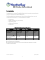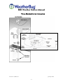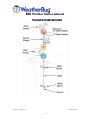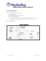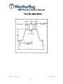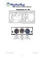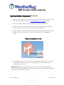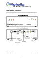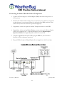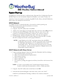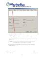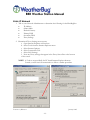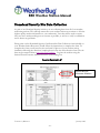
1
BlueBugBox
Weather Station
Installation, Operation, and
Maintenance Manual
January 2004
Version 1.0, Release 1
AWS Part # (7002)
BBB Weather Station Manual
Copyright
Copyright 2005, by AWS Convergence Technologies, Inc.
WeatherBug is a trademark of AWS Convergence Technologies, Inc.
All Rights Reserved.
Information in this document is subject to change without notice and does not represent a
commitment on the part of AWS Convergence Technologies, Inc. The software described in
this document is furnished under a license or non-disclosure agreement. The software may
be used or copied only in accordance with the terms of this agreement. It is against the law
to copy AWS Convergence Technologies, Inc., software onto magnetic tape, disk or any
other medium for any purpose other than for the purchaser's personal use.
Note: This equipment has been tested and found to comply with the limits for a Class A
digital device, pursuant to Part 15 of the FCC rules. These limits are designed to provide
reasonable protection against harmful interference when the equipment is operated in a
commercial environment. This equipment generates, uses and can radiate radio frequency
energy. If not installed and used in accordance with the instruction manual, may cause
harmful interference to radio communications.
For Technical Support relating to this WeatherBug Weather Station
product, call 800-624-4205 or email [email protected].
Version 1.0, Release 1
January 2005
-2-
BBB Weather Station Manual
DISCLAIMER
The procedures, methods and hardware outlined in this manual are intended to provide
general guidelines for installing a WeatherBug Weather Station. Individual sites often have
unique requirements that require materials and specifications that are beyond the scope of
this manual.
All procedures, methods and hardware used to install a WeatherBug Weather Station must
conform to all applicable building codes (local, state and national). Installation
subcontractors are responsible for complying with all applicable codes. Buyer- and/or
installer-provided hardware must be equivalent or better (according to industry standards)
than that specified in the WeatherBug Weather Station installation manual.
The buyer/installer is responsible for any damage caused by installation of the WeatherBug
Weather Station. Furthermore, the buyer/installer is responsible for damage caused as a
result of improper or faulty installation.
THINK SAFETY FIRST! READ THE GETTING STARTED
SECTION OF THIS MANUAL FOR HELPFUL SAFETY TIPS.
Special Note to Buyer/Installer:
Contact WeatherBug Weather Station Technical Support as soon as your WeatherBug
Weather Station installation is complete. WeatherBug must remotely access your weather
station's data to verify proper operation. Call WeatherBug Weather Station Technical
Support even if remote communications are not available at the time of installation.
WeatherBug Weather Station Technical Support:
800-624-4205
[email protected]
Monday - Thursday -- 8:00am-7:00pm EST
Friday -- 8:00am-5:00pm EST
Version 1.0, Release 1
January 2005
-3-
BBB Weather Station Manual
Table of Contents
COPYRIGHT.................................................................................................... 2
DISCLAIMER ................................................................................................... 3
INTRODUCTION............................................................................................. 6
Weather Sensors Specifications........................................................ 6
TYPICAL WEATHER STATION INSTALLATION ............................................... 8
GETTING STARTED ........................................................................................ 9
SAFETY!......................................................................................................... 9
FIRST THINGS ............................................................................................... 10
WEATHER STATION COMPONENTS............................................................. 11
OUTDOOR COMPONENTS ............................................................................... 11
STANDARD OUTDOOR COMPONENTS ..................................................... 12
INDOOR COMPONENTS .................................................................................. 13
INDOOR COMPONENTS ........................................................................ 13
BlueBugBox (BBB) ................................................................................................14
FRONT OF BLUEBUGBOX (BBB) ............................................................ 14
Digital Display (Optional) ......................................................................................15
THE DIGITAL DISPLAY .......................................................................... 15
Computer Connections (Optional)..........................................................................15
Auxiliary Temperature Sensor (Optional) ................................................................15
INSTALLATION............................................................................................. 16
HARDWARE AND TOOL REQUIREMENTS ............................................................. 16
TOOLS REQUIRED .......................................................................................... 17
SITE EVALUATION.......................................................................................... 18
Finding the Best Location ......................................................................................18
SITE SELECTION OPTIONS ..................................................................... 19
INSTALLING OUTDOOR COMPONENTS............................................................... 19
Installation of the Mast..........................................................................................20
TYPICAL BUILDING MOUNT ................................................................... 21
TYPICAL WALL MOUNT BRACKET ........................................................... 22
Securing the Sensors to the Mast ...........................................................................23
Connecting the Weather Sensor Cables..................................................................24
CONNECTING CABLES TO THE TRH........................................................ 25
WIND SENSOR ORIENTATION ................................................................ 26
INSTALLING INDOOR COMPONENTS .................................................................. 28
FRONT OF BLUEBUGBOX ..................................................................... 28
BACK OF BLUEBUGBOX........................................................................ 28
Version 1.0, Release 1
January 2005
-4-
BBB Weather Station Manual
Connecting the Indoor Weather Station Components..............................................29
INDOOR WEATHER STATION CONNECTIONS ............................................ 29
SYSTEM START-UP ....................................................................................... 30
DHCP NETWORK .......................................................................................... 30
DHCP NETWORK WITH PROXY SERVER ............................................................. 30
STATIC IP NETWORK ..................................................................................... 35
SYSTEM OPERATION.................................................................................... 40
NETWORK AND SOFTWARE CONFIGURATIONS .................................................... 40
WeatherBug Camera (Optional)...........................................................................40
HOMELAND SECURITY SITE DATA COLLECTION ........................................ 41
SAMPLE PACKING LIST ......................................................................... 41
CALIBRATION............................................................................................... 42
WEATHERBUG ACHIEVE (FOR SCHOOLS ONLY).......................................... 43
MAINTENANCE ............................................................................................ 44
Version 1.0, Release 1
January 2005
-5-
BBB Weather Station Manual
Introduction
Congratulations on choosing a WeatherBug Weather Station, the premier automated weather
system for educational and commercial applications.
The WeatherBug Weather Station operates 24 hours daily, providing real-time, up-to-thesecond weather observations for 27 real-time parameters, including:
•
•
•
•
•
Temperature
Relative humidity (dew point calculated)
Barometric pressure
Wind speed and direction
Precipitation
Weather Sensors Specifications
Parameter
Wind Speed
Wind Direction *
Temperature
Barometric Pressure ‡
Relative Humidity (RH)
Dew point calculation from
Temp. and RH
Rainfall
*
†
‡
Range
Accuracy
Resolution
0 to 200 mph
0 to 352 deg. †
-30F to +140F
-40F to –30F
-65F to –40F
17.5”Hg to 32.0”Hg
+/- 2 mph
+/- 3 deg.
+/- 1F
+/- 2F
+/- 3F
+/- 0.05”Hg
0.2 mph
0.1 deg.
0.1F
0.1F
0.1F
0.0035”Hg
0 to 100%
+/- 2%
0.1%
Unlimited
+/- 2% @ 1”/hour
.01”
8-degree sector not covered
Wind average covers 0 to 360 degrees
Barometric pressure is measured in inches of mercury (Hg). Metric equivalents are available
through the included software
Version 1.0, Release 1
January 2005
-6-
BBB Weather Station Manual
Introduction (Continued)
Your WeatherBug Weather Station is not difficult to install when all directions are followed
carefully and the installation is well planned prior to assembly. Installation is similar to that
of an outdoor TV antenna (the weather station's outdoor mast and weather sensors) that you
connect to an indoor VCR (the weather station's BlueBugBox unit) and a TV set (the
weather station's optional Digital Display and optional computer). A typical weather station
set-up is shown in Typical Weather Station Installation, page 8.
For Educational Institutions Only
The WeatherBug Network is the largest weather network in the world. More than 7,000
schools across the U. S. operate our easy-to-use WeatherBug Weather Stations to integrate
live, local weather data and technology into classroom learning. This is accomplished
through WeatherBug Achieve (page 43), an online teaching tool that automatically embeds
live weather readings and images from any source on The WeatherBug Network into premade, interactive lessons.
Version 1.0, Release 1
January 2005
-7-
BBB Weather Station Manual
TYPICAL WEATHER STATION INSTALLATION
Version 1.0, Release 1
January 2005
-8-
BBB Weather Station Manual
Getting Started
Safety!
•
While installation of the weather station is not particularly difficult, it does usually
require installation on or near the rooftop, which presents some amount of risk.
•
Installation must conform to national, state and local building code requirements;
adhering to the most stringent guidelines.
•
The weather station should only be installed by qualified individuals who are
comfortable with being on a high ladder or rooftop and who are authorized by the
site administration to perform the installation.
•
To limit risk to self and property, this manual should be thoroughly read and
understood before beginning installation.
•
Stay as far away from other electrical wiring as possible. Never allow the mast, or any
other item, to contact electrical wires or conduit. Injury or death could result.
If desired, WeatherBug can contract the installation of your weather station. For an
installation cost estimate please contact WeatherBug Technical Support at (800) 624-4205
or email [email protected].
Version 1.0, Release 1
January 2005
-9-
BBB Weather Station Manual
Getting Started (Continued)
First Things
1. READ THIS MANUAL THOROUGHLY
It is very important that you read this entire manual prior to installation. If all
instructions are followed carefully, installation of the weather station should be
straightforward and problem free!
2. UNPACK AND INVENTORY WEATHER STATION COMPONENTS
Carefully unpack and check all weather station components using the packing list on
the outside of your shipping container. Report any damaged or missing components
to WeatherBug Technical Support immediately.
3. BEGIN INSTALLATION
4. COMPLETE AND RETURN THE HOMELAND SECURITY SITE DATA
PACKET TO WEATHERBUG TECHNICAL SUPPORT
After completing installation, please complete and return the Homeland Security Site
Data Packet as soon as possible.
Version 1.0, Release 1
January 2005
- 10 -
BBB Weather Station Manual
Weather Station Components
Outdoor Components
The outdoor components (see Standard Outdoor Components, on page 12) of a standard
WeatherBug Weather Station are:
• Sensor Shelter (with remote Temperature/Relative Humidity (TRH) Sensor mounted
inside)
• Wind Sensor
• Rain Gauge
• Data Cable
The Weather Station's sensor suite uses accurate and rugged sensors. The wind speed and
direction sensor is an R.M. Young wind sensor, widely acknowledged to be one of the top
Wind Sensors available. The Rain Gauge is a standard tipping bucket that measures .01
inches of rain per tip.
The remote Temperature/Relative Humidity (TRH) Sensor is a metal box about the size of a
deck of cards that is mounted inside the Sensor Shelter. The circuit board within the TRH
serves as an analog-to-digital (A-D) converter. Digital conversion provides a high degree of
accuracy and flexibility for distributing your weather station data.
The Sensor Shelter (often referred to as a convection-aspirated shelter) serves two primary
purposes:
• It shields the remote TRH sensor from direct sunlight, which could yield inaccurate
readings (the design minimizes heat build-up by enabling natural air currents to flow
through it, resulting in "true" air temperature readings).
• Second, it protects the remote TRH sensor from rain, ice and snow, which could
also produce inaccurate readings as well as cause damage to the relative humidity
sensor.
The Data Cable transports data from the weather station's outdoor components to the
BlueBugBox (BBB), located indoors. The Data Cable is UV-rated and can be run along the
weather station mast without conduit; however, conduit should be used to protect the cable
when running it over the length of roof and into the building. If your building codes require
different ratings of cable, please contact WeatherBug Weather Station Technical Support.
NOTE: Cable should not be run across rooftop surfaces without protective conduit
(not included).
Version 1.0, Release 1
January 2005
- 11 -
BBB Weather Station Manual
STANDARD OUTDOOR COMPONENTS
Version 1.0, Release 1
January 2005
- 12 -
BBB Weather Station Manual
Indoor Components
The weather station indoor components are:
• BlueBugBox (BBB)
• Optional Auxiliary Temperature Sensor
• Optional Digital Display(s)
• WeatherBug Achieve * (Web-based teaching application that includes interactive
lesson plans, graphing, mapping, live weather data display and more)
* FOR SCHOOLS ONLY
INDOOR COMPONENTS
Version 1.0, Release 1
January 2005
- 13 -
BBB Weather Station Manual
Indoor Components (Continued)
BlueBugBox (BBB)
The BlueBugBox (BBB) is a microprocessor-controlled computer with battery backup that
uses your existing high-speed internet connection to transmit weather data out to the
WeatherBug network. It receives live input from the remote TRH sensor, processes and
stores the data in its non-volatile electronic memory, and distributes it. The BlueBugBox also
houses the barometric pressure, indoor temperature, and optional Auxiliary Temperature
Sensor.
The signals from the remote TRH sensor come through the main Data Cable into the
BlueBugBox. It is essential that there are no sharp bends or crimps in the cable. The cable
should be protected (stabilized) where it passes through the exterior wall.
The BlueBugBox has two additional outputs to the optional Digital Display and an optional
computer.
FRONT OF BLUEBUGBOX (BBB)
The BlueBugBox stores data at a default rate of once per hour. This rate may be re-set to
intervals of between one minute and up to one hour. Up to four months of data at the onehour interval is stored in the BBB.
The BlueBugBox's internal battery backup prevents data loss during power outages for up to
12 hours. The BBB is designed to continue transmitting weather data during power outages
as long as the network is powered. Once power is restored, the battery automatically
recharges and the BBB will automatically resume sending current and historical data.
Version 1.0, Release 1
January 2005
- 14 -
BBB Weather Station Manual
Indoor Components (Continued)
Digital Display (Optional)
The optional Digital Display receives live data every second from the BBB and displays it on
several large digital LEDs. Housed in an attractive oak case, the display shows daily highs,
lows and rates of change. For more information, see the Digital Display User's Manual
(also provided on your Resource CD).
THE DIGITAL DISPLAY
Computer Connections (Optional)
The BBB can also be connected to a PC through a serial cable.
Auxiliary Temperature Sensor (Optional)
The BBB can also be connected to an Auxiliary Temperature Sensor, which looks like a wire
and can be run to measure temperature in aquariums, terrariums, or other areas.
Version 1.0, Release 1
January 2005
- 15 -
BBB Weather Station Manual
Installation
Hardware and Tool Requirements
The following hardware (equivalent or better quality) is required to install the WeatherBug
Weather Station. If you are using a WeatherBug contracted installer, they will provide these
materials.
Required Parts Not Included
•
•
•
•
•
•
•
•
•
Mounting hardware (heavy-duty wall mounting brackets)
Grounding cable and appropriate connectors
Silicone caulk (to seal conduit and cable entry points into building)
Mast
o Galvanized Rigid Conduit (GRC) approximately 1/8 inch thickness
(painted optional)
o 1 ¼ inch maximum outside diameter (at top of mast)
o Mast can be comprised of two sections that total a minimum of 15 feet when
assembled. A two-section mast is recommended so the top section can be
raised/lowered for easier installation and maintenance of the weather
sensors. The bottom section should remain securely fastened.
o (3) ¼-20x2” grade 8 bolts with accompanying flat washer, lock washer, and
nuts
Mounting hardware (heavy-duty wall mounting brackets)
Conduit for exterior data cable
o Select conduit type based on your local building codes
o 1 ¾ inch outside diameter for weather station data (and camera) cable
Silicone caulk (to seal conduit and cable entry point into building)
Grounding rod, if necessary
Guy wire, if necessary to prevent top of mast from shaking
For your convenience, specifications on the parts and tools you will need can be found at:
http://download.aws.com/manuals/partsrequired.pdf
Version 1.0, Release 1
January 2005
- 16 -
BBB Weather Station Manual
Tools Required
The following is a list of tools necessary to install the outdoor WeatherBug Weather Station
and route the data cables into the building (actual tool requirements may vary depending on
site configuration):
1.
2.
3.
4.
5.
6.
7.
Compass
Step ladder (6-8 feet)
Level
Electric drill and masonry drill bits
Flathead and Phillips screwdrivers
Adjustable wrench
Wrenches
• 7/16 inch for Sensor Shelter nuts
• 3/8 inch for mast mounting brackets
• 1/2 inch for mast mounting brackets
• 9/16 inch for mast mounting brackets
• 5/8 inch for mast mounting brackets
8. Pliers
9. Socket set (optional)
10. Wire cutters for cable ties
Version 1.0, Release 1
January 2005
- 17 -
BBB Weather Station Manual
Site Evaluation
Before installing your weather station, conduct a thorough site evaluation to identify the best
location for each component, including the outdoor sensors, and BlueBugBox. This requires
working with someone who has access to all grounds, including the roof.
The importance of this step cannot be overemphasized! A well-planned installation
eliminates almost all problems that could be encountered later. It may prevent
having to move part or all of the station.
The placement of each component is dependent, to some extent, on the placement of the
other components. All sites have restrictions. Care must be taken to select the best location
for each component. The accuracy of weather readings can depend on the weather station's
location. This section provides information to help you select the best location possible.
Finding the Best Location
Locate your outdoor WeatherBug Weather Station in a location that takes all of the
following into account:
o In an open area
o Clear of wind obstructions (especially for the prevailing wind direction)
o Wind sensor must be a minimum of 10 feet from roof
o Sensor shelter must be a minimum of 8 feet from roof
o Far away from ventilation and heat sources (minimum of 50 feet)
o Safe from vandalism
o Away from large, asphalt parking lots
o Close enough for cables to connect to indoor equipment (cables are minimum of 200
feet – additional lengths may be purchased in 100-foot sections)
See Site Selection Options on page 19 for an overhead layout of a typical installation for the
outdoor components.
Locate your indoor WeatherBug equipment in a location that takes all of the following into
account:
o Staffed location to ensure equipment is operating year-round
o Year-round power and internet connection
o Close to computer and phone for technical support
o A secure area where equipment will not be tampered with or turned off
o Adequate ventilation (equipment must not get over-heated)
Version 1.0, Release 1
January 2005
- 18 -
BBB Weather Station Manual
SITE SELECTION OPTIONS
Locating Your Outdoor WeatherNet Weather Station Components
Grassy Expanse
Main Roof
(1 Story)
N
1
Gymnasium
Roof
(2Stories)
Prevailing Winds
(Westerly in Much
of U.S.)
2
Parking Lot
Example Case:
In the example above, Site 1 would be the preferred location for the mast and sensors. Site 1 has clear
exposure to the prevailing winds and offers unobstructed wind measurement. Although Site 2 may
offer a good location for prevailing winds, the gymnasium roof would cause wind obstructions and the
proximity to the parking lot could impact temperature readings. Wind measurements should be given
precedence when selecting an install location.
Installing Outdoor Components
Installing outdoor weather station components is similar to installing an outdoor TV
antenna. There are three basic steps after ensuring the selected location fulfills site criteria
(see Site Evaluation, page 18):
1. Installation of the Mast
2. Securing the Sensors to the Mast
3. Connecting the Weather Sensor Cables and Grounding
Data cables are not rated for movement below +15ºF. Do NOT install the weather station if
the outdoor temperature is less than 15º F.
Version 1.0, Release 1
January 2005
- 19 -
BBB Weather Station Manual
Installation of the Mast
IMPORTANT: Ensure that all mounting brackets and mast components meet the local
building codes and work with the installation site you have chosen.
Properly securing the mounting brackets and mast is critical for a successful installation.
The mounts must withstand harsh environments, including high winds. When determining
the appropriate mounting brackets for your installation, consider the following:
•
Building material to which you will be mounting the mast (e.g., brick, block, siding,
etc.)
•
Roof overhang (mounting brackets must be placed so that the mast clears the roof)
Secure the brackets to the building as shown in Typical Building Mount, page 21. Install the
bottom mounting bracket in vertical alignment with the top bracket. The mast must be
completely vertical. Ensuring vertical alignment is critical for accurate sensor measurements
once the installation is complete and the station is up and running.
Version 1.0, Release 1
January 2005
- 20 -
BBB Weather Station Manual
TYPICAL BUILDING MOUNT
4’ Minimum
between Brackets
6″ From Bottom
of Mast
It is recommended that you use a heavy-duty mounting bracket similar to that shown in
Typical Wall Mount Bracket, page 22. Brick walls require anchors in addition to the lag
screws. Block or thin wall siding may require a toggle. Your installer is responsible for
selecting the appropriate industry standard or better mounting hardware, which should be
available in any local hardware or electrical supply store.
Version 1.0, Release 1
January 2005
- 21 -
BBB Weather Station Manual
TYPICAL WALL MOUNT BRACKET
Version 1.0, Release 1
January 2005
- 22 -
BBB Weather Station Manual
Installing Outdoor Components (Continued)
Follow these steps to secure the mast to the wall mounting brackets:
1. Loosen the bolts on the outside of the wall mounting brackets so the larger diameter
mast can be inserted into the slots on the brackets (do not loosen the screws that
hold the brackets to the wall).
2. Insert the mast into and through both wall mounting bracket slots and tool tighten
bolts.
3. If using a 2-piece mast per the recommendations in the Parts Required document
(http://download.aws.com/manuals/PartsRequired.pdf), insert a Safety Bolt into
the bottom of the mounted mast. This bolt will prevent the top portion of the mast
from sliding though and falling to the ground during installation.
Refer to the Quick Install Guide poster for additional installation
illustrations.
Securing the Sensors to the Mast
Follow these steps to secure the sensors to the mast so that the sensors are oriented properly
and so that they meet the minimum required height above the roof surface (refer to Standard
Outdoor Components, page 12):
1. If your mast is in more than one section, mount the sensors on the top section. The
sections can be joined after securing the sensors and making the appropriate
connections.
2. Tilt the mast so that the sensor U-bolts can slide down over the top.
3. Mount the Rain Gauge by sliding its U-bolt down the mast until it is low enough to
be easily accessible for periodic cleanings. Finger-tighten the U-bolt but leave its
cable loose for now.
4. Mount the Sensor Shelter by sliding its U-bolt down the mast until it is two feet
below the top. It should be 180◦ opposite the Rain Gauge so that it does not block
the rain when raised. Finger-tighten the U-bolt making sure the shelter is upright so
that rain and snow cannot fall inside. Do not connect cables yet.
Version 1.0, Release 1
January 2005
- 23 -
BBB Weather Station Manual
Installing Outdoor Components (Continued)
5. Carefully remove the Wind Sensor from its box (its cable is already attached) and
place it on the top of the mast so that the black junction box will face SOUTH when
the mast is raised. Securely tighten pipe clamp. Do not secure or connect the Wind
Sensor cable at this point.
6. Adjust the sensor shelter to ensure it is a minimum of 8 feet from the roof’s surface
and is rotated so that it hangs over the ground or lowest roof. After ensuring proper
alignment of equipment, tool tighten Sensor Shelter and Rain Gauge U-bolts.
Connecting the Weather Sensor Cables
Follow the steps below to connect the sensor cables to the remote Temperature/Relative
Humidity (TRH) sensor (inside Sensor Shelter) and to connect the Data Cable from the
TRH to the BlueBugBox (BBB) (see the illustration Connecting Cables to the TRH, page25):
IMPORTANT: Do not damage or strain cables or connectors. One loose cable
connection can cause system errors.
1. Remove the 200' Data Cable from the shipping box and remove wire ties. This is the
cable that connects the outdoor TRH to the indoor BBB. Note INDOOR and
OUTDOOR labels on either end of the cable.
2. Loosen the mounting (“thumb”) nuts and open bottom plate of Sensor Shelter.
3. Route the Data Cable labeled "OUTDOOR" through the side opening of the
bottom plate and connect to the DATA connector at the left on the TRH. Insert
the cable into the socket. Rotate the connector clockwise to lock it. (DATA
connector has a white washer that matches the white band of the Data Cable.)
4. Route the wind cable down the mast until it is beneath the Sensor Shelter, through
the opening in the bottom plate and connect the yellow end of the wind cable to the
WIND connector in the center on the TRH. (The WIND connector has a yellow
washer that matches the yellow band of the wind cable.)
5. Route the Rain Gauge cable up the mast until it is beneath the Sensor Shelter,
through the opening in the bottom plate and connect the blue end of the Rain
Gauge cable to the RAIN connector at the right on the TRH. (The RAIN connector
has a blue washer that matches the blue band of the Rain Gauge cable.)
6. Replace the bottom plate and tighten mounting (“thumb” nuts).
Version 1.0, Release 1
January 2005
- 24 -
BBB Weather Station Manual
CONNECTING CABLES TO THE TRH
Version 1.0, Release 1
January 2005
- 25 -
BBB Weather Station Manual
Installing Outdoor Components (Continued)
7. Secure the three cables below the Sensor Shelter connectors with a cable tie. Form a
drip loop with the three cables (see Connecting Cables to the TRH, page25).
8. Secure the WIND, RAIN and DATA cables to the mast with cable ties.
9. Raise top section of mast and secure in place by inserting bolt(s) through aligned
holes in top and bottom section of mast. Tool-tighten the bolts.
10. Using a compass, confirm that the Wind Sensor’s black junction box is still pointing
South. If necessary, lower mast and rotate Wind Sensor so it faces South (see
below).
WIND SENSOR ORIENTATION
11. The 200' Data Cable is now ready to be routed inside the building. Plan your cable
route carefully. Make sure you know exactly where your cables will be before
committing to your route.
IMPORTANT: When routing cables and connectors, be careful not to damage or
strain them. Run the Data Cable in conduit across the length of the building and around
sharp corners (conduit not included).
Version 1.0, Release 1
January 2005
- 26 -
BBB Weather Station Manual
Installing Outdoor Components (Continued)
NOTES:
•
WeatherBug recommends that you tape the connector ends together before
running them inside the building (tape them fully to prevent damage or loosening
individual wires). Do not cut connectors off. A single loose cable connection
can cause system errors.
•
Route Data Cable through 1¾ inch outside diameter conduit on exterior of
building.
•
Seal building hole and both ends of conduit using caulk/putty.
•
Because the WeatherBug Weather Station Data Cable is UV-rated, conduit is not
required along the length of the mast, but should be used along the length of the
building.
•
Use the shortest route possible when running cables inside the building.
•
The Data Cable ends at the BBB. Excess cable should be coiled, tied and stored
near the BBB.
12. Securely attach a grounding cable to a metal part of the mast. The mast MUST be
grounded to protect against lightning and static charge build-up. The ground wire
must be connected to an appropriate location (consult a school or district electrician
to ensure proper grounding).
IMPORTANT: Ground cable and installation must conform to all applicable local
building codes. The mast must be grounded to an "earth" ground.
The buyer/installer is responsible for this procedure and for ensuring that materials and
methods conform to all applicable building codes.
Version 1.0, Release 1
January 2005
- 27 -
BBB Weather Station Manual
Installing Indoor Components
The final step is the installation of all indoor components, including the BBB and optional
Digital Display.
FRONT OF BLUEBUGBOX
BACK OF BLUEBUGBOX
Version 1.0, Release 1
January 2005
- 28 -
BBB Weather Station Manual
Connecting the Indoor Weather Station Components
1. Connect the Power Supply to the BlueBugBox (BBB) and ensure that power is in
OFF position.
2. Find the end of Data Cable coming from your outdoor sensors. Place the connector
so that the arrow is on top and connect it to the back of the BBB, under the "Data
Cable" label (be sure the connector is positioned properly).
3. If applicable, connect the optional Auxiliary Temperature Sensor to the BBB.
4. If applicable, for the optional Digital Display, connect other end of 25-foot Display
Cable cord (“telephone line”) to the Digital Display (See the Digital Display
Operations Manual for Digital Display installation instructions).
5. Using the supplied Ethernet LAN Cable, plug the BBB into your Local Area
Network (LAN) or Internet Connection.
6. Plug the BBB and optional Digital Display Power Supplies into the Power Strip.
INDOOR WEATHER STATION CONNECTIONS
Version 1.0, Release 1
January 2005
- 29 -
BBB Weather Station Manual
System Start-up
Assuming that your site network is configured with a Dynamic Host Configuration Protocol
(DHCP) where you are automatically assigned an IP address, your station is ready to be
turned on. If your site network is currently using DHCP with a Proxy or Static IP addresses,
please refer to the appropriate section below.
DHCP Network
Your BBB should be connected and ready to be turned on (before powering any
component, check to ensure that all connections are correct).
1. Turn on the Power Strip.
2. Using the “On/Off” switch, turn on the BBB.
3. A flash of all 4 status lights on the right hand side of the front of the BBB will occur.
4. Verify that the Green LED lights on the back of the box, next to the “LAN”
connection, are illuminated or flashing to indicate a live internet connection.
5. During the next 5 minutes the lights A, B, and C will come on in sequence.
6. Call WeatherBug Weather Station Technical Support at 800-624-4205 to confirm
that data is being received and to ensure proper calibration.
NOTE: A rapid flashing of the ABC status lights indicates that the BBB is
downloading a new program. Once the program has been downloaded
the ABC lights will turn green for a second and then the box will
automatically reboot. The download and rebooting process could take
up to 10 minutes. Upon successful completion of upgrade the box will
automatically resume sending data.
DHCP Network with Proxy Server
1. Using an existing computer on the site’s network to Determine the Proxy Settings:
a. Open Internet Explorer web browser.
b. Select Tools from the Internet Explorer menu.
c. Select Internet Options.
d. Select Connections Tab.
e. Select LAN Settings.
f. Note the Proxy settings that appear in the Proxy Server Box at the bottom of the
screen.
NOTE: A-F above are specifically for PC based Internet Explorer browser.
Consult your browser’s documentation to follow a similar procedure.
2. Using the “On/Off” switch, turn on the Power to the BBB.
3. Verify that the Green LED lights on the back of box, next to the “LAN”
connection, are illuminated or flashing to indicate a live internet connection.
Version 1.0, Release 1
January 2005
- 30 -
BBB Weather Station Manual
4. Allow five minutes for BBB to boot up and for the C LED to illuminate.
NOTE: During this time the Green A, B, and C LEDs on the front of the box
may turn on/off, flash, etc.
5. Using another PC computer on the network (same subnet), download the latest
BugBox Network Config program from http://wxsinfo.aws.com/TINI/Config.html
and save it to the computer desktop.
NOTE: If your current network setting does not allow downloads of .EXE files
please download either the .ZIP file or the .EX file. If the .EX file is
downloaded, rename the file extension to .EXE before starting/opening
the file.
6. Double click on the BugBoxCfg program.
NOTE: To use the BugBox Network Config program the C Light on the front of
the BBB must be illuminated.
Version 1.0, Release 1
January 2005
- 31 -
BBB Weather Station Manual
7. Using the BugBox Network Config program, select Search to seek out all BugBoxes
on the network.
NOTE: If the BugBox Network Config program was unable to find your BBB
select the Options button, change the number of seconds from 10 to 50,
and select OK. Select Search again from the BugBox Network Config
program.
Version 1.0, Release 1
January 2005
- 32 -
BBB Weather Station Manual
8. Select the MAC address for the BBB.
NOTE: If DHCP is enabled on your network, the BBB may appear with another
IP address.
9. Using the IP address box in the center of the screen, type 0 between each dot in the
IP address field.
NOTE: Entering all 0’s for the IP address prevents accidentally setting the
current DHCP IP as a static IP address for your BBB.
10. Using the boxes on the right side of the screen, type in the Proxy information
obtained in Step 1.
Version 1.0, Release 1
January 2005
- 33 -
BBB Weather Station Manual
11. If your proxy requires a login, enter the User name and Password in the appropriate
boxes.
NOTE: The User name and Password fields are limited to 32 characters per field.
If no Username and Password are required leave fields blank.
12. Select the Set button from the lower right hand portion of the BugBox Network
Config program.
NOTE: After the Set button is selected the box will automatically restart and will
take a few minutes to reappear on the network.
13. After approximately five minutes, the A, B, and C LEDs should be green (no
flashing).
14. Call WeatherBug Weather Station Technical Support at 800-624-4205 to confirm
that data is being received and to ensure proper calibration.
Version 1.0, Release 1
January 2005
- 34 -
BBB Weather Station Manual
Static IP Network
1. Talk to your Network Administrator to determine the following for the BlueBugBox:
•
IP Address
•
Subnet Mask
•
Default Gateway
•
Primary DNS
•
Secondary DNS
•
Proxy Settings
2. Determine if Proxy Settings are necessary:
a. Open Internet Explorer web browser.
b. Select Tools from the Internet Explorer menu.
c. Select Internet Options.
d. Select Connections Tab.
e. Select LAN Settings.
f. Note any Proxy settings that appear in the Proxy Server Box at the bottom
of the screen.
NOTE: A-F above are specifically for PC based Internet Explorer browser.
Consult your browser’s documentation to follow a similar procedure.
Version 1.0, Release 1
January 2005
- 35 -
BBB Weather Station Manual
3. Using the “On/Off” switch, turn on the Power to the BBB.
4. Verify that the Green LED lights on the back of the box, next to the “LAN”
connection, are illuminated or flashing to indicate a live internet connection.
5. Allow five minutes for BBB to boot up and for the C LED to illuminate.
NOTE: During this time the Green A, B, and C LEDs on the front of the box
may turn on/off, flash, etc.
6. Using another PC computer on the network (same subnet), download the latest
BugBox Network Config program from http://wxsinfo.aws.com/TINI/Config.html
and save it to the computer desktop.
NOTE: If your current network setting does not allow downloads of .EXE files
please download either the .ZIP file or the .EX file. If the .EX file is
downloaded, rename the file extension to .EXE before starting/opening
the file.
7. Double click on the BugBoxCfg program.
Version 1.0, Release 1
January 2005
- 36 -
BBB Weather Station Manual
NOTE: To use the BugBox Network Config program the C Light on the front of
the BBB must be illuminated.
8. Using the BugBox Network Config program, select Search to seek out all BugBoxes
on the network.
NOTE: If the BugBox Network Config program was unable to find your BBB
select the Options button, change the number of seconds from 10 to 50,
and select OK. Select Search again from the BugBox Network Config
program.
Version 1.0, Release 1
January 2005
- 37 -
BBB Weather Station Manual
9. Select the MAC address for the BBB with the IP address of 192.168.237.227 (the
default IP address for the BBB).
NOTE: If DHCP is enabled on your network, the BBB may appear with another
IP address.
10. Using the boxes at the bottom of the screen, type in the following obtained in Steps
1 and 2:
• IP Address
• Mask
• Gateway
• Primary DNS
• Secondary DNS
• Proxy (if applicable)
• Proxy User name (if applicable) – NOTE: Limit of 32 characters
• Proxy Password (if applicable) – NOTE: Limit of 32 characters
Version 1.0, Release 1
January 2005
- 38 -
BBB Weather Station Manual
11. Select the Set button from the lower right hand portion of the BugBox Network
Config program.
NOTE: After the Set button is selected the box will automatically restart and will
take a moment to reappear on the network.
12. After a few minutes, the A, B, and C LEDs should be green (no flashing).
13. Call WeatherBug Weather Station Technical Support at 800-624-4205 to confirm
that data is being received and to ensure proper calibration.
Version 1.0, Release 1
January 2005
- 39 -
BBB Weather Station Manual
System Operation
Under normal conditions, your WeatherBug Weather Station should never be turned off. It
is designed to operate 24 hours daily, every day, without operator input or assistance.
If applicable, your optional Digital Display should immediately indicate current weather
conditions, although the time may need to be set and the barometric pressure calibrated;
WeatherBug does this calibration remotely upon your activation call.
The optional Digital Display(s) should continuously indicate current weather conditions. If
transmission between the remote weather module and BBB is interrupted for more than one
minute, the temperature values on the display will default to a -100°F (± 4°F) error code.
Network and Software Configurations
The BlueBugBox (BBB) requires that the Port 80 (http) and Port 9500 UDP outbound must
be open for live weather data to transmit to the WeatherBug network.
FIREWALL: Your Network Administrator must be contacted to make changes in the
firewall. If you have any difficulty understanding information concerning Internet
requirements, please pass all of this information along to your Network Administrator. This
person will know what to do and is also welcome to contact WeatherBug Technical Support
directly if there are questions.
WeatherBug Camera (Optional)
WeatherBug camera software uses Port 21 outbound for FTP to send images to our servers.
Every 5 minutes, the WeatherBug camera software FTP’s an image to
http://send.instacam.com. A key number is provided that will differentiate your image from
other cameras on the network. Both active and passive FTP can be used to send the images.
This software is pre-installed on the computer and may also be downloaded.
CAMERA OWNERS: The WeatherBug Weather Station Installation, Operation, and
Maintenance Manual does not address the installation of WeatherBug cameras. The additional
steps required for camera installation are covered in the manuals on the Resource CD. If you
have a camera, please read through the camera manual in addition to the WeatherBug Weather
Station Installation, Operation, and Maintenance Manual before beginning installation of the
weather station.
Version 1.0, Release 1
January 2005
- 40 -
BBB Weather Station Manual
Homeland Security Site Data Collection
As part of our Homeland Security initiative, we are collecting data from all of our weather
monitoring stations. This will help ensure that your weather station can continue to offer the
highest quality weather information to your community. Your data will be used to ensure
that your site's weather readings are as accurate as possible, as well as to verify its calibration
and to detect any problems.
Please print out the Homeland Security Certification Site Data Collection form included on
your Weather Station Resource CD and follow the instructions to complete the form. To
complete the form you will need to take and email 12 photos of your weather station
installation following the directions/sample photos in the site data collection form. The site
data can be entered online at www.aws.com/sitedata/. Log into the website using the
Station ID and Customer Number found on your Packing List.
SAMPLE PACKING LIST
Station ID and
Customer Number
Version 1.0, Release 1
January 2005
- 41 -
BBB Weather Station Manual
Calibration
If your WeatherBug Weather Station is properly installed, only the time and barometric
pressure will need to be calibrated. The barometric pressure sensor must be adjusted to
compensate for altitude differences between the WeatherBug weather station
production/testing location and your installation site. The weather station time is typically
pre-set to US Eastern Standard Time (EST). All other calibration is performed prior to
shipment.
The WeatherBug Weather Station is designed for remote calibration by WeatherBug via the
Internet. You must properly configure your weather station for remote access to enable
remote calibration by WeatherBug Technical Support.
Part of the equation for barometric pressure is elevation. WeatherBug has already entered
your general elevation. If possible, please provide your exact Latitude/Longitude/Elevation
if you have this information available via a GPS system. If not, please confirm the address
for the installation location so that an exact Latitude/Longitude/Elevation can be entered to
ensure your site plots properly in the WeatherBug products.
WeatherBug Technical Support:
800-624-4205
[email protected]
Monday - Thursday -- 8:00am-7:00pm EST
Friday -- 8:00am-5:00pm EST
Version 1.0, Release 1
January 2005
- 42 -
BBB Weather Station Manual
WeatherBug Achieve (for Schools Only)
WeatherBug's award-winning educational software and curriculum is now an integrated
Web-based application, called WeatherBug Achieve. It features ready-to-use interactive
lesson plans, graphing, mapping, live display, historical data and more. This state-of-the-art
educational tool is designed by meteorologists, teachers, and students to make teaching and
learning easier, more interactive and fun.
Using WeatherBug Achieve, your students can perform activities like calculate mean, median
and mode using live weather data. Real-time weather information from your school's
WeatherBug Weather Station, or any of more than 7,000 schools in the WeatherBug
program, can be automatically embedded into your lesson plans. You and your students will
enjoy the K-12 lesson plans, which align with National and State Standards in math, science,
and geography.
Version 1.0, Release 1
January 2005
- 43 -
BBB Weather Station Manual
Maintenance
Under normal conditions, your WeatherBug Weather Station will require very little
maintenance. Most maintenance issues can be evaluated and diagnosed remotely by
WeatherBug Quality Control. All components are “Plug-and-Play” (defective sensors can be
removed simply by disconnecting them from the cable connections).
Check the Rain Gauge every three months or any time that readings appear to be lower than
they should be. Clear any debris clogging the inlet into the tipping bucket.
Looking down into the top of the Rain Gauge you will see that it is cup-shaped and, at the
bottom of the cup, there is a small hole. This hole must be totally clear for the gauge to be
able to measure rainfall accurately. Bamboo skewers or a similar instrument are excellent for
this task.
Version 1.0, Release 1
January 2005
- 44 -