1
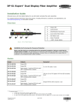
DF-G1 Expert™ Dual Display Fiber
Amplifier
Instruction Manual
Original Instructions
161999 Rev. E
1 April 2014
161999
DF-G1 Expert™ Dual Display Fiber Amplifier
Contents
1 Product Description
....................................................................................................... 3
1.1 Models
....................................................................................................................................3
1.2 Overview
................................................................................................................................ 4
1.3 Top Panel Interface
.................................................................................................................. 4
2 Installation Instructions
................................................................................................ 6
2.1
2.2
2.3
2.4
Mounting Instructions
............................................................................................................... 6
Installing the Fibers
..................................................................................................................6
Fiber Adapters
......................................................................................................................... 6
Wiring Diagrams
...................................................................................................................... 7
4.1
4.2
4.3
4.4
4.5
4.6
4.7
4.8
TEACH Selection
.....................................................................................................................10
Response Speed
.....................................................................................................................10
Offset Percent
........................................................................................................................10
Auto Thresholds
..................................................................................................................... 10
Delays/Timers
........................................................................................................................11
Display Readout
..................................................................................................................... 11
Gain Selection
........................................................................................................................11
Factory Defaults
.....................................................................................................................11
6.1
6.2
6.3
6.4
6.5
6.6
6.7
Two-Point TEACH
.................................................................................................................... 13
Dynamic TEACH
...................................................................................................................... 15
Window SET
........................................................................................................................... 17
Light SET
............................................................................................................................... 18
Dark SET
...............................................................................................................................20
Calibration SET
....................................................................................................................... 22
Troubleshooting
..................................................................................................................... 24
6.7.1 Manual Adjustments Disabled
......................................................................................... 24
6.7.2 Percent Minimum Difference after TEACH
......................................................................... 24
6.7.3 Percent Offset after SET
................................................................................................ 24
6.7.4 Threshold Alert or Threshold Error
...................................................................................24
3 Run Mode
.......................................................................................................................8
4 Program Mode
............................................................................................................... 9
5 Remote Input (not available on IO-Link models)
.......................................................... 12
6 Adjust Mode
.................................................................................................................13
7 IO-Link Interface
.......................................................................................................... 25
8 Specifications
.............................................................................................................. 26
8.1 Excess Gain Curves
................................................................................................................ 27
8.2 Beam Patterns
........................................................................................................................ 29
8.3 Dimensions
............................................................................................................................ 31
9 Accessories
.................................................................................................................. 32
9.1 Quick-Disconnect Cordsets
...................................................................................................... 32
10 Banner Engineering Corp Limited Warranty
............................................................... 34
DF-G1 Expert™ Dual Display Fiber Amplifier
1 Product Description
Advanced sensor with dual digital displays for use with plastic and glass fiber optic assemblies
•
•
•
•
•
•
•
•
•
•
•
Easy to read dual digital displays show both signal level and threshold
simultaneously
Lever action fiber clamp provides stable, reliable, and trouble-free fiber
clamping
Simple user interface ensures easy sensor set-up and programming via
displays and switches/buttons, remote input teach wire, or IO-Link
Expert TEACH and SET methods ensure optimal gain and threshold for all
applications, especially low contrast applications
User has full control over all operating parameters: threshold, Light
Operate or Dark Operate, output timing functions, gain level, and response
speed
Thermally stable electronics minimize warm-up drift and the effect of sideby-side mounting of multiple fiber amplifiers
ECO (economy) display mode reduces amplifier power consumption by
25%
Cross talk avoidance algorithm allows two sensors to operate in close
proximity for many applications
Response speeds of: 200 µs (High Speed), 500 µs (Standard), 2 ms (Long
Range), and 5 ms (Extra Long Range) allow the operator to optimize for
fast or long distance applications
Sleek 10 mm wide housing mounts to 35 mm DIN rail
Visible red LED sensing beam
WARNING: Not To Be Used for Personnel Protection
Never use this device as a sensing device for personnel protection. Doing so could lead to
serious injury or death. This device does not include the self-checking redundant circuitry necessary
to allow its use in personnel safety applications. A sensor failure or malfunction can cause either an
energized or de-energized sensor output condition.
1.1 Models
Connector1
Model
Outputs
DF-G1-NS-2M
Single NPN
DF-G1-PS-2M
Single PNP
DF-G1-KS-2M
Dual outputs, 1 push-pull IO-Link and 1
PNP (complementary outputs)
DF-G1-NS-Q5
Single NPN
DF-G1-PS-Q5
Single PNP
DF-G1-KS-Q5
Dual outputs, 1 push-pull IO-Link and 1
PNP (complementary outputs)
DF-G1-NS-Q7
Single NPN
DF-G1-PS-Q7
Single PNP
DF-G1-KS-Q7
Dual outputs, 1 push-pull IO-Link and 1
PNP (complementary outputs)
2 m (6.5 ft) cable, 4-wire
150 mm (6 in) PVC pigtail, M12 Euro QD connector,
4-pin
Integral M8 Pico QD connector, 4-pin
1 Connector options:
•
•
•
A model with a QD connector requires a mating cordset (see Quick-Disconnect Cordsets on page 32).
For 9 m cable, change the suffix 2M to 9M in the 2 m model number (example, DF-G1-NS-9M).
For 150 mm (6 in) PVC pigtail, M8 Pico QD connector, 4-pin change the suffix 2M to Q3 in the 2 m model number (example,
DF-G1-NS-Q3).
3
DF-G1 Expert™ Dual Display Fiber Amplifier
1.2 Overview
The DF-G1 is an easy-to-use, DIN-rail-mountable fiber optic sensor. It provides high-performance sensing in low-contrast
applications.
The sensor’s compact housing has dual digital displays (Red/Green) and a bright output LED for easy programming and
status monitoring during operation. The sensor features a single discrete output, either NPN or PNP, by model.
The DF-G1 features increased temperature compensation compared with previous fiber optic sensors. An accessory clamp
is available to secure a bank of connected sensors together on a DIN rail (see Accessories on page 32).
1
Output LED
2
LO/DO Switch
3
RUN/PRG/ADJ Mode Switch
4
Lever Action Fiber Clamp
5
Red Signal Level
6
Green Threshold
7
+/SET/- Rocker Button
Figure 1. DF-G1 Model Features
1.3 Top Panel Interface
Opening the dust cover provides access to the top panel interface. The top panel interface consists of the RUN/PRG/ADJ
mode switch, LO/DO switch, +/SET/- rocker button, dual red/green digital displays, and output LED.
RUN/PRG/ADJ Mode Switch
The RUN/PRG/ADJ mode switch puts the sensor in RUN, PRG (Program), or ADJ (Adjust) mode. RUN mode
allows the sensor to operate normally and prevents unintentional programming changes via the +/SET/button. PRG mode allows the sensor to be programmed through the display driven programming menu (see
Program Mode on page 9 ). ADJ mode allows the user to perform Expert TEACH/SET methods and
Manual Adjust (see Adjust Mode on page 13 ).
LO/DO Switch
The LO/DO switch is used to select Light Operate or Dark Operate mode. In Light Operate mode, the output
is ON when the sensing condition is above the threshold (for Window SET, the output is ON when the
sensing condition is inside the window). In Dark Operate mode, the output is ON when the sensing condition
is below the threshold (for Window SET, the output is ON when the sensing condition is outside the
window).
+/SET/- Rocker Button
The +/SET/- rocker button is a 3-way button. The +/- positions are engaged by rocking the button left/
right. The SET position is engaged by clicking down the button while the rocker is in the middle position. All
three button positions are used during PRG mode to navigate the display driven programming menu. During
ADJ mode, SET is used to perform TEACH/SET methods and +/- are used to manually adjust the
threshold(s). The rocker button is disabled during RUN mode, except when using Window SET, see Window
SET on page 17.
Red/Green Digital Displays
During RUN and ADJ mode, the Red display shows the signal level and the Green display shows the
threshold. During PRG mode, both displays are used to navigate the display driven programming menu.
4
DF-G1 Expert™ Dual Display Fiber Amplifier
Output LED
The output LED provides a visible indication when the output is activated.
5
DF-G1 Expert™ Dual Display Fiber Amplifier
2 Installation Instructions
2.1 Mounting Instructions
Mount on a DIN Rail
1. Hook the DIN rail clip on the bottom of the DF-G1
over the edge of the DIN rail (1).
2. Push the DF-G1 up on the DIN rail (1).
3. Pivot the DF-G1 onto the DIN rail, pressing until it
snaps into place (2).
Mount to the Accessory Bracket
1. Position the DF-G1 in the SA-DIN-BRACKET.
2. Insert the supplied M3 screws.
3. Tighten the screws.
Remove from a DIN rail
1. Push the DF-G1 up on the DIN rail (1).
2. Pivot the DF-G1 away from the DIN rail and remove
it (2).
2.2 Installing the Fibers
Follow these steps to install glass or plastic fibers.
Move forward
to release the
fibers
1. Open the dust cover.
2. Move the fiber clamp forward to unlock it.
3. Insert the fiber(s) into the fiber port(s) until they
stop.
4. Move the fiber clamp backward to lock the fiber(s).
5. Close the dust cover.
Fiber Clamp
Fiber Receiver
Port
Fiber Emitter
Port
2.3 Fiber Adapters
NOTE: If a thin fiber with less than 2.2 mm outer diameter is used, install the fiber adapter provided
with the fiber assembly to ensure a reliable fit in the fiber holder. Banner includes the adapters with all
fiber assemblies.
6
DF-G1 Expert™ Dual Display Fiber Amplifier
TO
FIBERS
TO
SENSOR
Fiber Outer Diameter (mm)
Adapter Color
Ø 1.0
Black
Ø 1.3
Red
Ø 2.2
No adapter needed
When connecting coaxial-type fiber assemblies to the amplifier, install the solid core fiber to the LED emitting port, and the
multi-core fiber to the PD receiving port for most reliable detection.
RECEIVER
Multi-core fiber
Single-core fiber
TRANSMITTER
2.4 Wiring Diagrams
NPN Models
PNP Models
Key
1
2
3
4
=
=
=
=
Brown
White
Blue
Black
Euro
1
4
2
3
IO-Link Models
PUSH-PULL
Pico
(C/Q)
(Q)
4
Load
18-30V dc
Load
NOTE: Open lead wires must be connected to a terminal block.
7
3
2
1
DF-G1 Expert™ Dual Display Fiber Amplifier
3 Run Mode
Run mode allows the sensor to operate normally and prevents unintentional programming changes. The +/SET/- rocker
button is disabled during RUN mode, except when using Window SET, see Window SET on page 17.
8
DF-G1 Expert™ Dual Display Fiber Amplifier
4 Program Mode
Program (PRG) mode allows the following settings to be programmed in the DF-G1 (refer to Figure 2 on page 9 and
Figure 4 on page 12 for programming).
Figure 2.
9
DF-G1 Expert™ Dual Display Fiber Amplifier
4.1 TEACH Selection
The DF-G1 can be programmed for one of the following TEACH/SET methods:
• Two-Point TEACH
• Dynamic TEACH
• Window SET
• Light SET
• Dark SET
• Calibration SET
NOTE: A TEACH Selection must be selected by programming before TEACH/SET methods can be
used.
4.2 Response Speed
The DF-G1 can be programmed for one of the following Response Speeds:
Response Speed
Display Range
Crosstalk Avoidance Algorithm
200 µs (High Speed)
0 - 4000
Disabled
500 µs (Standard)
0 - 4000
Enabled
2000 µs (Long Range)
0 - 9999
Enabled
5000 µs (Extra Long Range)
0 - 9999
Enabled
4.3 Offset Percent
The Offset Percent is used during the Window, Light, or Dark SET methods. The threshold(s) are positioned a
programmable % offset from the taught condition. The allowable range depends upon the Response Speed Mode, as
shown below:
Response Speed
MIN %
MAX %
200 µs (High Speed)
10
999
500 µs (Standard)
10
999
2000 µs (Long Range)
2
999
5000 µs (Extra Long Range)
2
999
The offset percent can also be programmed to Minimum Offset. This allows the DF-G1 to set the
threshold(s) as close as possible to the presented condition, but still provide for reliable sensing.
NOTE: Offset Percent MUST be programmed to Minimum Offset for Dark SET to accept conditions of
no signal (0 counts).
4.4 Auto Thresholds
Auto Thresholds can be programmed to be ON/OFF. The Auto Thresholds algorithm continuously tracks slow changes in
the taught condition(s), and optimizes the threshold(s) to provide for reliable sensing. For Two-Point and Dynamic TEACH,
the algorithm optimizes the threshold to be centered between the light and dark conditions. For Window, Light, and Dark
SET, the algorithm optimizes the threshold(s) to maintain the programmed Offset Percent from the taught condition.
• After programming Auto Thresholds to ON, it is highly recommended to re-perform the TEACH/SET method
• Manual Adjustments are disabled when Auto Thresholds are ON
• Auto Thresholds are automatically disabled in Calibration SET (see Calibration SET on page 22)
10
DF-G1 Expert™ Dual Display Fiber Amplifier
•
Severe contamination/changes in the taught condition can prevent the Auto Thresholds algorithm from optimizing
the threshold(s). If this occurs, the DF-G1 will enter a Threshold Alert or Threshold Error state. See
Troubleshooting on page 24 for more explanation.
4.5 Delays/Timers
ON/OFF Delays and ON/OFF One-Shot
timers can be programmed between 1 9999 ms (a value of 0 disables the delay/
timer). Figure 3 on page 11 defines how
the delays/timers affect the output
behavior.
ON
Output
OFF
OFF Delay
Some combinations of delays/timers are not
allowed. The DF-G1 programming menu
automatically disables invalid combinations
of delays/timers. The following table shows
the allowable combinations of delays/
timers:
OFF 1-Shot
D
D
D
D
ON Delay
D
D
ON 1-Shot
D
D
(D = 1 - 9999 ms)
Time
Figure 3. DF-G1 Delays/Timers
OFF Delay
OFF One-Shot Timer
ON Delay
ON One-Shot Timer
-
OK
OK
N/A
OFF One-Shot Timer
OK
-
N/A
N/A
ON Delay
OK
N/A
-
OK
ON One-Shot Timer
N/A
N/A
OK
-
OFF Delay
4.6 Display Readout
The readout of the digital displays can be programmed for the following options:
• Signal/Threshold readout - Numeric (1234) or % (123P)
• ECO mode - Enabled or Disabled (ECO mode dims the displays to reduce current consumption)
•
Display Orientation - Normal (
) or Flipped (
)
4.7 Gain Selection
The DF-G1 can operate in Auto Gain mode or the Gain can be fixed to be in Gain 1…8. In Auto Gain, the DF-G1 optimizes
the gain during a TEACH/SET method for the presented condition(s). While viewing the fixed gains in the Gain Selection
choice list, the DF-G1 will automatically switch to the selected gain and display the measured signal on the Red display.
This allows for easy and quick evaluation of the fixed gain mode.
4.8 Factory Defaults
The Factory Defaults menu allows the DF-G1 to be easily restored back to original factory default settings (see Factory
Default Settings in Specifications on page 26).
11
DF-G1 Expert™ Dual Display Fiber Amplifier
5 Remote Input (not available on IO-Link models)
The remote input may be used to perform TEACH/SET methods and to program the sensor remotely. Connect the white
input wire of the sensor to ground (0 V dc), with a remote switch connected between them. Pulse the remote input
according to the diagram shown in Figure 4 on page 12. Follow the instructions in the TEACH/SET sections in Adjust
Mode on page 13 to perform a TEACH/SET method.
The sensor exits TEACH and remote programming modes after a 60 second timeout. Users may exit TEACH and remote
programming modes by setting the remote input low for more than 2 seconds. In either case, the sensor returns to Run
mode without saving any new settings.
Figure 4. Remote Input Flowchart
12
DF-G1 Expert™ Dual Display Fiber Amplifier
6 Adjust Mode
Sliding the RUN/PRG/ADJ mode switch to the ADJ position allows the user to perform Expert TEACH/SET methods and
Manual Adjustment of the threshold(s).
6.1 Two-Point TEACH
•
•
Establishes a single switching threshold
Threshold can be adjusted using "+" and "-" rocker button (Manual Adjust)
Two-Point TEACH is used when two conditions can be presented statically to the sensor. The sensor locates a single
sensing threshold (the switchpoint) midway between the two taught conditions, with the Output ON condition on one side,
and the Output OFF condition on the other (see Figure 5 on page 13).
Darkest Taught
Condition
Lightest Taught
Condition
Sensor positions
threshold midway
between taught conditions
Output OFF
Darkest
(no signal)
Output ON
Position
adjusted by
Manual Adjust
Most Light
(saturated
signal)
Figure 5. Two-Point TEACH (Light Operate shown)
The Output ON and OFF conditions can be reversed by using the LO/DO (Light Operate/ Dark Operate) switch (see LO/DO
Switch in Top Panel Interface on page 4).
Two-Point TEACH and Manual Adjust
Moves switching threshold value up or down to make adjustments
•
•
•
Slide Mode switch to ADJ to enter Adjust mode
Press "+" to increase; press "-" to decrease
◦ GREEN display shows the switching threshold value
◦ 2 seconds after adjustment, the GREEN display will flash 3 times to confirm
Slide Mode switch to RUN to complete operation
Remember: Manual adjustments are disabled when Auto Thresholds are ON
Follow these steps to perform a Two-Point TEACH:
Note: TEACH Selection must be programmed to 2Pt tcH (see Program Mode on page 9 )
1. Enter Adjust mode.
13
DF-G1 Expert™ Dual Display Fiber Amplifier
Method
Action
Result
SET Button 2
Set the Mode switch to ADJ.
Remote Input 3
No action is required; sensor is ready
for the Two-Point TEACH method
Display: Red - Signal Level; Green Threshold
2. Teach the first condition.
Method
Action
Result
SET Button
a. Present the first condition.
Display: Flashes "2Pt tch" then holds
on "1234 2nd"
b. Click the SET rocker button
T
Remote Input
a. Present the first condition.
b. Single-pulse the remote input.
3. Teach the second condition.
Method
Action
Result
SET Button
a. Present the second condition.
TEACH Accepted
b. Click the SET rocker button.
Displays alternate "PASS" and %
Minimum Difference4; Sensor returns
to Adjust mode
T
Remote Input
a. Present the second condition.
b. Single-pulse the remote input.
TEACH Not Accepted
Displays alternate "FAIL" and %
Minimum Difference4; Sensor returns
to Adjust mode
4. Return to Run mode.
Method
Action
Result
SET Button
Move the Mode switch to RUN
Remote Input
No action is required; sensor returns to
RUN mode automatically
Display: Red - Signal Level; Green Threshold
2 SET Button: 0.04 seconds ≤ "Click" ≤ 0.8 seconds
3 Remote Input: 0.04 seconds ≤ T ≤ 0.8 seconds
4 See Troubleshooting on page 24 for more explanation of the % Minimum Difference displayed after the Two-Point TEACH
method.
14
DF-G1 Expert™ Dual Display Fiber Amplifier
6.2 Dynamic TEACH
•
•
•
Teaches on-the-fly
Establishes a single switching threshold
Threshold can be adjusted using "+" and "-" rocker button (Manual Adjust)
Dynamic TEACH is best used when a machine or process may not be stopped for teaching. The sensor learns during actual
sensing conditions, taking multiple samples of the light and dark conditions and automatically setting the threshold at the
optimum level (see Figure 6 on page 15).
Darkest Taught
Condition
Lightest Taught
Condition
Sensor positions
threshold midway
between taught conditions
Output OFF
Darkest
(no signal)
Output ON
Position
adjusted by
Manual Adjust
Most Light
(saturated
signal)
Figure 6. Dynamic TEACH (Light Operate shown)
The output ON and OFF conditions can be reversed using the LO/DO switch (see LO/DO Switch in Top Panel Interface on
page 4).
Dynamic TEACH and Manual Adjust
Moves switching threshold value up or down to make adjustments
•
•
•
Slide Mode switch to ADJ to enter Adjust mode
Press "+" to increase; press "-" to decrease
◦ GREEN display shows the switching threshold value
◦ 2 seconds after adjustment, GREEN display will flash 3 times to confirm
Slide Mode switch to RUN to complete operation
Remember: Manual adjustments are disabled when Auto Thresholds are ON
Follow these steps to perform a Dynamic TEACH:
NOTE: TEACH Selection must be programmed to dYn tcH (see Program Mode on page 9 )
1. Enter Adjust Mode.
Method
Action
Result
SET Button 5
Set Mode switch to ADJ
Remote Input 6
No action required; sensor is ready for
Dynamic TEACH method
Display: Red - Signal Level; Green Threshold
2. Enter Dynamic TEACH.
5 SET Button: 0.04 seconds ≤ "Click" ≤ 0.8 seconds
6 Remote Input: 0.04 seconds ≤ T ≤ 0.8 seconds
15
DF-G1 Expert™ Dual Display Fiber Amplifier
Method
Action
Result
SET Button
Click the SET rocker button
Display: Flashes "dYn tch" then holds
on "1234 dYn"
Remote Input
Single-pulse remote input
T
3. Present ON and OFF Conditions.
Method
Action
Result
SET Button
Present ON and OFF conditions
Display: Red - Signal Level; Green Threshold
Remote Input
Present ON and OFF conditions
4. Exit Dynamic TEACH.
Method
Action
Result
SET Button
Click the SET rocker button
TEACH Accepted
Remote Input
Single-pulse remote input
T
Displays alternate "PASS" with %
Minimum Difference7, Sensor returns
to Adjust mode
TEACH Not Accepted
Displays alternate "FAIL" with %
Minimum Difference7, Sensor returns
to Adjust mode
5. Return to RUN Mode.
Method
Action
Result
SET Button
Move Mode switch to RUN
Display: Red - Signal Level; Green Threshold
Remote Input
No action required; sensor returns to
RUN mode automatically
7 See Troubleshooting on page 24 for more explanation of the % Minimum Difference displayed after the Dynamic TEACH
method.
16
DF-G1 Expert™ Dual Display Fiber Amplifier
6.3 Window SET
•
•
•
•
•
Sets window thresholds that extend a programmable % offset above and below the presented condition
All other conditions (lighter or darker) cause the output to change state
Sensing window center can be adjusted using "+\" and "-" rocker button (Manual Adjust)
Recommended for applications where a product may not always appear in the same place, or when other signals
may appear
See Program Mode on page 9 for programming the Offset Percent setting (to increase/decrease the window size)
A single sensing condition is presented, and the sensor positions window thresholds a programmable % offset above and
below the presented condition. In LO mode, Window SET designates a sensing window with the Output ON condition inside
the window, and the Output OFF conditions outside the window (see Figure 7 on page 17).
Sensing window
center adjusted by
Manual Adjust
Output OFF
Darkest
(no signal)
Output ON
Condition
Presented
Sensor positions
window thresholds
a programmable %
offset from the
presented condition
Output OFF
Most Light
(saturated
signal)
Figure 7. Window SET (Light Operate shown)
Output ON and OFF conditions can be reversed using the LO/DO switch (see LO/DO Switch in Top Panel Interface on
page 4).
Window SET and Manual Adjust
Moves sensing window center value up or down to make adjustments
•
•
•
Slide Mode switch to ADJ to enter Adjust mode
Press "+" to increase; press "-" to decrease
◦ GREEN display shows the sensing window center value
◦ 2 seconds after adjustment, the GREEN display will flash 3 times to confirm
Slide Mode switch to RUN to complete operation
Remember: Manual adjustments are disabled when Auto Thresholds are ON
Follow these steps to perform a Window SET:
Note: TEACH Selection must be programmed to wind SEt (see Program Mode on page 9 )
1. Enter Adjust Mode
Method
Action
Result
SET Button 8
Set Mode switch to ADJ
Remote Input 9
No action required; sensor is ready for
Window SET method
Display: Red - Signal Level; Green Threshold
2. SET Sensing Condition
8 SET Button: 0.04 seconds ≤ "Click" ≤ 0.8 seconds
9 Remote Input: 0.04 seconds ≤ T ≤ 0.8 seconds
17
DF-G1 Expert™ Dual Display Fiber Amplifier
Method
Action
•
•
Result
Present sensing condition
Click the SET rocker button
SET Button
Remote Input
Threshold Condition Accepted
•
•
Present sensing condition
Single-pulse the remote input
T
Displays read "wInd SEt" then
alternate "PASS" with % Offset10;
Sensor returns to Adjust mode
Threshold Condition Not Accepted
Displays read "wInd SEt" then
alternate "FAIL" with minimum %
Offset10 for sensing condition; Sensor
returns to Adjust mode
3. Return to RUN Mode
Method
Action
Result
SET Button
Move Mode switch to Run
Remote Input
No action required; sensor returns to
Run mode automatically
Display: Red - Signal Level; Green Window Center (see Figure 8 on page
18 for instructions on how to display
upper and lower thresholds)
Figure 8. Upper and Lower Thresholds
6.4 Light SET
•
•
•
•
•
Sets a threshold a programmable % offset below the presented condition
Changes output state on any condition darker than the threshold condition
Threshold can be adjusted using "+" and "-" rocker button (Manual Adjust)
Recommended for applications where only one condition is known, for example a stable light background with
varying darker targets
See Program Mode on page 9 for programming the Offset Percent setting
10 See Troubleshooting on page 24 for more explanation of the % Offset displayed after the Window SET method
18
DF-G1 Expert™ Dual Display Fiber Amplifier
A single sensing condition is presented, and the sensor positions a threshold a programmable % offset below the
presented condition. When a condition darker than the threshold is sensed, the output either turns ON or OFF, depending
on the LO/DO switch setting (see LO/DO Switch in Top Panel Interface on page 4).
Threshold position
adjusted by
Manual Adjust
Sensor positions
threshold a programmable
% offset below the
presented condition
Output OFF
Output ON
Condition
Presented
Darkest
(no signal)
Most Light
(saturated
signal)
Figure 9. Light SET (Light Operate shown)
Light SET and Manual Adjust
Moves switching threshold value up or down to make adjustments
•
•
•
Slide Mode switch to ADJ to enter Adjust mode
Press "+" to increase; press "-" to decrease
◦ GREEN display shows the switching threshold value
◦ 2 seconds after adjustment, the GREEN display will flash 3 times to confirm
Slide Mode switch to RUN to complete operation
Remember: Manual adjustments are disabled when Auto Thresholds are ON
Follow these steps to perform a Light SET:
Note: TEACH Selection must be programmed to Lt SEt (see Program Mode on page 9 )
1. Enter Adjust Mode
Method
Action
Result
SET Button 11
Set Mode switch to ADJ
Remote Input 12
No action is required; sensor is ready
for Light SET method
Display: Red - Signal Level; Green Threshold
2. SET Sensing Condition
11 SET Button: 0.04 seconds ≤ "Click" ≤ 0.8 seconds
12 Remote Input: 0.04 seconds ≤ T ≤ 0.8 seconds
19
DF-G1 Expert™ Dual Display Fiber Amplifier
Method
Action
•
•
Result
Present sensing condition
Click the SET rocker button
Threshold Condition Accepted
SET Button
Remote Input
•
•
Present sensing condition
Single-pulse the remote input
T
Displays read "Lt SEt" then alternate
"PASS" with % Offset13; Sensor
returns to Adjust mode
Threshold Condition Not Accepted
Displays read "Lt SEt" then alternate
"FAIL" with minimum % Offset13 for
sensing condition; Sensor returns to
Adjust mode
3. Return to RUN Mode
Method
Action
Result
SET Button
Move Mode switch to RUN
Remote Input
No action required; sensor returns to
RUN mode automatically
Display: Red - Signal Level; Green Threshold
6.5 Dark SET
•
•
•
•
•
Sets a threshold a programmable % offset above the presented condition
Any condition lighter than the threshold condition causes the output to change state
Threshold can be adjusted using "+" and "-" rocker button (Manual Adjust)
Recommended for applications where only one condition is known, for example a stable dark background with
varying lighter targets
See Program Mode on page 9 for programming the Offset Percent setting
NOTE: Offset Percent MUST be programmed to Minimum Offset to accept conditions of no signal (0
counts).
A single sensing condition is presented, and the sensor positions a threshold a programmable % offset above the
presented condition. When a condition lighter than the threshold is sensed, the output either turns ON or OFF, depending
on the LO/DO switch setting (see LO/DO Switch in Top Panel Interface on page 4).
13 See Troubleshooting on page 24 for more explanation of the % Offset displayed after the Light SET method
20
DF-G1 Expert™ Dual Display Fiber Amplifier
Threshold position
adjusted by
Manual Adjust
Sensor positions
threshold a programmable
% offset above the
presented condition
Output OFF
Darkest
(no signal)
Output ON
Condition
Presented
Most Light
(saturated
signal)
Figure 10. Dark SET (Light Operate shown)
Dark SET and Manual Adjust
Moves switching threshold value up or down to make adjustments
•
•
•
Slide Mode switch to ADJ to enter Adjust mode
Press "+" to increase; press "-" to decrease
◦ GREEN display shows the switching threshold value
◦ 2 seconds after adjustment, the GREEN display will flash 3 times to confirm
Slide Mode switch to RUN to complete operation
Remember: Manual adjustments are disabled when Auto Thresholds are ON
Follow these steps to perform a Dark SET:
Note: TEACH Selection must be programmed to dr SEt (see Program Mode on page 9 )
1. Enter Adjust Mode.
Method
Action
Result
SET Button 14
Set Mode switch to ADJ
Remote Input 15
No action required; sensor is ready for
Dark SET method
Display: Red - Signal Level; Green Threshold
2. SET Sensing Condition.
14 SET Button: 0.04 seconds ≤ "Click" ≤ 0.8 seconds
15 Remote Input: 0.04 seconds ≤ T ≤ 0.8 seconds
21
DF-G1 Expert™ Dual Display Fiber Amplifier
Method
Action
•
•
Result
Present sensing condition
Click the SET rocker button
SET Button
Threshold Condition Accepted
•
•
Remote Input
Present sensing condition
Single-pulse the remote input
Displays read "dr SEt" then alternate
"PASS" with % Offset16; Sensor
returns to Adjust mode
T
Threshold Condition Not Accepted
Displays read "dr SEt" then alternate
"FAIL" with minimum % Offset16 for
sensing condition; Sensor returns to
Adjust mode
3. Return to RUN Mode.
Method
Action
Result
SET Button
Move Mode switch to RUN
Remote Input
No action required; sensor returns to
RUN mode automatically
Display: Red - Signal Level; Green Threshold
6.6 Calibration SET
•
•
Sets a threshold exactly at the presented condition
Threshold can be adjusted using "+" and "-" rocker button (Manual Adjust)
A single sensing condition is presented, and the sensor positions a threshold exactly at the presented condition. When a
condition lighter than the threshold is sensed, the output either turns ON or OFF, depending on the LO/DO switch setting
(see LO/DO Switch in Top Panel Interface on page 4).
Threshold position
adjusted by
Manual Adjust
Sensor positions
threshold exactly at
the presented condition
Output OFF
Darkest
(no signal)
Output ON
Condition
Presented
Most Light
(saturated
signal)
Figure 11. Calibration SET (Light Operate shown)
Calibration SET and Manual Adjust
Moves switching threshold value up or down to make adjustments
•
Slide Mode switch to ADJ to enter Adjust mode
16 See Troubleshooting on page 24 for more explanation of the % Offset displayed after the Dark SET method
22
DF-G1 Expert™ Dual Display Fiber Amplifier
•
•
Press "+" to increase; press "-" to decrease
◦ GREEN display shows the switching threshold value
◦ 2 seconds after adjustment, the GREEN display will flash 3 times to confirm
Slide Mode switch to RUN to complete operation
Remember: Auto Thresholding is automatically disabled in Calibration SET
Follow these steps to perform a Calibration SET:
Note: TEACH Selection must be programmed to CAL SEt (see Program Mode on page 9 )
1. Enter Adjust Mode
Method
Action
•
Result
Set Mode switch to ADJ
SET Button 17
Remote Input 18
Display: Red - Signal Level; Green Threshold
No action required; sensor is ready for
Calibration SET method
2. SET Sensing Condition
Method
Action
•
•
Result
Present sensing condition
Click the SET rocker button
Threshold Condition Accepted
SET Button
Remote Input
•
•
Present sensing condition
Single-pulse the remote input
T
Displays read "cAL SEt" then flashes
"PASS"; Sensor returns to Adjust
mode
Threshold Condition Unacceptable
Displays read "cAL SEt" then flashes
"FAIL"; Sensor returns to Adjust
mode
3. Return to RUN Mode
Method
Action
Result
SET Button
Move Mode switch to RUN
Remote Input
No action required; sensor returns to
RUN mode automatically
Display: Red - Signal Level; Green Threshold
17 SET Button: 0.04 seconds ≤ "Click" ≤ 0.8 seconds
18 Remote Input: 0.04 seconds ≤ T ≤ 0.8 seconds
23
DF-G1 Expert™ Dual Display Fiber Amplifier
6.7 Troubleshooting
6.7.1 Manual Adjustments Disabled
Manual adjustments are disabled when Auto Thresholds are ON. If a manual adjustment is attempted while Auto
Thresholds are ON, the Green display will flash
.
6.7.2 Percent Minimum Difference after TEACH
The Two-Point and Dynamic TEACH methods will flash a % minimum difference on the displays after a PASS or FAIL.
Value
PASS/FAIL
Description
0 to 99%
FAIL
The difference of the taught conditions does not meet the required minimum
100 to 300%
PASS
The difference of the taught conditions just meets/exceeds the required minimum,
minor sensing variables may affect sensing reliability
300 to 600%
PASS
The difference of the taught conditions sufficiently exceeds the required minimum,
minor sensing variables will not affect sensing reliability
600% +
PASS
The difference of the taught conditions greatly exceeds the required minimum, very
stable operation
6.7.3 Percent Offset after SET
The Window, Dark, and Light SET methods will flash a % offset on the displays after a PASS or FAIL.
SET Result
% Offset Meaning
PASS (with % Offset)
Displays the % offset used for the SET method
FAIL (with % Offset)
Displays the minimum required % offset necessary to PASS the SET method
FAIL (without % Offset)
Presented condition cannot be used for the SET method
6.7.4 Threshold Alert or Threshold Error
Severe contamination/changes in the taught condition can prevent the Auto Thresholds algorithm from optimizing the
threshold(s).
State
Display
Threshold Alert
Alternates
and
Threshold Error
Description
Corrective Action
The threshold(s) cannot be
optimized, but the sensor's output
will still continue to function
Cleaning/correcting the sensing
environment and/or a re-teach of the
sensor is highly recommended
The threshold(s) cannot be
optimized, and the sensor's output
will stop functioning
Cleaning/correcting the sensing
environment and/or a re-teach of the
sensor is required
24
DF-G1 Expert™ Dual Display Fiber Amplifier
7 IO-Link Interface
IO-Link is a point-to-point communication link between a master device and sensor. It can be used to automatically
parameterize sensors and transmit process data. For the latest IO-Link protocol and specifications, please visit the web
site at http://www.io-link.com.
The IO-Link IODD package is contained on the Banner IO-Link Device Description Resource CD (P/N 18491). For the latest
IODD files, please refer to the Banner Website at http://www.bannerengineering.com/IO-Link.
25
DF-G1 Expert™ Dual Display Fiber Amplifier
8 Specifications
Sensing Beam
660 nm visible red
Supply Voltage
NPN/PNP models: 10 to 30 V dc Class 2 (10% max ripple)
IO-Link models: 18 to 30 V dc (10% max ripple)
Power and Current Consumption (exclusive of load)
Standard display mode: 960 mW, Current consumption < 40 mA at 24
V dc
ECO display mode: 720 mW, Current consumption < 30 mA at 24 V dc
Supply Protection Circuitry
Protected against reverse polarity, overvoltage, and transient voltages
Delay at Power Up
500 milliseconds max.; outputs do not conduct during this time
Output Configuration
NPN/PNP models: 1 current sinking (NPN) or 1 current sourcing (PNP)
output, depending on model
IO-Link models: 1 push-pull and 1 PNP (complementary outputs)
Adjustments
3-way RUN/PRG/ADJ Mode Switch
2-way LO/DO Switch
3-way +/SET/- Rocker Button
•
Expert-style teaching (Two-Point and Dynamic TEACH,
Light/Dark/Window/Calibration SET)
•
Manually adjust sensitivity (from "+" and "-" rocker button
only)
•
Response Speed, TEACH Selection, Offset Percent, Auto
Thresholds, Delays/Timers, Display Readout, Gain
Selection, Factory Defaults (from top panel or remote
input)
•
Response Speed, TEACH Selection, Offset Percent, Delays/
Timers, Display Readout, Gain Selection, Factory Defaults
(from top panel or remote input)
•
Top panel interface lockout (from remote input only)
Factory Default Settings:
Setting
Output Rating
100 mA max. load (derate 1 mA per °C above 30 °C)
OFF-state leakage current: NPN/PNP models: < 5 μA at 30 V dc;
IO-Link models: < 50 μA at 30 V dc
ON-state saturation voltage: NPN: < 1.5 V; PNP /IO-Link: < 2 V
Factory Default
Threshold
2026
TEACH Selection
Two-Point TEACH
Output Protection
Protected against output short-circuit, continuous overload, transient
over-voltages, and false pulse on power up
Response Speed
Standard: 500 µs
Offset Percent
10%
Output Response Time
High Speed: 200 µs
Standard: 500 µs
Long Range: 2 ms
Extra Long Range: 5 ms
Auto Thresholds
OFF
OFF Delay
0 (Disabled)
OFF One-Shot
0 (Disabled)
ON Delay
0 (Disabled)
ON One-Shot
0 (Disabled)
Display Readout
Numeric, ECO disabled,
Normal Orientation
Gain Selection
Auto Gain
Repeatability
High Speed: 66 µs, Standard/Long Range/Extra Long Range: 100 µs
Connections
PVC-jacketed 2 m or 9 m (6.5 ft or 30 ft) 4-wire integral cable or integral
4-pin Pico-style QD or Pico-style 150 mm (6 in) pigtail QD or Euro-style
150 mm (6 in) pigtail QD
Construction
Black ABS/polycarbonate alloy (UL94 V-0 rated) housing, clear
polycarbonate cover
Indicators
Red 4-digit Display: Signal Level
Green 4-digit Display: Threshold
(In Program Mode, Red and Green displays are used for programming
menus)
Yellow LED: Output conducting
Operating Conditions
Temperature: −10 °C to +55 °C (+14 °F to +131 °F)
Storage Temperature: −20 °C to +85 °C (−4 °F to +185 °F)
Humidity: 90% at +60 °C maximum relative humidity (noncondensing)
Environmental Rating
IEC IP50, NEMA 1
IO-Link Interface
Supports Smart Sensor Profile: Yes
Baud Rate: 38,400 bps (COM2)
Process Data Width: 16 bits
IODD files: Provide all programming options of top panel interface,
plus additional functionality, see IO-Link Interface on page 25
Certifications
Ind. Cont. Eq.
3TJJ
26
DF-G1 Expert™ Dual Display Fiber Amplifier
8.1 Excess Gain Curves
Opposed Mode
Diffuse Mode
0.25 mm (0.01 in) Diameter Fibers
PBT16U
PIT16U
1000
10000
XLR
LR
HS/STD
XLR
LR
HS/STD
100
EXCESS GAIN
EXCESS GAIN
1000
100
10
10
1
1
0.1
1
10
0.1
100
1
10
100
DISTANCE (mm)
DISTANCE (mm)
0.51 mm (0.02 in) Diameter Fibers
PBT26U
PIT26U
100000
EXCESS GAIN
10000
EXCESS GAIN
10000
XLR
LR
HS/STD
1000
100
XLR
LR
HS/STD
1000
100
10
10
1
0.1
1
1
10
100
1000
0
1
10
DISTANCE (mm)
DISTANCE (mm)
27
100
DF-G1 Expert™ Dual Display Fiber Amplifier
Opposed Mode
Diffuse Mode
1.02 mm (0.04 in) Diameter Fibers
PBT46U
PIT46U
10000
100000
XLR
LR
HS/STD
XLR
LR
HS/STD
1000
EXCESS GAIN
EXCESS GAIN
10000
1000
100
10
10
1
100
1
10
100
1
1000
0.1
1
DISTANCE (mm)
10
100
1000
DISTANCE (mm)
1.52 mm (0.06 in) Diameter Fibers
PBT66U
PIT66U
100000
10000
10000
1000
1000
EXCESS GAIN
EXCESS GAIN
XLR
LR
HS/STD
XLR
LR
HS/STD
100
10
100
10
1
1
1
10
100
1000
0.1
DISTANCE (mm)
1
10
DISTANCE (mm)
28
100
1000
DF-G1 Expert™ Dual Display Fiber Amplifier
8.2 Beam Patterns
Opposed Mode
Diffuse Mode
0.25 mm (0.01 in) Diameter Fibers
PBT16U
PIT16U
4
30
XLR
LR
HS/STD
BEAM WIDTH (mm)
BEAM WIDTH (mm)
20
10
0
-10
-20
-30
XLR
LR
HS/STD
3
2
1
0
-1
-2
-3
-4
0
5
10
15
20
25
30
35
40
45
50
0
2
4
6
8
10
12
DISTANCE (mm)
DISTANCE (mm)
0.51 mm (0.02 in) Diameter Fibers
PBT26U
PIT26U
150
15
XLR
LR
HS/STD
50
0
-50
5
0
-5
-10
-100
-150
XLR
LR
HS/STD
10
BEAM WIDTH (mm)
BEAM WIDTH (mm)
100
0
20
40
60
80
100
120
-15
140
DISTANCE (mm)
0
10
20
30
40
50
DISTANCE (mm)
29
60
70
80
DF-G1 Expert™ Dual Display Fiber Amplifier
Opposed Mode
Diffuse Mode
1.02 mm (0.04 in) Diameter Fibers
PBT46U
PIT46U
80
400
XLR
LR
HS/STD
XLR
LR
HS/STD
60
40
200
BEAM WIDTH (mm)
BEAM WIDTH (mm)
300
100
0
-100
-200
20
0
-20
-40
-60
-300
-80
-400
0
100
200
300
400
500
600
700
0
800
20
40
60
80
100
120
140
160
180
200
DISTANCE (mm)
DISTANCE (mm)
1.52 mm (0.06 in) Diameter Fibers
PBT66U
PIT66U
200
600
XLR
LR
HS/STD
500
100
300
200
100
0
-100
-200
-300
-400
50
0
-50
-100
-150
-500
-600
XLR
LR
HS/STD
150
BEAM WIDTH (mm)
BEAM WIDTH (mm)
400
-200
0
100
200
300
400
500
600
700
800
0
900 1000
40
80
120
160
200
DISTANCE (mm)
DISTANCE (mm)
0
30
240
280
320
DF-G1 Expert™ Dual Display Fiber Amplifier
8.3 Dimensions
31
DF-G1 Expert™ Dual Display Fiber Amplifier
9 Accessories
SA-DIN-CLAMP
•
•
Pair of metal DIN rail end stops; slide onto DIN
rail at either side of DF-G1 sensor stack
Combination (#2 Phillips, #8 standard slotted)
set screw
9.1 mm
(0.63")
9.1 mm
(0.36")
45.0 mm
(1.77")
SA-DIN-BRACKET
•
10
1 plastic bracket with mounting screws
SA-DIN-BRACKET-10
•
Package of 10 plastic brackets with mounting
screws
35
DIN-35-..
•
•
35 mm DIN Rail
Model
Length
DIN-35-70
70 mm
DIN-35-105
105 mm
DIN-35-140
140 mm
L
35
L = 70, 105 or 140 mm
9.1 Quick-Disconnect Cordsets
All measurements in mm
4-Pin Threaded M12/Euro-Style Cordsets
Model
Length
MQDC-406
1.83 m (6 ft)
MQDC-415
4.57 m (15 ft)
MQDC-430
9.14 m (30 ft)
MQDC-450
15.2 m (50 ft)
MQDC-406RA
1.83 m (6 ft)
MQDC-415RA
4.57 m (15 ft)
MQDC-430RA
9.14 m (30 ft)
MQDC-450RA
15.2 m (50 ft)
Style
Dimensions
Pinout
44 Typ.
2
1
Straight
1
2
3
4
32 Typ.
[1.26"]
30 Typ.
[1.18"]
Right-Angle
M12 x 1
ø 14.5 [0.57"]
32
3
4
M12 x 1
ø 14.5
=
=
=
=
Brown
White
Blue
Black
DF-G1 Expert™ Dual Display Fiber Amplifier
4-Pin Threaded M8/Pico-Style Cordsets
Model
Length
PKG4M-2
2.00 m (6.56 ft)
PKG4M-5
5.00 m (16.4 ft)
PKG4M-9
9.00 m (29.5 ft)
Style
Dimensions
Pinout
35 Typ.
4
Straight
PKW4M-2
2.00 m (6.56 ft)
PKW4M-5
5.00 m (16.4 ft)
PKW4M-9
9.00 m (29.5 ft)
3
ø 9.5
M8 x 1
2
1
1
2
3
4
=
=
=
=
Brown
White
Blue
Black
28 Typ.
20 Typ.
Right Angle
M8 x 1
ø 9.5
4-Pin Snap-on M8/Pico-Style Cordsets
Model
Length
Style
Dimensions
Pinout
PKG4-2
2 m (6.6 ft)
Straight
PKG4-5
5 m (16.4 ft)
4
PKG4-10
10 m (32.8 ft)
3
PKW4Z-2
2 m (6.6 ft)
PKW4Z-5
5 m (16.4 ft)
32 Typ.
ø 9.0
Right-Angle
1
2
3
4
29 Typ.
15 Typ.
ø 10.9
33
=
=
=
=
2
1
Brown
White
Blue
Black
DF-G1 Expert™ Dual Display Fiber Amplifier
10 Banner Engineering Corp Limited Warranty
Banner Engineering Corp. warrants its products to be free from defects in material and workmanship for one year following
the date of shipment. Banner Engineering Corp. will repair or replace, free of charge, any product of its manufacture
which, at the time it is returned to the factory, is found to have been defective during the warranty period. This warranty
does not cover damage or liability for misuse, abuse, or the improper application or installation of the Banner product.
THIS LIMITED WARRANTY IS EXCLUSIVE AND IN LIEU OF ALL OTHER WARRANTIES WHETHER EXPRESS OR
IMPLIED (INCLUDING, WITHOUT LIMITATION, ANY WARRANTY OF MERCHANTABILITY OR FITNESS FOR A
PARTICULAR PURPOSE), AND WHETHER ARISING UNDER COURSE OF PERFORMANCE, COURSE OF DEALING OR
TRADE USAGE.
This Warranty is exclusive and limited to repair or, at the discretion of Banner Engineering Corp., replacement. IN NO
EVENT SHALL BANNER ENGINEERING CORP. BE LIABLE TO BUYER OR ANY OTHER PERSON OR ENTITY FOR
ANY EXTRA COSTS, EXPENSES, LOSSES, LOSS OF PROFITS, OR ANY INCIDENTAL, CONSEQUENTIAL OR
SPECIAL DAMAGES RESULTING FROM ANY PRODUCT DEFECT OR FROM THE USE OR INABILITY TO USE THE
PRODUCT, WHETHER ARISING IN CONTRACT OR WARRANTY, STATUTE, TORT, STRICT LIABILITY,
NEGLIGENCE, OR OTHERWISE.
Banner Engineering Corp. reserves the right to change, modify or improve the design of the product without assuming any
obligations or liabilities relating to any product previously manufactured by Banner Engineering Corp.
34