1
J
a••
~
'1
51
a
ate
~
c::
en
11'1
z
w
en
~
S
0
11'1
PMC-101
User's Guide
Personal Micro Computers, Inc.
475 Ellis St. Mt. View, CA 94043
(415) 962-0220
Personal Micro Computers, Inc.
MICROMATE USER'S GUIDE
MODEL PMC-IOI
FCC WARNING
This equipment generates, uses, and can radiate radio
frequency energy and if not installed, maintained, and used in
accordance with instructions contained in the MicroMate manuals,
may cause interference with radio communications. Equipped with
a MicroMate power supply and covers, this equipment has been
tested and been found to comply with the limits for a Class A
computing device pursuant to Subpart J of Part 15 of FCC Rules,
which are designed to provide reasonable protection against such
interference when operated in a commercial environment.
Operation of this equipment in a residential area is likely to
cause interference· in: w,hich case. the user, at his/her own
expense, will be required to take whatever measures may be
required to correct the interference.
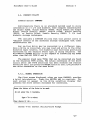
PREFACE
Thank you for purchasing Personal Micro Computer's MicroMate
computer. The MicroMate User's Guide, written for the model PMC101, contains instructions for installing the PMC MicroMate
system. The MicroMate computer system consists of a MicroMate
computer, Model PMC-lOl and a Qume terminal, Model QVT-l02. The
User's Guide consists of six sections plus Appendices.
Section 1
outlines operational features of the MicroMate system operations.
Section 2 leads the user step by step through the preliminary
unpacking, installing, and power-on procedures nec~ssary to run
the PMC MicroMate system.
Section 3 covers the installation of
optional equipment.
This section also mentions terminals other
than the Qume.
Section 4 discusses the Software utilities
supplied exclusively by PMC. Section 5 treats the differences
between standard CP/M Plus and the CP/M PLUS version being used
on the MicroMate. Section 6 contains technical information for
the advanced user, and the Appendices offer technical assistance.
PMC has also included a glossary at the end to help you with the
terminology used in this Guide.
ii
COPYRIGHT
Copyright (c) 1983 by Personal Micro Computers. All
rights reserved.
No part of this p'ublication may be
reproduced, transmitted, transcrl.bed, stored l.n a
retrieval system, or translated into any language or
computer language, in any form or by any means,
electronic, mechanical, magnetic, optical, chemical,
manual or otherwise, wit.hout the prior written
permission of Personal Micro Computers, 475 Ellis
Street, Mountain View, California, 94043.
DISCLAIMER
Personal Micro Computers makes no representations or
warranties with respect to the conEents hereof and
specifically disclaims any implied warranties of
-merchantabi li~y or fitness f or any particular purgose.
Further, Personal Micro Computers reserves the rignt to
revise chis publication and ~o make changes from tl.me to
time in the content hereof without obligation of
Per~opal Micro Computers to notify any person of such
reVl.Sl.on or changes.
TRADEMARKS
CP/M is a registered trademark of Digital Research.
CP/M PLUS, DDT, LINK-80, RMAC and SID are trademarks of
Digital Research.
TLMAKER is a trademark of Peter
ROl.zen.
Zilog and Z80 are registered trademarks of
Zilog Inc. MicroMate is a trademark of Personal Micro
Computers, Inc.
DISCLAIMER OF WARRANTY
No warranties are made with respect to the Software
utilities provided by Personal Micro Computers.
LIMITATIONOF.LIABILITY
The foregoing warranty is in lieu of all other
warranties expressed or implied, including, but not
limited to the l.mplied warranties of merchantability and
fitness for a particular purpose.
In no event will
Personal Micro Computers oe liable for consequential
damages even if it fias been advised of the possibility
of such damages. The MicroMate User's Guide has been prepared using the
MicroMate computer and is printed in the United SEates
of America.
Third Edition: October 1983
iii
TAB L E
o
F
CONTENTS
-------
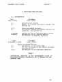
1. INTRODUCTION •••••••••••••••
1.1. PHYSICAL DESCRIPTION ••••••
. ....................... .. 1
.1
1.2. SYSTEM FEATURES •••••••••••
.2
1.3. SOFTWARE FEATURES ••••••••••••••••••••••••••••
•2
1.4. SPECIFICATIONS •••••••••••••••••••••••••••
.4
· . . . . . ..
1.4.1. MICROMATE COMPUTER SPECIFICATIONS.
1.4.2. QUME TERMINAL SPECIFICATIONS •.••••
.4
.4
..... ..
··.....
2. INSTALLATION •••••••••••••••••••••••••
..5
2.1. UNPACKING •••••••••••••••••••••••
• .5
2.2. CARE AND HANDLING OF DISKETTES ••
• • • • • • • • •5
2.3. INTERCONNECTING ••••••••••••••••••••••••••••••••••••••• 7
2.4. POWER-ON PROCEDURE.
• • • • • • • • • • • • • • • • • • • • • • • • • • • •8
2.4.1. TERMINAL ••••
• • • • • • • • • • • • • • • • • • • • • • • • • • • •8
2.4.2. COMPUTER ••••
••••••••••••••••••••••••••••• 8
2.5. BOOT PROCEDURE (Loading the Operating System) ••••••••• 9
2.6. MASTER DISKETTE BACKUP PROCEDURES.
.11
2.6.1. FORMATT ING •••••••••••••••••••••••••••• · ..... •• 11
2. 6 .2. BACKUP.............
• ••••••••••••••••••• •• 13
2.7. CONFIGURATION PROCEDURES ••••••••••••••••••••••••••••• 16
2.8. POWER-OFF PROCEDURE •• '. • • • • • • • • • • • • • • •
• ••••• 17
2 •. 9. DAY-TO-DAY POWER-ON/OFF PROCEDURES •••••••••••
· ... .. 18
2.9.1. POWER ON AND BOOT PROCEDURE.
· ... .. 18
2.9.2. POWER-OFF PROCEDURE •••••••••
.18
· . . ..
3. INSTALLING OPTIONAL EQUIPMENT.
.19
3.1. TERMINAL •••••••••
.19
3.2. DISK DRIVES •••••
· ...... . 21
3.3. PARALLEL PRINTER.
.22
. • • • • • • • • • • • • • . • • • • • . • • . • • • • -.22
3.4. SERIAL PRINTER.
3.5. MODEM ••••••••••
.22
. . . . . . . . . .. .
. . . . . . . . . . . . .. . . . . . . . . . . . . . . . . . . .
4. SOFTWARE UTILITIES ••••••••••••••••••••••••••••••••••••••• .23
4.1. FORMAT UTILITy •••••••••••••••••••••••••••••••••••••• • 23
4.2.
4.3.
4.4.
4.5.
4.6.
4.1.1. 'NORMAL OPERATION •••
• 24
4.1.2. ADVANCED OPERATION ••
.27
BACKUP.UTILITY •••••••••••••
.29
CONFIG UTILITy ••••.••.••••••
• 39
4.3.1. TERMINAL & MODEM GROUP ••••••••• ' •••••••••••••• .40
4.3.2. DRIVE GROUP •••••••••••••••••••••••••••••••••• • 44
4.3.3. OTHER MENU OPTIONS ••
• 45
CONVERT UTILITy •••••••••••
.47
4.4.1. NORMAL OPERATION •••
.47
4.4.2. ADVANCED OPERATION.
.49
COPYFIL UTILITY.
.51
SYSTEST UTILITy ••••••••••••
.53
·....
'
. . . . . . . .. .
. . . . .. . . . . . . . .
~
iv
~
~
5. DEVIATIONS FROM CP/M PLUS
5.• 1. DOCUMENTATION ••••••••.
5.2. DEVICES ••••••••••••.•.
5.2.1. DEFAULT POWER-ON PARAMETERS.
5.3. FILE NAME DIFFERENCES ••••••
5.4. REAL TIME CLOCK.
5.5. PROTOCOLS ••
5.6. PARITy •••••
• •• 55
.55
• .57
.57
.58
.58
• .59
.61
6. TECHNICAL REFERENCE.
• .65
6.1. BANK SWITCHING •••.•••
•• 65
6.2. TYPE A DISKETTES.
.68
.68
6.2.1. PHYSICAL SPECIFICATIONS.
6.2.2. DPB •••••••••••••••••••••
• .68
6.2.3. FORMATTING INFORMATION ••
• •••. . 69
6.3. TYPE BYTE •••••••• ~ •••••••••••••
• .70
6.3.1. "TYPE" byte used in DPH.
· •... . 70
6.3.2. SAMPLE Disk Parameter Header ••
• .71
6.3.3. "TYP" byte used in DPB •••••••
• .71
6.3.4. SAMPLE Disk Parameter Block ••
• .71
6.4. BOOT CYLINDER •••••••••••••••••••••• ~.
• ••••• 72
6.4.1. TRACK 0, SECTOR 1
Disk Load Information ••
.73
6.4.2. TRACK 0, SECTOR 1
Serial Initialization.
.74
6.5. BOOT SEQUENCE.
••••••••••••••• 75
6.5.1. ROM ••••
• ••••••••••• 75
6.5.2. CPMLDR.
• .75
6.5.3. BIOS BOOT ••
• •• 76
6.6. MODEM PORT SPECIFICATIONS ••
• .77
6.6.1. PORT VALUES ••••••••••
.77
6.6.2. BIT POSITIONS •••••••
• .77
..78
6.6.3. SETTING BAUD RATES ••
. ....
·..
..
·.....
v
Appendices
A. CABLES & CONNECTORS ••••••••
••••••••••••••••••••••••••• 79
• •••••••••••••••••••• ·•. 79
A.l. RS-232 TERMINAL CABLE.
A.2. RS-232 MODEM CABLE ••••••••••••••••••••••••••••••••••• 80
A.3. RS-232 PRINTER CABLE ••••
• ." ••••••••••• ~ ••• ' ••• ' •••••.81
A.4. RS-232 CONNECTOR ••••••••••••••••••••••••••••••••••••• 82
A.S. PARALLEL PRINTER CABLE ••••••••••••••••••••••••••' ••••• 83
A.6. ADD-ON DISK DRIVE CABLE ••••••••••••••••••• ~ •••••••••• 84
A.7. 34-PIN EDGE CONN'ECTOR •••••
• ....•...•....•.....• . 85
• ••••••••••••••••••.• "86
A.8. INTERFACE CONNECTOR •••••
.87
A.9. CONNECTOR LOCATIONS.
. . . . . . . . . . . . . . . . . ..
B. ERROR MESSAGES ••••••••••••••••••••••••••••.•••••••••••••••• ~ 9
B.l. BACKUP utility ERROR MESSAGES •••••••••••••••••••••••• 89
B.2. CONFIG-Utility-ERROR-MESSAGES •••••••••••••••••••••••• 91
B.3. DISK RELATED ERROR MESSAGES •••••••••••••••••••••••••• 92
B.4. SYSTEST_Utility_ERROR_MESSAGES ••••••••••
..93
C. PROBLEMS AND POSSIBILITIES.
.................. ....... . .'-.97
D. SUGGESTED READING ••••••••••••••••••••••••••••••••••••••••• 99
GLOSSARY •
•
•
•
•
•
•
•
•
•
•
•
•
•
•
•
•
•
•
•
•
•
•
•
•
•
•
•
•
• "•••••• e .•••••••••••••••
.101
Index ......................................................... 109
vi
-L-I S
--T
o
F
FIGURES
------
1-1: MicroMate Computer System.
2-1:
2-2:
2-3:
2-4:
.1
..... ................. .....
...... . ..... ............
.66
......... ..·........
.67
.. .
.
.
.
..... ··........ .70
.5
5 1/4 Inch Diskette.
Front Panel •••••••••
•6
Rear Panel ••••••••••••••••••••
.6
Rear Panel of Qume Terminal •••••••••••••••••••••••••••••• • 6
6-1: . Memory Map-First 64K •••••••
6-2: Memory Map-Second 64K ••••••
6-3: . TYPE Byte-Bit Designations.
A-I.: Standard RS-232 Terminal Cable ••••••••••••••••••••••••••• 79
A-2: Standard RS-232 Modern Cable •••••••••••••••••••••••••••••• 80
A-3: "Null-Modem" RS-232 Printer Cable •••••••••••••••••••••••• 81
A-4: Male RS-232 Connector •••••••••••••••••••••••••••••••••••• 82
A-5: Parallel Printer Cable •••••••••••••••••••••••••••••••• ~ •• 83
A~6: Disk Drive Cable ••• ~ ••••••••••••••••••••••••••••••••••••• 84
A-7: 34 pin Female Edge Connector ••••••••••••••••••••••••••••• 85
A-8: Female Interface Connector ••••••••••••••••••••••••••••••• 86
A-9: Connector Locations •••••••••••••••••••••••••••••••••••••• 87
vii
o
F
SCREENS
------
2-1: Initial Boot Display ••••••• ~ •••••••••••••••••••••••••••••• 9
2-2: Intermediate Boot Display •••••••••••••••••••••••••••••••• 10
2-3: Final Boot Display ••••••••••••••••• ; •• ~~ ••••••••••••••••• lO
4-1: Format utility-Main Menu ••••••••••••••••••••• ~· ••••••••••• 24
4-2: Format utility-Drive Selection ••••••••••••• ~ •• ~ •••••••••• 24
4-3: Format Utility-Final Prompt ••••••••••••••••••••••••••••• 25
4-4: Format Utility-No Errors ••••••••••••••••••••••••••••••••• 25
4-5: Format utility-Typical Errors •••••••••••••• ~ ••••••••••••• 26
4-6: Format utility-Advanced Command ••••••••••••••••••• ~ ••••• ·.27
4-7: Backup Utility-Source Drive •••••••••••••••••••••••••••••• 30
4-8: Backup utility-Destination Drive ••••••••••••••••••••••••• 30
4-9: Backup utility-Verification Mode ••••••••••••••••••••••••• 3l
4-10: Backup utility-Confirmation Prompt •••••••••••••••••••••• 3l
4-11 : Backup, Utility-Source Diskette Prompt •••••••••••••••• ·.31
4-12: Backup utility-Source Diskette Error •••••••••••••••••••• 32
4-13: Backup Utility-Destination Diskette Prompt •••••••••••••• 32
4-14: Backup utility-Destination Diskette Error •••••••••• ~ ••• ~33
4-15: Backup Utility-Destination Diskette Error ••••••••••• ~ ••• 33
4-16: Backup Utility-Multiple Drive Cylinder·Display •••••••••• 34
4-17: Backup utility-Single Drive Cylinder Display •••••••••• 35
4-18: Backup Utility-Single Drive Error Display ••••••••••••••• 36
4-19: Backup Utility-Wrong Diskette Prompt •••••••••••••••••••• 36
4-20: Backup utility-Repeat Prompt •••••••••••••••••••••••••••• 37
4-21: Backup utility-Confirmation Prompt •••••••••••••••••••••• 37
4-22: Backup Utility-Exit Prompt •••••••••••••••••••••••••••••• 38
4-23: Config Utility-Main Menu •••••••••••••••••••••••••••••••• 40
4-24: Config utility-Possible Baud Rates •••••••••••••••••••••• 4l
4-25: Config utility-Control Bits Prompt •••••••••••••••••••••• 4l
4-26: Config Utility-Word Length Prompt ••••••••••••••••••••••• 42
4-27: Config Utility-Stop Bits Prompt ••••••••••••••••••••••••• 42
4-28: Config utility-Parity Prompt •••••••••••••••••••••••••••• 42
4-29: Config Utility-Even/Odd Prompt •••••••••••••••••••••••••• 43
4-30: Config utility-DTR Prompt ••••••••••••••••••••••••••••••• 43
4-31: Config utility-RTS Prompt ••••••••••••••••••••••••••••••• 43
4-32: Config utility-Drive Quantity Prompt •••••••••••••••••••• 44
4-33: Convert utility-Drive Prompt •••••••••••••••••••••••••••• 47
4-34: Convert utility-Emulation TYPE Selection •••••••••••••••• 48
4-35: Convert utility-Conversion Confirmation ••••••••••••••••• 48
4-36: Convert utility-Cancellation Confirmation ••••••••••••••• 49
4-37: Convert utility-Conversion Confirmation, Advanced ••••••• 49
4-38: Convert utility-Cancellation Confirmation, Advanced ••••• 50
4-39: Copyfil utility-SOURCE diskette prompt •••••••••••••••••• 5l
4-40: Copyfil utility-DESTINATION diskette prompt ••••••••••••• 52
4-41: Copyfil utility-SYSTEM diskette prompt •••••••••••••••••• 52
viii
MicroMate User's Guide
Section 1
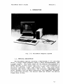
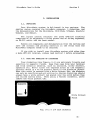
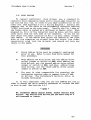
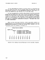
1. INTRODUCTION
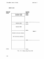
Fig. 1-1: MicroMate Computer System
1.1. PHYSICAL DESCRIPTION
The MicroMate cabinet contains a half-height 5 1/4 inch disk
drive, a single board computer using a zaO-A microprocessor, and
a power supply. The front panel of the cabinet incorporates a
RESET button, a disk drive slot for a 5 1/4 inch diskette, a
drive door handle, a power indicator light, and a disk drive
activity indicator light (See Figure: 2-2).
The back panel
features two serial connectors: one labelled IITERMINAL II , the
other IIMODEMII~ and two edge connectors, one labelled IIPRINTER II
for a parallel printer, the second labelled IIDISKS II ' for add-on
floppy disk drives.
-1-
MicroMate User's Guide
section 1
1.2. SYSTEM FEATURES
The MicroMate computer, shipped as a stand alone system, is
designed to be used with an asynchronous terminal as a high speed
independent work station.
It is easy to transport the computer
from one work station to another because of its small size.
The MicroMate computer features a Z80-Amicroprocessor
rq.nning at 4 Mhz, 128 Kilobytes of Dynamic bank sW,itched RAM, a
half-height 5 1/4 inch floppy disk drive with 400 Kilobytes of
storage and a Real Time Clock, as well as the CP/M PLUS Operating
System.
In addition to the basic configuration, the MicroMate is
compatible with a wide range of products as well, for example:
An internal
capabilities for
the addition of
eight-inch disk
networks.
asynchronous serial terminals
parallel or serial printers
up to four disk drives
modems
asynchronous serial peripherals
interface connector offers further expansion
the MicroMate computer. This connector permits
other peripherals such as hard disk drives,
drives, voice and music synthesizers, and
·1.3. SOFTWARE FEATURES
PMC includes five software diskettes with the MicroMate
computer. The diskettes are labelled:
"CP/M 3.0 SYSTEM MASTER"
"CP/M 3.0 SOURCE MASTER"
"T/MAKER MASTER"
"ELECTRIC WEBSTER MASTER"
"CBASIC MASTER"
Each diskette contains the CP/M PLUS operating system
permitting any program on the five diskettes to load and run with
a single disk drive system.
PMC has implemented the banked
version of CP/M PLUS using l28K-bytes of Ram and three types of
serial protocol: XON/XOFF, CTS/RTS and DTR/DSR.
In order to simplify the initial installation of the system,
the parameters used for booting are different on each diskette.
All Software utilities supplied, which are menu driven for ease
of use, include extensive error trapping and messages.
-2-
MicroMate User's Guide
Section I
The "SYSTEM MASTER" diskette contains programs and Software
utilities used in day-to-day computing.
Some of the utilities
included with this diskette are:
command help, diskette
formatting, high-speed full diskette copying, single-drive
single-file copying, drive conversion (which permits reading from
and writing to diskettes of other manufacturers), power-on
parameter configuration, and system test.
The "SOURCE MASTER" diskette that contains the Bios source
code files also has the necessary programs to assemble the source
code into a working operating system.
The "T/MAKER" diskette contains all of the files relating to
the T/Maker electric spreadsheet and word processing program.
The "CBASIC" diskette contains all of the files necessary to
compile and run Basic programs.
The "ELECTRIC WEBSTER" diskette all of the files necessary
to check and correct the spelling of any ASCII file.
-3-
MicroMate User's Guide
Section 1
1.4. SPECIFICATIONS
.1.4.1. MICROMATE COMPUTER SPECIFICATIONS, Model PMC-lOl
Processor
RAM
ROM
Disk Capacity
Serial Ports
Parallel Ports
Printer Port
Dimensions
Weight
Power
zaOA, 4Mhz
l28K-bytes, bank switched
4K-bytes, auto boot
One internal drive, 400K-bytes
Three Qptional drives
Two 50 to 19,200 baud, asynchronous
128 bidirectional available
Centronics parallel type
3 1/2 wide x 6 high x 15 inches deep
10 pounds
117 VAC SO/60Hz 60 Watts
1.4.2. QUME TERMINAL SPECIFICATIONS, Model QVT-102
Screen Size
Display Format
Character Size
Attributes
Keyboard
Character Set
Interface
Protocol
Baud Rates
Dimensions
Weight
Power
-4-
12 inch non-glare green screen
24 x 80, 25th status/setup line
7 x 9 matrix in a 9 x 12 cell
Blink, blank, underline, reverse, dim
Low profile, detached, as-key QWERTY type
Numeric keypad, function & cursor control
keys, key click and auto repeat
96 ASCII, 32 control, 15 graphic
EIA RS-232-C, Terminal & Auxiliary
DTR, Xon/Xoff or both
50 to 19,200
r
Keyboard: 18 wide x 1 1/2 high x12· inches deep
Screen: 13 wide x 14 high x 12 inches deep
Keyboard & Screen Module: 22 pounds
l17VAC SO/60Hz 30 Watts
·MicroMate User's Guide
Section 2
2. INSTALLATION
2.1. UNPACKING
Your MicroMate system is delivered in two cartons.
The
smaller carton contains the MicroMate computer, 5 diskettes, and
the documentation for the MicroMate, CP/M PLUS, T/Maker, Electric
Webster, and CBasic.
The larger carton contains the Qume QVT-I02 terminal
comprised of an adjustable tilting screen and an 85-key keyboard,
an RS-232 cable, and the Qume manual.
Remove all components and documentation from the cartons and
save the cartons and packing material in the event that the
MicroMate computer needs to be returned.
If you wish to install your MicroMate system with other than
a Qume QVT-I02 terminal, please read Section 3 before proceeding.
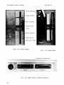
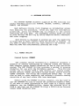
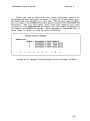
2.2. CARE AND HANDLING OF DISKETTES
Your diskettes (See Figure: 2-1) are extremely fragile and
sensitive to magnetic field~. Keep them away from your terminal
and from metallic objects, such as scissors, screw drivers,
speakers etc. Never touch the exposed areas of the magnetic
surface. There is a write protect notch in the diskette jacket.
When this notch is covered with a Write Protect Tab, the diskette
can only be read from and not written to. Master diskettes should
always have a write protect tab placed over the notch before they
are stored safely away.
When u$ing a Master diskette, never
remove the write protect tab.
Write Protect
Notch
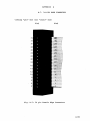
Fig. 2-1: 5 1/4 Inch Diskette
-5-
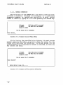
MicroMate User's Guide
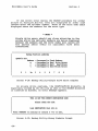
Section 2
Power Switch
Power Light
Door Handle
Disk Drive
Slot
-Reset Button
Disk Drive
Fig. 2-2: Front Panel
Fig. 2-3: Rear Panel
Terminal Connector
Fig. 2-4: Rear Panel of Qume Terminal
-6-
MicroMate User's Guide
Section 2
2.3. INTERCONNECTING
1)
Set the QVT-I02 terminal and the MicroMate computer on
a very stable and solid work surface. The two pieces
must always be a minimum of six (6) inches apart.
2)
Be sure the power switches on the rear of the terminal
and the computer are in the OFF position before
plugging the terminal and the computer power cords into
grounded AC outlets.
It is often convenient to have the computer and all
peripherals plugged into an AC power strip so that
they can be all turned on or off at the same time.
3)
Plug the loose end of the coiled keyboard cable into
the matching connector located on the left front corner
of the terminal base.
4)
Plug either end of the RS-232 cable (round cable) into
the connector labelled "EIA" and found on the rear
panel of the Qumeterminal.
5)
Plug the other end of the RS-232 cable into the
connector labelled "TERMINAL" and found on the rear
panel of the MicroMate cabinet.
For permanent installation it is advisable that the
lock-down screws on each RS-232 cable connector be
screwed into the rear panel mounting studs.
.
Open the door of the built in disk drive (A: drive) by
pressing down on the left side of the door handle.
Pull the cardboard shipping diskette straight out to
remove it. This cardboard diskette should be kept with
the rest of the packing materials.
-7-
MicroMate User's Guide
Section 2
2.4. POWER-ON PROCEDURE
ALWAYS turn on peripheral devices such as the terminal,
modem and printer before powering-on the MicroMate computer.
2.4.1. TERMINAL
6)
Move the terminal power switch, located on the rear of
the base, to the ON position.
7)
After a short delay, the beeper sounds.
8)
The cursor appears in the upper left corner of the
.screen while the status line spreads across the bottom
of the screen.
9)
If an error message appears or the cursor does not
appear, consult your terminal manual.
2.4.2. COMPUTER
10)
. Move·the MicroMate power switch, located on the rear
panel, to the ON position.
11)
The power indicator on the upper left front panel
~ill illuminate.
12)
The drive activity indicator on the front of the A:
drive will blink.
13)
Press the 'RESET :button·located on the frbnt panel.
14)
If the A: drive activity light does not blink, move the
power switch to the OFF position. Repeat from step 10.
If all the steps above fail,
-8--
consult your dealer.
MicroMate User's Guide
Section 2
2.5. BOOT PROCEDURE (Loading the Operating System)
15)
Locate the diskette
16)
Remove the diskette from its sleeve, being careful to
handle the diskette by the label end only.
17)
Hold the diskette so the label side is facing right and
the silver write protect tab is up.
18)
Insert the diskette slowly into the slot in the front
of the A: drive. The diskette must be fully inserted.
19)
Close the drive door by grasping the lower edge of the
door lever and in a smooth motion, swing the handle
left and up until it is in a horizontal position.
labe~led
"CP/M 3.0 SYSTEM MASTER."
Clicking noises emanate from the drive. . After a short
delay the terminal screen will display the information
shown as Screen: 2-1, below~ after a second delay, the
screen appears as Screen: 2-2. The screen will look
like Screen: 2-3 after the system boots.
20)
The "A> " is called the A>
the cursor.
prompt~
the" " represents
CP/M V3. 0 IDader
Copyright (C) 1982, Digital Research
6IKTPA
Screen 2-1: Initial Boot Display.
-9-
MicroMate User's Guide
Section 2
CP/M V3. 0 Loader
Copyright (C) 1982, Digital Research
6lKTPA
128K RC-10l
Screen
CP/M 3.0 ,with extended Bios for MicroMate -Vers 3.02~2:
Intermediate Boot Display •
.----------------CP/M V3. 0 ,Loader
Copyright (C) 1982, Digital Research
6IKTPA
l28K PK:-10l
CP/M 3.0 with extended Bios for Micrd-Bte -Vers 3.0-
A>
Screen 2-3: Final Boot Display.
-10-
MicroMate User's Guide
Section 2
2.6. MASTER DISKETTE BACKUP PROCEDURES
Please BACKUP your five master diskettes now. It is very
important to make backup copies of each original diskette at the
time of your first successful installation. The SYSTEM MASTER
diskette has two programs, FORMAT and BACKUP, which enable you to
prepare new diskettes and BACKUP each of your master diskettes.
You will need ten blank Double Sided, Double Density diskettes
enabling you to make two copies of each master diskette. Follow
the steps below very care·fully and as soon as you have finished
backing up or copying your master diskettes, put the originals in
a very safe, cool, dry place.
*
NOTE
*
The RETURN key on the Qume terminal is labelled -J .
The ENTER key on the numeric keypad may also be used.
2.6.1. FORMATTING
Now that you have signed on by allowing the system to boot,
you have the A> prompt on the screen; follow the instructions
. below for FORMATTING your blank disks:
21)
Obtain ten blank Double Sided, Double Density, 40 track
5 1/4 inch, Soft-Sectored diskettes.
22)
If the SYSTEM MASTER diskette is not already in the A:
drive, insert it into the A: drive, and close the door.
Type control C (AC) by holding down the key marked Ctrl
while simultaneously pressing the key marked C.
23)
After the A> prompt, type in the word FORMAT. Do not
leave a space between the A) and FORMAT. Either upper
case or lower case letters may be typed. The screen
should appear as. follows:
A> format
24)
Press the RETURN key
screen appears.
(~).
The FORMAT introduction
If the introduction screen fails to appear, be sure the
SYSTEM MASTER diskette is inserted correctly in the A:
drive and the disk drive door is closed. Repeat from
step 22.
-11-
MicroMate User's Guide
Section 2
25'>
After reading the introduction screen, press the RETURN
key to advance to the main menu screen.
26)
At the main menu screen, type.an F for Format. Press
the RETURN key.
27)
When the drive selection menu appears on the screen,
type an A. Press the RETURN key.
28)
The next screen instructs you to insert the Double
Sided diskette you wish to format into the A: drive.
Remove the SYSTEM MASTER diskette, replace in sleeve,
and insert one of the blank diskettes into the A: drive
at this time.
DO NOT press the RETURN key before inserting the blank
disk.
The screen first displays the number of each track on
side 0, and then on side 1 of the diskette as it
formats. The counting of the tracks changes rapidly on
the screen as the drives make a clicking sound.
29)
After both'sides are formatted, every track on both
sides is verif ied for correct formatting.
If . the
format of any track is incorrect, a coded error message
appears next to the track number.
30)
Upon completion of the formatting and verification
procedure, the screen prompts you to press RETURN.
Before pressing RETURN, check the screen for any errors
which appear as a code word bounded by asterisks (**)
next to a track number.
3l)-Press the RETURN keYI the main menu reappears.
-12-
32)
If any errors are reported, leave the diskette in the
A: drive. Try formatting the diskette one more time by
repeating from step 26. If errors reappear, remove the
diskette, discard it, and skip to step 34.
33)
Remove the diskette from the A:
sleeve, and set aside.
34)
In~ert another blank diskette into the A: drive.
Repeat steps 26 through 33 until you have formatted 10
diskettes without any errors.
drive,
replace in
MicroMate User's Guide
35)
Section 2
When the final diskette is prepared for use, remove the
diskette, reinsert the SYSTEM MASTER diskette, close
the drive door, and type an E at the main menu to exit
from the Utility.
The A> prompt should now be visible on your screen.
You are now ready to make BACKUP copies of your master
diskettes.
2.6.2. BACKUP
The BACKUP Utility is designed to make copies of your master
diskettes. It may only be used with a previously formatted
diskette.
36)
To begin the BACKUP Utility, type the word BACKUP at
the A> prompt, and press the RETURN key (~).
The BACKUP introduction menu appears on the screen.
PLEASE read the directions carefully. The following
screens instruct you when to remove or insert the
SYSTEM MASTER diskette (called the SOURCE diskette),
and when to insert or remove the newly formatted
diskette (called the DESTINATION diskette).
In case the introduction screen fails to appear, be
sure the SYSTEM MASTER diskette is correctly inserted
in the A: drive. Go back to step 36.
37)
To advance to the next screen, after reading the
Introduction screen, press the RETURN key.
38)
The next screen asks whether or not the data is to be
verified. Type a Y. Press the RETURN key.
39)
On the next screen, confirm using only
typing a Y.
Press RETURN.
the A: drive by
-13-
MicroMate User's Guide
40)
Section 2
When prompted to load the SOURCE diskette into drive
A:, be sure the SYSTEM MASTER diskette is in the A:
drive.
Press RETURN.
'
Ten "cylinders" are read from the SOURCE diskette into
the computer. The number of each cylinder appears on
the screen as it is being read from the disk. Watch
the screen as the numbers are displayed; look for any
lower case letters that may appear after a number. If
any letters appear after a number, an error has
occurred. Note the error and proceed.
41)
When prompted to load the DESTINATION diskette into
drive A:, remove the SYSTEM MASTER diskette, insert a
newly formatted diskette, and close the drive door.
Press RETURN.
Ten cylinders are written to the DESTINATION diskette.
The number of each cylinder written appears on the
screen. If no letters appear after any of the numbers,
the information has been written correctly.
42)
Repeat steps 40 and 41 three more times so that all 40
cylinders are copied.
Insert the SYSTEM MASTER
diskette ,when prompted for the SOURCE diskette, and
insert the newly formatted diskette when -prompted for
the DESTINATION diskette.
43)
After the last cylinder has
DESTINATION diskette, 'the screen
repeat the backup function.
reported in step 40, type Y. Try
this diskette one more time
through 43.
44)
DO NOT answer the prompt until you remove the diskette
from the A: drive, and replace it in the envelope.
been written to th'e
asks whether or not to
If any errors were
the BACKUP Utility for
by repeating step 38
Prepare a labeL by writing "CP/M 3.0 SYSTEM" on a selfadhesive label before aff ixing it to the first backup
diskette.
-14-
45)
Type Y. Press RETURN, and repeat steps 38 through 44
using another of the newly formatted diskettes for the
second backup copy of the SYSTEM MASTER diskette.
46)
Replace the SYSTEM MASTER diskette in its envelope and
set aside.
MicroMate User's Guide
Section 2
47)
Type Y. Press RETURN, and repeat steps 38 through 46
using the SOURCE MASTER diskette as the SOURCE diskette
instead of the SYSTEM MASTER diskette. Label these
backup copies "SOURCE. II
48)
Type Y. Press RETURN, and repeat steps 38 through 46
using the the T/MAKER MASTER diskette instead of the
SOURCE MASTER diskette.
Label these backup copies
liT/MAKER. II
49)
Type Y. Press RETURN, and repeat steps 38 through 46
using the the ELECTRIC WEBSTER MASTER diskette instead
of the SOURCE MASTER diskette.
Label these backup
copies "ELECTRIC WEBSTER."
50)
Type Y. Press RETURN, and repeat steps 38 through 46
using the the CBASIC MASTER diskette instead of the
SOURCE MASTER diskette.
Label these backup copies
"CBASIC."
51)
Now that you have made two backup copies of all five
master diskettes, when the screen prompts whether or
not to repeat function, type N. Press RETURN.
When the screen prompts you to "Place SYSTEM disk in
A:", insert one of the newly created CP/M 3.0 SYSTEM
diskettes into the A: drive, close the door and press
RETURN. The A) prompt reappears on your screen.
52)
Place your five master diskettes in a very safe, cool,
dry place~ they will not be needed for any further
operations. Use the backup copies just created for all
of your day-to-day computer work. The master diskettes
should only be used to make new BACKUP copies.
You are now ready to configure the power-on parameters
on the CP/M 3.0 SOURCE, T/MAKER, ELECTRIC WEBSTER and
CBASIC diskettes just created.
-15-
MicroMate User's Guide
Section 2
2.7. CONFIGURATION PROCEDURES
The CONFIG utility is used to change the power-on parameters
on each of the newly created CP/M 3.0 SOURCE, T/MAKER, ELECTRIC
WEBSTER, and CBASIC diskettes in order to match the parameters of
the CP/M 3.0 SYSTEM diskette.
53)
To begin the CONFIG utility insert the CP/M 3.0 SYSTEM
diskette in the A: drive. Type the word CONFIG after
the A> prompt. Press the RETURN key (~).
The CONFIG introduction menu will appear on the screen.
If the introduction screen fails to appear, be sure the
CP/M 3.0 SYSTEM diskette is correctly inserted in the
A: drive, and repeat from step 53.
54)
After reading the introduction screen, press the RETURN
key.
The next screen is divided into two parts: the upper
portion of the screen displays the current power-on
settings~
the lower part of the screen is the main
menu.
55)
The Qume terminal, as shipped from the factory, is set
at 9600 Baud. This matches the current setting
displayed in the upper portion of your screen.
56)
Remove the diskette from the A: 'drive and replace it
with one of the CP/M 3.0 SOURCE diskettes just created.
57)
Select the <W>ri te option, by typing a Wand pressing
RETURN, to write the current 9600 baud setting to this
diskette.
The drive activity light illuminates for a brief period
and the main menu reappears.
58)
Repeat steps 56 and 57 for the second CP/M 3.0 SOURCE
diskette, both of the T/MAKER diskettes, both of the
ELECTRIC WEBSTER diskettes and both of the CBASIC
diskettes.
You now have 10 bootable diskettes:
Two CP/M SYSTEM
diskettes, two CP/M SOURCE diskettes, two T/MAKER diskettes, two
ELECTRIC WEBSTER diskettes, and two CBASIC diskettes. Anyone of
these diskettes may be used to boot the system when you first
turn it on.
Please proceed to the next steps for details on
powering off your computer system.
-16-
MicroMate User's Guide
Section 2
2.8. POWER-OFF PROCEDURE
59)
Make sure that you are at the A> prompt.
60)
Open the disk drive door.
61)
Remove the diskette from the drive and replace it in
its sleeve.
62)
Turn OFF all components. There is no required sequence
for turning off the computer or peripherals.
You are now ready to use your MicroMate system. PLEASE Read
the CP/M PLUS Documentation for details on using CP/M.
Some
sections of the CP/M PLUS documentation do not apply to the
MicroMate PMC-IOI system. Section 5 of this User's Guide lists
the inapplicable sections and refers you to an alternate section
in this Guide. Read the T/MAKER III REFERENCE MANUAL, the
ELECTRIC WEBSTER USER'S GUIDE, and the CBASIC MANUAL for
information on using these programs.
WARNING
If you leave your diskette(s) in the drivels) when you
power OFF, information on the
diskette(s) MAY be ERASED.
-17-
Section 2
MicroMate User's Guide
2.9. DAY-TO-DAY POWER-ON/OFF PROCEDURES
Once you have created backup copies of your master diskettes
and have configured them for your system, use ONLY the backup
copies for your day-to-day computing. The following steps guide
you through a normal start up and power down.
2.9.1. POWER ON AND .BOOT PROCEDURE
1)
Refer to Section 2.4.
2)
Use any boot diskette configured for your system.
3)
Hold the diskette so the label side is facing right and
the write protect notch is up.
4)
Insert the diskette slowly into the A: drive slot.
S)
Close the drive door.
6)
The A> prompt appears after the sign-on message.
2.9.2. POWER-OFF PROCEDURE
1)
Make sure that you are at the A> prompt.
2)
Open the disk drive
3)
Remove the diskette(s) from the drive(s) and replace
i t(them) in i ts(their) . sleeve( s).
4)
Turn off all power switches.
door(s)~
WARNING
If you leave your diskette(s) in the drivels) when you
power OFF, information on the diskette(s) MAY be ERASED.
-18-
Section 3
MicroMate User's Guide
3. INSTALLING OPTIONAL EQUIPMENT
3.1. TERMINAL
For terminals other than the Qume QVT-l02, consult your
terminal manual and set the following parameters on your
terminal:
110, 300 or 9600 baud rate
8 bi t word length
Bit 8 set to a
1 stop bit
No parity
Full duplex mode
No protocol (XON/XOFF permissible)
Other terminal parameters should not affect the initial
start up procedures.
Each of the supplied master diskettes contains the CP/M 3.0
operating system and may be used to boot the system~ however,
each diskette will boot using a different baud rate.
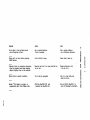
If your terminal is set for 300 baud, use the CP/M 3.0
SOURCE MASTER diskette~ if your terminal is set for 110 baud, use
the T/MAKER MASTER~ if your terminal is set for 1200 baud,use
the ELECTRIC WEBSTER MASTER~ if your terminal is set for 19200
baud, use the CBASIC MASTER~ or, if your terminal is set for 9600
baud, use the CP/M 3.0 SYSTEM MASTER diskette to boot the system.
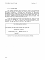
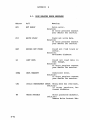
Terminal Baud Rate
Diskette Name
110
300
1200
9600
19200
T/MAKER MASTER
CP/M 3.0 SOURCE MASTER
ELECTRIC WEBSTER MASTER
CP/M 3.0 SYSTEM MASTER
CBASIC MASTER
Table 3-1
Diskette Selection for Boot Operation
-19-
MicroMate User's Guide
Section 3
After selecting the proper diskette, follow the procedures
in Section 2.5 and make suitable adjustments for use of your
own terminal and make the following specific changes:
In step 15, use your selected diskette instead of the SYSTEM
MASTER.
Immediately after step 20, remove your selected diskette and
insert the SYSTEM MASTER. Type Control C <AC>
After step 53, but before step 54, insert your selected
diskette.
In step 55, substitute your terminal settings.
If your selected diskette is the SOURCE diskette, sUbstitute
SYSTEM for SOURCE in step 56 and step 58.
If your selected diskette is the T/MAKER diskette,
substitute SYSTEM for T/MAKER in step 58.
If your selected diskette is the ELECTRIC WEBSTER diskette,
substitute SYSTEM for ELECTRIC WEBSTER in step 58.
If your selected diskette is the CBASIC diskette, substitute
SYSTEM for CBASIC instep 58.
-20-
MicroMate User's Guide
Section 3
3.2. DISK DRIVES
To connect additional
disk drives, use a standard 34
conductor dr i ve expansion cable with a 34 pin edge connector on
one end and one, two, 0r three 34 pin edge connector(s) on the
other end. (See Appendix A for a wiring diagram.) Connect the
computer end of the cable to the MicroMate's connector labelled
"DISKS" and found on the rear panel.
Usually the Pin I edge of
the ribbon cable is marked by a different or darker color. When
plugged in, Pin 1 of the connector must be down, and the cable
often exits from the left side of the connector.
If you are not
sure about the exact location of Pin 1 on your cable, consult
your dealer.
If the add-on disk drives are located on the right
side of the computer as viewed from the front, the other
connector(s) plug into the drive(s) and should not have any
twists in the cable.
IMPORTANT
a)
Every add-on drive must be properly configured
prior to use. Refer to your disk drive manual for
this procedure.
b)
When adding one disk drive, set the add-on drive
select jumper or switch to DS2; when adding two
disk drives, set the second add-on drive select
jumper or switch to DS3; and when adding three
disk drives, set the third add-on drive select
jumper or switch to DS4.
c)
The user is also responsible for removing the
termination resistor pack or jumpers from all addon drives.
The MicroMate's built-in drive is
already terminated.
It is very important that you run the CONFIG Utility in
order to change the drive quantity parameter to include the addon dis k d r i v e s. ( See Sec t ion 4.3.)
*
NOTE
*
We recommend adding Double Sided, Double Density disk
drives. Any add-on disk drives you use must step at 6
milliseconds or faster.
-21-
MicroMate User's Guide
Section 3
3.3. PARALLEL PRINTER
To connect a centronics type parallel printer, use a 34
conductor ribbon cable with a Centronics D-connector on one end
and a 34 pin edge connector on the other (available from PMC as
Part No.: CAB-aS).
Plug the edge connector end of the printer
cable into the MicroMate's connector labelled "PRINTER" and found
on the rear panel. Usually the Pin I edge of the ribbon cable is
marked by a different or darker color. When plugged in, Pin I of
the connector must be down, and the cable often exits from the
left side of the connector. If you are not sure about the exact
location of Pin I on your cable, consult your dealer.
The
printer end of the cable is a standard Centronics connector.
Consult your printer manual for proper connection. (See Appendix
A fqr a wiring diagram of a ~tandard Centronics printer cable.)
3.4. SERIAL PRINTER
To connect a serial type printer, generally, you use a
"flipped" or "Null-Modem" Asynchronous Serial RS-232 cable with
male connectors on both ends. Plug one end of the cable into the
connector of the MicroMate labelled "MODEM" and found on the rear
panel.
The other end of the cable connects to your serial
printer. Consult your printer manual for instructions on the
connecting and wiring of the DB-2S connector.
(See Appendix A
fora wiring diagram of a "flipped" RS-232 printer cable.)
Use the DEVICE Utility to set the logical LST: device to
MODEM and change the baud rate temporarily. (See the CP/M User's
Guide.) As shipped from the factory, the MicroMate's MODEM port
is set to 300 baud. The CONFIG Utility may be used to change the
power-on MODEM baud rate setting.
(See Section 4.3.)
3.5. MODEM
To connect a modem, use a standard Asynchronous Serial RS232 modem cable with male connectors on both ends. Plug one end
of the cable into the lower right connector labelled "MODEM" on
the rear panel of the MicroMate.
The other end of the cable
connects to your modem. Consul t your modem manual f or further
installation instructions.
(See Appendix A for a wiring diagram
of a standard RS-232 modem cable.)
Use the DEVICE utility to change the MODEM port baud rate
temporarily. (See the CP/M User's Guide.)
The MicroMate's MODEM
port, as shipped from the factory, is set to 300 baud.
The
CONFIG utility may be used to change the power-on MODEM baud rate
setting. If your communication program uses the Bios input
routines and requires a bit characters read the section on PARITY
(See Section 5.6.) To configure your communication program. (See
Section 6.6.)
-22-
Section 4
MicroMate User's Guide
4. SOFTWARE UTILITIES
The SYSTEM MASTER diskette supplied by PMC contains six
useful Software utilities: FORMAT, BACKUP, COPYFIL, CONVERT,
CONFIG, and SYSTEST.
Each Software Utility first displays an introductory screen
that explains the procedure.
After you read the information
presented, press the RETURN key to advance to the screen
containing the main menu.
The subsequent screens guide you step
by step through the utility by using complete menus, messages,
and .error trapping.
Each Utility is designed to provide you with the capability
of being able to abort (cancel) while the utility is running.
If
you need to abort the utility, type Control C by holding. the
Ctr1 key down and simultaneously pressing the C key.
4.1. FORMAT UTILITY
Command Syntax: FORMAT
The process called "formatting a diskette" prepares a
diskette to receive information by creating tracks and sectors.
Each computer system formats diskettes for use on that particular
system. The PMC FORMAT utility provides a method to prepare
diskettes for use with the MicroMate system.
This utility
allows you to format TYPE A (See Section 4.4) Double Sided,
Double Density (DSDD) and TYPE B Single Sided, Double Density
(SSDD) diskettes and verify the transferred sector map.
It may
also be used to erase completely and reformat a diskette needing
correction of any hard errors that have developed.
Before using the FORMAT utility, however, you may need to
use the CONVERT Utility to choose the preferred diskette TYPE.
If you want to store information on both sides of a Double Sided
diskette, use the CONVERT Utility, change the selected drive to
TYPE A, and then run the FORMAT Utility; a TYPE B drive formats
Single Sided diskettes only.
-23-
MicroMate User's Guide
Section 4
4.1.1. NORMAL OPERATION
The main menu of the FORMAT Utility offers three options:
<F>ORMAT a diskette, <V>ERIFY the integrity of a previously
formatted diskette, or <E>XIT from the Utility to CP/M. Select
FORMAT or VERIFY by typing an F or V and pressing the RETURN key.
(All.data will be erased)
<F>onnat
<V>erify
(No data will be erased)
<E>xit to CP/M
(Do
not enter the <> brackets)
Your choice:
Screen 4-1: Format Utility-Main Menu
While listing the possible drive choices, the next'screen
prompt requests the letter of a drive. Type the letter for the
chosen drive and press the .RETURN key. The screen prompt will be
re-displayed if an invalid drive letter is entered, so that you
may correct the entry.
------------------------------------------,
<F>onna.t
<V>erify
<E>xit to CP/M
(Do
(All data will be erased)
data will be erased)
(No
not enter the <> brackets)
Your choice:F
Enter drive to use: <A> , ••••
Screen 4-2: Format Utility-Drive Selection
-24-
MicroMate User's Guide
Section 4
After a valid drive letter is entered, the screen prompts
you to insert either a Single or Double Sided diskette into the
corresponding drive. If the drive is TYPE A, both sides of the
diskette will be formatted and/or verified; if the drive is TYPE
B, only one side of the diskette will be used; or, if the drive
TYPE is other than A or B, it cannot be formatted nor will its
letter be displayed. (See Section 4.4 on the CONVERT utility for
further explanation of TYPEs.)
Pressing the RETURN key starts the FORMATTING or VERIFYing
procedure. DO NOT press RETURN until the proper diskette has
been inserted into the selected drive.
Insert DOUBLE sided diskette to FORMAT into drive A and
Press <RETURN> to continue or control C <AC> to abort.
----------------------------------,
Screen 4-3: Format utility-Final Prompt
The TRACK NUMBER and the current SIDE being formatted and/or
verified is displayed on the screen while the utility is running.
As soon as the formatting is completed, the verify mode is
entered automatically.
------------------,-------Formatting:
Track Side 0
39
Track Side 1
39
Verifying:
Track Side 0
39
Track Side 1
39
Press
<~
to continue or control C <AC> to abort.
,----------------
Screen 4-4: Format Utility-No Errors
-25-
MicroMate User's Guide
Section 4
Sometimes during the FORMAT procedure, a new diskette
formats incorrectly~
When this happens, an error message
bounded by asterisks appears on the screen next to the number of
the track causing the error. If, after trying to reformat the
diskette one more time, the error still appears, then discard the
unusable diskette. Only two possible errors can occur during
formatting. They are * WRITE PROTECT * and * WRITE FAULT *.
You may recover, however, from a * WRITE PROTECT * error. wait
for all drive activity to cease, remove the write protect tab
from the diskette, and try again.
Formatting:
Track Side 0
10
**WRITE FAULT**
39
Track
Side I
39
Verifying:
Track Side 0
10
39
**REx:=ORD
Track
oor
EOUND**
Side 1
39
Press <RETURN> to continue pr control C<AC> to abort.
-----------------------------------------------------,
Screen 4-5: Format Utility-Typical Errors
During the verification process there are four possible
error messages: * NOT READY *, * CRC *, * RECORD NOT FOUND *, and
* LOST DATA * (See Appendix B for error code explanations.)
-26-
MicroMate User's Guide
Section 4
4.1.2. ADVANCED OPERATION
The advanced command form, which can be used only for
formatting, requires prior selection of the drive to be used.
The only prompt displayed is a prompt requesting the insertion
of the proper diskette into the selected drive. If the drive
specified is an invalid drive or type, then normal prompts will
be displayed, and you will be requested to enter a valid drive
letter.
Command syntax: FORMAT,drive
A>FORMAT,B
Insert DOUBLE sided diskette to FORMAT into drive B and
Press <RETURN> to continue or control C <AC> to abort.
Screen 4-6: Format Utility-Advanced Command
The screen prompts you to insert the diskette to be
formatted into drive B.
Press RETURN to begin formatting.
-27-
MicroMate User's Guide
Section 4
This Page Blank
-28-
MicroMate User's Guide
Section 4
4.2. BACKUP UTILITY
Command Syntax: BACKUP
*
NOTE
*
SOURCE is the drive or diskette being copied FROM.
DESTINATION is the drive or diskette being copied TO.
This Software Utility creates an exact copy of a MicroMate
TYPE A diskette.
By means of its own mini-operating system, the
BACKUP Utility is able to copy a diskette using only one disk
drive. One advantage of the MicroMate's 128 Kilobytes of RAM is
that ten cylinders (twenty tracks) can be read at one time from
the SOURCE diskette and can be held in this memory until the.
DESTINATION diskette is ready to receive the transferred
information. This procedure need only be repeated three more
times until all the cylinders have been read and written.
When used with mUltiple drives, however, this utility copies
the diskette by a faster technique of transferring data one
cylinder at a time. One important feature of the Utility comes
into play whenever a SOURCE diskette is inserted by mistake,
instead of a DESTINATION diskette. The utility marks the
DESTINATION diskette on single drive systems; therefore,
inserting the wrong diskette causes an error message to appear.
This BACKUP utility may be used only with TYPE A drives (See
Section 4.4 on the CONVERT Utility for further information on
TYPEs.)
When the BACKUP utility first begins to run, an
informational screen appears and prompts you to press RETURN
after you finish reading the screen.
If' you have only one valid
drive, the Utility determines this and does not ask for the drive
letter.
If you are using mUltiple valid drives, the screen asks
you to enter: first, the letter of the drive chosen to be ~our
SOURCE drive and then: the DESTINATION drive. The list of valid
drives will be displayed in the prompt on the screen.
Only
drives designated as TYPE A are valid.
If an invalid drive
letter is entered, you are returned to the informational screen
displayed at the beginning of the utility.
-29-
MicroMate User's Guide
section 4
----------------------------------------------------------------------------Enter the letter of the DRIVE to use as
SOORCE DRIVE
Do not enter the
<> brackets.
Your choice <A> , <B>, ••••
Screen 4-7: Backup Utility-Source Drive
Enter the letter of the DRIVE to use as
DESTINATION DRIVE
Do not enter the
<> brackets.
Your choice <A>, <B>, ••••
-----------------------------------------_.Screen 4-8: Backup utility-Destination Drive
The next screen asks you to decide about verification.
Verification means that after the data is written to the
DESTINATION diskette, it is read back from the DESTINATION
diskette, and then it is compared to the original data read from
the SOURCE diskette. (If they do not match, a lower case "v"
error code is displayed on the screen after the cylinder number.)
It is strongly suggested that you always answer the verification
question with Y (yes).· Although the backup takes slightly
longer, verification proves the DESTINATION diskette is an exact
copy of the SOURCE diskette.
-30-
MicroMate User's Guide
Do
Section 4
you wish to VERIFY DATA as written?
Screen 4-9: Backup Utility-Verification Mode
Next the screen displays a prompt reaffirming the selection
of the drives being used in the BACKUP function. Type a Y and
Press the RETURN key if you are satisfied with the drive
selection.
The Backup will be FRCM A: TO A:
. Do
you wish to proceed with Backup?
----------,---------------------------------------------Screen 4-10: Backup Utility-Confirmation Prompt
Load SOURCE DISK into A:
Press <RETURN> to continue or control C (AC> to exit.
Screen 4-11: Backup Utility-Source Diskette Prompt
-31-
MicroMate User's Guide
Section 4
If the source diskette is not a TYPE A diskette or
formatted, an error screen appears. Remove the diskette from the
SOURCE drive, insert the proper diskette, type Y and press
RETURN. If you type an R and press RETURN, you are taken back to
the verify prompt (See Screen: 4-9.)
Unable to verify
Do
SOURCE
disk as Double Density, Double Sided
you wish to try again?
Screen 4-12: Backup Utility-Source Diskette Error
The next screen prompts you to insert the DESTINATION
diskette into the selected DESTINATION drive. The activity light
on the selected drive blinks as a helpful reminder. Insert your
DESTINATION diskette into the drive, and make sure you have
inserted the proper diskette before pressing RETURN.
----------------------
Press
<~
------,
load
DESTINATION DISK into A:
to continue or control C <AC> to exit.
Screen 4-13: Backup Utility-Destination Diskette Prompt
-32-
MicroMate User's Guide
Section 4
When the DESTINATION diskette is first inserted, the utility
automatically checks the diskette for previous formatting and
whether or not the diskette contains any information. If your
DESTINATION diskette has not been formatted already, an error
message appears.
Unable to verify DESTINATION disk as Double Density, Double Sided
Do
<Y>es, <N>o or
you wish to try again?
<~C>
to exit.
_ _ _ _ _ _ _ _ _ _ _ _ _ _ _ _ _ _ _ _ _ _ _ _ _ _ _ _ _ _ _ _ _ _ _ _ _ _ _ _ _ _ _ _ .1_ _ _ _ _ _ _ __ _ _ _ _ _ _ _ _
Screen 4-14: Backup utility-Destination Diskette Error
You may retry with another diskette or type control C to
exit to CP/M (Hold the Ctrl key while simultaneously pressing the
C key), format the diskette using the FORMAT Utility, and then
re-run BACKUP.
If the DESTINATION diskette contains programs or data,
following message appears:
the
-------------------------------------------------The DESTINATION Disk is not Blank
NOl'E:
ALL
~TA
NCW ON THE DESTINATION DISK WILL BE LOOT IF YOO PROCEED!
Do
you wish to proceed with BaCkup?
<Y>es, <N>o or <AC> to exit.
------------------------------------------------------'
Screen 4-15: Backup Utility-Destination Diskette Error
-33-
MicroMate User's Guide
Section 4
If the DESTINATION diskette contains data or programs and
you ~re positive that you no longer need to keep any of the
information currently on the DESTINATION diskette, then type a Y.
Press the RETURN key and continue on to the next step.
If you are uncertain, answer the prompt by typing an Nand
pressing the RETURN key. Exit the Utility by typing a control C.
Follow the directions on the screen until you have the A> prompt
visible on the screen and then use the DIR command to see what
files are currently on the diskette. Once you have determined
what is on the diskette, you may re-run the BACKUP Utility using
the same or a different DESTINATION diskette. BE SAFE! Take time
to CHECK EVERYTHING!
When using multiple drives, each cylinder number is
displayed as it is transferred from the SOURCE diskette to the
DESTINATION diskette. A total of 40 cylinder numbers will be
displayed using the numbers 0 thro~gh 39.
----------------------------,----,-----Backup Function underway
Symbols are:
NUmbers w
r .v
0
10
20
30
----
1
11
21
31
2
12
22
32
3
13
23
33
Correspond
Correspond
Correspond
Correspond
4
14
24
34
5
15
25
35
to
to
to
to
Track NUmbers
Hard Write Errors
Hard Read Errors
Hard Verify Errors
6
16
26
36
7
17
27
37
8
18
28
38
9
19
29
39
-----
Screen 4-16: Backup Utility-Multiple Drive Cylinder Display
-34-
Section 4
MicroMate User's Guide
When you use a single drive, each cylinder number is
displayed' as the cylinder is read. A total of 10 cylinders will
be' read from the diskette at one time. The screen next prompts
you to remove the SOURCE diskette and to insert the DESTINATION
diskette.
The ten cylinders just read into memory are then
written to the DESTINATION diskette. You are again prompted to
re-insert the SOURCE diskette. This process is repeated only 3
more times in order to copy an entire diskette.
Backup Function underway
Symbols are:
o
1
NUmbers
w
r
v
-
2
3
Correspond
Correspond
Correspond
Correspond
4
5
to
to
to
to
Track NUmbers
Hard Write Errors
Hard Read Errors
Hard Verify Errors
6
7
8
9
---------------------------------------------------Screen 4-17: Backup Utility-Single Drive Cylinder Display
-35-
MicroMate User's Guide
Section 4
If any errors occur during the BACKUP procedure for either
single or multiple drives,- they are displayed as lower case
letters after the cylinder number. Refer to the error code table
displayed above the numbers for the error type.
*
*
NOTE
Single drive users should pay close attention to the
screen while the cylinder numbers are being displayed
because the numbers and the error codes will scroll off
the screen after every 10 cylinders have been
transferred.
Backup Function underway
Symbols are:
Numbers
w
r
v
o
1
2v
-
Correspond
Correspond
Correspond
Correspond
3
4
5
to
to
to
to
Track Numbers
Hard Write Errors
Hard Read Errors
Hard Verify Errors
6
7
8
9
Screen 4-18: Backup Utility-Single Drive Error Display
On single drive systems, the DESTINATION diskette is
especially marked by the Utility so that if the SOURCE diskette
is inserted by mistake, an error message appears.
THIS IS
mr THE CDRREel' DESTINATION DISK
Please check the Disk
Load DESTINATION Disk into A:
Press
<RETURN>
to continue or control C <AC> to exit.
Screen 4-19: Backup Utility-Wrong Diskette
-36-
P~ompt
MicroMate User's Guide
Section 4
When the BACKUP is completed, you are asked whether the
BACKUP function is to be repeated using the same drive(s) as
previously specified~ the SOURCE and DESTINATION diskettes may
be the same as before or different.
30
31
Do
32
33
34
35
36
37
38
39
you wish to repeat the Backup function?
Screen 4-20: Backup Utility-Repeat Prompt
If you want to make another BACKUP, type a Y for yes. Press
the RETURN key, and you will return to the prompt which reaffirms
the selected drive.
The Backup will be FRCM A: TO A:
Do
you wish to proceed with Backup?
--------------------------------------------------------------Screen 4-21: Backup Utility-Confirmation Prompt
-37-
MicroMate User's Guide
Section 4
Now you may insert new SOURCE and DESTINATION diskettes or
use the same SOURCE diskette and a new DESTINATION diskette.
If you do not want to make another backup, type an N, and
press the RETURN key. The following prompt is displayed:
Place SYSTEM disk inA:
Press <REruRN> to exit to cP/M.
-----------------------------------------------Screen 4-22: Backup utility-Exit Prompt
Make sure that you remove your SOURCE or DESTINATION
diskette if it is in the A: drive and replace it with a SYSTEM
diskette before pressing the RETURN key.
-38-
.
MicroMate User's Guide
Section 4
4.3. CONFIG UTILITY
Command Syntax: CONFIG
PMC has included this Software utility with the MicroMate
computer to allow for the maximum amount of peripheral
flexibility. For normal installations the utility will be needed
only once. Users who change their peripherals often or who move
their computer from one work station to another may want to use
it more often.
The CONFIG Utility permits modification of the power-on
parameters stored on a SYSTEM diskette. Only the A: drive may be
used to read the parameters from or write the parameters to the
diskette.
The parameters are never changed by doing a COPYSYS; they
are merely copied from one diskette to another along with the
CP/M Loader and, optionally, CPM3.SYS (See the CP/M User's Guide
for further information on COPYSYS.)
NEVER change the parameters on your MASTER diskettes, as the
individual baud rates of each diskette may be needed to power-on
with a another terminal.
The three groups of parameters are:
terminal, modem and
drive. The terminal and modem groups each consist of the
following parameters: Baud Rate, Word length, Stop Bits, Parity,
and the state of the DTR and RTS protocol lines. The drive group
consists of a single parameter: Drive quantity.
The values of the power-on parameters are used for the above
groups of parameters when the computer is first turned on.
When the Utility is first run, an introduct.ory screen
appears. It prompts the user to insert the diskette whose
parameters are to be read into the A: drive.
Press RETURN.
The parameters are .read from the diskette in drive A: and
then the main menu, which is divided into two portions, is
displayed.
The upper portion of the screen displays the current
settings of the power-on parameters; the lower portion of the
screen offers choices for changing the parameters of the terminal
or modem or for changing the quantity of the disk drives attached
to the MicroMate.
Other menu options include writing the
parameters back to the disk (drive A: only) or exi ting .from the
Utility to CP/M.
-39-
MicroMate User's Guide
Section 4
See Section 5.2.1 for the default power-on parameter values
as shipped from the factory.
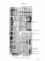
Current settings:
Terminal:
9600 Baud, 8 Bit Word, 1 Stop Bits, No Parity, I1I'R on, RTS off
Modem:
300 Baud, 8 Bit Word, 1 Stop Bits, No Parity, I1I'R on, RTS off
Drive Qty.:
1
Set power-on parameters for:
<T>enninal
<M>odem
<D>isk Drive Quantity
or
<W>rite new parameters to drive A
<E>xit to cP/M
Enter your choice
?
Screen 4-23: Config Utility-Main Menu
4.3.1. TERMINAL & MODEM GROUP
In order for" the terminal or modem to "talk" to the
computer, the baud rate, word length, stop bits, and parity must
be exactly the same for each device. If the terminal parameters
do not match those of the MicroMate, the terminal will display
"garbage" (sequences of characters and symbols that make no
sense) or, because the MicroMate can not understand the data
being entered, it may display nothing at all.
If you are unable to determine the values that your terminal
uses for Word Length, Stop Bi ts, Par i ty, DTR and RTS, it is best
to leave them at the factory settings. Many terminals, modems
and printers work at these settings.
The DTR (Data Terminal Ready) and RTS (Request To Send)
protocol lines are signal lines that the terminal/modem and
computer often use to tell each other when to send data and when
to receive data. Generally these lines are only needed at very
high baud rates.
If not used for Protocol then the state of
these lines is normally set to High (Logical 1).
-40-
MicroMate User's Guide
Section 4
Typing a T or an M ( for Terminal or Modem) followed by
pressing the RETURN key causes the screen to display a table of
the different baud rates that the operating system can support.
Type the letter found in the left column that corresponds to the
baud rate desired. Press RETURN.
-------------------------------------------------<A>
<B>
<C>
<0>
<E>
<F>
<G>
<Ii>
<I>
<J>
<K>
<L>
<M>
<N>
<0>
50
75
110
134.5
150
300
600
1200
1800
2400
3600
4800
7200
9600
19,200
Your Choice ?
---------------- ,---------,---,
Screen 4-24: Config Utility-Possible Baud Rates
The next screen permits changing the control bits. Unless
you are sure of the settings of ALL the control bi ts, answer by
typing an N. After pressing RETURN, the Main Menu reappears; the
new baud rate chosen will now be displayed in the current
settings table for the device first selected.
-------------------,-----
------------,----------
Do you wish to change the Control Bits?
Control bits are:
Word Length
Stop Bits
Parity
Request To Send
Data Tenninal Ready
<Y>es or <N>o
Screen 4-25: Config Utility-Control Bits Prompt
-41-
MicroMate"User's Guide
section 4
Should a Y be typed and the RETURN key pressed at the
"control bits" menu, the prompt will request the word length.
The possible values are displayed on the scree~.
Enter the
selected number and press RETURN. The normal setting is 8.
Word Length
<8>, <7>, <6> or <5>
?
Screen 4-26: Config Utility-Word Length Prompt
The next prompt asks for the number of stop bits~ the
choices are displayed on the screen. Again, choose a number,
enter your selection, and press RETURN.
The normal setting is 1.
Word Length <8>, <7>, <6> or <5>
Stop Bits <1> or <2> ?
?
Screen 4-27: Config Utility-Stop Bits Prompt
Now the prompt on the screen asks whether parity is to be
enabled or disabled.
The normal setting is <D>isable. Type a D
and press RETURN. Should you want Parity enabled, type E instead
of D.
-------------------------------------------------------------------,-----Word Length <8>, <7>, <6> or <5>
Stop Bits <1> or <2> ?
<E>nable or <D>isable Parity ?
?
Screen 4-28: Config Utility-Parity Prompt
-42-
MicroMate User's Guide
section 4
If E is your response, the prompt asks you if parity is to
be <E>ven or <O>dd. Type E or 0 followed by RETURN.
WOrd Length <8>, <7>, <6> or <5> ?
Stop Bits <1> or <2> ?
<E>nable or <D>isable Parity ?
<E>ven or <O>dd parity ?
-------
Screen 4-29: Config Utility-Even/Odd Prompt
If a D is entered, the question about Even and Odd is not
presented.
The last two prompts question whether DTR and RTS are to be
On (High) or Off (Low). Answer with the number that corresponds
to the state desired. Press RETURN. The main menu reappears
after answering all the prompts; the selected new settings are
displayed at the top of the screen under the heading, Current
Settings.
---------------,----------------,
WOrd Length <8>, <7>, <6> or <5> ?
Stop Bits <1> or <2> ?
<E>nable or <D>isable Parity ?
DT.R <O>=off
or <l>=on?
---------._,---------------------
Screen 4-30: Config Utility-DTR Prompt
-----------------------,
Word Length <8>, <7>, <6> or <5> ?
Stop Bits <1> or <2> ?
<E>nable or <D>isable Parity?
DTR <O>=off
or <l>=on?
RTS <O>=off or <l>=on?
,---,----------
,-------------------------------,---Screen 4-31: Config utility-RTS Prompt
-43-
MicroMate User's Guide
Section 4
4.3.2. DRIVE GROUP
The single parameter drive quantity, used by the operating
system, determines the number of disk drives attached to the
MicroMate computer.
Changing this parameter is necessary
whenever disk drives are added to or subtracted from the
MicroMate system: otherwise, the operating system may "hang" if
it tries to access a non-existent drive. When setting this
parameter, ALWAYS include the built-in drive in your count. The
minimum value is 1: the maximum value is 4.
From the Main Menu choose <D>rive Quantity, type a D, and
then press the RETURN key. The Drive Quantity Menu appears. The
choices are 1-4. Type the number of drives desired: be sure,
however, to add the built-in drive A: as number 1.
Disk Drive Quantity Selection
Enter Quantity of Disk Drives available for system use.
Include built in drive.
Mininu:u:n value is <1>
Maxinu:u:n value is <4>
Quantity?
Screen 4-32: Config Utility-Drive Quantity Prompt
-44-
MicroMate User's Guide
Section 4
4.3.3. OTHER MENU OPTIONS
In order to save these new settings onto the diskette,
the
<W>ri te option MUST be used. Type a Wand press RETURN to write
the new parameters to the diskette. DO NOT type an E to <E>xit
from the CONFIG Utility before writing the new settings, unless
you want to abort.
Even if the new parameters are written back onto the
diskette before discovering an error, it is possible to return,
correct the parameter settings, and rewrite the parameters onto
the diskette again.
The new parameters will not take effect until: 1) they are
written to the diskette, and 2) the front panel reset button is
pressed. So, if an incorrect value is inadvertently entered,
written to disk and the Utility exited, you can rerun the Utility
to correct the parameter setting, providing the RESET button has
not been pressed.
-45-
MicroMate User's Guide
Section 4
This Page Blank
-46-
MicroMate User's Guide
Section 4
4.4. CONVERT UTILITY
Command Syntax: CONVERT
Unfortunately there is no standard method used to store
information on a 5 1/4 inch diskette. Some computer manufacturers
use Single Sided, Singl~ Density (SSSD), while others use Single
Sided, Double Density (SSDD), Double Sided, Single Density
(DSSD), or Double Sided, Double Densi ty (DSDD)
5 1/4 inch
diskette storage techniques.
PMC includes a CONVERT Utility that will permit users to
"emulate" several of the different storage techniques that other
manufacturers use.
Anyon-line drive may be converted to a different type.
Once a drive is converted, you may read and write to the other
diskette type; however, the diskette must have been previously
formatted by the machine whose type is being emulated.
The
MicroMate's FORMAT Utility is not capable of formatting any TYPEs
other than PMC-IOl TYPE A and B.
The popular brand name TYPEs that can be converted are found
on the emulation TYPE screen. The actual conversion of the drive
occurs after the TYPE selection has been entered and remains
effective until you press the RESET button or until you perform a
new drive conversion on the same drive.
4.4.1. NORMAL OPERATION
The first screen displayed, after you type CONVERT, provides
a brief introduction.
Press the RETURN key to continue. The
next screen to appear is the drive selection display that
presents the drive letters available for conversion.
Enter the letter of the Drive to be used.
do not enter the
Type
<> brackets.
<"'C> to
abort
Your choice "if <A>, •••••••
Screen 4-33: Convert Utility-Drive Prompt
-47-
MicroMate User's Guide
Section 4
If you press the RETURN key without entering a drive
letter, the Utility aborts! Once the proper drive is selected,
the Emulation TYPE Screen appears.
The "current setting" is
listed on the screen first and is followed by the list of
possible emulations. Select the desire~ emulation TYPE to finish
the conversion process.
Drive A is currently set to Type A
TYPE CCMPUTER
<A> iM::-lOl
<B> iM::-lOl
SIDES DENSITY
2
Double
1
Double
TYPE CGfPUTER
SIDES DENSITY
<N> MicroDecision 1 Double
<z>
Select NEW Type for drive
A
to emulate, <A> thru <Z> or <AC> to abort:
Screen 4-34: Convert
utility~Emulation
TYPE Selection
Once the selection has been made, a confirming prompt is
displayed on the screen.
Drive
A
is now set to Type
A
A>
Screen 4-35: Convert utility-Conversion Confirmation
*
Note
The MicroMate will read
were made only from a
means that, for example,
files, not MS-DOS files,
-48-
*
or write formatted files which
CP/M operating system.
This
with the IBM PC, ONLY CP/M-86
can be read on the MicroMate.
MicroMate User's Guide
Section 4
If you abort the Utility or enter a non-existent TYPE
letter, a different prompt is displayed, which indicates that no
changes were made.
Utility aborted, oorHING done.
A>
Screen 4-36: Convert Utility-Cancellation Confirmation
4.4.2. ADVANCED OPERATION
The advanced command form requires that the user know which
drive is to be converted to which type. No prompts will be
displayed except for a prompt confirming that the conversion has
taken place.
Command Syntax:
CONVERT,drive,type
---------,--_.
A>CONVERT,C,B
Drive C is nCM set to Type B
A>
Screen 4-37: Convert Utility-Conversion Confirmation, Advanced
-49-
MicroMate User's Guide
Section 4
If the drive specified is an invalid drive or the TYPE
letter is out of range, normal prompts are displayed at the point
of error and you are prompted to enter a valid response.
If the
TYPE letter is not valid the utility aborts.
utility aborted, NOrHING done.
A>
Screen 4-38: convert utility-Cancellation Confirmation, Advanced
*
NOTE
*
PMC has tried all of the emulations and found them all
capable of rea~ing and writing to the emulated diskette.
The emulation types, however, are subject to change by
each individual manufacturer; therefore, PMC cannot
guarantee the operation of this utility.
-50-
MicroMate User's Guide
Section 4
4.5. COPYFIL UTILITY
Command Syntax: COPYFIL
This Software Utility permits the user of a single drive
PMC-10l to copy a single file from one diskette to another
diskette. Both diskettes must be of the same TYPE (See section
4.4) •
The file may contain either text or object code and the
maximum file size is 8 Megabytes. This should prove to be more
than adequate for most applications.
Before running this utility make sure that your intended
DESTINATION diskette (the diskette you want the file to be copied
to) is a FORMATTED diskette and contains enough available space
for the intended file.
Use the CP/M command DIR[ SIZE] to
determine the size of the file on the SOURCE diskette'(the
diskette containing the named file to be copied), and then use
the SHOW command, to determine the available space on the
DESTINATION diskette.
When the Utility is first run, an introductory screen
appears. After reading the screen, press RETURN to continue with
the utility.
First the user is prompted for the NAME of the file to copy.
Type in the complete file name followed by a RETURN, but do not
include a drive specification.
e.g. CONVERT.COM. After entering
the name, the user is prompted to insert the SOURCE diskette.
.
Insert SOURCE diskette into drive A:
Press
~
to continue
----------------------------------------Screen 4-39: Copyfil Utility-SOURCE diskette prompt
-51-
MicroMate User's Guide
Section 4
When the RETURN key is pressed, as much of the file as can
fit into the available memory is read from the SOURCE diskette
and stored in memory. Once memory has been filled, the user is
prompted to insert the DESTINATION diskette (the diskette you
want the file to be copied to.) The information stored in RAM is
then written to the DESTINATION diskette.
Insert DESTINATION diskette into drive A:
Press RETURN to continue
Screen 4-40: Copyfil Utility-DESTINATION diskette prompt
If ~he file is larger than the available RAM, then the user
is again . prompted to insert the SOURCE diskette followed by the
DESTINATION diskette.
This procedure will continue until the
entire file has been copied and the user is prompted to re-insert
the SYSTEM diskette.
Note that each prompt is placed in a
different position on the screen to help the user quickly
identify the operation required.
Insert SYSTEM diskette into drive A:
Press RETURN to continue
Screen 4-41: Copyfil Utility-SYSTEM diskette prompt
If the DESTINATION diskette already contains a file by the
same name, the user is given the option of aborting the utility
or erasing the existing copy of the file.
Type control C to
abort.
There is no advanced command form for this utility.
-52-
MicroMate User's Guide
Section 4
4.6. SYSTEST UTILITY
Command Syntax: SYSTEST
Before this Software Utility can be used, a special SYSTEST
diskette must be made. Use the BACKUP Utility to copy a CP/M 3.0
SYSTEM diskette. Label the copy diskette SYSTEM TEST. From this
diskette, erase the two files HELP.COM and HELP.HLP to obtain
needed working room.
To do this type ERA HELP.COM and press
<RETURN>, when the A> prompt reappears type ERA HELP.HLP and
press <RETURN>.
Next, use T/Maker to create a file named PROFILE.SUB. This
file will automatically load and run the SYSTEST program when the
MicroMate is powered on. At the A> prompt, remove the SYSTEM
TEST diskette and insert the T/MAKER diskette.
Type TMAKER and
press the <RETURN> key. At the WHAT NEXT? prompt, type RESET and
press <RETURN>. Remove the T/MAKER diskette and reinsert the
SYSTEM TEST diskette.
At the WHAT NEXT? prompt, type CREATE PROFILE.SUB EDIT and
press <RETURN>. When you are in the editor (blank screen with
the cursor in the upper left corner), type the word SYSTEST and
then press the <RETURN> key. The cursor should be in the left
most column on the line below the word SYSTEST. Exit the editor
by typing a control Q (hold the CTRL key down and simultaneously
press the the Q key). At the WHAT NEXT? prompt type SAVE and
press <RETURN>, to write the newly created PROFILE.SUB file to
the SYSTEST diskette.
To test the integrity of the hardware, disconnect the
terminal end of the RS-232 cable from the terminal and plug it
into the connector labelled "MODEM II on the rear panel of the
MicroMate. If this step is skipped, all tests except for the
DART test, will be performed.
Insert the special SYSTEM TEST diskette into the A: drive
and press the reset button. This initiates a continuously-running
loop that will keep the drive activity light blinking until an
error occurs.
The disk drive, serial ports, all 128K bytes of memory, and
all major IC chips are tested.
-53-
MicroMate User's Guide
Section 4
If a parallel printer is attached, th~ name of each segment
of the test, as it begins, is printed. The tests function as
normal even if no printer is attached; however, it is difficult
to tell which test, if any, fails. There are four tests: Disk,
Seek, Dart, and RAM.
Disk
Seek
Dart
RAM
test:
test:
test:
test:
checks the read/write capabilities of the drive.
checks the stepping capability .of the drive.
checks the operation of the serial ports.
test all l28K bytes of memory.
This is not a diagnostics test, but a functionality test.
If an error occurs during any test, an error message is printed
out .next to the identified test.
For complete details on the error messages, see Appendix B.
-54-
Section 5
MicroMate User's Guide
5. DEVIATIONS FROM CP/M PLUS
5.1. DOCUMENTATION
MicroMate
User's Guide
CP/M
User's Guide
1.1
1.4
Read Section 2 instead.
BACKUP is a faster and easier method.
Section 4.2.
3.3.1
3.5
Ignore non-banked sections.
The DEVICE command and Logical devices are
supported.
See Section 5.2.
5.COPYSYS
5.DEVICE
COPYSYS can only be used with TYPE A drives.
See Section 5.2 for physical devices.
See Section 5.5 regarding Protocols.
CP/M
Programmer's Guide
1.1
1.5
1.6.1
See
MicroMate·
User's Guide
Ignore non-banked sections.
See Section 6.1 for memory maps.
The CCP is stored on the system cylinder.
See Section 6.4.
See Section 6.5 for Cold Start Operation.
*
NOTE
*
INFORMATION CONTAINED IN THE PROGRAMMER'S GUIDE IS
CONSIDERED TECHNICAL INFORMATION AND IS INTENDED FOR THE
ADVANCED USER.
-55-
MicroMate User's Guide
CP/M
System" Guide
1.5
1.9
Section 5
MicroMate
User's Guide
Ignore non-banked sections.
See Section 6.1 for memory maps~
The MicroMateuses a ROM loader. Refer to
Section 6.5.
2.5
2.6
2.7
MULTIO is not implemented.
XMOVE is implemented.
Clock is supported.
See Section 5.4.
3.4
FLUSH is not implemented.
4.1
Refer to Section
differences.
4.7.3
TYPE is used." See Section 6.3.
5.1
5.2
Type the GENCPM.DAT file for default values.
The CCP is stored on the system cylinder.
See Section 6.4
Apndx.A
Apndx.B
Apndx.E-J
Media flag not implemented.
Ignore.
Ignore <See the source code files)
*
NOTE
5.3
for
file
*
INFORMATION CONTAINED IN THE SYSTEM GUIDE IS CONSIDERED
TECHNICAL INFORMATION AND IS INTENDED FOR THE ADVANCED
USER.
-56-
name
MicroMate User's Guide
section 5
5.2. DEVICES
Under CP/M 3.0, Logical devices are implemented for the
following physical devices;
TERMNL -Serial communication
to a terminal (TERMINAL connector)
MODEM -Serial communication
to a modem
(MODEM
connector)
CENTRN -Parallel communication to a printer (PRINTER connector)
5.2.1. DEFAULT POWER-ON PARAMETERS
Baud
Rate
Word
Length
Stop
Bits
Parity
DTR
RTS
ELECTRIC WEBSTER MASTER diskette
Terminal
Modem
Drive Qty.
19200
300
1
1
Disabled
Disabled
On
On
On
On
1
1
Disabled
Disabled
On
On
On
On
1
1
Disabled
Disabled
On
On
On
On
8
8
1
Disabled
Disabled
On
On
On
On
8
8
1
1
Disabled
Disabled
On
On
On
On
1
Disabled
On
On
8
8
1
SYSTEM MASTER diskette
Terminal
Modem
Drive Qty.
9600
300
8
8
1
CBASIC MASTER diskette
Terminal
Modem
Drive Qty.
1200
300
8
8
1
SOURCE MASTER diskette
Terminal
Modem
Drive Qty.
300
300
1
1
T/MAKER diskette
Terminal
Modem
Drive Qty.
110
300
1
QUME QVT-I02 Terminal
9600
8
-57-
MicroMate User's Guide
Section 5
5.3. FILE NAME DIFFERENCES
BIOSKRNL.ASM integrated into BIOS3.ASM
CHARIO.ASM
integrated into BIOS3.ASM
MOVE.ASM
integrated into BIOS3.ASM
BOOT.ASM
,integrated into BIOS3.ASM
DRVTBL'.ASM
integrated into BIOS3.ASM
DISKIO.ASM
FD1797SD.ASM
PORTS.LIB
PORTS.LIB
MODEBAUD.LIB
MODEBAUD.LIB
CPM3.LIB
CPM3.LIB
PMCEQU.LIB
LDRBIOS.ASM
5.4. REAL TIME CLOCK
The Real Time Clock is implemented using the Zilog CTC chip
and is interrupt driven.
Therefore, operations involving
considerable disk accesses cause the clock to lose time.
If the front panel RESET button is pressed or the MicroMate
system is powered-off, the Real Time Clock is reset to 00:00:00.
The DATE SET command (See the CP/M User's Guide) must be used to
set the time again and start the clock running.
-58-
MicroMate User's Guide
Section 5
5.5. PROTOCOLS
XON/XOFF protocol is supported and can easily be turned ON
or OFF by using the DEVICE Utility (See your CP/M User's guide.)
Although our extended Bios for the MicroMate can support
protocols, neither DSR nor CTS protocols are implemented at time
of shipment.
In order to implement any protocols other than
XON/XOFF, the PMCEQU.LIB file must be changed and the Bios must
be reassembled. You will not be able to implement a protocol,
other than XON/OFF, by just using a utility •
. If you modify and reassemble· the Bios to implement DSR or
CTS protocol, you do so at your own risk. Personal Micro
Computers, Inc. will not support any changes a user makes to the
source code, and cannot assume responsibility if a user modifies
the source code and it happens not to work as expected.
To implement a protocol, use the T/Maker editor to change
the "false" equate to "true" for the protocol of your choice.
This equate is found at the top of the PMCEQU.LIB file which is
on the CP/M 3.0 SOURCE diskette. First, use the BACKUP utility
to copy a SOURCE diskette and label this copy "NEW PROTOCOL
SOURCE".
At the A> prompt, insert the T/MAKER diskette, type TMAKER
and press the <RETURN> key.
At the WHAT NEXT? prompt, type
RESET and press <RETURN>. Remove the T/MAKER diskette and insert
the NEW PROTOCOL SOURCE diskette. At the WHAT NEXT? prompt, type
GET PMCEQU.LIB EDIT and press <RETURN>.
When you are in the
editor you will see the beginning of the PMCEQU.LIB file
displayed on the screen. Move the cursor down through the file
using the down arrow key (Qume terminal) or by typing control J
(other terminal) until you see these lines:
CTS$protocol equ
DSR$protocol equ
false
false
Select which protocol you wish to implement and move the
cursor so that it is on that line. In our example we will
implement CTS protocol. Now, move the cursor until it is over
the "f" in the word false by using the right arrow key or typing
control L. Type the word TRUE and press the space bar once to
remove the remaining "e" from the word "false". After you have.
edited the equates, the code should read like this:
CTS$protocol equ
DSR$protocol equ
true
false
-59-
MicroMate User's Guide
Section 5
Now exit the editor by typing control Q. At the WHAT NEXT?
prompt, type SAVE and press <RETURN> to save the modified equate
file back to disk.
After saving PMCEQU.LIB back to disk, you must reassemble
the Bios. A submit file namedBIOS.SUB may be used to do this
automatically. At the A> prompt type SOBMIT BIOS and press
RETURN. The submit file will reassemble the Bios and link it to
the operating system files to create a file called CPM3.SYS.
Transfer this new CPM3.SYS to a NEW diskette. Make sure you run
COPYSYS (See CP/M User's Guide) to transfer the Boot Loader to
the boot cylinder of the new diskette.
Before the new
protocol(s) can take effect, the system must be booted from the
new diskette that contains the new version of CPM3.SYS.
Once implemented, the only way to disable the protocol(s) is
to change the equate(s) back to false and reassemble the Bios OR
re-boot the system using a diskette that has a non-DSR and/or CTS
protocol version of CPM3.SYS.Be sure to mark the diskette
containing the new version of CPM3.SYS to indicate that this
version supports the protocol(s).
*
NOTE
*
Enabling a protocol will affect both the terminal output as
well as the modem output.
There is no way to enable
protocol on a single output.
-60-
MicroMate User's Guide
Section 5
5.6. PARITY
The terminal communicates with the PMC-IOI by sending and
receiving alpha characters and special codes.
Each character or
code is called an ASCII byte and is made up of eight individual
bits. The bits are counted from right to left beginning with bit
o and ending with bit 7.
I ASCII Byte:
Bit
7
6
5
4
3
2
I
o
To add to the confusion, Bit 0 is sometimes called the 1st
bit as is Bit 7 sometimes called the 8th bit.
Generally the terminal only uses 7 bit (bits 0 thru 6)
characters and codes. The 8th bit (bit 7) is used as a parity
bit.
The CP/M 3.0 standard states that the eighth bit (Parity)
not be stripped (masked) from both the Console Input (Terminal)
and Auxiliary Input (Modem) characters before they are passed to
the operating system.
Some communication programs, that use the Bios input
routines, require that 8 bit characters and codes be used. As
shipped from the factory the eighth bit is not stripped (parity
is not masked) from the input character.
Should the user desire
to deviate from the CP/M 3.0 standard and mask the 8th bit from
codes to be received, the PMCEQU.LIB file must be modified and
the Bios must be reassembled.
Most commercially available communication programs do not
use the Bios Input/Output routines and no Bios changes are
required to use them. Before making the Bios modification, test
your program.
If you use PIP to transfer .COM files from one machine to
another, you should not make this Bios modification.
-61-
MicroMate User's Guide
Section 5
If you modify and reassemble the Bios to enable parity
masking, you do so at your own risk. Personal Micro Computers,
Inc. will not support any changes a user makes to the source
code, and cannot assume responsibility if a user modifies the
source code and it happens not to work as expected.
To enable parity masking, use the T/Maker editor to change
the "false" equate to "true" for the parity mask.
This equate is
found at the top of the PMCEQU.LIB file which is on the CP/M 3.0
SOURCE diskette.
First, use the BACKUP utility to copy a SOURCE
diskette and label this copy "PARITY MASK ENABLED SOURCE".
At the A> prompt, insert the T/MAKER diskette, type TMAKER
and.press the <RETURN> key. At the WHAT NEXT? prompt, type
RESET and press <RETURN>. Remove the T/MAKER diskette and insert
the PARITY MASK ENABLED SOURCE diskette.
At the WHAT NEXT?
prompt, type GET PMCEQU.LIB EDIT and press <RETURN>.
When you
are in the editor you will see the beginning of the PMCEQU.LIB
file displayed on the screen. Move the cursor down through the
file using the down arrow key (Qume terminal) or by typing
control J (other terminal) until you see this line:
Parity$mask equ
false
Move the cursor so that it is on this line. Now, move the
cursor until it is over the "f" in the word false by using the
right arrow key or typing control L.
Type the word TRUE and
press the space bar once to remove the remaining "e" from the
word "false". After you have edited the equate, the code should
read like this:
Parity$mask equ
true
Now exit the editor by typing control Q. At the WHAT NEXT?
prompt type SAVE and press <RETURN> to save the modified equate
file back to disk.
After saving PMCEQU.LIB back to disk, you must reassemble
the Bios. A submit file named BIOS.SUB may be used to do this
automatically. At the A> prompt type SUBMIT BIOS and press
RETURN. The submit file will reassemble the Bios and link it to
the operating system files to create a file called CPM3.SYS.
Transfer this new CPM3.SYS to a NEW diskette. Make sure yo.u run
COPYSYS (See CP/M User's Guide) to transfer the Boot Loader to
the boot cylinder of the new diskette. Before the parity masking
is enabled, the system must be booted from the new diskette that
contains the new version of CPM3.SYS.
-62-
MicroMate User's Guide
Section 5
Once implemented, the only way to disable parity masking is
to change the equate back to false and reassemble the Bios OR reboot the system using a diskette that does not have a parity
masking version of CPM3.SYS.Be sure to mark the diskette
containing the new version of CPM3.SYS to indicate that this
version does mask the parity bit.
*
NOTE
*
Enabling parity masking will affect both the terminal input
as well as the modem input.
There is no way to enable
parity masking on a single input.
-63-
Section 5
MicroMate User's Guide
This Page Blank
-64-
MicroMate User's Guide
Section 6
6. TECBRICAL REFERENCE
6.1. BANK SWITCHING
Bank switching is done by the. operating system and is
transparent to the users' programs.
Individual programs MAY NOT
perform_bank switching, as all banked memory is currently managed
by CP1M PLUS.
The bank switching operation uses a "WINDOW" located between
4000H and BFFFH. This means that the other banks are switched
into and out of this memory space.
The physical location of each logical bank is listed below:
NAME
--------------
Logical Bank 0
Logical Bank 1
Logical Bank 2
ADDRESS
LOCATION
-----------------------------------
4000H-BFFFH
0000H-7FFFH
8000H-FFFFH
First 64K of memory
Second 64K of memory
Second 64K of memory
To select Logical Bank 0: Reset all bits of the bank select port.
To select Logical Bank 1: Set bit 7 of the bank select port; bits
0,2,3,4,5,6 may be set or reset.
To select Logical Bank 2: Set bi ts 1 and 7 of the bank select
port; bits 0,2,3,4,5,6, may be set or
reset.
*
NOTE
*
Notice that the CCP is stored in Logical Bank 3; this
corresponqs to physical Bank 2 with the zero bit set.
Also, notice that bank numbers 7 and 3 are used for
input to the GENCPM program. This is because we have
found that GENCPM will not allocate the proper buffers
if even bank numbers are used with our particular memory
setup. Therefore, Bank numbers 3 and 7 are used, but
they only set Bank 2 because the other bits are ignored.
DRI has been made aware of this situation.
-65-
MicroMate User's Guide
Section 6
MEMORY MAPS
Physical
Address
FFFFh
Logical
Address
+-----~-------------------+ FFFFh
Resident Bros
FBOOh
Resident BOOS
FSOOh
+-------------------------+
Banked BIOS
-------------------------
COOOh --------------------BSOOh
Banked BOOS
-------------------------
8800h
Bank 0
Hashed Directory"Tables
LRU Directory Buffers
OOOOh
+-------------------------+
4000h ---------------------
+-------------------------+
OOOOh
Fig. 6-1: Memory Map-First 64K
-66-
MicroMate User's Guide
Physical
Address
IFFFFh
+-------------------------+
Section 6
Logical.
Address
COOOh ---------------------
Hashed Directory Tables
LRU Data Buffers
------------------------Copy of CCP f/Warm start
8DOOh
Bank 2
8000h
Hashed Directory Tables
LRU Data Buffers
18000h
+-------------------------+
4000h ---------------------
17FFFh
+-------------------------+
COOOh ---------------------
TPA
lOOOOh
+-------------------------+
Bank 1
4000h ---------------------
Fig. 6-2: Memory Map-Second 64K
-67-
MicroM~te
User's Guide
Section 6
6.2. TYPE A DISKETTES
6.2.1. PHYSICAL SPECIFICATIONS: TYPE A PMC-lOl DISKETTE
Formatted capacity:
Sides:
Cylinders per disk:
Tracks per side:
Sectors per cylinder:
Sectors per track:
Bytes per sector:
Sector skew factor:
Sector translation table:
Directory entries:
Reserved tracks:
Block size:
400K
2
40
40
10
5
1024
o
1, 2, 3, 4, 5, 6, 7, 8, 9, 10
128
1
2048
6.2.2. DPB: TYPE A PMC-lOl DISKETTE
dpb1:
dw
db
db
db
dw
dw
db
db
dw
dw
db
db
db
-68-
80
4
15
1
194
127
192
0
32
1
3
7
'A'
SPT
BSH
BLM
; EXM
, DSM
, DRM
; ALO
, ALI
; CKS
, OFF
, PSH
; PHM
; TYP
;
;
·
·
·
·
·
128 BYTE RECORDS PER TRACK
BLOCK SHIFT
BLOCK MASK
EXTENT MASK
MAX BLOCK QUANTITY-l
MAX DIR ENTRIES-l
ALLOCATION VECTOR LSB
MSB
CHECKSUM VECTOR
TRACKS OFFSET
PHYSICAL SECTOR SIZE SHIFT
PHYSICAL SECTOR SIZE SHIFT
PMC extension
MicroMate User's Guide
Section 6
6.2.3. FORMATTING INFORMATION: TYPE A PMC-IOI DISKETTE
Name
Gap 5
C2
Idx Adr Mrk
Gap 1
Byte
Qty.
4E
00
F6
FC
4E
80
12
3
1
50
repeat this block 5 times per track.
Al
Data Adr Mrk
Data
eRC
Gap 3
3
F7
4E
00
F5
FB
E5
F7
4E
12
3
1
1
1
1
1
1
22
12
3
1
1024
1
85
Gap 4
4E
250
Al
Data Adr Mrk
Track
Head
Sector
Sector Len
CRC
Gap 2
00
F5
FE
?
?
?
(range 0-39)
(range 0-1)
(range 1-5)
(generates 2 bytes)
(generates 2 bytes)
-69-
Section 6
MicroMate User's Guide
6.3. TYPE BYTE
This 8 bit coded byte is used by f$read & f$write to
determine the Density, Sides and Head Switching technique of the
drive currently selected. Each physical drive must have a type
byte. The CONVERT Utility changes this byte along with the DPB
and Translation table to emulate other Drive types. MicroMate
TYPE A type byte is OOH which means:
DsDd
Head Switch on sector count
Switch on sector number 6
6.3.1. "TYPE" byte used in DPH
Bit Number
7 6 54$ 3 210
I I
? ?
+=+- OO=DsDd
Ol=DsSd
10=SsDd
11=SsSd
Type
? ? x x
+=+---- 00= Switch on Sector,
10= Switch on Even/Odd,
? ? ??
Ol=Switch on Track
ll=Switch on Odd/Even
0 0 0 x
+=+=+=+~---------
OOOO=Sct 6 - 1111=Sct 21
(If Sector switching)
I I
??
0 lOx
+=+---------- OO=Switch on Track 34,
10=Switch on Track 41,
01=36,
11=81
(If Track
Switching)
? x x
0 lOx
+-------------- O=Side 0 first, l=Side 1 first
? x x x
0 lOx
+---------------- Spare
(?=value in question1 x=can be either 0 or 11 @=unknown value)
Fig. 6-3: TYPE Byte-Bit Designations
-70-
MicroMate User's Guide
Section 6
6.3.2. SAMPLE Disk Parameter Header
xdph@
dw
dw
dw
dw
db
db
f$write
f$read
f$login
f$init
@
?
dph@
dw
Trans@
db 0,0,0,0,0,0,0,0,0
db
dpb@
dw
dw
ck@
al@
dw
dw
OFFFEh
OFFFEh
dw
dw
OFFFEh
db
°
°
;*Extended DPH*
Pointer to Write routine
;
Pointer to Read routine
;
Pointer to Login routine
;
Pointer to Init routine
Actual drive select code
;
UNIT
;
TYPE
Drive type
;*DPH*
XLT
Translation table
;
-0j
BOOS scratch area
MF
Media Flag
DPB
Disk Parameter Block
;
;
CSV
Checksum Vector
ALV
Allocation Vector
DIRBCB Directory BCB Vector
DTABCB Data BCB Vector
j
HASH
Hash Table Vector
HBANK Hash Bank
;
6.3.3. "TYP" byte used in DPB
This byte is only used by the CONVERT Utility to display the
current TYPE setting of the selected drive.
The byte stored here
must be in ASCII. The value range is 'A' thru 'Z'.
6.3.4. SAMPLE Disk Parameter Block
dpb@:
dw
db
db
db
dw
dw
db
db
dw
dw
db
db
db
@@@@
@@
@@
@@
@@@@
@@@@
@@
@@
DRM+l/4
@@@@
@@
@@
' ?'
;
j.
;
;
,·
··,,
;
;
·,;
,·
SPT
BSH
BLM
EXM
DSM
DRM
ALO
ALI
CKS
OFF
PSH
PHM
TYP
128 BYTE RECORDS PER TRACK
BLOCK SHIFT
BLOCK MASK
EXTENT MASK
MAX BLOCK QUANTITY-l
MAX DIR ENTRIES-l
ALLOCATION VECTOR LSB
MSB
CHECKSUM VECTOR
TRACKS OFFSET
PHYSICAL SECTOR SIZE SHIFT
PHYSICAL SECTOR SIZE SHIFT
PMC extension
-71-
MicroMate User's Guide
section 6
6.4. BOOT CYLINDER
The physical layout of data on the boot cylinder is shown
below:
Cylinder 0:
Physical
sector
#
Track 0
Side 0
Sector 1
1
1
2
3
4
5
Track 0
Side 1
Sector 1
2
3
4
5
-72-
Segment
Length
l28bytes
l28bytes
768bytes
1024bytes
1024bytes
1024bytes
1024bytes
Disk Load info
Serial Init info
empty
CPMLDR(Max length
CPMLDR
800h)
empty
empty
1024bytes
1024bytes
1024bytes
1024bytes
1024bytes
CCP.COM(Max Length
CCP.COM
EOOh)
CCP.COM
CCP.COM
empty
MicroMate User's Guide
Section 6
6.4.1. TRACK 0, SECTOR 1 - Disk Load Information Segment
All values are in HEX
BYTE#
00
01
02
Exec Bank
Exec adr LSB
MSB
09
Load #1
BANK
Load adr LSB
MSB
Side select
Trk
Sct
Qty
OA
OB
OC
OD
OE
OF
10
Load #2
BANK
Load adr LSB
MSB
Side select
Trk
Sct
Qty
03
04
05
06
07
08
16
17
Load #3
BANK
Load adr LSB
MSB
Side select
Trk
Sct
Qty
18
19
lA
IB
lC
lD
IE
Load #4
BANK
Load adr LSB
MSB
Side select
Trk
Sct
Qty
11
12
13
14
15
Execution will begin in this Bank
Execution will begin at this address
OO=bnkO, 80=bnkl, 82=bnk2, FF=no more
Loading will begin at this address
OO=side 0, 02=side 1
Track number to load from
Starting Sector number to load
Quantity of physical sectors to load
OO=bnkO, 80=bnkl, 82=bnk2, FF=no more
Loading will begin at this address
OO=side 0, 02=side 1
Track number to load from
Starting Sector number to load
Quantity of physical sectors to load
OO=bnkO, 80=bnkl, 82=bnk2, FF=no more
Loading will begin at this address
OO=side 0, 02=side 1
Track number to load from
Starting Sector number to load
Quantity of physical sectors to load
OO=bnkO, 80=bnkl, 82=bnk2, FF=no more
Loading will begin at this address
OO=side 0, 02=side 1
Track number to load from
Starting Sector number to load
Quantity of physical sectors to load
etc.
One entire 128 byte segment is reserved for load
information.
-73-
MicroMate User's Guide
6.4.2. TRACK 0, SECTOR
section 6
1 - Serial Initialization Segment
All values are in HEX
BYTE#
+80
. Power-on baud rate byte. High Nibble is A channel, Low
nibble is B channel. Default = E6H.
+81
Quantity of Disk Drives attached to system (include built
in drive). Default = OlH.
+90
Serial channel A (TERMINAL) initialization data.
Contains register number followed by the data byte for
Registers 00,01,03,04,05 ONLY. Default = OOH, l8H,.OlH,
oOH, 03 H, COH, 04H, 44H, 05H, EAH.
+AO
Serial channel B (MODEM) initialization data. Contains
register number followed by the data byte for registers
00,01,02,03,04,05. Default = OOH, l8H, OlH, OOH, 02H,
70H, 03H, COH, 04H, 44H, 05H, EAH.
+BO through +FF are not used.
-74-
MicroMate User's Guide
Section 6
6.5. BOOT SEQUENCE
6.5.1. ROM
At power-on the Phantom ROM begins execution at Address
OOaOH.
The ROM first Disables Interrupts and then loads in Sector
1, Track 0, Side O. The information transferred from this sector
is essential to the system setup as it contains the power-on
parameters for booting the operating system.
The information is
used as follows:
1)
2)
2)
3)
Set the baud rates of both serial channels.
Initialize the DART.
The drive quantity is stored in the I register.
Determine the bank, load address, side, track
starting sector number, and sector quantity for
the first load procedure.
4) Load the segment as specified.
5) Determine if any more load segments are specified.
If so, go back to step 4 until all segments are
loaded into memory.
6) Determine the execution address and bank. Disable
interrupts, phantom out the ROM and pass control
to the execution address.
The first segment that is loaded contains the CPMLDR and it
is placed in bank a at location 3000H.
The second segment
contains the CCP and is loaded int6 bank 2 at location 8aaOH.
Execution begins at location 3000H in Bank a.
6.5.2. CPMLDR
The minimal Bios portion of the CPMLDR contains only the
disk read routine READ:,· and the CONOUT: routine. The CPM3.SYS
file is loaded into the appropriate banks of memory before
control is passed to the Bios BOOT: routine.
-75-
MicroMate User's Guide
Section 6
6.5.3. BIOS BOOT
The Bios BOOT: routine resides in the space used by the ALL
and CKS vectors and will be overlayed when the first Disk I/O
occurs. The following functions are performed:
1)
2)
3)
4)
5)
6)
7)
8)
9)
10)
11)
12)
13)
14)
15)
-76-
Retrieve the Drive Quantity byte from I register
Adjust Drive table to match drive quantities
Retrieve the baud rate entries from BRG
Set baud rates in CTBL
Set CON:=TERMNL
Set AUX:=MODEM
Set LST:=CENTRN
Load I register withMSB of the Interrupt Vector Table
Reset CTC channels
Send LSB of the IVT to the CTC
Set interrupt mode to 1M2
Print Sign On message
Set BIOS and BDOS entry points in page 0
Copy CCP from bank 2 to TPA in bank 1
Pass control to the CCP
MicroMate User's Guide
Section 6
6.6. MODEM PORT SPECIFICATIONS
The following information is for those MicroMate users who
wish to implement a software communications package in connection
with a modem to electronically transfer files and programs from
another computer to a MicroMate. The B channel of a Zilog DART
chip (Dual Asynchronous Receiver Transmitter) is used in the
MicroMate to interface a modem to the CPu. Consult a Zilog Data
Book for more detailed information on the DART chip.
6.6.1. PORT VALUES
B Channel (Modem) Port Values:
Data Port
Command Port
Status Port
89 Hex
8B Hex
8B Hex
6.6.2. BIT POSITIONS
To test for RDA (Received Data Available) test bit 0 of the
Status Port.
If this bit is set (Logical 1), then a character
has been received by the DART.
To test for TBE (Transmit Buffer Empty) test bit 2 of the
Status Port.
If this bit is set (Logical 1), then the DART
transmit buffer is empty and a character may be loaded and
transmitted.
To check CTS, DCD or RI:
1)
output 00 Hex to command port
2)
output 10 Hex to command port
3)
input from the Status port
4)
(if the bit is
test bit 3 for DCD status
set {I} the line
test bit 4 for RI status
is active)
test bit 5 for CTS status
To set RTS or DTR:
1)
output 05
2)
output E8
output 6A
output EA
output 68
Hex
Hex
Hex
Hex
Hex
to
to
to
to
to
command
command
command
command
command
port
port
port
port
port
to
to
to
to
enable DTR
enable RTS
enable DTR&RTS
disable DTR&RTS
-77-
MicroMate User's Guide
section 6
6.6.3. SETTING BAUD RATES
Use port 93 Hex to set the baud rates. The High Nibble
(bits 7,6,5,4) control the A channel (Terminal port) baud rate.
The Low Nibble (bits 3,2,1,0) control the B channel (Modem port)
baud rate.
Specific Baud Rates are set by outputting the following data
to the Baud Rate port (93H):
·Baud Rate
50
75
110
134.5
150
300
600
1200
1800
2000
2400
3600
4800
7200
9600
19,200
Example:
Data
o Hex
1
2
3
4
5
6
7
8
9
A
B
C
D
E
F Hex
To set the A channel (terminal port) to 9600 baud
and the B channel (modem port) to 300 baud,
output E5 Hex to port 93 Hex.
The Modem port connector is wired to the DART as follows;
DART
Transmit Data
Receive Data
Request To Send
Clear To Send
Data Carrier Detect
Data Terminal Ready
Ring Indicator
-78-
Connector Pin
(Tx Data)
(Rx Data)
(RTS)
.( CTS)
(DCD)
(DTR)
(RI)
2
3
4
5
8
20
22
APPENDIX
A
A. ,CABLES & CONNECTORS
A.I. RS-232 TERMINAL CABLE
MicroMate
DB-25
male
connector
Terminal
9 ,conductor
round
cable
DB-25
male
connector
•
1
I
,
-~
Ji2l;,~r-'----=:rc::.~iiZ.:IIII:~_ _....:::IIE_4\ ~.
...
Signal
NaIre
Fig. A-I: standard RS-232 Terminal Cable.
Pin
#
Pin
#
Ground
Rx data
Tx data
I
2
3
-------------------------------------------------------------------
1
2
CTS
4
----------------------------------
3
RTS
5
---------------------------------- 4
DTR
6
Ground
OCD
DSR
7
8
20
----------------------------------
5
---------------------------------- 6
---------------------------------- 7
----------------------------------
8
---------------------------------- 20
Signal
Nane
Ground
Tx data
Rx data
RTS
CTS
DSR
Ground
OCD
orR
".-'-.-- ...~~,
Signal
Direction
<--->
<-->
-->
->
<--
A-79
APPENDIX
A
A.2. RS-232 MODEM CABLE
MicroMate
DB-25
male
connector
a_
Modem
9 conductor
round
cable
DB-25
male
connector
~p~~~~d~~~~~~~~
'., >,.
..
-:~--;Signal
II' '
Fig. A-2: Standard RS-232 Modem Cable.
Pin
Pin
#
#
Ground
data
data
RTS
CTS
DSR
Ground
DCD
1
2
----------------------------------
3
-------------------------------------------------------------------
1
2
3
4
OrR
A-aD
4
5
-----------------~----~-----------
Signal
Name
Ground
Tx data
Rx data
<-<-<--
5
6
CTS
DSR
7
----------------------------------
7
GROUND
---------------------------------- 20
--)
--)
----------------------------------
---------------------------------- a
Signal
Direction
·RTS
----------------------------------
20
--1
'--"-.,
6
a
•..
. ' \ . . s , " ,',. ",~. '
Narre
Tx
Rx
•
DCD
<--
orR
--)
AP'PENDIX
A
A.3. RS-232 PRINTER CABLE
MicroMate
OB-25
male
connector
Printer
9 conductor
round
cable
DB-25
male
connector'
I -~P____-"iiiiiiiiiiiiiiiiiiiiliil"_ _ _ _ _iiii"
.~)
-1~]
~/.
~
Fig. A-3: ~Null-Modem" RS-232 Printer Cable.
Signal
---if-,
Pin
Pin
Name
#
#
Narre
Ground
Tx data
Rx data
1
2
3
4
-------------------------------------------------------------------------------------------------------------------------------------
1
3
2
5
Ground
Rx data
Tx data
--)
CTS"
--)
5
6
---------------------------------- 4
---------------------------------- 20
RTS
<-<--
7
---------------------------------- 7
20
6
RTS
ern
OSR
Ground
OCO
DTR
a
no connection
----------------------------------
Signal
D1'R
•
Signal
Direction
<--
Ground
DSR
--)
Note: RTS andOTR leaving the printer at pins 4 and 20
on the cable should be seen as low enabling signals by
the Micromate at pins 5 and 6 on its end of the cable.
A-al
APPENDIX
A
A.4. RS-232 CONNECTOR
viewing "pin" end (not "cable" end)
Pin#
Pin#
14
f
15
",
16
17
!"'.~
18
1 C
..L.;
20
21
22
23
24
25
Fig. A-4: Male RS-232 Connector
A-82
APPENDIX
A
A.5. PARALLEL PRINTER CABLE
34 Pin
edge
connector
34 conductor
flat
cable
Centronics
D
Cable
Signal
NaIre
Pin
#
Strobe
1 ---------------------------------Ground
2' ---------------------------------Data 0
3 ---------------------------------Ground
4 ---------------------------------Data 1
5 ---------------------------------Ground
6 ---------------------------------Data 2
7 ~--------------------------------Ground
8 ~--------------------------------Data 3
9 ------------.---------------------Ground
10 ---------------------------------Data 4
11 ~--------------------------------Ground
12 ------------------~--------------Data 5 · 1 3 ---------------------------------Ground
14 ---------------------------------Data 6
15 ------~--------------------------Ground
16 -----~---------------------------Data 7
17 ---------------------------------Ground
18 ---------------------------------No connect 19 --------------------------------~Ground
20 ---------------------------------Busy
21 -------------------------------"-Ground
22 -----------------------~---------Paper Out' 23 ---------------------------------Ground
24 ---------------------------------Select
25 -----~---------------------------No connect 26
---~-----------------------------No connect 27 '-----------------.---------------Fault
28 ---------------------------------No connect 29 ------~~----------------------~--No connect 30
----------~-~--------~-----------No connect 31 ---------------------------------No connect 32
---------------------------------No connect 33-34---------------------------------
Pin
.#
Signal
Direction
1
--)
19
2
--)
20
3
--)
21
4
--)
22
5
--)
23
6
--)
24
7
--)
25
8
--)
26
9
--)
27 ~ . , )
10, (A"C f\
28
11
<-29
12
<-30
13
<-31
14 '
32
<-15
33
16
34
17,35,18.,36
A-83
APPENDIX
A
A.6. ADD-ON DISK DRIVE CABLE
34 Pin
edge
connector
34 conductor .
flat
cable
34 pin
edge
connector
34 pin
a:1ge
connector
34 pin
a:1ge
connector
Pin
#
Pin
#
Fig. A-6: Disk Drive cable
Signal
NaIre
Pin
#
Ground
No connect
Ground
No connect
Ground
Drv Sel 3
Ground
Index
Ground
Drv Se1 0
Ground
Drv Sel 1
Ground
Drv Sel 2
Ground
Motor On
Ground
Direction
Ground
Step
Ground
Write Data
Ground
Write Gate
Ground
Track 0
Ground
Wrt Prot
Ground
Read Data
Ground
Head 2
Ground
No connect
1
2
3
4
5
6
7
8
9
10
11
12
13
14
15
16
17
18
19
20
21
22
23
24
25
26
27
28
29
30
31
32
33
34
A-84
Pin
#
--------------------- 1
--------------------- 32
--------------------- 4
--------------------- 5
--------------------- 6
----------------------------------------- 87
--------------------- 9
----------------------------------------- 10
11
-----------------12
--------------------- 13
--------------------- 14
--------------------- 15
--------------------- 16
--------------------- 17
--------------------- 18
--------------------- 19
----------------------------------------- 20
--------------------- 21
--------------------- 22
--------------------- 23
24
-------------------- 25
--------------------- 26
----------------------------------------- 27
28
-------------------------------------- 29
--------------------- 30
--------------------- 31
32
--------------------- 33
--------------------- 34
---------------------
----------------------------------------------------------------
-------------------------------------
----------------------------------------------------------------------------------------------------
1
2
3
4
5
6
7
8
9
10
11
12
13
14
15
16
17
18
19
20
21
22
23
24
25
26
27
28
29
30
31
32
33
34
----------------------------------------------------------------------
----------------------------------------------------------------------------
------------------
-------
------------------------------
1
2
3
4
5
6
7
8
9
10
11
12
13
14
15
16
17
18
19
20
21
22
23
24
25
26
27
28
29
30
31
32
33
34
Signal
Direction
--)
<---)
--)
--)
--)
.--)
--)
--)
--)
<-<-<---)
APPENDIX
A
A.7. 34-PIN EDGE CONNECTOR
viewing "pin" end (not "cable" end)
Pin#
Pin#
34
32
30
28
26
24
22
20
18
16
14
12
10
8
6
4
2
Fig. A-7: 34 pin Female Edge Connector
A-8S
APPENDIX
A
A.8. INTERFACE CONNECTOR
female connector
viewing "pin" end (not "cable" end)
25
21
17
13
9 753 1
1:1:1:1_1:1:1:1:1:1:1:1:1:1
26 22· 18 14 10 8 642
Fig. A-8: Female Interface Connector
Signal
Name
Data 0
Adr 0
Data 1
Adr 1
Data 3
Adr 6
Data 2
Adr 2
Data 4
Ground
Data 6
Adr 4
Data 5
Adr 3
Data 7
Adr 5
IN
RESET
OUT
+12vdc
CTC trg 1
-12vdc'
+ 5vdc
Ground
+ 5vdc
Ground
A-86
Pin
#
1
2
3
4
5
6
7
8
9
10
11
12
13
14
15
16
17
18
19
20
21
22
23
24 .
25
26
APPENDIX
A
A.9. CONNECTOR LOCATIONS
Terminal
(J6)
Interface (J4)
Internal
Drive (J3)
Disks (Jl)
Printer (J2)
Fig. A-9: Connector Locations
A-a?
APPENDIX
A
,
This Page Blank
A-SS
APPENDIX
B
B. ERROR MESSAGES
B.l. BACKUP Utility ERROR MESSAGES
"Unable to verify DESTINATION disk as Double Sided, Double Density"
. Problem:
The DESTINATION diskette either is
not formatted at all or is not
formatted as a TYPE A diskette.
Solution:
Abort the Utility, re-format the
diskette or use a different one.
"Unable to verify SOURCE disk as Double Sided, Double Density"
Problem:
The SOURCE diskette is not a TYPE A
diskette.
Solution:
Abort the Utility, use a different
source diskette.
"The DESTINATION Disk is not Blank."
Problem:
The DESTINATION diskette contains
program and/or data files.
Make
sure you have no need for these
files before proceeding with the
BACKUP utili ty, as they will be
overwritten by new files.
solution:
Abort the Utility and check the
destination diskette if not sure of
contents. Otherwise proceed.
"THIS IS NOT THE CORRECT DESTINATION DISKETTE"
Problem:
During a single drive backup the
wrong diskette was inserted when
prompted for the destination
diskette.
Solution:
Insert the correct diskette or
abort the Utility.
B-89
APPENDIX
B
"w"
Problem:
An error occurred while wr i ting
data to the DESTINATION drive.
Solution:
Run the utility again. If the same
error occurs,
discard the
destination diskette.
" r"
Problem:
An error occurred while reading
data from the SOURCE drive.
Solution:
Run the utili ty again. If the same
error occurs, the source diskette
cannot be copied with this Utility.
"v"
Problem:
The data read back from the
DESTINATION drive is not the same
as the data read from the SOURCE
drive.
Solution:
Run the utility again. If the same
error occurs,
discard the
destination diskette.
B-90
APPENDIX
B
B.2. CONFIG Utility ERROR MESSAGES
"CANNOT READ PARAMETERS FROM DISK"
Problem:
The diskette is not a boot diskette
-or- is no longer usable as a boot
diskette.
Solution:
Use a different boot diskette.
"CANNOT WRITE PARAMETERS TO DISK"
Problem:
The diskette is not a boot diskette
-or- is no longer usable as a boot
diskette -or- there is a write
protect tab covering the write
protect notch.
Solution:
Remove write protect tab -or- use a
different boot diskette.
"DRIVE IS WRONG TYPE"
Problem:
The A: drive is not currently set
to TYPE A.
Solution:
Use CONVERT Utility to convert A:
drive to TYPE A.
B-9l
APPENDIX
B
B.3. DISK RELATED ERROR MESSAGES
B-92
Abbrev
Full
Meaning
RDY
NOT READY
Drive error.
Solution:
If error persists contact
your dealer for service.
FLT
WRITE FAULT
Could not write data.
Solution:
If error persists contact
your dealer for service.
RNF
RECORD NOT FOUND
Could not find tra9.k or
sector.
Solution:
Re-format diskette.
LD
LOST DATA
Could not read data in
fast enough.
Solution:
If error persists contact
your dealer for service.
DREQ
DATA REQUEST
Controller error.
Solution:
If error persists contact
your dealer for service.
CRC
CYCLIC REDUNDANCY CHECK Wrong data was read back.
Solution:
If error persists, Reformat diskette.
WP
WRITE PROTECT
Write protected diskette.
Solution:
Remove write Protect Tab.
APPENDIX
B
B.4. SYSTEST utility ERROR MESSAGES
Drive activity light blinks faster than 1 cycle per second.
Problem:
The terminal cable is not connected
between the MODEM connector and the
TERMINAL connector -or- if the
cable is connected, then there is a
problem with one or more of the
protocol lines (CTS/RTS or DSR/DTR)
of either channel.
Solution:
Connect terminal cable between
MODEM connector and TERMINAL
connector on MicroMate rear panel or- check that cable is wired
correctly. (If neither solution
works, see the next solution.)
Drive activity light does not blink.
-orDrive activity light stays on for more than 2 minutes.
Problem:
Anyone of the errors listed below
occurred.
Solution:
Contact Your Dealer for Service.
"Disk Test-- OPEN ERROR"
Problem:
The disk failed to create a new
file named TESTFILE.XXX or this
file already exists on the disk.
Solution:
Check test diskette.
Erase any
file named TESTFILE.XXX. Re-boot
test diskette.
B-93
APPENDIX
B
"Disk Test-- WRITE ERROR"
Problem:
error occurred while wri ting
data to the test file.
An
"Disk Test-- READ ERROR"
Problem:
An error occurred while
data from the test file.
reading
"Disk Test-- VERIFY ERROR"
Problem:
The data read back from the test
file was not the same as the data
written to the file.
"Disk Test-- CLOSE ERROR"
Problem:
An error occurred while closing the
file (updating the directory).
"Disk Test-- ERASE ERROR"
Problem:
The file name could not be removed
from the directory.
"Seek Test-- HOME ERROR"
Problem:
.
The drive failed to seek or find
track O.
"Seek Test-- SEEK ERROR"
Problem:
The drive failed to seek or find
track 39.
B-94
APPENDIX
B
"Dart Test-- DART ERROR"
Problem:
The DART "A channel" did not
properly receive a character sent
by the "B channel" or v ice versa.
"RAM Test--
RAM ERROR
Bank number
Memory Address (in Hex)
Byte read back
Byte written
Problem:
Memory address did
rotating bit test.
not pass
B-95
a
APPENDIX
B
This Page Blank
B-96
PROBLEM
CAUSE
Drive makes a loud grinding noise
when attempting to Boot.
~t
System will not boot after pressing
RESEl'button.
Drive failed to step.
Computer fails to recognize characters
typed on keyboard even when carp.lter
outp,lt displays fine on the tenninal.
Terminal set for 8 bit word and 8th bit
is set to 1.
Epson printer, double linefeeds.
a system diskette.
Disk is crashed
CURE
Use a system diskette.
Use a different diskette.
Power dC7NIl
&. back
up.
n
•
ttl
~
i'"
~
til
Change settings so bit
8 is set to o.
=
0
ttl
0
Pin 14 may be groonded.
Pin 14 in your cable may
need to be cut.
til
til
t-4
't"t"
t-4
t-4
Randan " . . Q"s appear on screen or
unexpectedly exit fran T/Maker edit.
(')
I
\D
~
cP/M has Xon/Xoff OFF and
tenninal has Xon/Xoff ON
Turn on CP/M's Xon/Xoff or
tum off Tenninal's Xon/Xoff.
t-3
t-4
tzj
til
~
tU
tU
ttl
Z
0
H
><
(')
APPENDIX
C
. This Page, Blank
C-98
APPENDIX
D
D. SUGGESTED READING
Computer Dictionary.
SippI, C. J.
3d ed.
1982.
Howard w. Sams & Co., Inc.
Indianapolis
The Computer Glossary: it's not just a glossary! 3d ed.
Freedman, Alan. 1983.
Prentice Hall, Inc.
New York
The CP/M Handbook with MP/M.
Zaks, Rodnay.
1980.
Sybex Inc.
Berkeley
International Computer Dictionary.
1981.
Sybex Inc.
Berkeley
Mastering CP/M.
Miller Alan R.
1983.
Sybex Inc.
Berkeley
Microcomputer Dictionary. 2d ed.
SippI, C. J.
1983.
Howard w. Sams & Co., Inc.
Indianapolis
0-99
APPENDIX
0
This Page Blank
D-100
GLOSSARY
ABORT
Stop a utility or a program which is in progress and return
to CP/M.
BACKUP
Make an exact copy of a diskette or file.
BANK
A 32K byte portion of memory that is electronically switched
in or out of a "WINDOW" and can only be used by the
operating system.
BAUD RATE
The speed at which two serial devices talk to each other.
The baud rate of the two devices must be the same in order
for each device to understand the other.
BDOS
The Basic Disk Operating System.
manages the disks files.
That portion of CP/M which
BIT
An abbreviation for binary digit.
byte.
There are 8 bits to a
BIOS
The Basic Input/Output System.
talks to the various devices.
That portion of CP/M which
BOOT
The series of steps required to load the operating system
from the diskette into the computer.
BOOT DISKETTE
A diskette containing both the CP/M loader,
cylinder 0, and the CPM3.SYS file.
which is on
BYTE
A byte consists of 8 bitsJ it equals one character of data.
CANCEL
See ABORT.
CCP
The Console Command Processor.
interprets the input commands.
That portion of CP/M which
CHANNELS
The electrical paths along which information may flow.
COLD START
The first time a system is booted after being powered on.
Glossary -101-
GLOSSARY
CONFIGURATION
A computer, terminal, and/or peripherals linked and
programmed to operate as a system.
CONTROL BITS
The Bits which are used to determine a specific function.
CONTROL C
Press and hold the Ctrl key while simultaneously pressing
the C key.
CP/M
Control Program for Microcomputers.
CPU
A Central Processing Unit. This is the heart of the
computer. The MicroMate uses a Z-80A CPU.
CTS/RTS
Clear To Send/Request To Send.
devices.
A protocol used by serial
CURRENT SETTING
The value currently assigned to a parameter.
CURSOR
The one-character symbol that indicates where the next
character will appear on the screen.
CYLINDER
A combination of two tracks, comprised of a track on one
side and the corresponding track on the opposite side of a
diskette.
DESTINATION DISK
The diskette or drive to write TO.
DEVICE
A hardware apparatus.
DIRECTORY
A portion of a diskette that contains the names of the files
on that particular diskette. Use DIR command to see a list
of file names.
DISK DRIVE
The mechanism used to read and write diskettes.
DOUBLE DENSITY
A method of storing twice as much data in a sector.
Glossary -102-
GLOSSARY
DOUBLE SIDED
A diskette or drive that uses both sides.
DRI
Digital Research Inc.
Manufacturer of CP/M.
DRIVE SLOT
An opening in the front of a disk drive designed to accept
the insertion of a diskette.
DSDD
Double Sided, Double Density.
DSSD
Double Sided, Single Density.
DTR /DSR
Data terminal ready/Data set ready.
serial devices.
A protocol used by
EDGE CONNECTOR
A type of connector to be fitted onto an especially designed
edge of a printed circuit board.
EMULATE
Imitate.
ERASE
Permanently remove a file from a diskette.
FIRMWARE
Software provided in a ROM.
FLIPPED CABLE
See Null-modem
FORMAT
The preparation of a diskette that allows it to accept
information.
GARBAGE
Random, meaningless characters on the screen.
HANG
When the computer does not respond to any keyboard input,
including a control C. There are only two things you can do:
press RESET or power-off and back up again.
HARD ERROR
Non-recoverable error.
Glossary -103-
GLOSSARY
HOME
The position of the cursor at the top left of the screen.
INPUT
Information read from a device into the computer memory.
INTERFACE
A means of connecting a device to a computer system.
K BYTES
Abbreviation for Kilobytes. lK bytes
=
1024 bytes.
LED
Light Emitting Diode. (A small light bulb.)
LOAD
Move a software program from the diskette into the memory of
the computer.
LOAD ADDRESS
The location in memory where a program is stored when it is
transferred from disk.
MASTER DISKETTE
An original diskette supplied by or purchased from the
manufacturer.
MENU
Information or instructions displayed on a screen to help
you execute a Program or Utility.
MODEM
A device designed to be used for the transmission of data
over the telephone lines.
NULL-MODEM
A cable used to eliminate the need for modems when
connecting two computers together. The connectors are cross
wired.
OPERATING SYSTEM
Software that unites all of the hardware components and
performs the normal house keeping chores.
OUTPUT
Information sent FROM the computer TO a device.
PARALLEL
Simultaneous transmission of multiple data bits.
Glossary -104-
GLOSSARY
PARAMETER
Parameters are used to define characteristics for a program,
utility or operating system and they can be changed by the
user.
PARITY
A checking method used by the serial transmission hardware.
PERIPHERAL
A physical device designed to be attached to and serviced by
the computer.
POWER-ON
Turn on the electricity, initially.
PROM
A programmable ROM.
PROMPT
A line of information appearing on the screen indicating
what should be typed where.
PROTOCOL
A set of rules computers use to exchange information.
RAM
Random access memory--memory that can be read FROM and
written TO; any data stored in RAM is lost when the computer
is turned off.
READ
Transfer information from a diskette to memory.
RIBBON CABLE
A multi-conductor flat cable.
ROM
Read only memory--software stays in this memory even when
the power is turned off.
RUN
Load and execute a program or utility.
SECTOR
A portion of a diskette track.
SEGMENT
A portion of a BANK.
SERIAL
The transmission of data bits in sequence.
Glossary -105-
GLOSSARY
SINGLE BOARD COMPUTER
An entire computer contained on one printed circuit board.
SINGLE DENSITY
A method of storing data in a sector.
SOFT ERROR
An error condition from which you can usually recover.
SOFTWARE
A set of instructions telling a computer to perform certain
functions.
SOURCE DISK
The disk or drive to read FROM.
SSDD
Single Sided, Double Density.
SSSD
Single Sided, Single Density.
STOP BIT
Bits which tell the serial receiving device when a character
has been completely received.
SYSTEM DISKETTE
See BOOT diskette.
SYSTEM GENERATION
The process of placing a copy of the operating system onto
an especially reserved cylinder of a diskette.
TALK
Bi-directional communication between devices.
TRACK
Electro-magnetic concentric circle which is formed on a
diskette.
UTILITY
A software tool.
VERIFY
Reaffirm the integrity;
test the accuracy and completeness.
WARM START
Reloading the CCP by typing Control C from the A> prompt.
Glossary -106-
GLOSSARY
WINDOW
An area within the addressing range of the CPU that is used
to access memory outside of the CPUs addressing range.
WRITE
Transfer information from memory to a diskette.
WRITE PROTECT NOTCH
A notch in the diskette jacket that when covered prevents
the diskette from being written to.
Glossary -107-
GLOSSARY
This Page Blank
Glossary -108-
INDEX
3
34-PIN EDGE CONNECTOR, 85
A
A CHANNEL, 78
ADD-ON DISK DRIVE CABLE, 84
ADVANCED OPERATION, 27, 49
B
B CHANNEL, 77, 78
BACKUP, 11, 13, 15, 36, 37
BACKUP UTILITY, 13, 14, 23, 29, 34, 53
BACKUP Utility ERROR MESSAGES, 89
BANK, 65, 75
BANK SWITCHING, 65
BAUD RATE, 39
Bios, 76
Boot, 75
CP/M table, 41
List, 78
Power-on defaults, 19
Setting, 78
Setting Power-on, 40
Temporary change, 22
BIOS BOOT, 76
BIT POSITIONS, 77
BOOT, 9, 11, 16, 18, 19, 101
Bios, 76
Cylinder, 72
Diskette, 101
procedure, 9
Sequence, 75
BOOT CYLINDER, 72
BOOT PROCEDURE (Loading the Operating System), 9
BOOT SEQUENCE, 75
C
CABLES & CONNECTORS, 79
CARE AND HANDLING OF DISKETTES, 5
CBASIC DISKETTE, 3
CBASIC MASTER DISKETTE, 15, 16, 19, 20, 57
CCP, 55, 65, 75
CENTRONICS, 22
COMPUTER, 8
CONFIG UTILITY,' 16, 21, 22, 23, 39, 45, 91
CONFIGURATION PROCEDURES, 16
CONFIG Utility ERROR MESSAGES, 91
CONNECTOR LOCATIONS, 87
CONVERT UTILITY, 23, 25, 29, 47, 70, 71, 91
COPYFIL UTILITY, 23, 51
CPMLDR, 75
CRC, 26
CTS, 77, 78
Index -109-
INDEX
D
DAY-TO-DAY POWER-ON/OFF PROCEDURES, 18
DCD, 77, 78
DEFAULT POWER-ON PARAMETERS, 57
DEVIATIONS FROM CP/M PLUS, 55
DEVICES, 57
Modem, 57
Printer, 57
Terminal, 57
DISK DRIVES, 21
DISKETTES, 5
Care & Handling, 5
Warning, 16
DISK RELATED ERROR MESSAGES, 92
DOCUMENTATION, 55
DPB, 71
DPB: TYPE A PMC-IOI DISKETTE, 68
DPH, 71
DRIVE, 2
Additional, 21
Cable, 84
Capacity, 3
Closing, 9
Conversion, 3, 47
Indicator light, 8
Opening, 7
Quantity, 44, 74
Testing, 53
Type, ·47
Warning, 16
DRIVE GROUP, 44
DTR, 78
E
ELCTRIC WEBSTER MASTER DISKETTE, 19, 3
ELECTRIC WEBSTER MASTER DISKETTE, 15, 16, 20, 57
EMULATION, 47
Type, 50
ERROR MESSAGES, 89
F
FILE NAME DIFFERENCES, 58
FORMAT UTILITY, 11, 23, 33, 47
FORMATTING, 11
FORMATTING INFORMATION: TYPE A PMC-101 DISKETTE, 69
G
GLOSSARY, 101
H
HELP, 3
Index . -110-
INDEX
I
INSTALLATION, 5
INSTALLING OPTIONAL EQUIPMENT, 19
INTERCONNECTING, 7
INTERFACE, 2
Connector, 86
INTERFACE CONNECTOR, 86
INTRODUCTION, 1
J
JACKET-Diskette, 5
JUMPERS-Disk Drive, 21
K
KEY.
Control, 11
Retrun, 11
KEYBOARD, 3
Cable, 7
KILOBYTES, 2, 29
L
LABEL
Diskette, 9, 17
LIGHT
Drive Activity, 7, 8, 16, 32, 93
Power Indicator, 7
LOADING THE OPERATING SYSTEM, 9, 73
LOGICAL.
Address, 66
Bank, 65
Devices, 57
LOST DATA, 26
LOWER CASE, 11
M
MASTER DISKETTE BACKUP PROCEDURES, 11
MEMORY MAPS, 66
MICROMATE COMPUTER SPECIFICATIONS
Model PMC-lOl, 4
MODEM, 8, 22, 39, 40
Cable, 80
connector, 57
MODEM PORT SPECIFICATIONS, 77
N
NORMAL OPERATION, 24, 47
NOT READY, 26
o
OTHER MENU OPTIONS, 45
Index -111-
INDEX
P
PARALLEL PRINTER, 22
PARALLEL PRINTER CABLE, 83
PARITY, 19, 39, 42, 61, 62
PHYSICAL DESCRIPTION, 1
PHYSICAL SPECIFICATIONS: TYPE A PMC-IOl DISKETTE, 68
PORT VALUES, 77
POWER ON AND BOOT PROCEDURE, 18
POWER-OFF PROCEDURE, 17, 18
POWER-ON PROCEDURE, 8
PRINTER, 8
connector, 57
Parallel, 22
Parallel Cable, 83
Serial, 22
Serial Cable, 81
PROBLEMS AND POSSIBILITIES, 97
PROTOCOLS, 59
CTS, 59
DSR, 59
XON, 59
o
QUME TERMINAL SPECIFICATIONS
Model QVT-I02, 4
R
RAM, 3, 29
RDA, 77
REAL TIME CLOCK, 58
RECORD NOT FOUND, 26
RETURN KEY, 11
RI, 77, 78
ROM, 3, 56, 75
RS-232, 53, 79
Cable, 5
Cable connection, 7
connector, 82
Modern cable, 22, 80
Printer Cable, 22, 81
Terminal cable, 79
RS-232 CONNECTOR, 82
RS-232 MODEM CABLE, 80
RS-232 PRINTER CA~LE, 81
RS-232 TERMINAL CABLE, 79
RTS, 78
RX DATA, 78
Index -112-
INDEX
S
SAMPLE. Disk Parameter Block, 71
SAMPLE Disk Parameter Header, 71
SERIAL PRINTER, 22
SETTING BAUD RATES, 78
SKEW, 68
SOFTWARE FEATURES, 2
SOFTWARE UTILITIES, 23
SOURCE MASTER DISKETTE, 3, 15, 19, 57
SPECIFICATIONS, 4
SUGGESTED READING, 99
SYSTEM FEATURES, 2
SYSTEM MASTER DISKETTE, 3, 9, 11, 12, 13, 14, 15, 19, 23, 57
SYSTEST UTILITY, 23, 53
SYSTEST Uti1itYJERROR MESSAGES, 93
T
T/MAKER MASTER DISKETTE, 3, 15, 16, 17, 19, 20, 57
TBE, 77
TECHNICAL REFERENCE, 65
TERMINAL, 7, 8, 19, 39, 40, 74
Cable, 79
connector, 57
Other, 19
Qume, 3, 7
TERMINAL & MODEM GROUP, 40
TRACK 0
SECTOR 1 - Serial Initialization Segment, 14
SECTOR 1 - Disk Load Information Segment, 73
TX DATA, 78
"TYP" byte used in DPB, 71
TYPE A DISKETTES, 68
DPB, 68
Formatting information, 69
Physical Specifications, 68
TYPE BYTE, 70
"TYPE" byte used in DPH, 70
U
UNPACKING, 5
W
WEIGHT, 3
WIRING DIAGRAMS, 79
WORD. PROCESSING, 3
WORK STATION, 2
WRITE PROTECT, 5
Tab, 9
Index -113-
,
\