1
Installation Guide
XR2500F ADDRESSABLE
FIRE ALARM CONTROL Panel
MODEL XR2500F
COMMAND PROCESSOR
INSTALLATION GUIDE
FCC NOTICE
This equipment generates and uses radio frequency energy and, if not installed and used properly in strict accordance
with the manufacturer’s instructions, may cause interference with radio and television reception. It has been type tested
and found to comply with the limits for a Class A computing device in accordance with the specification in Subpart J
of Part 15 of FCC Rules, which are designed to provide reasonable protection against such interference in a residential
installation. If this equipment does cause interference to radio or television reception, which can be determined by
turning the equipment off and on, the installer is encouraged to try to correct the interference by one or more of the
following measures:
Reorient the receiving antenna
Relocate the computer with respect to the receiver
Move the computer away from the receiver
Plug the compute into a different outlet so that computer and receiver are on different branch circuits
If necessary, the installer should consult the dealer or an experienced radio/television technician for additional suggestions.
The installer may find the following booklet, prepared by the Federal Communications Commission, helpful:
“How to identify and Resolve Radio-TV Interference Problems.”
This booklet is available from the U.S. Government Printing Office, Washington D.C. 20402
Stock No. 004-000-00345-4
© 2008 Digital Monitoring Products, Inc.
Information furnished by DMP is believed to be accurate and reliable.
This information is subject to change without notice.
Table of Contents
Introduction
1.1
1.2
1.3
1.4
1.5
1.6
1.7
1.8
1.9 1.10
1.11
Overview....................................................................................................... 1
System Components....................................................................................... 1
Power Specifications....................................................................................... 1
Communication.............................................................................................. 1
Panel Zones................................................................................................... 1
Keypad Bus.................................................................................................... 1
LX-Bus™........................................................................................................ 2
Outputs......................................................................................................... 2
Relays .......................................................................................................... 2
Zone Reference.............................................................................................. 2
Compliance Instructions.................................................................................. 2
Mounting
2.1
2.2
2.3
2.4
2.5
2.6
Mounting the Enclosure................................................................................... 3
Surface Mounting........................................................................................... 3
Flush Mounting............................................................................................... 3
Fire Command Center LCD Keyboard................................................................ 3
Metal Backplate.............................................................................................. 3
Wiring Diagram.............................................................................................. 4
AC Connection
3.1
3.2 3.3
Transformers and AC Power Connection........................................................... 5
16 VAC Transformer . ..................................................................................... 5
Earth Ground (GND) ...................................................................................... 5
Secondary Power Supply
4.1
4.2
Description..................................................................................................... 6
Battery Connection to XR2500F Command Processor panel................................ 6
Two 866 NAC Modules
5.1
5.2
5.3
Description..................................................................................................... 7
Connection..................................................................................................... 7
Bell Silence/Bell Trouble.................................................................................. 7
LX-Bus™ Operation
6.1
6.2
6.3
6.4
Description..................................................................................................... 8
XR2500F On-board LX-Bus ............................................................................. 8
LX-Bus 481 Zone Expansion Interface Card....................................................... 8
Installing the 481 Card.................................................................................... 8
893A Dual Phone Line Module
7.1
7.2
7.3
7.4
7.5
7.6
7.7
7.8
7.9
7.10
Description..................................................................................................... 9
Connection..................................................................................................... 9
Jumper Settings............................................................................................. 9
Digital Dialer.................................................................................................. 9
Phone Line Monitor......................................................................................... 9
Processor Fail Buzzer...................................................................................... 9
J10 893A Connector........................................................................................ 9
Ground start................................................................................................... 9
Notification...................................................................................................10
FCC Registration . .........................................................................................10
Fire Command Center
8.1
8.2 8.3
Description....................................................................................................11
Connection....................................................................................................11
Remote Fire Command Center........................................................................11
Expansion
9.1
9.2
XR2500F Installation Guide
Zone Expansion.............................................................................................12
Output Expansion..........................................................................................12
Digital Monitoring Products
i
Table of Contents
Accessory Devices
10.1
10.2
10.3
10.4
10.5
Wiring Diagram.............................................................................................13
Lightning Protection.......................................................................................13
Accessory Devices.........................................................................................14
Mounting Keypads and Zone Expansion Modules..............................................15
Connecting LX-Bus and Keypad Bus Devices....................................................15
Battery Information
11.1
11.2
11.3
11.4
11.5
12.6
11.7
11.8
Battery Only Restart......................................................................................16
Battery Replacement Period...........................................................................16
Discharge/Recharge.......................................................................................16
Battery Supervision........................................................................................16
Battery Cutoff................................................................................................16
XR2500F Power Requirements........................................................................16
XR2500F Standby Battery Calculations............................................................17
Standby Battery Selection..............................................................................19
Bell Output
12.1
Terminals 5 and 6..........................................................................................20
Keypad Bus
13.1
13.2
13.3
13.4
13.5
13.6
13.7
Description....................................................................................................20
Terminal 7 - RED...........................................................................................20
Terminal 8 - YELLOW.....................................................................................20
Terminal 9 - GREEN.......................................................................................20
Terminal 10 - BLACK......................................................................................20
J8 Programming Connection...........................................................................20
OVC LED.......................................................................................................20
Smoke and Glassbreak Detector Output
14.1
14.2
Terminals 11 and 12......................................................................................21
Current Rating...............................................................................................21
Powered Zones for 2-Wire Smoke Detectors
15.1
15.2
Terminals 25–26 and 27–28...........................................................................21
Compatible 2-Wire Smoke Detector Chart........................................................22
Protection Zones
16.1
16.2
16.3
16.4
Terminals 13–24............................................................................................23
Operational Parameters..................................................................................23
Zone Response Time......................................................................................23
Keyswitch Arming Zone..................................................................................23
Dry Contact Relay Outputs
17.1
17.2
17.3
Description....................................................................................................24
Contact Rating..............................................................................................24
Output Harness Wiring...................................................................................24
J11 Annunciator Outputs
18.1
18.2
18.3
Description....................................................................................................25
Model 300 Harness Wiring..............................................................................25
Model 860 Relay Module................................................................................25
J23 6-Pin Header
19.1
Description....................................................................................................25
J22 LX-Bus Expansion Connector
20.1 Description....................................................................................................26
20.2 LX-Bus Interface Cards...................................................................................26
20.3 LX-Bus LEDs..................................................................................................26
20.4. OVC LED.........................................................................................................26
J21 Serial Connector
21.1
21.2
Description....................................................................................................26
Serial Connector LEDs....................................................................................26
Digital Monitoring Products
ii
XR2500F Installation Guide
Table of Contents
J1 Ethernet Connector
22.1 Description.......................................................................................................27
22.2 Ethernet LEDs...............................................................................................27
Reset and Tamper Headers
23.1
23.2
J16 Reset Header .........................................................................................27
J4 Tamper Header ........................................................................................27
Listed Compliance Specifications
24.1 Introduction..................................................................................................28
Universal UL Burglary Specifications
25.1 25.2
25.3
25.4
25.5
25.6
25.7
25.8
25.9
25.10
25.11
25.12
Introduction..................................................................................................28
Wiring..........................................................................................................28
Control Outside of Protected Area...................................................................28
Police Station Phone Numbers........................................................................28
Bypass Reports..............................................................................................28
System Maintenance......................................................................................28
Listed Receivers............................................................................................28
Power Supply Supervision..............................................................................28
Wireless Tamper............................................................................................28
Wireless External Contact...............................................................................28
Wireless Supervision Time..............................................................................28
Detect Wireless Jamming...............................................................................28
Area Information
26.1
26.2
26.3
26.4
26.5
Ownership....................................................................................................29
Annunciation.................................................................................................29
Trouble Display..............................................................................................29
Closing Wait..................................................................................................29
Local Bell Supervision....................................................................................29
Household Burglar-Alarm System Units
ANSI/UL 1023
27.1
27.2
27.3
27.4
27.5
27.6
27.7
Audible Devices.............................................................................................29
Auxiliary Circuits............................................................................................29
Bell Cutoff.....................................................................................................29
Entry Delay...................................................................................................29
Exit Delay.....................................................................................................29
Weekly Test...................................................................................................29
Wireless Audible Annunciation Option.............................................................29
Central-Station and Proprietary Burglar-Alarm Units
ANSI/ UL 1610 AND ANSI/UL 1076
28.1
28.2
28.3
28.4
28.5
28.6
28.7
28.8
28.9
28.10
28.11
28.12
XR2500F Installation Guide
Opening/Closing Reports................................................................................29
Closing Wait..................................................................................................29
Entry Delay...................................................................................................29
Exit Delay.....................................................................................................29
Proprietary Dialer..........................................................................................30
DACT Central Station.....................................................................................30
Bell Cutoff.....................................................................................................30
Standard or Encrypted Line Security...............................................................30
Wireless Audible Annunciation Option.............................................................30
Model 463G CELL Only, Standard or Encrypted Line Security ............................30
Model 463G NET with CELL as Alternate Primary and Dialer Backup,
Standard or Encrypted Line Security ..............................................................31
Model 463G NET with CELL as Backup and Adaptive Primary, Standard
or Encrypted Line Security ............................................................................31
Digital Monitoring Products
iii
Table of Contents
Holdup Alarm Units
ANSI/UL 636
29.1
29.2
29.3
29.4
29.5
29.6
29.7
29.8
ANSI/UL 1610 Required.................................................................................32
1100X Wireless Receiver................................................................................32
Wireless Supervision Time..............................................................................32
LED Display...................................................................................................32
Jamming Detection........................................................................................32
Local Alarm...................................................................................................32
Message to Transmit......................................................................................32
Wireless Audible Annunciation Option.............................................................32
Digital Burglar Alarm Communicator System Units
ANSI/ UL 1635
30.1
30.2
30.3
30.4
System Trouble Display..................................................................................32
Digital Dialer Telephone Number.....................................................................32
Test Time......................................................................................................32
Closing Wait..................................................................................................32
Police Station Connected and Local Burglar Alarm Units
ANSI/UL 365
31.1 System Trouble Display..................................................................................32
31.2 Entry Delay...................................................................................................32
31.3 Exit Delay.....................................................................................................32
31.4 Bell...............................................................................................................33
31.5 Bell Cutoff.....................................................................................................33
31.6 Automatic Bell Test........................................................................................33
31.7 Standard or Encrypted Line Security...............................................................33
31.8 Wireless Audible Annunciation Option.............................................................33
31.9 Model 463G CELL Only, Standard or Encrypted Line Security . ..........................33
31.10 Model 463G NET with CELL as Alternate Primary and Dialer Backup,
Standard or Encrypted Line Security ..............................................................34
31.11 Model 463G NET with CELL as Backup and Adaptive Primary, Standard
or Encrypted Line Security ............................................................................34
Police Station Connected and Local Burglar Alarm Units
ANSI/UL 609
32.1
32.2
32.3
32.4
32.5
Mercantile.....................................................................................................35
Entry Delay...................................................................................................35
Exit Delay.....................................................................................................35
Bell...............................................................................................................35
Wireless Audible Annunciation Option.............................................................35
Access Control System Units
ANSI/UL 294
33.1
33.2
Panel Designation..........................................................................................35
Compatible Devices.......................................................................................35
Universal Fire Alarm Specifications
34.1
34.2
34.3
34.4
34.5
34.6
34.7
34.8
34.9
34.10
34.11
34.12
Introduction..................................................................................................36
Wiring..........................................................................................................36
Transformer..................................................................................................36
End-of-Line Resistor.......................................................................................36
System Trouble Display..................................................................................36
Fire Display...................................................................................................36
Police Station Phone Number..........................................................................36
System Maintenance......................................................................................36
Audible Alarm................................................................................................36
Fire Zone Programming..................................................................................36
Style D Zones................................................................................................36
Listed Receivers............................................................................................36
Digital Monitoring Products
iv
XR2500F Installation Guide
Table of Contents
Control Units for Fire-Protective Signaling Systems
ANSI/UL 864, NFPA 72
35.1 Power Supply................................................................................................37
35.2 Zone Restoral Reports....................................................................................37
35.3 Power Fail Delay............................................................................................37
35.4 Sprinkler Supervisory.....................................................................................37
35.5 DACT Systems...............................................................................................37
35.7 Local Protective Signaling Systems..................................................................37
35.8 Remote Station Protective Signaling Systems...................................................37
35.9 Fire Protective Signaling Systems using Internet/Intranet Networks...................37
35.10 Combination Systems.....................................................................................37
35.11 Remote Annunciators.....................................................................................37
35.12 Notification Appliances ..................................................................................38
35.13 Cross Zoning...................................................................................................38
35.14 Ground Fault................................................................................................38
Household Fire Warning System Units
ANSI/UL 985, NFPA 72
36.1
36.2
36.3
36.4
Bell Output Definition.....................................................................................38
Audible Devices.............................................................................................38
Auxiliary Circuits............................................................................................38
Bell Cutoff.....................................................................................................38
California State Fire Marshal Specifications
37.1
Bell Output Definition.....................................................................................39
New York City (MEA) Specifications
38.1
38.2
38.3
38.4
38.5
Introduction..................................................................................................39
Digital Dialer and Network Communication......................................................39
Wiring..........................................................................................................39
Communication Programming.........................................................................39
Additional Requirements................................................................................39
Wiring Diagrams
39.1 Prewired 866 Modules with NAC Extender.......................................................40
39.2 Prewired 866 Class B Style W Modules using Single Notification Appliance.........40
39.3 Prewired 866 Class B Style W Modules with Multiple Notification Appliances.......41
39.4 Prewired 866 Class B Style W Modules with Dual Notification Appliance Circuits.42
39.5 867 Class B Style W using Single Notification Appliance....................................43
39.6 867 Class B Style W Multiple Notification Appliance Circuit................................43
39.7 867 Class B Style W Multiple Notification Appliance Circuits..............................44
39.8 Dual Style D Zone Module Installation.............................................................45
39.9 Remote Station Reversing Relay Connection....................................................46
39.10 Second LX-Bus™ with Auxiliary Power Supply..................................................47
39.11 LX-Bus™ Module Connection..........................................................................48
39.12 Model 860 Relay Module Connection...............................................................49
39.13 Powered Burglary Devices................................................................................49
Revisions to This Document
OPERATING INSTRUCTIONS MODEL XR2500F PANELS
Mounting Instructions...............................................................................................52
Listings and Approvals
XR2500F Installation Guide
Digital Monitoring Products
v
This page intentionally left blank
Digital Monitoring Products
vi
XR2500F Installation Guide
Introduction
Introduction
1.1
Overview
The DMP XR2500F Addressable Fire Alarm Control Panel (FACP) is an expandable 24 VDC Fire Alarm Control
with built-in DACT and LCD Fire Command Center keyboard with membrane keyswitch. A complete system
can provide:
• 574 programmable inputs and outputs for commercial and industrial fire alarm service. • Eight on-board grounded zones
• Two on-board 12 VDC Class B, Stye A powered zones
Connect a 12 or 24 VDC regulated, power limited power supply listed for Fire Protective Signaling Systems
to distribute notification appliance power between the two class B style W NAC outputs. Additional NAC
outputs can be added with conventional supervision modules or addressable power supply/boosters.
Addressable smoke detectors and input modules round out the XR2500F to deliver a truly flexible and
expansive fire detection and notification system. The Fire Alarm Control Panel is shipped pre-wired in a red
metal enclosure housing the necessary components to monitor and control fire alarm notification appliances. The enclosure dimensions are as follows: 32” H x 14.5” W x 4” D. The lid adds about 0.5” to each side. 1.2
System Components
The XR2500F FACP consists of the following pre-wired components:
•
•
•
•
1.3
One Model XR2500F Command Processor panel
Two Model 866 Class B Style W NAC modules One 16 VAC, 56 VA transformer
One Model 481 Zone Expansion Interface Card
• One Model 893A Dual Phone Line module
• One Model 630F PCB and membrane switch
• Two Model 305 Plug-in Relays
• One Metal Backplate
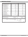
Power Specifications
Transformer Input: Primary input: 120 VAC, 60 Hz, Secondary output: 16 VAC 56 VA
Standby Battery: 12 VDC, 1.0 Amps Max. charging current
Auxiliary: 12 VDC output at 1.0 Amp Max*
Bell Output: 12 VDC at .7 Amp Max*
Note: The combined Auxiliary and Bell outputs total cannot exceed 1.9 Amps with a 56 VA Transformer. All circuits are inherent Power Limited except the red battery wire and AC terminal.
* For Commercial Fire installations, see the Compliance Instructions section.
1.4
Communication
Built-in dialer or network communication to DMP Model SCS-1R Receivers
Built-in Contact ID communication to non-DMP receivers
893A Dual Phone Line Module with phone line supervision
Can operate as a local panel
1.5
Panel Zones
Eight 1k Ohm EOL burglary zones (zones 1 to 8). Connect to 869 Class A module for burglary applications. Two 3.3k Ohm EOL powered zone with reset (zones 9 and 10).
Note: Use the supplied DMP Model 311 1k Ohm and DMP Model 301 3.3k Ohm resistors.
1.6
Keypad Bus
You can connect up to 15 of the following supervised keypads and expansion modules to the keypad bus:
• Alphanumeric Fire Command Centers or keypads
• Four- and/or single-zone expansion modules
• Single-zone detectors
• Access control modules
XR2500F Installation Guide
Digital Monitoring Products
1
Introduction
1.7
LX-Bus™
You can connect the following devices to the LX-Bus™ provided by the DMP 481 (supplied) or by the 462N,
481, 462P, 463G, and 472 Interface Cards up to the maximum number of LX-Bus™ addresses. See Accessory
Devices.
• Model 521LX or 521LXT Smoke Detectors with CleanMe
• Sixteen-, eight-, four- and/or single-zone expansion modules
• Single-zone detectors
• Relay output expansion modules
• Graphic annunciator modules
1.8
Outputs
The XR2500F provides two pre-installed Model 305 Single Pole, Double Throw (SPDT) relay outputs, each
rated 1 Amp at 30 VDC (power limited sources only). The XR2500F also provides four programmable open collector outputs rated for 30 VDC @ 50mA each. The
open collector outputs provide ground connection for a positive voltage source. A Model 300 Output Harness
is required to use these outputs and may be connected to a Model 860 Relay Output Module.
1.9 Relays
The XR2500F ships with two Model 305 Relays pre-installed to allow zone alarm control for the 866 NAC
Modules. When a fire alarm occurs the bell output is factory programmed to turn on and provide power to
the contacts of the relays. Specific zone programming determines whether one or both relays turn on signal
voltage to the 866 NACs. This allows control of the NACs by zone. 1.10 Zone Reference
The XR2500F has been pre-wired in the factory. The first 866 NAC module connects to Zone 1. The second
866 NAC module connects to Zone 2.
1.11 Compliance Instructions
For applications that must conform to a local authorities installation standard or a National Recognized Testing
Laboratory certificated system, please see the Wiring Diagrams for Notification Appliances and the Listed
Compliance Specifications section near the end of this guide for additional instructions.
Digital Monitoring Products
2
XR2500F Installation Guide
Introduction
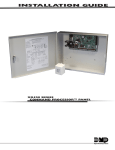
Mounting
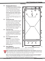
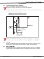
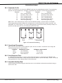
2.1
Mounting the Enclosure
The XR2500F must be mounted in a secure,
dry location to protect the unit from damage
due to tampering and the elements. The
enclosure can be either flush mounted or
surface mounted and includes a hinged door
with lock. The hole in the enclosure door
allows access to the Fire Command Center
without opening the door. Figure 1 illustrates
the mounting hole locations for the panel
enclosure.
The enclosure dimensions are 32” tall, 14.5”
wide, by 4” deep. The lid adds about 0.5” to
each side.
2.2
Hole for Flush
Mounting
Holes for Surface Mounting
Surface Mounting
The enclosure center hole should be attached
to a wall stud. Due to the enclosure weight,
especially the batteries, it is extremely
important to mount the enclosure on the
stud. Attach the two holes beside the center
hole to sheetrock to secure enclosure. When
mounting the enclosure, be sure to leave
room for the panel door to swing open. The
door lock should be easily accessible.
2.3
3/4" X 1/2" Knockouts
Holes for 1" screws for
Flush Mounting
Flush Mounting
The enclosure can also be flush mounted. Use
1” screws to secure the enclosure between
two studs using the two sets of holes on
the sides of the enclosure. Use the top and
bottom holes to secure to horizontal studs, if
necessary.
2.4
Fire Command Center LCD
Keyboard
A Fire Command Center LCD Keyboard
has been factory installed on the XR2500F
enclosure. A keyswitch has also been
installed and pre-wired to the left of the
keyboard. The user can turn the keyswitch to
enable the four function keys without opening
the enclosure door.
2.5
Metal Backplate
Battery Shelf
Additional Holes for Surface Mounting
Hole for Flush Mounting
The XR2500F components are pre-wired
Figure 1: Mounting the XR2500F Enclosure
and installed on a metal backplate. The
backplate can be easily removed to keep components safe during pre-wire activities. Remove AC and battery power from the XR2500F panel before removing the backplate. Disconnect all
battery, transformer, and the Fire Command Center LCD keyboard wires. From the panel, disconnect the AC
wires from terminals 1 and 2. Disconnect the battery wires either from the batteries or the panel terminals
3 and 4. Finally, disconnect the keyboard wires from panel terminals 7, 8, 9, and 10. Remove the screws securing the backplate to the enclosure. Loosen the two top screws that the backplate
hangs on. After loosening and removing the screws, lift the backplate up slightly and pull the backplate
toward you. When reinstalling the backplate, be sure all connections are secure. Figure 2 illustrates the backplate and the components. The backplate is shown in light gray. XR2500F Installation Guide
Digital Monitoring Products
3
Introduction
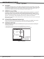
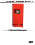
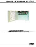
2.6
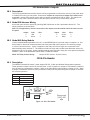
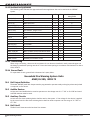
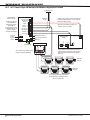
Wiring Diagram
The XR2500F system below shows the component layout. The wires shown in this guide have been factory
installed and connected. The dashed lines represent wires running underneath or behind a component. Detailed wiring diagrams for each supplied component appear in following sections of this guide.
WARNING
THIS UNIT MAY BE PROGRAMMED TO USE AN ALARM VERIFICATION FEATURE THAT RESULTS IN DELAY OF THE
SYSTEM ALARM SIGNAL FROM THE INDICATED CIRCUITS. THE TOTAL DELAY (CONTROL UNIT PLUS SMOKE
DETECTORS) SHALL NOT EXCEED 60 SECONDS. NO OTHER SMOKE DETECTOR SHALL BE CONNECTED TO THESE
CIRCUITS UNLESS APPROVED BY THE LOCAL AUTHORITY HAVING JURISDICTION (AHJ).
Verification Control Unit
Delay
Zones
WHITE
BLACK
GROU
ND
S
16 VAC
See LT-0759, 893A
Dual Phone Line
Module section
for complete 893A
information.
To Telco
866
Module
WHITE
Connected to
Enclosure Door
GREEN/
YELLOW
BLACK
GREEN
Commercial and Residential
Fire, Burglar, Holdup, and
Access Protected Premise Unit
S
Detector
Delay
Zones 9, 10, and all expanded
zones are suitable for Class B
(as applicable for the initiating
and signaling line circuits per
ANSI/UL 864 Table 48.2 or
48.3). Installation limits under
local Authority Having
Jurisdiction (AHJ).
S
Use Marking
Smoke
Model
866
Module
See LT-0759, Two 866
NAC Modules section for
complete 866 information.
56 VA
Transformer
S
S
S
S
S
S
10K EOL
10K EOL
To Notification
Appliances
TYPES OF SERVICE
Suitable for Mercantile Local
and Police Station Connect.
Suitable for Proprietary, PPU,
other technologies, local.
J3
Phone
Line
Suitable for manual fire alarm,
automatic fire alarm, sprinkler
supervisory, or water flow
alarm.
Power
LED
R
L
X
J22
Battery
Start
J8
PROG
AC AC +B
2
Red
1
From XR2500F
panel to 12 VDC.
3
–B BELL GND RED YEL GRN BLK SMK GND Z1 GND Z2
4
5
6
7
8
9
10
11
+
-
XR2500F Secondary Power Supply
1 Amp maximum charge current.
Use only 12 VDC rechargeable batteries.
Replace every 3 to 5 years.
12 VDC battery
12 13
14
J16
Reset
3
4
5
Outputs 3-6
Z3 GND Z4
15 16
17
Z5 GND Z6
18 19
20
Z7 GND Z8 Z9+ Z9– Z10+ Z10–
21 22
23
24 25
26
27
Expansion Zones
28
To Fire Command Center on enclosure door
Black
Suitable for Coded and March
Time signaling.
Output 1 OVC Output 2
Out1 Out2
Suitable for Household Fire and
Household Burglary.
NFPA 72
This equipment should be
installed in accordance with
the National Fire Alarm Code,
ANSI/NFPA 72 (National Fire
Protection Association,
Batterymarch Park, Quincy, MA
02269). Printed information
describing proper installation,
operation, testing,
maintenance, evacuation
planning, and repair service is
to be provided with this
equipment.
J1
Ethernet
Link LED
Power LED
Suitable for Standard or
Encrypted Central Station with
NET or CELL communication.
XR2500F
Command
Processor™
Panel
J4
Tamper
J6 Expansion
Card Slot
Suitable for Signaling and
Remote Station PPU DACT
Service.
-
+
Two 12 VDC batteries
connected in parallel with a
Model 318 Dual Battery
Harness. See Secondary
Power Supply section.
Refer to LT-0759, Standby
Battery Selection section
for battery standby times and
numbers of batteries to use.
12 VDC battery
Battery Compartment
Figure 2: XR2500F System
Digital Monitoring Products
4
XR2500F Installation Guide
Introduction
AC Connection
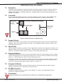
3.1
Transformers and AC Power Connection
The AC connection should be completed by a licensed electrician.
Never share the Fire Alarm Control Panel circuit with any other equipment.
The XR2500F comes supplied with a 16 VAC 56 VA transformer. The 16 VAC transformer white leads and black
leads must be connected to an unswitched 120 VAC 60 Hz power source with at least .87A available. Observe
wire colors and connect the transformer wires:
The Black transformer wires to the Black 120 VAC wire The White transformer wires to the White 120 VAC wire The Green/Yellow ground wire to the electrical ground Bracket
Nut
WHITE
BLACK
S
GREEN/
YELLOW
Connected to
Enclosure Door
Bracket
Nut
L-Bracket
WHITE
BLACK
GREEN
GROU
ND
SS
16 VAC
56 VA
Transformer
56 VA
Transformer
Violet
Gray
Terminal 1 Terminal 2
To XR2500F Panel
Figure 3: Transformers and AC Power Connection
Always ground the panel before applying power to any devices! Use 18 AWG or larger for all power
connections. The XR2500F must be properly grounded before connecting any devices or applying power
to the panel. Proper grounding protects against Electrostatic Discharge (ESD) that can damage system
components.
3.2 16 VAC Transformer
The 16 VAC 56 VA transformer supplies power to the XR2500F panel and is factory pre-wired. See Figure 3:
Transformers and AC Power Connection. Also refer to Figure 11: XR2500F Panel Wiring Diagram. 3.3
Earth Ground (GND)
The XR2500F terminal 4 must be connected to earth ground using 14 AWG or larger wire to provide proper
transient suppression. DMP recommends connecting to a cold water pipe, building ground, or ground rod
only. Do not connect to an electrical ground or conduit, sprinkler or gas pipes, or to a telephone company
ground.
XR2500F Installation Guide
Digital Monitoring Products
5
Introduction
Secondary Power Supply
4.1
Description
The XR2500F system includes pre-wired cables for connecting 12 VDC battery to the XR2500F panel. Observe
polarity when connecting all batteries. Use sealed lead-acid batteries only. Use the DMP Model 367, 368, 369, 365, 366, 12 VDC sealed lead-acid
rechargeable batteries. Batteries supplied by DMP have been tested to ensure proper charging with DMP
products.
Gel cell batteries cannot be used with the XR2500F panel. 4.2
Battery Connection to XR2500F Command Processor panel
For 12 VDC battery operation to the XR2500F, connect the black battery lead to the battery negative
terminal. The black battery wire connects to XR2500F panel terminal 4.
Connect the red battery lead to the battery positive terminal. The red battery wire connects to XR2500F
panel terminal 3. See Figure 11 and Figure 2. Add a second battery in parallel using the DMP Model 318 Dual Battery Harness. When wiring two batteries
with the Model 318 Dual Battery Harness, plug the Dual Battery Harness red male end into the panel red
female battery lead. Plug the Dual Battery Harness black male end into the panel black female battery
lead. Attach both Dual Wiring Harness female leads to the two batteries as described above. See Table 3:
Battery Calculations. Digital Monitoring Products
6
XR2500F Installation Guide
Introduction
Two 866 NAC Modules
5.1
Description
Each 866 provides one style W indicating circuit for supervising listed polarized notification appliances,
such as bells, strobes, and horns. See Table 1: Notification Appliances for a list of approved notification
appliances.
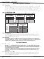
5.2
Connection
Each 866 module is pre-installed on the removable backplate using the standard three-hole configuration. The modules are factory pre-wired to each other and the XR2500F panel. Refer to the figure below and to
Figure 2: XR2500F System for wiring connections. Connect a 12 or 24 VDC regulated, power limited power supply listed for Fire Protective Signaling Systems to
terminals 2 and 4 of each module to provide Notification appliance power. Connect notification appliances
to terminals 5 and 6 of each module. Each module provides a zone of notification and can be activated
separately.
Normal/Silence Switch
866
Module #1
1
2
3
4
5
6
7
8
AUX PWR
GND
Alarm In
Bell PWR In
Bell Out +
Bell Out Bell Trouble
Bell Trouble
To XR2500F Output #1 (J2 pin #2)
Listed, Polarized
Notification Appliances
To XR2500F terminal 13 (Zone 1)
Pre-installed 1K EOL
See the Notification
Appliance section
Normal/Silence Switch
866
Module #2
1
2
3
4
5
6
7
8
AUX PWR
GND
Alarm In
Bell PWR In
Bell Out +
Bell Out Bell Trouble
Bell Trouble
To
To
To
To
XR2500F terminal 7
24 VDC Power Supply DC XR2500F Output #2 (J2 pin #5)
24 VDC Power Supply DC +
Pre-installed 1K EOL
To XR2500F terminal 15 (Zone 2)
To 24 VDC Power Supply
Listed, Polarized
Notification Appliances
See the Notification
Appliance section
Figure 5: 866 Modules Wiring
5.3
Bell Silence/Bell Trouble
A bell silence switch on the 866 module is provided to prevent indicating devices from sounding during
system testing. When the Silence position is selected, a 15-second delay occurs before the 866 bell trouble
contacts (terminals 7 and 8) open. Select the Normal position after testing to return the 866 module to
normal operation.
XR2500F Installation Guide
Digital Monitoring Products
7
Introduction
LX-Bus™ Operation
6.1
Description
The XR2500F Command Processor™ panel supports LX-Bus operation directly from the panel. Each LX-Bus
circuit provides 100 additional zones. Use J22 LX-Bus Header for the first 100 zones. Use the installed 481
Zone Expansion Interface Card for the next 100 zones. This provides a total of 200 expansion zones. To
install up to four additional Interface Cards use a Model 461 Interface Adaptor Card.
6.2
XR2500F On-board LX-Bus
To enable J22 to operate as an LX-Bus, place a jumper on the two pins next to the letter “L” on the J23
6‑Pin header. When using J22 as an LX-Bus, connect a DMP Model 300 4-wire Harness to the J22 4-pin
header labeled LX-BUS. This provides the first 100 LX-Bus zones numbered 500-599. Respect wire colors
when connecting devices and use all four wires. Reset the panel using the J16 jumper to activate LX-Bus
operation. See Connecting LX-Bus and Keypad Devices section for maximum wiring distances.
Note: Do NOT use shielded wire when using the LX-Bus. Do NOT connect the wires from the 4-wire harness
to the panel terminals.
6.3
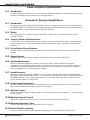
LX-Bus 481 Zone Expansion Interface Card
The 481 Zone Expansion Interface Card provides an additional 100 zones to the XR2500F. When used in
conjunction with the on-board J22 LX-Bus the 481 LX-Bus zones are numbered 600 to 699.
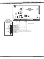
6.4
Installing the 481 Card
Remove AC and battery power from the XR2500F panel and ground yourself before handling and
installing the 481 Card.
1.Align the 481 Card 50 pin connector with the XR2500F panel J6 connector.
2. Press the 481 onto the J6 connector while applying even pressure to both sides.
Command Processor
Panel
481 Zone
Expansion
Interface
Card
J6 Interface Card
Connector
Zone Expansion
Harness Connectors
B
To LX-Bus Modules
Z5 GND Z6
18
19
20
21
Z7 GND Z8
22
23
24
Z9+ Z9- Z10+ Z10-
25
26
27
28
Red—Auxiliary Power
Yellow—Data In
Green—Data Out
Black—Ground
Figure 6: 481 Wiring
Digital Monitoring Products
8
XR2500F Installation Guide
Introduction
893A Dual Phone Line Module
7.1
Description
The 893A is a dual telephone line supervision module that allows the panel to indicate a phone line failure
to the premises and the central monitoring station. After the 893A senses a failure on the main line, it
switches to the backup, or secondary, phone line. The 893A installs on the removable backplate above the
XR2500F circuit board.
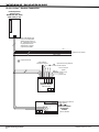
7.2
Connection
The pre-wired 893A connects the panel to the public telephone network through an installed DMP 356 RJ
Cable between the XR2500F panel J3 connector and the 893A Module J3 connector labeled PANEL. Factory pre-wired
to XR2500F panel
Phone Jack
Connector, J3
893A Dual Telephone Line Module
J3
PANEL
Communication Jumpers:
Both Set both Jumpers
DD
MPX
P10
Factory pre-wired
to XR2500F panel
J10 Connector
J1
J2
To Primary
telephone line
J4
MAIN
DD
MPX
J5
BACKUP
Processor
Stopped Buzzer
To Secondary telephone line
Figure 8: 893A Dual Phone Line Module Wiring
7.3
Jumper Settings
The 893A module has two sets of jumpers. Both communication jumpers must be set for DD (digital dialer)
operation. Do not set the 893A jumpers next to MPX. The 893A Module supports multiplex operation, but
the XR2500F panel does not.
7.4
Digital Dialer
You can configure the 893A to provide two lines of digital dialer. Maximum line impedance is 100 Ohms. The
XR2500F is preset at the factory for Digital Dialer. The Main modular jack (J4) is used for the primary digital
dialer line. The Backup modular jack (J5) is used for the secondary digital dialer line.
7.5
Phone Line Monitor
The 893A uses a phone line monitor for the main and backup phone lines. When sending a report, the 893A
verifies the main phone line is working before sending data. If the line is bad, the module tests the backup
phone line. The 893A sends the report on the first working phone line.
The phone line monitor has a two-minute trouble delay and a one-minute restore delay. Phone line trouble
is displayed in the Fire Command Center LCD Status List as a System Trouble. The Fire Command Center
LCD is factory programmed to display system troubles in the Status List.
7.6
Processor Fail Buzzer
The 893A module also monitors the panel CPU and sounds a trouble buzzer whenever either the panel
processor is reset using J16 or the processor stops functioning.
7.7
J10 893A Connector
The 893A Dual Phone Line Module connects to the XR2500F J10. Refer to the 893A Installation Sheet
(LT-0135) for complete information.
7.8
Ground start
Ground start phone service cannot be used on commercial or residential fire applications.
XR2500F Installation Guide
Digital Monitoring Products
9
Introduction
7.9
Notification
The user must not repair registered terminal equipment. In case of trouble, immediately unplug the device
from the telephone jack. The factory warranty provides for repairs. Registered terminal equipment may
not be used on party lines or in connection with coin telephones. Notify the telephone company with the
following information:
a. The particular line(s) where the service is connected
b. The FCC registration number
c. The ringer equivalence
d. The device make, model, and serial number (see the serial # sticker on the panel)
7.10 FCC Registration
The Model XR2500F complies with Part 68 of the FCC rules and the requirements adopted by the ACTA. On
the outside of the enclosure of this equipment is a label that contains, among other information, a product
identifier in the format US:CCKAL00BXR500. If requested this number must be provided to the telephone
company.
A plug and jack used to connect this equipment to the premises wiring and telephone network must comply
with the applicable FCC Part 68 rules and requirements adopted by the ACTA. See installation instructions
for details.
The Ringer Equivalence Number (REN) is used to determine the number of devices that may be connected
to a telephone line. Excessive RENs on a telephone line may result in the devices not ringing in response to
an incoming call. In most but not all areas, the sum of RENs should not exceed five (5.0). To be certain of
the number of devices that may be connected to a line, as determined by the total RENs, contact the local
telephone company.
If the XR2500F causes harm to the telephone network, the telephone company will notify you in advance
that temporary discontinuance of service may be required. But if advance notice isn’t practical, the
telephone company will notify the customer as soon as possible. Also, you will be advised of your right to
file a complaint with the FCC if you believe it is necessary.
The telephone company may make changes in its facilities, equipment, operations or procedures that could
affect the operation of the equipment. If this happens the telephone company will provide advance notice
in order for you to make necessary modifications to maintain uninterrupted service.
If trouble is experienced with the Model XR2500F, for repair or warranty information, please contact DMP at
the address and telephone number listed on the back of this document. If the equipment is causing harm to
the telephone network, the telephone company may request that you disconnect the equipment until the
problem is resolved.
If your premises has specially wired alarm equipment connected to the telephone line, ensure the
installation of the XR2500F does not disable your alarm equipment. If you have questions about what will
disable alarm equipment, consult your telephone company or a qualified installer.
Caution: To ensure proper operation, this equipment must be installed according to the installation
instructions in this manual. To verify that the equipment is operating properly and can successfully report an
alarm, this equipment must be tested immediately after installation, and periodically thereafter, according
to the test instructions in this document and the XR500 Series Programming Guide (LT-0679). Additionally,
verification of Line Seize capability should be made immediately after installation, and periodically
thereafter, in order to ensure that this equipment can initiate a call even when other equipment (telephone,
answering system, computer modem, etc.) connected to the same line is in use.
Digital Monitoring Products
10
XR2500F Installation Guide
Introduction
Fire Command Center
8.1
Description
The XR2500F provides an LCD display and 20-key keyboard for programming and system user operation. The
Fire Command Center is installed on the XR2500F enclosure door. A keyswitch is installed and pre-wired
to the left of the keyboard. The user must turn the keyswitch to enable the four function keys. See the
illustration below.
Fire Command Center
POWER
TROUBLE
ALARM
SILENCE
RESET
ABC
TEST
MNO
DEF
1
GHI
2
JKL
3
4
ENABLE
DRILL
PQR
STU
5
6
9
0
YX
VWX
7
8
COMMAND
Figure 10: Fire Command Center LCD and Keyboard
8.2 Connection
The display and keyboard are factory pre-wired to the XR2500F panel terminals 7, 8, 9, and 10. For standby
battery calculations, the display draws 92mA of current in normal standby or alarm condition. See Panel
Standby Battery Calculations. The keyswitch is pre-wired to the membrane keyboard. 8.3
Remote Fire Command Center
Up to fifteen Model 630F Remote Fire Command Centers may be remotely attached to the XR2500F system. See the 630F Installation Guide (LT-0741) for additional information. XR2500F Installation Guide
Digital Monitoring Products
11
Introduction
Expansion
9.1
Zone Expansion
Up to 574 fire and burglary zones are available on the XR2500F using DMP Security Command keypad remote
zone capability and zone expansion modules. The panel keypad data bus supports up to sixteen supervised
device addresses with each address supporting up to four programmable expansion zones.
Up to 500 zones are available using the on-board LX-Bus along with additional expansion modules. Use the
461 Interface Adaptor, 462N, 462P, 463G, or 481 interface cards, and any combination of sixteen, eight, four,
and single point zone expander modules and single point LX-Bus detectors.
Combined current requirements of additional modules may require an additional power supply. See the
710/710F Bus Splitter/Repeater Installation Guide (LT-0310). Refer to the Standby Battery Calculations
section when calculating power requirements. Note: Do not use shielded wire for LX-Bus or Keypad Bus circuits. 9.2
Output Expansion
Note: Do not use shielded wire for LX-Bus or Keypad Bus circuits. In addition to the two SPDT relays and four programmable open collector outputs on the XR2500F, you can
also connect up to 25 programmable Model 716 Output Expansion Modules to each LX-Bus. These modules
can provide an additional 500 programmable SPDT relays.
The XR2500F provides 100 Output Schedules you can use for programming the 716 to perform a variety of
annunciation and control functions. You can also assign the 716 outputs to any panel Output Options such as
Fire Alarm, Communication Fail, or Phone Trouble Outputs. Refer to the 716 Installation Guide (LT-0183).
The LX-Bus™ also supports the Model 717 Graphic Annunciator Module. Each 717 module supplies 20
switched ground outputs that follow the state of their assigned zones. Note: The 717 supports the first eight keypad bus zones. To follow Keypad Bus zones nine through 16, install
multiple 716 modules. Refer to the 717 Installation Guide (LT-0235) and 716 Installation Guide (LT‑0183).
Digital Monitoring Products
12
XR2500F Installation Guide
Installation
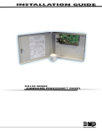
Accessory Devices
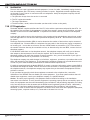
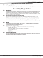
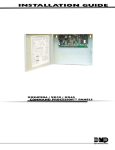
10.1 Wiring Diagram
The XR2500F system below shows some of the accessory modules for use in various applications. A brief
description of each module follows.
s
s
Form C Relays (J2)
Output Color Code–Model 431 Harness
Output 2 N/O Orange/White
Output 2 Com White/Gray
Output 2 N/C Violet/White
Output 1 N/O Orange
Output 1 Com Gray
Output 1 N/C Violet
J4
Tamper
Link LED
Power LED
J1 s
Ethernet
s
RS-232
J22
LX-Bus
K7
RED
BLACK
Cold Water
Pipe Earth
Ground
GROUND
10k
Ohm
Bell
Bell cutoff time
range is 5 to 99
minutes marchtime
and non-coded.
s
s
s
Heat detectors, pull
stations, or any other
contact devices listed
for Fire Protective
Signaling can be
connected to zones
9 and 10.
Zones 9 and 10 and
Model 715 compatibility
identifier: A
S
S
15 16
S
S
S
1k
1k
Ohm Ohm
17
S
18 19
S
S
1k
1k
Ohm Ohm
20
S
S
21 22
S
23
S
S
1k
1k
Ohm Ohm
J16
Reset
S
24 25
S
26
27
Zone
9
S
1k
1k
Ohm Ohm
s = Supervised Circuit
s s
Maximum operating
range: 9.8 VDC to
14.0 VDC.
Class B (Style A).
Z7 GND Z8 Z9+ Z9– Z10+ Z10–
Zone 8
14
Zone 3
12 13
Z3 GND Z4 Z5 GND Z6
Zone 2
11
Zone 1
10
22 gauge minimum
s
s
9
22 gauge minimum
s
8
S
28
Zone
10
S
S
S
Verification Control Unit
Zones
Delay
______
13.6 sec.
RED
Model 630F
60mA at 8 to 14.5 VDC
Smoke
Model
______
Detector
Delay
____sec.
Zone Expander
Model 715
7mA @ 12 VDC
Models 715-8, 715-16
20mA @ 12 VDC
RED
YELLOW
GREEN
Keypads
Zones 9, 10, and all
expanded zones are
suitable for Class B (as
applicable for the
initiating and signaling
line circuits per ANSI/UL
864 Table 48.2 or 48.3).
Installation limits under
local Authority Having
Jurisdiction (AHJ).
Using verification delays
on zones 9 and 10 is
optional. Use the
delays marked on the
smoke detectors or
the smoke detector
installation wiring
diagram.
3.3k
3.3k
Ohm
Ohm
Resistor Resistor
Auxiliary Power
Total current combined from
terminals 7, 11, 25, and 27
1.9 Amp Max
BLACK
6
s
7
22 gauge minimum
5
GREEN
4
22 gauge minimum
3
RED
Bell
12 VDC nominal
Minimum cutoff time is
5 minutes.
.7 Amp Max
2
YELLOW
Secondary Power Supply
1.0 Amps Max. charging
current. Use only 12 VDC
rechargeable batteries.
DMP Models 365, 366, 367,
368, or 369. Replace
batteries every 3 to 5 years.
1
Rear
Tamper
Outputs 3-6
AC AC +B –B BELL GND RED YEL GRN BLK SMK GND Z1 GND Z2
Zone 7
K6
J11
3
4
5
6
Zone 5
J2
J8
PROG
DMP Transformer
16 VAC 56 VA
Class 2 Wire-in.
Front
Tamper
J6
Listed Resistors
1.0k Ohm - DMP Model 311
3.3k Ohm - DMP Model 309
10K Ohm - DMP Model 308
Output 1 OVC Output 2
J10
Battery
Start
¼"
Zone 6
L
X
Wiring on terminals 5 through 22 must
exit right and maintain 1/4" separation
from the AC and battery positive wiring.
Zone 4
J21
Power J23
R
LED
AC Wiring must be in conduit and exit
out the left side of the enclosure.
Annunciator Outputs (J11)
Output Color Code
Output 3
Red
Output 4
Yellow
Output 5
Green
Output 6
Black
Out1 Out2
J3 s
Phone Line
481 Zone Expansion Interface Card
XR2500F
Command Processor™
Panel
BLACK
Fire Command Center
POWER
TROUBLE
ALARM
SILENCE
RESET
ABC
TEST
MNO
DEF
1
GHI
2
JKL
3
4
ENABLE
WARNING: Incorrect
connections may cause
damage to the unit.
DRILL
PQR
STU
5
6
9
0
YX
VWX
7
8
COMMAND
Keyswitch Arming
can be connected
to any zone. See
LT-0681.
s
s
Zone Expander
Model 714
7mA @ 12 VDC
Models 714-8, 714-16
20mA @ 12 VDC
Zone
Expander
Model 711
7mA @ 12
VDC
Smoke
Detector
CAUTION: DO NOT USE LOOPED WIRE
UNDER TERMINALS. BREAK WIRE RUN TO
PROVIDE SUPERVISION OF CONNECTIONS.
S
S
S
S
S
S
1k Ohm 1k Ohm 1k Ohm
Use UL Listed Power
Supervision Relay
rated at 12 VDC.
1k Ohm
S
S
S
S
S
S
S
S
3.3k Ohm 3.3k Ohm 3.3k Ohm 3.3k Ohm
S
S
1k Ohm
WARNING
THIS UNIT MAY BE PROGRAMMED TO USE AN ALARM VERIFICATION
FEATURE THAT RESULTS IN DELAY OF THE SYSTEM ALARM SIGNAL FROM
THE INDICATED CIRCUITS. THE TOTAL DELAY (CONTROL UNIT PLUS
SMOKE DETECTORS) SHALL NOT EXCEED 60 SECONDS. NO OTHER
SMOKE DETECTOR SHALL BE CONNECTED TO THESE CIRCUITS UNLESS
APPROVED BY THE LOCAL AUTHORITY HAVING JURISDICTION (AHJ).
Figure 12: Typical XR2500F Wiring Diagram
10.2 Lightning Protection
Metal Oxide Varistors and Transient Voltage Suppressors help protect against voltage surges on XR2500F input
and output circuits. Additional surge protection is available by installing the DMP 370 or 370RJ Lightning
Suppressors.
XR2500F Installation Guide
Digital Monitoring Products
13
Installation
10.3 Accessory Devices
Interface Adaptor and Interface Cards
461 Interface Adaptor Card
Allows you to connect two or more expansion interface cards to the XR2500F panel. The 461 is an
expansion board that plugs into the panel J6 Interface Connector and is required when using two or more
Interface Cards. Use combinations of Interface Cards for expanding zones, network interfacing, and local
printing.
462N Network Interface Card
Allows you to connect the XR2500F to any compatible data network and use its communication capability
in place of standard dial out telephone lines. The 462N also provides an LX-Bus™ for connecting zone and
output expansion modules to the panel.
462P Printer Interface Card
Allows you to connect the XR2500F to any compatible serial printer providing the user with real-time event
recording. The 462P also provides an LX-Bus™ for connecting zone and output expansion modules.
463G Digital Cellular Communicator
Card
Allows you to connect the XR2500F to any compatible GPRS/SMS network and use its communication in
place of standard dial out lines. The 463G also provides and LX-Bus™ for connecting zone and output
expansion modules to the panel.
481 Expansion Interface Card
Provides one LX-Bus for connecting up to 100 zone and output expansion modules.
Zone and Output Expansion Modules
710/710F Bus Splitter/Repeater
Allows you to increase keypad or LX-Bus™ wiring distance to 2500 feet. Model 710F is for 24 VDC
applications.
711 Single Point Zone Expanders
Provides one Class B zone for connecting devices.
714, 714-8, 714-16 Zone Expanders
Provides Class B zones for connecting non-powered fire devices.
715, 715-8, 715-16 Zone Expanders
Provides 12 VDC Class B powered zones for connecting smoke detectors, glassbreak detectors, and other
2- or 4-wire devices.
725 Zone Expanders
Provides 24 VDC Class B powered zones for connecting smoke detectors, glassbreak detectors, and other 2or 4-wire devices. Requires 710F Bus Splitter/Repeater.
716 Output Expander
Provides four Form C relays (SPDT) and four switched grounds (open collector) for use in a variety of
remote annunciation and control applications.
717 Graphic Annunciator Module
Provides 20 zone following annunciator outputs (open collector) for use in a variety of remote annunciation
and control applications for use on the keypad bus only.
733, 734 Wiegand Interface Cards
Provides system codeless entry, and arming and disarming using access control readers.
Indicating and Initiating Devices
865 Supervised Style W or X
Notification Circuit Module
Provides supervised alarm current when using the XR2500F panel bell output and up to 5 Amps at 12 or 24
VDC when using a listed auxiliary power supply. The 865 can supervise 2-wire or 4-wire style circuits for
opens and shorts with individual LED annunciation.
866 Style W Notification Circuit
Module
Provides supervised alarm current using the XR2500F panel bell output and up to 5 Amps at 12 or 24 VDC
when using a listed auxiliary power supply. The 866 can supervise 2-wire Style W circuits for opens and
shorts.
867 Style W LX-Bus Notification
Circuit Module
Provides supervised alarm current using the XR2500F panel bell output and up to 5 Amps at 12 or 24 VDC
when using a listed auxiliary power supply. The 867 connects to the XR2500F panel LX-Bus™ and provides
one 2-wire Style W notification circuit for open and short conditions. Individual Bell Relay addresses Bell
Ring styles.
869 Dual Class A Style D Initiating
Module
Provides two Class A, Style D, 4-wire initiating zones for connecting waterflow switches and other
non‑powered fire and burglary devices.
Accessory Modules and Keypads
893A Dual Phone Line Module
* ePAD™ Virtual Keypads
LCD keypads
Allows you to supervise two standard phone lines connected to an XR2500F panel. The 893A module
monitors the main and backup phone lines for a sustained voltage drop and alerts users when the phone
line is bad.
Allows users to control the security system from any computer in the world using the Internet.
Allows you to control the panel from various remote locations. Connect up to sixteen supervised Model
630F Remote Fire Command Center, Model 690, 790, 693/793 Security Command™ keypads, 7060, 7063,
7070, 7073, 7160, 7163, 7170, 7173 Thinline™ keypads, 7060A, 7063A, 7070A, 7073A Aqualite™ keypads,
or 7760 Clear Touch™ keypad to the keypad bus using terminals 7, 8, 9, and 10.
Addressable Smoke Detectors
521LX, 521LXT
Single-zone, addressable module conventional smoke/smoke heat detectors that connect to the LX-Bus.
Includes remote maintenance reporting, drift compensation, and multi-criteria detection.
* These devices have not been investigated and shall not be used in listed installations.
Table 5: Accessory Devices
Digital Monitoring Products
14
XR2500F Installation Guide
Installation
10.4 Mounting Keypads and Zone Expansion Modules
LCD keypads have removable covers that allow mounting the keypad to a wall or other flat surface using the
screw holes on each corner of the base. Before mounting the base, connect the keypad wire harness leads
to the keypad cable from the panel and to any device wiring run to that location. Then attach the harness to
the pin connector on the PC board, mount the base, and install the keypad cover making sure all of the keys
extend through their respective holes.
For mounting keypads on solid walls, or for applications where conduit is required, use the Model 695 1-1/2”
deep or the Model 696 1/2” deep backboxes.
The DMP 711, 714, 715, 716, and 717 modules are each contained in molded plastic housings with removable
covers. The base provides you with mounting holes for installing the unit to a wall, switch plate, or other
surface.
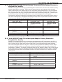
10.5 Connecting LX-Bus and Keypad Bus Devices
Several factors determine the DMP LX-Bus™ and keypad bus performance characteristics: the wire length and
gauge used, the number of devices connected, and the voltage at each device. When planning an LX-Bus™
and keypad bus installation, keep in mind the following information:
1. DMP recommends using 18 or 22-gauge unshielded wire for all keypad and LX-Bus circuits. Do not use
twisted pair or shielded wire for LX-Bus and keypad bus data circuits. 2.On keypad bus circuits, to maintain auxiliary power integrity when using 22-gauge wire do not exceed 500
feet. When using 18-gauge wire do not exceed 1,000 feet. To increase the wire length or to add devices,
install an additional power supply that is listed for Fire Protective Signaling, power limited, and regulated
(12 VDC nominal) with battery backup.
Note: Each panel allows a specific number of supervised keypads. Add additional keypads in the
unsupervised mode. Refer to the panel installation guide for the specific number of supervised keypads
allowed.
3.Maximum distance for any one bus circuit (length of wire) is 2,500 feet regardless of the wire gauge. This
distance can be in the form of one long wire run or multiple branches with all wiring totaling no more
than 2,500 feet. As wire distance from the panel increases, DC voltage on the wire decreases. Maximum
number of LX-Bus devices on the first 2,500 foot circuit is 40 devices. 4. Maximum voltage drop between the panel (or auxiliary power supply) and any device is 2.0 VDC. If the
voltage at any device is less than the required level, add an auxiliary power supply at the end of the
circuit. When voltage is too low, the devices cannot operate properly. For additional information refer to the LX-Bus/Keypad Bus Wiring Application Note (LT-2031).
Expansion Interface Cards (Models 481, 462N, 462P, 463G, and 472)
The LX-Bus provided on these cards requires only a 4-wire cable between the card and any devices
connected to the bus. You can connect devices (zone or output expansion modules) together on the same
cable or provide separate runs back to the card. Each LX-Bus provides up to 100 zones or outputs. Note: Do not use twisted pair or shielded wire when connecting an LX-Bus or keypad bus. XR2500F Installation Guide
Digital Monitoring Products
15
Installation
Battery Information
11.1 Battery Only Restart
When powering up the XR2500F panel without AC power, briefly short across the battery start pads to pull in
the battery cutoff relay. The leads need a momentary short only. Once the relay has pulled in, the battery
voltage holds it in that condition. If the XR2500F panel is powered up with an AC transformer, the battery
cutoff relay is pulled in automatically. For battery start pad location refer to Figure 11.
11.2 Battery Replacement Period
DMP recommends replacing the battery every 3 to 5 years under normal use.
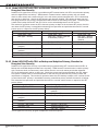
11.3 Discharge/Recharge
The XR2500F battery charging circuit float charges at 13.9 VDC at a maximum current of 1.0 Amps using a
56 VA transformer. Listed below are the various battery voltage level conditions:
Battery Trouble:
Below 11.9 VDC
Battery Cutoff:
Below 10.2 VDC
Battery Restored: Above 12.6 VDC
11.4 Battery Supervision
The XR2500F tests the battery when AC power is present. The test is done every three minutes and lasts for
five seconds. During the test, the panel places a load on the battery; if the battery voltage falls below 11.9
VDC a low battery is detected. If AC power is not present, a low battery is detected any time the battery
voltage falls below 11.9 VDC.
If a low battery is detected with AC power present, the test repeats every two minutes until the battery
charges above 12.6 VDC indicating the battery has restored voltage. If a weak battery is replaced with a
fully charged battery, the restored battery is not detected until the next two minute test completes.
11.5 Battery Cutoff
The panel disconnects the battery any time the battery voltage drops below 10.2 VDC. This prevents battery
deep discharge damage.
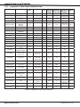
12.6 XR2500F Power Requirements
During AC power failure, the XR2500F panel and all auxiliary devices connected to the XR2500F draw their
power from the battery. All devices must be taken into consideration when calculating the battery standby
capacity. On the following page is a list of the XR2500F panel power requirements.
• XR2500F Command Processor™ Panel
• The Fire Command Center
• 893A Dual Phone Line Module
• Two 866 NAC modules
• 481 Zone Expansion Interface Card
Then add the additional current draw of Remote Fire Command Centers, Security Command keypads, zone
expansion modules, smoke detector output, and any other auxiliary devices used in the system for the total
current required. The total is then multiplied by the number of standby hours required to calculate the total
ampere-hours required.
See the XR2500F Standby Battery Power Calculations chart on the following page and the Standby Battery
Selection information on the next page.
Digital Monitoring Products
16
XR2500F Installation Guide
Installation
11.7 XR2500F Standby Battery Calculations
Standby Battery Power Calculations
XR2500F Control Panel
Relay Outputs 1-2 (ON)
Switch Grounds 3-6 (ON)
Active Zones 1-8
Active Zones 9-10
2-Wire Smoke Detectors
Panel Bell Output
Standby Current
Qty ___ 1_
x
Qty ______
x
Qty ______
x
Qty ______
180mA __180_mA
Alarm Current
Qty ____1_
x
180mA __180_mA
30mA ______
Qty ______
x
5mA ______
Qty ______
x
5mA ______
x
1.6mA ______
Qty ______
x
*2mA ______
Qty ______
x
4mA ______
Qty ______
x
30mA ______
Qty ______
x
0.1mA ______
Qty ______
x
30mA ______
0.1mA ______
1500mA ______mA
893A Dual Phone Line Module
Qty ______
x
461 Interface Adaptor Card
12mA ______
Qty ______
7mA ______
x
50mA ______
x
7mA ______
462N Network Interface Card
Qty ______
x
50mA ______
Qty ______
x
50mA ______
462P Printer Interface Card
Qty ______
x
50mA ______
Qty ______
x
50mA ______
463G Digital Cellular Communicator Card
Qty _______
x
21mA ______
Qty _______
x
21mA ______
481 Expansion Interface Card
Qty ______
x
15mA ______
Qty ______
x
15mA ______
860 Relay Output Module (one relay active)
All four relays active
Qty _______
x
34mA ______
138mA ______
Qty _______
x
34mA ______
138mA ______
865 Style Y or Z Notification Module
Qty ______
x
26mA ______
Qty ______
x
85mA ______
866 Style W Notification Module
Qty ______
x
45mA ______
Qty ______
x
76mA ______
867 LX-Bus Style W Notification Module
Qty ______
x
30mA ______
Qty ______
x
86mA ______
630F Remote Fire Command Center
Qty ______
x
63mA ______
Qty ______
x
92mA ______
690 Security Command Keypad
Qty ______
x
77mA ______
Qty ______
x
84mA ______
693/793 Security Command Keypad
Active Zones (EOL Installed)
Qty ______
x
92mA ______
Qty ______
x
120mA ______
1.6mA ______
Qty ______
x
*2mA ______
790 Security Command Keypad
Active Zones (EOL Installed)
Qty ______
7060/7060A/7160 Thinline Keypad
Qty ______
7063/7063A/7163 Thinline Keypad
7070/7070A/7170 Thinline Keypad
Active Zones (EOL Installed)
7073/7073A/7173 Thinline Keypad
Active Zones (EOL Installed)
Qty ______
733 Wiegand Interface Module
Active Zones (EOL Installed)
Annunciator (ON)
Qty ______
Qty ______
734 Wiegand Interface Module
Active Zones (EOL Installed)
Annunciator (ON)
Qty ______
x
Qty ______
x
Copy Sub-Totals to next page
*Based on 10% of active zones in alarm.
XR2500F Installation Guide
x
77mA ______
Qty ______
x
84mA ______
1.6mA ______
Qty ______
x
*2mA ______
x
80mA ______
Qty ______
x
84mA ______
Qty ______
x
86mA ______
Qty ______
x
112mA ______
Qty ______
x
72mA ______
Qty ______
x
87mA ______
1.6mA ______
Qty ______
x
*2mA ______
x
93mA ______
Qty ______
x
112mA ______
1.6mA ______
Qty ______
x
*2mA ______
x
30mA ______
Qty ______
x
30mA ______
x
1.6mA ______
Qty ______
x
*2mA ______
Qty ______
x
20mA ______
30mA ______
Qty ______
x
30mA ______
1.6mA ______
Qty ______
x
*2mA ______
Qty ______
x
20mA ______
Sub-Total Standby ______mA
Sub-Total Alarm ______mA
Digital Monitoring Products
17
Installation
Standby Battery Power Calculations
736P POPIT Interface Module
Radionics Popex, POPITs, OctoPOPITs
Standby Current
x
Qty
Qty
Qty
Qty
______
______
______
______
x
x
x
x
1.6mA ______
7mA ______
Qty ______
Qty ______
x
x
*2mA ______
7mA ______
x
x
1.6mA ______
20mA ______
Qty ______
Qty ______
x
x
*2mA ______
20mA ______
Qty ______
Qty ______
x
x
1.6mA ______
7mA ______
Qty ______
Qty ______
x
x
*2mA ______
7mA ______
Qty ______
x
4mA ______
Qty ______
x
*30mA ______
Qty ______
Qty ______
x
x
.1mA ______
20mA ______
Qty ______
Qty ______
x
x
.1mA ______
20mA ______
Qty ______
x
4mA ______
Qty ______
x
*30mA ______
Qty ______
Qty ______
x
x
.1mA ______
13mA ______
Qty ______
Qty ______
x
x
.1mA ______
13mA ______
717 Graphic Annunciator Module
Annunciator Outputs
Qty ______
x
10mA ______
Qty ______
Qty ______
x
x
12mA ______
10mA ______
521LX, 521LXT Smoke Detectors
Aux. Powered Devices on Terminals 7 and 11
Other than Keypads and LX-Bus Modules
Qty ______
x
Qty ______
Qty ______
x
x
714 Zone Expansion Module
Active Zones (EOL Installed)
714-8, 714-16 Zone Expansion Module
Active Zones (EOL Installed)
715 Zone Expansion Module
Active Zones (EOL Installed)
2-Wire Smokes
715-8, 715-16 Zone Expansion Modules
Active Zones (EOL Installed)
2-Wire Smokes
716 Output Expansion Module
Active Form C Relays
x
Qty
Qty
Qty
Qty
______
______
______
______
x
x
x
x
___mA
32mA
40mA
11mA
Qty ______
Qty ______
x
x
Qty ______
Qty ______
Alarm Current
Qty ______
710 Bus Splitter/Repeater Module
710F Fire Bus Splitter/Repeater Module
711 Zone Expansion Module
Active Zones (EOL Installed)
Qty ______
25mA ______
______
______
______
______
8.8mA ______
______mA
25mA ______
___mA
32mA
40mA
11mA
______
______
______
______
1mA ______
*28mA ______
______mA
This page only
Sub-Total Standby ______mA
Sub-Total Alarm ______mA
Sub-Totals from previous page
Sub-Total Standby ______mA
Sub-Total Alarm ______mA
Total Standby ______mA
Total Alarm ______mA
*Based on 10% of active zones in alarm
Total Standby______mA x number of Standby Hours needed ______ =
Total Alarm ______mA
_______mA-hours
+_______mA-hours
Total
_______mA-hours
X
.001
= _______Amp-hrs
Digital Monitoring Products
18
Required
XR2500F Installation Guide
Installation
11.8 Standby Battery Selection
To choose the type and number of batteries needed for 24, 60, or 72 hours of standby power based on the
Amp Hours Required calculation from the XR2500F Power Requirements section, perform the following:
1.Select the desired standby hours required from the table below: 24, 60, or 72 hours
2.Select the desired battery size: Model 368 (12 VDC 4.5 Ah), Model 369 (12 VDC 7 Ah),
Model 367 (12 VDC 7.7 Ah), Model 365 (12 VDC 9 Ah), Model 366 (12 VDC 18 Ah).
3.Select a Max. Ah Available number that is just greater than the number calculated as the Amp Hours
Required.
4.Install the number of batteries shown in the corresponding No. of Batteries required column.
Example: If the Amp Hours Required calculation equals 22 Ah for 24 hours of standby time and 4.5 Ah
batteries are desired, install six (6) Model 368 (12 VDC, 4.5 Ah) batteries.
For listed installations, all batteries shall be installed in a DMP Model 341, 349, 350, or 352S enclosure
and all wiring shall run through conduit. The enclosure shall be installed to the left of the XR2500F
enclosure to ensure Battery and AC wire separation.
24 hours of standby power
4.5 Ah Batteries
7 Ah Batteries
7.7 Ah Batteries
9 Ah Batteries
18 Ah Batteries
Max. Ah No. of
Max. Ah No. of
Max. Ah No. of
Max. Ah No. of
Max. Ah No. of
Available Batteries
Available Batteries
Available Batteries
Available Batteries
Available Batteries
8
2
6
1
6
1
8
1
16
1
12
3
12
2
13
2
16
2
32
2
16
4
18
3
20
3
24
3
48
3
20
5
24
4
27
4
32
4
24
6
31
5
34
5
40
5
28
7
37
6
41
6
32
8
43
7
36
9
Note: 48 hours is the typical battery recharge time for any of the Number of
Batteries shown in this section.
40
10
60 hours of standby power
7 Ah Batteries
7.7 Ah Batteries
Max. Ah No. of
Max. Ah No. of
Available Batteries
Available Batteries
13
2
14
2
20
3
22
3
27
4
29
4
33
5
37
5
40
6
44
6
47
7
52
7
54
8
59
8
60
9
67
9
67
10
9 Ah Batteries
Max. Ah No. of
Available Batteries
17
2
26
3
34
4
43
5
52
6
61
7
69
8
18 Ah Batteries
Max. Ah No. of
Available Batteries
17
1
34
2
52
3
69
4
Note: 48 hours is the typical battery
recharge time for any of the Number
of Batteries shown in this section.
72 hours of standby power
9 Ah Batteries
18 Ah Batteries
Max. Ah No. of
Max. Ah No. of
Available Batteries
Available Batteries
16
2
16
1
25
3
33
2
33
4
50
3
42
5
67
4
50
6
59
7
Note: 72 hours is the typical battery recharge time required for any of the Number
of Batteries shown in this section.
67
8
Note: If the Amp Hours Required calculation is greater than any Max. Ah Available number shown on a table, then
add power supply(s) to power some system devices allowing the Amp Hours Required calculation to be reduced. See
the 710/710F Bus Splitter/Repeater Installation Guide (LT-0310).
XR2500F Installation Guide
Digital Monitoring Products
19
Installation
Bell Output
12.1 Terminals 5 and 6
Terminal 5 supplies positive 12 VDC regulated power for alarm bells or horns. This output can be steady,
pulsed, or temporal depending upon the Bell Action specified in Output Options. Terminal 6 is the ground
reference for the bell circuit. This supervised output detects 10k Ohms or less as normal. The indicating
appliance can supply this resistance. If using a horn or siren, a 1k Ohm 1/2 W EOL resistor (provided) should
be added across the bell circuit to provide supervision. See the Notification Appliance section for a list of
approved notification appliances and the Wiring Diagrams for connections.
Keypad Bus
13.1 Description
XR2500F panel terminals 7, 8, 9, and 10 are for the keypad bus. In addition to Fire Command Centers and
Remote Fire Command Centers, you can connect up to fifteen supervised keypads and multiple unsupervised
keypads to the XR2500F. In addition to Security Command keypads, you can also connect any combination
of zone expansion modules, 5845LX Glassbreak detectors, and 6155LX PIRs to the data bus. Refer to the
specific device Installation sheet for the maximum number of keypad Bus devices.
Refer to the section titled LX-Bus for complete information about the LX-Bus 4-pin header and expansion
slot.
Note: Do not use shielded wire for LX-Bus/Keypad Bus circuits. 13.2 Terminal 7 - RED
This terminal supplies positive 12 VDC regulated to power Fire Command Centers and zone expansion
modules. Terminal 7 also supplies power for any auxiliary device. The ground reference for terminal 7 is
terminal 10.
The output current is shared with the smoke power output on terminal 11 and Zones 9 and 10. Current draw
for all connected devices must not exceed the panel maximum current rating. See Power Supply in the
Compliance section for maximum current in a fire listed application.
13.3 Terminal 8 - YELLOW
Terminal 8 receives data from keypads and zone expansion modules. It cannot be used for any other
purpose.
13.4 Terminal 9 - GREEN
Terminal 9 transmits data to keypads and zone expansion modules. It cannot be used for any other purpose.
13.5 Terminal 10 - BLACK
Terminal 10 is the ground reference for Fire Command Centers, zone expansion modules, and all auxiliary
devices being powered by terminal 7.
13.6 J8 Programming Connection
A 4-pin header (J8) is provided to connect a keypad when using a DMP Model 330 Programming Cable. This
provides a quick and easy connection for panel programming.
You may also use the J8 Programming Header to connect Keypad Bus devices. This is an alternative to
connecting keypad bus devices to terminals 7, 8, 9, and 10.
13.7 OVC LED
The Overcurrent LED (OVC) lights Red when the devices connected to the Keypad Bus and LX-Bus(es) draw
more current than the panel is rated for. The OVC is located above Outputs 1 and 2 on the panel and turns a
steady Red when lit. When the OVC LED lights Red, the LX-Bus(es) and Keypad bus are shut down.
Digital Monitoring Products
20
XR2500F Installation Guide
Installation
Smoke and Glassbreak Detector Output
14.1 Terminals 11 and 12
Terminal 11 supplies positive 12 VDC regulated to power 4-wire smoke detectors and other powered devices.
This output can be turned off by the user for five seconds using the Sensor Reset User Menu option to allow
latched devices to reset. Terminal 12 is the ground reference for terminal 11. 14.2 Current Rating
The Output current from terminal 11 is shared with terminals 7, 25, and 27.
The total current draw of all devices powered from the panel must be included with terminal 11 calculations
and must not exceed the maximum output rating.
Powered Zones for 2-Wire Smoke Detectors
15.1 Terminals 25–26 and 27–28
Panel terminals 25 through 28 provide two resettable Class B, Style A, 2-wire powered zones. For
programming purposes the zone numbers are 9 and 10. Note: The maximum wire length for either zone 9 or zone 10 is 3000 feet using 18 AWG or 1000 feet using
22 AWG. The maximum voltage is 14 VDC and the maximum normal standby current is 1.25mA DC. The
maximum line impedance is 100 Ohms. The maximum short circuit current is 56mA.
When using 725 Zone Expansion Modules, use included, listed 6.8k Ohm EOL resistors. The compatibility
identifier for the zones using 725 Zone Expansion Modules is B. When using 715 Zone Expansion modules,
use listed 3.3k Ohm EOL resistors, Model 309. For all other zone expansion modules, use listed 1.0k Ohm
Model 310 EOL resistors. The compatibility identifier for the zones is A. Note: Do not mix detectors from different manufacturers on the same zone.
Caution: Performing a Sensor Reset momentarily drops power to the devices on Zones 9 and 10. The panel
views these zones (9 and 10) as “Open” while the power is absent.
XR2500F Installation Guide
Digital Monitoring Products
21
Installation
15.2 Compatible 2-Wire Smoke Detector Chart
Manufacturer
Model
Detector
ID
Base
Detection Systems
DS230, DS230F
B/A
MB2W, MB2WL
Base
DC
# of
Zone
Panel
ID
Voltage Detectors Expansion Zones
Range (12V/24V) Modules
A
8.5-33
10
725
9 & 10
9 & 10
Detection Systems
DS250, DS250TH
B
MB2W, MB2WL
A
8.5-33
10/12
715, 715-8,
715-16, 725
Detection Systems
DS250HD
B
MB2W, MB2WL
A
8.5-33
10
715, 715-8,
715-16
Detection Systems
DS260
B/A
MB2W, MB2WL
A
8.5-33
17
725
Detection Systems
DS282, DS282TH,
DS282THC,
DS282THS
B
8.5-33
10/12
715, 715-8,
715-16, 725
9 & 10
DMP/Hochiki
SLR-835
HD-3
NS6-100
8-35
7/14
725
9 & 10
DMP/Hochiki
SLR-835B
HD-6
N/A
8-35
7/14
725
9 & 10
Hochiki
SLR-835B-2
SLR-835BH-2
HD-6
N/A
8-35
14
725
9 & 10
Hochiki
SLR-24, SLR-24H
HD-3
NS4-220
HB-3
15-33
15
725
9 & 10
Hochiki
SIJ-24, DCD-190,
DCD-135
HD-3
NS4-220
HB-3
15-33
15
725
9 & 10
Hochiki
SLR-24, SLR-24H
HD-3
NS6-220
HB-3
15-33
15
725
9 & 10
Hochiki
SIJ-24
HD-3
NS6-220
HB-3
15-33
20
725
9 & 10
Hochiki
DCD-190, DCD-135
HD-3
NS6-220
HB-3
15-33
16
725
9 & 10
Sentrol/ESL
429AT, 521B, 521BXT,
521NB, 521NBXT
S09A
6.5-20
12
715, 715-8,
715-16
9 & 10
Sentrol/ESL
429C, 429CT,
521B/BXT
S10A
8.5-33
12
725
Sentrol/ESL
429CRT, 429CST,
429CSST, 521CRXT
S11A
8.5-33
12
725
Sentrol/ESL
711U, 712U,
713-5U, 713-6U,
721U, 721UT
S10A
701E, 70-1U,
702E, 702U
S00
8.5-33
12
725
Sentrol/ESL
731U, 723U
S11A
701E, 701U,
702E, 702U,
702RE, 702RU
S00
8.5-33
12
725
System Sensor
1400
A
8.5-35
10
715, 715-8,
715-16
9 & 10
System Sensor
1151, 2151
A
B110PL, B401
8.5-35
10/10
715, 715-8,
715-16, 725
9 & 10
System Sensor
1451, 2451TH
A
B401, B401B
8.5-35
10
715, 715-8,
715-16
9 & 10
System Sensor
1451DH
A
DH400
8.5-35
10
715, 715-8,
715-16
9 & 10
System Sensor
2100T, 2100B,
2100TB, 2100D,
2100TD
A
8.5-35
10
715, 715-8,
715-16
9 & 10
System Sensor
2400, 2400AT,
2400AIT, 2400TH
A
8.5-35
10
715, 715-8,
715-16
9 & 10
System Sensor
2451
A
8.5-35
10
715, 715-8,
715-16
9 & 10
System Sensor
2W-B, 2WT-B
A
8.5-35
10
715, 715-8,
715-16
9 & 10
System Sensor
DH100P, DH100LP
A
8.5-35
10
715, 715-8,
715-16, 725
9 & 10
B401, B401B,
DH400
HB-55
Table 6: Compatible 2-Wire Smoke Detectors
Digital Monitoring Products
22
XR2500F Installation Guide
Installation
Protection Zones
16.1 Terminals 13–24
Zones 1 to 8 (terminals 13 to 24) on the XR2500F panel are all grounded burglary zones. For programming
purposes, the zone numbers are 1 through 8. Listed below are terminal 13 to 24 connection functions.
Terminal
13
14
15
16
17
18
Function
Zone 1 voltage sensing
Ground for Zones 1 and 2
Zone 2 voltage sensing
Zone 3 voltage sensing
Ground for Zones 3 and 4
Zone 4 voltage sensing
Terminal
19
20
21
22
23
24
Function
Zone 5 voltage sensing
Ground for Zones 5 and 6
Zone 6 voltage sensing
Zone 7 voltage sensing
Ground for Zones 7 and 8
Zone 8 voltage sensing
Note: Zones 1 and 2 have been pre-wired to the two 866 NAC modules. All other zones are available. The voltage sensing terminal measures the voltage across a 1k Ohm End-of-Line resistor to ground. Use
DMP Model 311 1k Ohm resistors. Dry contact sensing devices can be used in series (normally-closed) or in
parallel (normally-open) with any of the burglary protection zones.
1K Ohm
Normally
Closed
1K Ohm
Normally Open
1K Ohm
Combination Normally Open
and Normally Closed
Figure 12: Protection Zone Wiring
16.2 Operational Parameters
Each protection zone detects three conditions: Open, Normal, and Short. Listed below are voltage and
resistance parameters for each condition:
Condition Open
Normal
Short
Resistance on zone
over 1300 Ohms
600 to 1300 Ohms
under 600 Ohms
Voltage on zone terminal
over 2.0 VDC
1.2 to 2.0 VDC
under 1.2 VDC
16.3 Zone Response Time
A condition must be present on a zone for 500 milliseconds before it is detected by the XR2500F panel.
Ensure detection devices used on the protection zones are rated for use with this delay. Zones 1-10 can also
be programmed for a fast response delay of 160 milliseconds.
16.4 Keyswitch Arming Zone
Using a keyswitch on an Arming type zone allows you to arm and disarm selected areas without having to
enter a user code.
XR2500F Installation Guide
Digital Monitoring Products
23
Installation
Dry Contact Relay Outputs
17.1 Description
The XR2500F panel provides two programmable auxiliary SPDT relays with the two DMP Model 305 relays in
K6 (Output 1) and K7 (Output 2) and a Model 431 Output Harness on the J2 6-pin Header. Each relay provides
one SPDT set of contacts that can be operated by any of the functions listed below:
1) Activation by zone condition: Steady, Pulsing, Momentary, and Follow
2) Activation by 24-hour 7-day schedule: One on and one off time a day for each relay
3) Manual activation from the Security Command keypad menu
4) Communication failure
5) Armed area annunciation
6) Fire Alarm, Fire Trouble, or Supervisory
7) Ambush Alarm
8) Exit and Entry timers
9) System Ready
10) Late to Close
Refer to the XR500 Series Programming Guide (LT-0679) for specific information.
17.2 Contact Rating
The Model 305 relay contacts are rated for 1 Amp at 30 VDC (allows .35 power factor). Connect auxiliary
power to the Relay Output 1 common terminal by installing the gray harness wire to terminal 7. Current
draw for all connected devices must not exceed the panel maximum current rating.
17.3 Output Harness Wiring
The Output Harness is pre-installed on the 6-pin header labeled J2. Output 2 uses the top three prongs,
and Output 1 uses the bottom three prongs. Outputs 1 and 2 are pre-wired to the 866 NAC modules located
within the XR2500F enclosure. For reference, the wire harness and contact locations are shown below:
Contact
Color
Output 1 normally closed
Violet
Output 1 common
Gray
Output 1 normally open
Orange
Output 2 normally closed
Blue
Output 2 common
White
Output 2 normally open
Yellow
Digital Monitoring Products
24
XR2500F Installation Guide
Installation
J11 Annunciator Outputs
18.1 Description
The four programmable annunciator outputs can be programmed to indicate the activity of the panel zones
or conditions occurring on the system. Annunciator outputs do not provide a voltage but instead switchto-ground a voltage from another source and are rated at a maximum 30 VDC @ 50mA. The outputs can
respond to any of the conditions listed in the Description section of Dry Contact Relay Outputs.
18.2 Model 300 Harness Wiring
Access the open collector outputs by installing DMP 300 Harness on the 4-pin header labeled J11. The
output locations are shown below.
Note: For UL applications, devices connected to the outputs must be located within the same room as
the panel.
Output
3
4
Color
Red
Yellow
Wire
1
2
Output
5
6
Color
Green
Black
Wire
3
4
18.3 Model 860 Relay Module
Connect a Model 860 Relay Module to the J11 on the XR2500F panel to provide relays for outputs 3-6. Use
these relays for electrical isolation between the alarm panel and other systems or for switching voltage
to control various functions. Power is supplied to the relay coils from a single wire connected to the
panel auxiliary power terminal 7. The module includes one relay and provides three additional sockets for
expansion of up to four relays. Mount the 860 inside the panel enclosure using the 3-hole pattern and plastic
standoffs. Refer to the 860 Module Install Sheet (LT-0484) as needed.
Model 305 Relay Contact Rating:
1 Amp at 30 VDC (allows .35 power factor)
J23 6-Pin Header
19.1 Description
The XR2500F Command Processor™ panel supports RS-232, LX-Bus and Wireless Bus expansion operation. These operations cannot function at the same time. Install a jumper on one pair of J23 headers to indicate
how the panel is programmed to operate. Refer to the table below when installing a jumper on J23. When
a jumper is installed or moved on the 6-pin header, briefly reset the panel using the J16 jumper to activate
the selected operation.
J23 6-Pin Header
Letter
Operation
R
Standard RS-232
L
LX-Bus
X
Wireless Bus
J21
R
L
X
J23
RS-232
J22
LX
LEDs
Xmit
Rec
Overcurrent
(OVC) LED
Figure 14: J23 6-Pin Header
XR2500F Installation Guide
Digital Monitoring Products
25
Installation
J22 LX-Bus Expansion Connector
20.1 Description
J22 LX-Bus and J21 RS-232 connectors cannot be used at the same time. Either use J21 to connect a serial
device for PC Log Reporting, or use J22 to connect an LX-Bus or Wireless device. This is determined by
where you install the jumper on J23 6-Pin Header. Reset the panel using J16 jumper to activate selected J23
operation. See the Connecting LX-Bus and Keypad Bus Devices section for maximum wiring distances.
Note: Do NOT use shielded wire when using the LX-Bus. Do NOT connect the wires from the 4-wire harness
to the panel terminals.
20.2 LX-Bus Interface Cards
Refer to the following tables to identify zone locations and numbers relative to J22 operation.
J22 LX-Bus Enabled
LX-Bus Zone Numbers
AND
1
500-599
One Interface Card
LX-Bus Zone Numbers
OR
2
600-699
One Interface Card
J22
LX-Bus
NOT
Enabled
LX-Bus Zone Numbers
1
500-599
OR
461 Adaptor Card and
Multiple Interface
Cards
LX-Bus Zone Numbers
2 (A)
600-699
3 (B)
700-799
4 (C)
800-899
5 (D)
900-999
461 Adaptor Card and
Multiple Interface
Cards
LX-Bus Zone Numbers
1 (A)
500-599
2 (B)
600-699
3 (C)
700-799
4 (D)
800-899
5 (E)
900-999
20.3 LX-Bus LEDs
The two LEDs, located near the bottom-right corner of J21 indicate data transmission and receipt. The
top LED flashes green to indicate the panel is transmitting LX-Bus data. The bottom LED flashes yellow to
indicate the panel is receiving LX-Bus data.
20.4. OVC LED
The Overcurrent LED (OVC) lights Red when the devices connected to the Keypad Bus and LX-Bus(es) draw
more current than the panel is rated for. The OVC is located above Outputs 1 and 2 on the panel and turns a
steady Red when lit. When the OVC LED lights Red, the LX-Bus(es) and keypad bus shut down.
J21 Serial Connector
21.1 Description
Note: J22 LX-Bus and J21 RS-232 connectors cannot be used at the same time. Either use J21 to connect a
serial device, or use J22 to connect an LX-Bus or Wireless device. This is determined by where you install
the jumper on the J23 6-Pin Header. Reset the panel using J16 jumper to activate selected J23 operation. The maximum line impedance is 100 Ohms.
To enable J21 to operate in RS-232 mode place a jumper on the two pins next to the letter “R” on the J23
6‑Pin header. The Serial Connector allows the XR2500F panel to transmit PC Log Reports directly to an
RS‑232 device.
21.2 Serial Connector LEDs
The two LEDs, located near the bottom-right corner of J21 indicate data transmission and receipt. The
top LED flashes green to indicate the panel is transmitting serial data. The bottom LED flashes yellow to
indicate the panel is receiving serial data.
Digital Monitoring Products
26
XR2500F Installation Guide
Installation
J1 Ethernet Connector
22.1 Description
The J1 Ethernet Connector is available to connect directly to an Ethernet network using a standard patch
cable. The maximum line impedance is 100 Ohms.
J1
Ethernet
Link LED
Activity LED
Figure 15: J1 Header and LEDs
22.2 Ethernet LEDs
The two LEDs, located to the left of J1 Ethernet Connector, indicate network operation. The top, Activity
LED flashes green to indicate the network traffic is good. The bottom, Link LED flashes yellow to indicate
messages are being sent and received.
Reset and Tamper Headers
23.1 J16 Reset Header
The reset header is located just above the terminal strip on the right side of the circuit board and is used
to reset the XR2500F microprocessor. To reset the panel when first installing the system, install the reset
jumper before applying power to the panel. After connecting the AC and battery, remove the reset jumper.
To reset the panel while the system is operational, for example, prior to reprogramming, install the reset
jumper without powering down the system. Remove the reset jumper after one or two seconds.
After resetting the panel, begin programming within 30 minutes. If you wait longer than 30 minutes, you
must reset the panel again.
J3
Phone Line
J4
Tamper
Link LED
Activity LED
Momentarily place the Reset
jumper over both of the J16
pins to reset the panel.
J1
Ethernet
J21
RS-232
J22
LX-Bus
X
Output 1
J2
J10
Battery
Start
OVC
K6
J8
PROG
Output 2
Out1 Out2
Power J23
R
LED
L
AC AC +B –B BELL GND RED YEL GRN BLK SMK GND Z1 GND Z2
1
2
3
4
5
6
7
8
9
J6
Interface
Card
Expansion
Connector
10
11
12 13
14
K7
J11
3
4
5
6
J16
Reset
Outputs 3-6
Z3 GND Z4 Z5 GND Z6
15 16
17 18
19
20
Z7 GND Z8 Z9+ Z9– Z10+ Z10–
21 22
23
24
25
26
27
28
Figure 16: XR2500F Panel Showing the Reset Jumper
23.2 J4 Tamper Header
The J4 header is for use with the optional DMP 306 Tamper Harness. The harness connects to one or more
tamper switches mounted inside the panel enclosure to supervise against unauthorized enclosure opening or
removal. Refer to the wiring diagram on the enclosure door for correct tamper switch wiring.
How the Tamper Works
If the enclosure is opened or removed while one or more of the system areas are armed, a panel tamper
alarm is indicated. If all areas are disarmed, a panel tamper trouble is indicated.
XR2500F Installation Guide
Digital Monitoring Products
27
Installation
Listed Compliance Specifications
24.1 Introduction
For applications that must conform to a local authorities installation standard or a National Recognized Testing
Laboratory certificated system, please see the following sections.
Universal UL Burglary Specifications
25.1 Introduction
The programming and installation specifications contained in this section must be completed when installing
the XR2500F panel in accordance with any burglary standards. Additional specifications may be required by a
particular standard. See the XR500 Programming Guide (LT-0679).
25.2 Wiring
All wiring must be in accordance with NEC, ANSI/NFPA 70, ANSI/UL 681. All transformer wires must be
installed in conduit.
25.3 Control Outside of Protected Area
A Potter EVD or Sentrol 5402 should be used in place of a lined cabinet when the panel is installed outside
of the protected area. Front and rear tamper switches are required. Refer to the system wiring diagram
and Figure 2.
25.4 Police Station Phone Numbers
The digital dialer telephone number programmed for communication must not be a police station phone
number.
25.5 Bypass Reports
The Bypass Reports option must be programmed as YES for all listed burglary applications.
25.6 System Maintenance
To ensure continuous satisfactory operation of any alarm system, proper installation and regular
maintenance by the installing alarm company and frequent testing by the end user is essential. Offering a
maintenance program and acquainting the user with the correct procedures for system use and testing is
also the responsibility of the installing alarm company.
25.7 Listed Receivers
Operation has been verified with the DMP SCS-1R, Sur-Gard SG-HLR2-DG, FBII CP220PB, Osborne-Hoffman
Quick-Alert, and Radionics D6500 receivers. It is the installer’s responsibility to verify compatibility between
the XR2500F and the receiver used during installation. The installer shall verify the compatibility of the
receiver and the system on a yearly basis.
25.8 Power Supply Supervision
For commercial burglary applications the power supply for all local bells shall be under 24-hour protection. Refer to the Secondary Power Supply section in this document.
25.9 Wireless Tamper
The Zone Information Disarmed Open Message to Transmit must be programmed Trouble (T). (Not applicable
to ANSI/UL 1023).
25.10Wireless External Contact
When used, the External Contact of 1101 or 1102 must be programmed Normally Closed. 25.11Wireless Supervision Time
The Zone Information Supervision Time cannot be set to 0 (zero). 25.12Detect Wireless Jamming
The Detect Wireless Jamming option must be programmed YES. (Not applicable to ANSI/UL 1023).
Digital Monitoring Products
28
XR2500F Installation Guide
Installation
Area Information
26.1 Ownership
The control unit system shall be under one ownership.
26.2 Annunciation
The System shall be installed so that when arming any area from any keypad, the local bell shall annunciate.
26.3 Trouble Display
The Status List programming shall be set to annunciate all trouble messages at all keypads.
26.4 Closing Wait
The Closing Wait option must be programmed YES.
26.5 Local Bell Supervision
When a local bell is employed, the power supply for the bell shall be under 24-hour protection. Proper
personnel for maintenance or security of the system shall be able to disarm that area.
Household Burglar-Alarm System Units
ANSI/UL 1023
27.1 Audible Devices
At least one listed audible device (Ademco AB12M) rated to operate over the voltage rate of 11.7 VDC to
12.8 VDC and rated at 85 DB minimum must be used.
27.2 Auxiliary Circuits
At least one burglary alarm initiating device shall be used on the system. If the voltage for the device is
applied by the control unit the burglary alarm initiating device shall be rated to operate over the range of
11.5 VDC to 12.7 VDC.
27.3 Bell Cutoff
The Bell Cutoff time cannot be less than five minutes.
27.4 Entry Delay
The maximum entry delay used must not be more than 45 seconds.
27.5 Exit Delay
The maximum exit delay used must not be more than 60 seconds.
27.6 Weekly Test
The product should be tested weekly.
27.7 Wireless Audible Annunciation Option
The Wireless Audible option must be selected as DAY for residential applications.
Central-Station and Proprietary Burglar-Alarm Units
ANSI/ UL 1610 AND ANSI/UL 1076
28.1 Opening/Closing Reports
The Opening/Closing Reports option must be programmed as YES. .
28.2 Closing Wait
The Closing Wait option must be programmed YES.
28.3 Entry Delay
The maximum entry delay used must not be more than 60 seconds. 28.4 Exit Delay
The maximum exit delay used must not be more than 60 seconds.
XR2500F Installation Guide
Digital Monitoring Products
29
Installation
28.5 Proprietary Dialer
The Model XR2500F provides proprietary service when configured as a digital dialer.
28.6 DACT Central Station
DACT Central Station service can be provided under by adding an Ademco AB12M bell and bell housing.
28.7 Bell Cutoff
The Bell Cutoff time cannot be less than 15 minutes. 28.8 Standard or Encrypted Line Security
Standard Line Security is provided when configured as a Path 1 NET system using an XR500N panel. The NET
Check-in time must be set to 06 minutes or RDM. When programmed for Standard Line Security, Exit Time
Restart is disabled. When a dialer is required for 06 minute check-in time, an attack resistant enclosure
(DMP Model 350A) is required. When the check-in time is set to a number less than 200 seconds, an attack
resistant enclosure is not required.
To provide Encrypted Line security, install an XR500E panel. For Encrypted Line security operation, communication between the Premise and Supervising Station provides
128 bit encryption when using an XR500E panel or an XR500 panel with an iCOM-E Encrypted Network Alarm
Router.
The Model XR500 Series Protected Premises Control Unit is suitable for Standard Line Security service when
configured for NET communication with SCS-1R receiving system. This configuration is approved for the
following:
AMCX - Central Station Alarm Units
APOU - Proprietary Alarm Units
28.9 Wireless Audible Annunciation Option
The Wireless Audible option must be selected as ANY for commercial applications.
28.10 Model 463G CELL Only, Standard or Encrypted Line Security
Standard or Encrypted Line Security is provided when programmed using CELL with no backup. XR500
cellular communication is used as primary with a 3 minute check-in when armed or disarmed.
Path 1 programming
Comm Type: = CELL
Checkin: = 3 minute
Path Type: = Primary
Fail Time: = 3 minute
Encrypt: = NO or YES*
Test Rpt: = NO
Sub Code: = NO or YES
*For Encrypted Line Security, program a Passphrase in Network Options.
Digital Monitoring Products
30
XR2500F Installation Guide
Installation
28.11 Model 463G NET with CELL as Alternate Primary and Dialer Backup, Standard or
Encrypted Line Security
Standard or Encrypted Line Security is provided using NET communication with CELL as an alternate primary
and with digital dialer as a backup. XR500 network communication is used as primary with a 6 minute
check-in when armed, and a random check-in over a 60 minute period when disarmed. CELL is the backup
path and set to daily test. Should the NET primary path become disabled, CELL adapts the same check-in
time programmed for the primary communication and becomes an alternate primary path. The dialer path
is used as the backup if both NET and CELL fail to receive acknowledgement from the receiver.
This method of operation causes the CELL alternate primary to adapt to the 6 minute NET primary check-in
rate when the NET primary is unavailable maintaining line supervision and precludes the need for a central
station runner to respond to the NET primary failure.
Path 1 programming
Comm Type: = NET
Path Type: = Primary
Test Rpt: = NO
Checkin: = 6 minute, or RND
(random)
Fail Time: = 6 minute, or RND
(random)
Encrypt: = NO or YES*
Sub Code: = YES
Path 2 programming
Comm Type: = CELL
Path Type: = Backup
(operates as alternate
primary)
Test Rpt: = YES
Test Freq: = Daily
Path 3 programming
Comm Type: = DD
Path Type: = Backup
(operates as second
method)
Test Rpt: = YES
Test Freq: = Daily
Checkin: = ADAPT
Duplicate Alarms: = YES
Encrypt: = NO or YES*
Sub Code: = Shared
*For Encrypted Line Security, program a Passphrase in Network Options.
28.12 Model 463G NET with CELL as Backup and Adaptive Primary, Standard or
Encrypted Line Security
Standard or Encrypted Line Security is provided when programmed using NET communication and CELL as
backup and as needed adapts and takes over as primary. XR500 network communication is used as primary
with a 6 minute check-in when armed, and a random check-in over a 60 minute period when disarmed. CELL is the backup path and set to daily test. Should the primary path become disabled, the CELL adapts
to a special 3 minute check-in time and because of that check-in rate becomes the primary without the
requirement of a backup. This method of operation causes the CELL backup to adapt to the 3 minute checkin rate when the NET primary is unavailable becoming a standalone primary without the need for a backup. This maintains line supervision and precludes the need for a central station runner to respond to the NET
primary failure.
Path 1 programming
Path 2 programming
Comm Type: = NET
Comm Type: = CELL
Path Type: = Primary
Path Type: = Backup (operates as second
method)
Test Rpt: = NO
Test Rpt: = YES
Checkin: = 6 minute, or RND
Test Freq: = Daily
(random)
Fail Time: = 6 minute, or RND
Checkin: = ADAPT3
(random)
Encrypt: = NO or YES*
Encrypt: = NO or YES*
Sub Code: = YES
Duplicate Alarms: = YES
Sub Code: = Shared
*For Encrypted Line Security, program a Passphrase in Network Options.
XR2500F Installation Guide
Digital Monitoring Products
31
Compliance
Holdup Alarm Units
ANSI/UL 636
29.1 ANSI/UL 1610 Required
The programming and installation specifications contained in this section must be completed in addition to
ANSI/UL 1610 Specifications when installing a Model 1142 with a Model XR500 Series panel.
29.2 1100X Wireless Receiver
The Model 1100X Wireless Receiver in conjunction with the Model 1142 Holdup Alarm Transmitter must be
installed in the system.
29.3 Wireless Supervision Time
The Zone Information Supervision Time must be a maximum of 240 minutes. 29.4 LED Display
The LED Operation option display must be set to NO when using a Model 1142 Holdup Alarm Transmitter. 29.5 Jamming Detection
The Detect Wireless Jamming option must be set to YES. 29.6 Local Alarm
The Bell Action for a PN (Panic) type zone must be programmed as N (None). 29.7 Message to Transmit
The Armed Open and Armed Short messages for a PN (Panic) type zone must be programmed to A (Alarm). 29.8 Wireless Audible Annunciation Option
The Wireless Audible option must be selected as ANY for commercial applications.
Digital Burglar Alarm Communicator System Units
ANSI/ UL 1635
30.1 System Trouble Display
The Status List Display must include at least one keypad that displays system monitor troubles. 30.2 Digital Dialer Telephone Number
Both programmed telephone numbers must begin with a P. 30.3 Test Time
The Test Time option must be programmed so that the XR2500F sends a report once every 24 hours.
30.4 Closing Wait
The Closing Wait option must be programmed YES.
Police Station Connected and Local Burglar Alarm Units
ANSI/UL 365
31.1 System Trouble Display
The Status List Display must include at least one keypad that displays system monitor troubles. 31.2 Entry Delay
The maximum entry delay used must not be more than 60 seconds when using Model 350A or 350H Attack
housing. 31.3 Exit Delay
The maximum exit delay used must not be more than 60 seconds.
Digital Monitoring Products
32
XR2500F Installation Guide
Compliance
31.4 Bell
A local audible signal appliance must be used such as Ademco AB12M bell and bell housing.
The alarm housing for a mercantile alarm system without a remote alarm transmission connection shall be
mounted on the outside of the building, visible from a public street or highway. It shall be accessible for
examination and repair. It shall also be located not more than four stories above the street level unless:
a) A second alarm sounding device and housing, intended for outside service, is mounted adjacent to the
premises or area of the building in which the alarm system is installed or
b) A second alarm sounding device, intended for inside service, is mounted within the premises.
In either case, the outside alarm sounding device and housing may be mounted as high as the seventh floor.
31.5 Bell Cutoff
The Bell Cutoff time cannot be less than 15 minutes. 31.6 Automatic Bell Test
The Automatic Bell Test option must be programmed as YES. 31.7 Standard or Encrypted Line Security
Standard Line Security is provided when configured as a Path 1 NET system using an XR500N panel or an
XR500 panel with an iCOM™ Network Alarm Router. The NET Check-in time must be set to 06 minutes or
RDM. When programmed for Standard Line Security, Exit Time Restart is disabled. When a dialer is required
for 06 minute check-in time, an attack resistant enclosure (DMP Model 350A) is required. When the check-in
time is set to a number less than 200 seconds, an attack resistant enclosure is not required. To provide Encrypted Line security, install an XR500E panel or an XR500 panel with an iCOM-E™ Encrypted
Network Alarm Router. For Encrypted Line security operation, communication between the Premise and Supervising Station provides
128 bit encryption when using an XR500E panel or an XR500 panel with an iCOM-E Encrypted Network Alarm
Router.
31.8 Wireless Audible Annunciation Option
The Wireless Audible option must be selected as ANY for commercial applications.
31.9 Model 463G CELL Only, Standard or Encrypted Line Security
Standard or Encrypted Line Security is provided when programmed using CELL with no backup. XR500
cellular communication is used as primary with a 3 minute check-in when armed or disarmed.
Path 1 programming
Comm Type: = CELL
Checkin: = 3 minute
Path Type: = Primary
Fail Time: = 3 minute
Encrypt: = NO or YES*
Test Rpt: = NO
Sub Code: = NO or YES
*For Encrypted Line Security, program a Passphrase in Network Options.
XR2500F Installation Guide
Digital Monitoring Products
33
Compliance
31.11 Model 463G NET with CELL as Alternate Primary and Dialer Backup, Standard or
Encrypted Line Security
Standard or Encrypted Line Security is provided using NET communication with CELL as an alternate primary
and with digital dialer as a backup. XR500 network communication is used as primary with a 6 minute
check-in when armed, and a random check-in over a 60 minute period when disarmed. CELL is the backup
path and set to daily test. Should the NET primary path become disabled, CELL adapts the same check-in
time programmed for the primary communication and becomes an alternate primary path. The dialer path
is used as the backup if both NET and CELL fail to receive acknowledgement from the receiver.
This method of operation causes the CELL alternate primary to adapt to the 6 minute NET primary check-in
rate when the NET primary is unavailable maintaining line supervision and precludes the need for a central
station runner to respond to the NET primary failure.
Path 1 programming
Comm Type: = NET
Path Type: = Primary
Path 2 programming
Comm Type: = CELL
Path Type: = Backup (operates
as alternate primary)
Test Rpt: = NO
Checkin: = 6 minute, or RND
(random)
Fail Time: = 6 minute, or RND
(random)
Encrypt: = NO or YES*
Sub Code: = YES
Test Rpt: = YES
Test Freq: = Daily
Path 3 programming
Comm Type: = DD
Path Type: = Backup
(operates as second
method)
Test Rpt: = YES
Test Freq: = Daily
Checkin: = ADAPT
Duplicate Alarms: = YES
Encrypt: = NO or YES*
Sub Code: = Shared
*For Encrypted Line Security, program a Passphrase in Network Options.
31.12 Model 463G NET with CELL as Backup and Adaptive Primary, Standard or
Encrypted Line Security
Standard or Encrypted Line Security is provided when programmed using NET communication and CELL as
backup and as needed adapts and takes over as primary. XR500 network communication is used as primary
with a 6 minute check-in when armed, and a random check-in over a 60 minute period when disarmed. CELL is the backup path and set to daily test. Should the primary path become disabled, the CELL adapts
to a special 3 minute check-in time and because of that check-in rate becomes the primary without the
requirement of a backup. This method of operation causes the CELL backup to adapt to the 3 minute checkin rate when the NET primary is unavailable becoming a standalone primary without the need for a backup. This maintains line supervision and precludes the need for a central station runner to respond to the NET
primary failure.
Path 1 programming
Path 2 programming
Comm Type: = NET
Comm Type: = CELL
Path Type: = Primary
Path Type: = Backup (operates as second
method)
Test Rpt: = NO
Test Rpt: = YES
Checkin: = 6 minute, or RND
Test Freq: = Daily
(random)
Fail Time: = 6 minute, or RND
Checkin: = ADAPT3
(random)
Encrypt: = NO or YES*
Encrypt: = NO or YES*
Sub Code: = YES
Duplicate Alarms: = YES
Sub Code: = Shared
*For Encrypted Line Security, program a Passphrase in Network Options.
Digital Monitoring Products
34
XR2500F Installation Guide
Compliance
Police Station Connected and Local Burglar Alarm Units
ANSI/UL 609
32.1 Mercantile
For Mercantile and Police Station Connect operation the Model XR500 Series must be mounted in an Attack
Resistant Housing, (DMP Model 350A or 350H).
32.2 Entry Delay
The maximum entry delay used must not be more than 60 seconds when using the Model 350A or 350H housing.
32.3 Exit Delay
The maximum exit delay used must not be more than 60 seconds.
32.4 Bell
A local audible signal appliance must be used such as Ademco AB12M bell and bell housing.
In a mercantile burglar alarm system, a mercantile alarm sounding device located within a building but outside
the protected area, is acceptable, provided it is rated for outside service and alarm conditions are transmitted to:
a) The dispatch location of the law enforcement agency having jurisdiction over the protected property or
b) A central station or residential monitoring station complying with the Standard for Central Station Alarm
Services, UL 827.
In a mercantile burglar alarm system, an alarm sounding device located within the area of greatest
protection, or outside the area of greatest protection but within an area protected by an alarm system and
that shares a common control unit with the system installed in the area of greatest protection, is acceptable
provided it is rated for inside service and alarm conditions are transmitted to:
a) The dispatch location of the law enforcement agency having jurisdiction over the protected property or
b) A central station or residential monitoring station complying with the Standard for Central Station Alarm
Services, UL 827.
An inside sounding device shall be mounted at least 10 feet (3.05 m) above the floor or at the surface of the
ceiling. When there is fixed construction within the area that could provide access for an intruder, the alarm
sounding device shall also be mounted at least 4 feet (1.2 m), as measured horizontally, away from the
edges of the fixed construction or at least 10 feet (3.05 m) above it so as to minimize access by an intruder.
32.5 Wireless Audible Annunciation Option
The Wireless Audible option must be selected as ANY for commercial applications.
Access Control System Units
ANSI/UL 294
33.1 Panel Designation
The XR2500F is designated as a stand alone unit.
33.2 Compatible Devices
The following devices are compatible with the XR2500F panels.
Access Control
733 Wiegand Interface Module
Proximity reader connector
734 Wiegand Interface Module
Programmable proximity reader connector
OP-08CB Motion Detector
Infrared sensor.
* PB-2 REX Button
Exit control push button
PP-6005B Proxpoint Plus® Reader
Proximity reader
MP-5365 Miniprox® Reader
Slimline proximity reader
PR-5455 ProxPro® II Reader
Long range reader with sounder
MX-5375 Maxi-Prox™ Reader
Long range reader compatible with 1351 Prox Pass
* This device has not been investigated and shall not be used in listed installations.
XR2500F Installation Guide
Digital Monitoring Products
35
Compliance
Universal Fire Alarm Specifications
34.1 Introduction
The programming and installation specifications contained in this section must be completed when installing
the Model XR2500F in accordance with any of the ANSI/UL or NFPA fire standards. Additional specifications
may be required by a particular standard. See the XR500 Series Programming Guide (LT-0679).
34.2 Wiring
All wiring must be in accordance with NEC, ANSI/NFPA 70.
34.3 Transformer
Use the supplied 16 VAC 56 VA transformer. 34.4 End-of-Line Resistor
The DMP Model 310 1K Ohm EOL resistor should be used on all 1K Ohm EOL fire zones.
34.5 System Trouble Display
The Status List Display must include at least one keypad that displays system monitor troubles.
34.6 Fire Display
The Status List Display must include at least one keypad that displays troubles and alarms on fire type zones.
34.7 Police Station Phone Number
The digital dialer telephone number programmed for communication must not be a police station phone
number, unless that phone number is specifically provided for that purpose.
34.8 System Maintenance
To ensure continuous satisfactory operation of any alarm system, proper installation and regular
maintenance by the installing alarm company and frequent testing by the end user is essential. Offering a
maintenance program and acquainting the user with the correct procedures for system use and testing is
also the responsibility of the installing alarm company.
34.9 Audible Alarm
Fire Type zones must be programmed to activate an audible alarm. The Bell Action for Fire Type zones must
not be programmed as “N”.
34.10Fire Zone Programming
If a retard delay is used on a waterflow zone, it cannot exceed 90 seconds and any retard delay in the
waterflow initiating devices must be subtracted from the 90 seconds allowed. The retard delay should not be
used on a zone with smoke detectors.
34.11Style D Zones
If required, the DMP 869 Dual Style D Initiating Module provides for connection of two Style D zones to the
Model XR2500F. See the 869 Installation Guide (LT-0186) and this guide for wiring information.
34.12Listed Receivers
Use the DMP SCS-1R (SDLC), Sur-Gard SG-HLR2-DG (CID), FBII CP220PB (CID), and Osborne-Hoffman QuickAlert (CID) receivers.
Digital Monitoring Products
36
XR2500F Installation Guide
Compliance
Control Units for Fire-Protective Signaling Systems
ANSI/UL 864, NFPA 72
35.1 Power Supply
For listed installations, the total current combined from Auxiliary and Bell Power cannot exceed:
1.2 Amps with a 56 VA transformer; .5 Amp Max for Auxiliary Power and .7 Amp Max for Bell
Combined total current from Terminals 7, 11, 25, and 27 cannot exceed 1.2 Amps.
35.2 Zone Restoral Reports
The Restoral Reports option must be selected as YES or Disarm. .
35.3 Power Fail Delay
The Power Fail Delay option must be selected as required by the service of the panel. For Central Station or
Remote Station service: 1. 35.4 Sprinkler Supervisory
Any zone used for sprinkler supervisory must be programmed with “SPRINKLR XXX” as the zone name. The
last three characters in the zone name may be assigned a number to identify the zone. The Model 893A Dual
Phone Line Module must be used on all sprinkler supervisory systems.
35.5 DACT Systems
Two phone lines must be used. The two phone lines cannot be ground start or party lines. The 893A Dual
Phone Line Module is used to provide two phone line connections to the system. The 2ND Phone Line
communication option must be selected as DD.
Two different phone numbers must be programmed for digital communication. The Test Time option must be
programmed so that the XR2500F sends a report every 24 hours.
35.7 Local Protective Signaling Systems
The DMP Model 865, 866, or 867 Notification Circuit Module must be used on the bell circuit for detection of
shorts and grounds. See this guide for wiring diagrams. Any burglary or other off premises communication
must be done with the Model 893A Dual Phone Line Module. For local commercial fire installations, the 893A
is required.
35.8 Remote Station Protective Signaling Systems
You must provide 60 hours of standby battery. See this guide for standby battery calculations. Two
Radionics Model D127 Reversing Relay Modules provide two reversing polarity telephone connections. See
the D127 Installation Instruction sheet for wiring details. A DMP Model 893A is used to provide two line dialer
communication.
35.9 Fire Protective Signaling Systems using Internet/Intranet Networks
The XR2500F panel must be programmed as described below for Fire Protective Signaling Systems using NET
Communication Type.
• SUB CODE must be programmed as YES
• FAIL TIME must be programmed as 5
• CHECKIN must be programmed as 3
• SEND COMM TRBL must be programmed as YES
35.10Combination Systems
For combination fire and burglary systems, powered burglary devices (PIR, Glassbreak, etc.) must be
powered from a separate listed power supply (DMP Model 505-12). This requirement is not needed for nonpowered burglary devices (door contacts, etc.) which only connect to the zone input of zone expanders or
keypads. Refer to Powered Burglary Devices in this document.
For combination fire and burglary systems, burglary sounding devices such as sirens and bells must be
energized using panel relays, 860 relays, or 716 relays. Programming the output to activate the relay must
occur using the Burglary Bell Output option in Area Information or by the Alarm Action output option of Zone
Information. The Burglary Bell Action option of the panel Bell Options must be programmed as None.
35.11Remote Annunciators
At least one Model 630F Remote Annunciator must be used on the system. All fire alarms, fire troubles and
supervisory alarms or troubles must be annunciated only on the 630F. All burglary alarms or troubles must
only be annunciated on non-fire keypads. See Status List options of the XR500 Series Programming Guide
(LT-0679).
XR2500F Installation Guide
Digital Monitoring Products
37
Compliance
35.12Notification Appliances
The following table indicates the approved notification appliances that can be used with the XR2500F
system.
Wheelock Model No.
Description
12V
24V
MB-G6-12-R
Motor Bell, 6”
X
16
MB-G10-12-R
Motor Bell, 10”
X
16
MT-12/24
Multi-tone Horn
X
RSS-12575W-F
Multi-Candela Strobe
X
5
RSSP-121575W-F
Multi-Candela Strobe with Retrofit Plate
X
5
SM-12/24-R
Sync Module, Single circuit
X
X
DM-12/24-R
Sync Module, Dual circuit
X
X
MIZ-24
Mini Horn
X
AH-24
Horn
X
AH-24WP
Weatherproof Horn
X
MB-G6-24-R
6-Inch Bell
X
MB-G10-24-R
10-Inch Bell
X
RSS-2475C-FW
Weatherproof Strobe
X
RSS-24MCW-F
Multi-Candela Strobe
X
RSSP-24-MCW-F
Multi-Candela Strobe with Retrofit Plate
X
NS-24MCW-F
Multi-Candela Horn Strobe
X
AS-24MCW-F
Multi-Candela Audible Strobe
X
ASWP-2475W
Weatherproof Audible Strobe
X
X
Max No. of Detectors
using 56 VA
8
35.13 Cross Zoning
When using cross zoning, there must be a minimum of two detectors installed in each protected space and
the detector installation spacing must be 0.7 times the linear spacing in accordance with National Fire Alarm
Code, NFPA 72.
35.14 Ground Fault
For supervised circuits, ground fault is detected at 0 (zero) Ohms.
Household Fire Warning System Units
ANSI/UL 985, NFPA 72
36.1 Bell Output Definition
The Model XR2500F panel Bell Output must be programmed to operate steady on burglary alarms and pulsed
or temporal on fire alarms.
36.2 Audible Devices
At least one listed audible device rated to operate over the voltage rate of 11.7 VDC to 12.8 VDC and rated
at 85 DB minimum must be used.
36.3 Auxiliary Circuits
At least one fire alarm initiating device shall be used on the system. If the voltage for the device is applied
by the control unit the fire alarm initiating device shall be rated to operate over the range of 11.5 VDC to
12.7 VDC.
36.4 Bell Cutoff
The Bell Cutoff time cannot be less than five minutes.
Digital Monitoring Products
38
XR2500F Installation Guide
Compliance
California State Fire Marshal Specifications
37.1 Bell Output Definition
The Model XR2500F panel Bell Output must be programmed to operate steady on burglary alarms and pulsed,
temporal, or California School Code on fire alarms.
New York City (MEA) Specifications
38.1 Introduction
The programming and installation specifications contained in this section must be completed when installing
the XR500 Series panel for New York City (MEA) fire alarm installations that provide a digital dialer with
network IP communication as backup. Fire alarm installations that use two digital dialer telephone lines do
not need to comply with these specifications.
38.2 Digital Dialer and Network Communication
When used with a central office communicator or a transmitter, the installation and operation of the
equipment and devices shall comply with 3RCNY 17-01. The installation shall employ the digital dialer as
the primary communicator (using telephone line) with network IP communication as backup or secondary
means of communication. It shall have the capability of transmitting separate and distinct signals to
indicate manual pull station alarm, automatic detection alarm, sprinkler waterflow alarm, supervisory signal
indications and trouble indications.
38.3 Wiring
All wiring must be in accordance with NEC, ANSI, and NFPA 70. All network cabling must be installed in
accordance with NFPA 70 for communication circuits.
38.4 Communication Programming
For digital dialer communication with supervised network backup, program the following:
PRIMARY COMM TYPE = DD
FIRST PHONE NUMBER = Central Station Receiver Phone Number
BACKUP COMM TYPE = NET
RECEIVER
ALARMS = YES
38.5 Additional Requirements
Program and install the equipment to comply with NFPA basic fire requirements. Refer to the Universal Fire
Alarm Specifications and ANSI/UL 864, NFPA 72 in this document.
XR2500F Installation Guide
Digital Monitoring Products
39
Compliance
Wiring Diagrams
39.1 Prewired 866 Modules with NAC Extender
Prewired to XR2500F panel
Normal/Silence Switch
DMP Model 866
45mA @ 12 VDC
The 866 Notification
Appliance Circuit
Module in alarm draws
up to 31mA through
its Terminal 3 Alarm
Input and 45mA from
its Terminal 1 Aux
Power Input.
See the 866
Installation (LT-0059)
1
2
3
4
5
6
7
8
Model 310
1K EOL
Model 310
1K EOL
AUX PWR
GND
Alarm In
Bell PWR In
Bell Out +
Bell Out Bell Trouble
Bell Trouble
PowerPath NAC Extender
Models
PS-8
PS-8E
PS-6
PS-6E
Note: Terminals 3
and 4 jumper together
to supply Bell Power
from the panel
Normal/Silence Switch
1
2
3
4
5
6
7
8
See PowerPath installation for
detailed connection
instructions
AUX PWR
GND
Alarm In
Bell PWR In
Bell Out +
Bell Out Bell Trouble
Bell Trouble
The Bell Output programming for Fire type zones must be set to Steady
39.2 Prewired 866 Class B Style W Modules using Single Notification Appliance
Prewired to XR2500F panel
Normal/Silence Switch
DMP Model 866
45mA @ 12 VDC
The 866 Notification
Appliance Circuit
Module in alarm draws
up to 31mA through
its Terminal 3 Alarm
Input and 45mA from
its Terminal 1 Aux
Power Input.
1
2
3
4
5
6
7
8
Model 310
1K EOL
AUX PWR
GND
Alarm In
Bell PWR In
Bell Out +
Bell Out Bell Trouble
Bell Trouble
Model 308
10K EOL
Note: Terminals 3
and 4 jumper together
to supply Bell Power
from the panel
Normal/Silence Switch
See the 866
Installation (LT-0059)
1
2
3
4
5
6
7
8
Model 310
1K EOL
AUX PWR
GND
Alarm In
Bell PWR In
Bell Out +
Bell Out Bell Trouble
Bell Trouble
Only one notification appliance may be used when not using a sync module.
The Bell Output programming for Fire type zones must be set to Temporal.
Digital Monitoring Products
40
The maximum
voltage drop
between the panel
Bell Output and the
Model 308 EOL is 1
VDC when a
separate power
supply is not used.
Model 308
10K EOL
Listed, Polarized
Notification Appliance
See the Notification
Appliance section for a
list of appliances.
XR2500F Installation Guide
Wiring Diagrams
39.3 Prewired 866 Class B Style W Modules with Multiple Notification Appliances
Prewired to XR2500F panel
DMP Model 866
45mA @ 12 VDC
The 866 Notification
Appliance Circuit
Module in alarm draws
up to 31mA through
its Terminal 3 Alarm
Input and 45mA from
its Terminal 1 Aux
Power Input.
See the 866
Installation (LT-0059)
The Bell Output
programming for Fire
type zones must be set
to Steady
Model 310
1K EOL
Normal/Silence Switch
1
2
3
4
5
6
7
8
AUX PWR
GND
Alarm In
Bell PWR In
Bell Out +
Bell Out Bell Trouble
Bell Trouble
The maximum voltage drop
between the panel Bell Output and
the Model 308 is 1 VDC when a
separate power supply is not used.
Model 308
10K EOL
Note: If an
auxiliary power
supply is not used,
Terminals 3 and 4
jumper together to
supply Bell Power
from the panel
Normal/Silence Switch
1
2
3
4
5
6
7
8
SM-12/24 Module
SM-12/24 Module
Listed, Polarized
Notification Appliances
Sync module required when using
multiple notification appliances
AUX PWR
GND
Alarm In
Bell PWR In
Bell Out +
Bell Out Bell Trouble
Bell Trouble
Model 308
10K EOL
See the Notification Appliance
section for a list of appliances.
When using a separate power supply, the
maximum current is 3 Amps.
505-12 Power
Supply
Green
LED
J2
AC
AC
Red
LED
DC
J3
Battery AC
Start Trouble
J6
12 VDC @ 5 Amps
+ DC -
Auxiliary Power Supply must be Listed for Fire
Protective Signaling Service. Power Supplies
must have battery backup.
Batt
Trouble
J4
+ BAT -
The Auxiliary Power Supply and Notification Circuit
Module trouble contact zone must be programmed
as a Supervisory Type zone and must be selected
for display in the keypad status list.
XR2500F Installation Guide
Digital Monitoring Products
41
Wiring Diagrams
39.4 Prewired 866 Class B Style W Modules with Dual Notification Appliance Circuits
Prewired to XR2500F panel
DMP Model 866
45mA @ 12 VDC
The 866 Notification
Appliance Circuit
Module in alarm draws
up to 31mA through
its Terminal 3 Alarm
Input and 45mA from
its Terminal 1 Aux
Power Input.
See the 866
Installation (LT-0059)
1
2
3
4
5
6
7
8
DSM-12/24 Module
Model 310
1K EOL
Normal/Silence Switch
AUX PWR
GND
Alarm In
Bell PWR In
Bell Out +
Bell Out Bell Trouble
Bell Trouble
+OUT 1
+IN 1
MINUS 1
+AUD
-AUD
+OUT 2
+IN 2
MINUS 2
Listed, Polarized
Notification Appliances
Note: If an
auxiliary power
supply is not used,
Terminals 3 and 4
jumper together to
supply Bell Power
from the panel
The Bell Output
programming for Fire
type zones must be set
to Steady
The maximum voltage drop
between the panel Bell Output and
the Model 308 is 1 VDC when a
separate power supply is not used.
See the Notification Appliance
section for a list of appliances.
DSM-12/24 Module
Normal/Silence Switch
1
2
3
4
5
6
7
8
Model 308
10K EOL
Sync module required when using
multiple notification appliances
AUX PWR
GND
Alarm In
Bell PWR In
Bell Out +
Bell Out Bell Trouble
Bell Trouble
+OUT 1
+IN 1
MINUS 1
+AUD
-AUD
+OUT 2
+IN 2
MINUS 2
Listed, Polarized
Notification Appliances
Model 308
10K EOL
When using a separate power supply, the
maximum current is 3 Amps.
Auxiliary Power Supply must
be Listed for Fire Protective
Signaling Service. Power
Supplies must have battery
backup.
505-12 Power
Supply
J6
12 VDC @ 5 Amps
+ DC -
See the Notification Appliance
section for a list of appliances.
Green
LED
J2
AC
AC
Red
LED
DC
J3
Battery AC
Start Trouble
Batt
Trouble
J4
+ BAT -
The Auxiliary Power Supply and Notification Circuit
Module trouble contact zone must be programmed
as a Supervisory Type zone and must be selected
for display in the keypad status list.
Digital Monitoring Products
42
XR2500F Installation Guide
Wiring Diagrams
39.5 867 Class B Style W Notification Appliance Circuit
To initiating zone
Normal/Silence Switch
DMP Model 867
30mA @ 12 VDC
Model 310
1K EOL
Ground Fault LED
Bell Trouble LED
Bell In + 1
The 867 must have its
own independent
address ranging from
500 to 999. A
Supervisory zone must
be programmed into the
XR500 Series to properly
supervise each module.
Bell Relay
Address
Supervisory
Address
Bell In - 2
Bell Out + 3
Auxiliary Power Supply must be Listed for
Fire Protective Signaling Service. Power
Supplies must have battery backup.
Bell Out - 4
Bell Trouble 5
Bell Trouble 6
PWR Mon. 7
Mon. RTN 8
TENS
ONES
Bell Ring Style (Steady)
TENS
ONES
Power Supply Monitor LED
Data LED
LX-Bus Wiring
J6
505-12 Power
Supply
Only one notification appliance may be
used when not using a sync module.
Green
LED
J2
AC
AC
Model 308
10K EOL
Red
LED
DC
J3
12 VDC @ 5 Amps
+ DC -
Battery AC
Start Trouble
Batt
Trouble
J4
+ BAT -
The Auxiliary Power Supply and Notification
Circuit Module trouble contact zone must be
programmed as a Supervisory Type zone and
must be selected for display in the keypad
status list.
Listed, Polarized
Notification Appliances
See the Notification Appliance section
for a list of appliances.
39.6 867 Class B Style W Multiple Notification Appliance Circuit
To initiating zone
Normal/Silence Switch
DMP Model 867
30mA @ 12 VDC
Ground Fault LED
Bell Trouble LED
The 867 must have its
own independent
address ranging from
500 to 999. A
Supervisory zone must
be programmed into the
panel to properly
supervise each module.
Model 310
1K EOL
Bell In + 1
Auxiliary Power Supply must be Listed for Fire
Protective Signaling Service. Power Supplies
must have battery backup.
Bell In - 2
When using an SM Sync Module, the
maximum current is 3 Amps.
Bell Out + 3
Bell Out - 4
Bell Trouble 5
Bell Trouble 6
PWR Mon. 7
Mon. RTN 8
Bell Relay
Address
Supervisory
Address
TENS
ONES
Bell Ring Style (Steady)
TENS
ONES
Power Supply Monitor LED
Data LED
LX-Bus Wiring
SM-12/24 Module
505-12 Power
Supply
Green
LED
J2
AC
AC
Red
LED
DC
J3
Battery AC
Start Trouble
J6
12 VDC @ 5 Amps
+ DC -
Batt
Trouble
J4
+ BAT -
The Auxiliary Power Supply and Notification
Circuit Module trouble contact zone must be
programmed as a Supervisory Type zone and
must be selected for display in the keypad
status list.
Sync module required when using multiple notification appliances
Model 308
10K EOL
Listed, Polarized Notification Appliances
See the Notification Appliance section for a list of appliances.
XR2500F Installation Guide
Digital Monitoring Products
43
Wiring Diagrams
39.7 867 Class B Style W Multiple Notification Appliance Circuits
To initiating zone
Normal/Silence Switch
DMP Model 867
30mA @ 12 VDC
Model 310
1K EOL
Ground Fault LED
Bell Trouble LED
The 867 must have its
own independent
address ranging from
500 to 999. A
Supervisory zone must
be programmed into the
panel to properly
supervise each module.
Bell In + 1
Auxiliary Power Supply must be Listed for Fire
Protective Signaling Service. Power Supplies
must have battery backup.
Bell In - 2
When using an DSM Sync Module, the
maximum current is 3 Amps.
Bell Out + 3
Bell Out - 4
Bell Trouble 5
Bell Trouble 6
PWR Mon. 7
Mon. RTN 8
Bell Relay
Address
Supervisory
Address
TENS
TENS
ONES
Bell Ring Style (Steady)
Power Supply Monitor LED
Data LED
ONES
LX-Bus Wiring
DSM-12/24 Module
Green
LED
J2
AC
AC
Sync module required when using
multiple notification appliances
+OUT 1
+IN 1
MINUS 1
+AUD
-AUD
+OUT 2
+IN 2
MINUS 2
J6
505-12 Power
Supply
Red
LED
DC
J3
12 VDC @ 5 Amps
+ DC -
Battery AC
Start Trouble
Batt
Trouble
J4
+ BAT -
The Auxiliary Power Supply and Notification
Circuit Module trouble contact zone must be
programmed as a Supervisory Type zone and
must be selected for display in the keypad
status list.
Model 308
10K EOL
Model 308
10K EOL
Listed, Polarized Notification Appliances
See the Notification Appliance section
for a list of appliances.
Digital Monitoring Products
44
XR2500F Installation Guide
Wiring Diagrams
J4
Tamper
J3
J6
Interface
Card
Expansion
Connector
XR2500F
Command Processor™
Panel
J1
J21
J23
RS-232
R
L
X
J22
J2
J10
Battery
Start
K6
K7
J11
J16
Reset
J8
AC AC +B –B BELL GND RED YEL GRN BLK SMK GND Z1 GND Z2
Dual Style D Initiating Module
DMP Model 869
25mA Standby, 75mA Alarm
@ 12 VDC
1
2
3
4
S
5
481 Zone Expansion Interface Card
39.8 Dual Style D Zone Module Installation
6
7
S
8
9
10
11
12 13
S
14
Z3 GND Z4 Z5 GND Z6
15 16
17 18
19
20
21
Z7 GND Z8 Z9+ Z9– Z10+ Z10–
22
23
24
25
26
27
28
S
Model 869
GND
Fault A
A1
A1
A2
A2
Zone A
GND
Aux Power
Zone B
B1
B1
Zone B
B2
B2
Zone A
S = Supervised Circuit
S
S
S
S
S
S
S
Heat Detectors, manual pull stations, or any other
listed shorting device. Unlimited number of units.
S
GND
Fault B
XR2500F Installation Guide
Digital Monitoring Products
45
Wiring Diagrams
XR2500F
Command Processor™
Panel
J4
Tamper
J3
J6
Interface
Card
Expansion
Connector
J1
J21
J2 Output Header
All outputs must be located within
the same room as the control panel.
RS-232
R
L
X
J22
NO
C
NC
NO
C
NC
Out 1 Out 2
K6
K7
AC AC +B –B BELL GND RED YEL GRN BLK SMK GND Z1 GND Z2
1
2
3
4
5
6
7
8
9
10
Model 431
Output Harness
J2
J10
Battery
Start
11
12 13
14
J11
3
4
5
6
Outputs 3-6
J23
J16
Reset
Z3 GND Z4 Z5 GND Z6
15 16
17 18
19
20
481 Zone Expansion Interface Card
39.9 Remote Station Reversing Relay Connection
Z7 GND Z8 Z9+ Z9– Z10+Z10–
21 22
23
24
25
26
27
28
S
S
S
S
S = Supervised Circuit
Black
Red
S
+
–
+
Note: Output 1 must be programmed as a Fire Alarm
Output and Output 2 must be programmed as a Fire
Trouble Output. See Output Options section of the
XR500 Series Programming Guide (LT-0679).
–
Up to 60 hours of battery standby time can be supplied
using multiple, sealed, Lead-Acid batteries.
Red
+
Black
See section titled Standby Battery Calculations.
To connect four batteries to the XR2500F Command
Processor™ Panel, use three Model 318 Battery Harnesses.
–
+
–
All modules must be installed in a
listed enclosure connected by no
more than 20 feet of conduit.
Reversing Relay Module
Radionics Model D127
5mA Standby, 55mA Alarm
@12 VDC
Alternate Alarm
Combo Alarm
Auxiliary Power In
+ Signal Voltage In
+ To Remote Receiver
– To Remote Receiver
– Signal Voltage In
EARTH GROUND
GROUND
GROUND
Fire Alarm Output 6 White/Orange
To Telephone Line
Intended for connection to a
polarity reversal circuit of a
remote station receiving unit
having compatible ratings.
Alternate Alarm
Combo Alarm
Auxiliary Power In
+ Signal Voltage In
+ To Remote Receiver
– To Remote Receiver
– Signal Voltage In
EARTH GROUND
GROUND
GROUND
Fire Trouble Output 5 White/Yellow
To Telephone Line
Reversing Relay Module
Radionics Model D127
5mA Standby, 55mA Alarm
@12 VDC
Digital Monitoring Products
46
XR2500F Installation Guide
Wiring Diagrams
39.10Second LX-Bus™ with Auxiliary Power Supply
LX-Bus Expansion Cards:
DMP Models 481, 462N, 462P,
463G, and 472 Interface Cards
A
B
D
C
E
J4
Tamper
J3
Phone Line
481
XR2500F
Command
Processor™ Panel
J1
Ethernet
J21
J23
RS-232
R
L
X
J22
LX-Bus
Output 2
Output 1
J10
J2
Battery
Start
K6
Out2
Power LED
J11
K7
3
4
5
6
J8
PROG
AC
AC
+B
-B
1
2
3
4
BELL GND RED YEL
5
6
7
8
GRN BLK
9
10
SMK GND
11
12
J16
Reset
Z1
GND
Z2
Z3
GND
Z4
Z5
GND
Z6
Z7
GND
Z8
13
14
15
16
17
18
19
20
21
22
23
24
Z9+ Z9- Z10+ Z10-
25
26
27
28
LX-Bus 2
Connect the red wire to Smoke
Output (terminal 11).
S
LX-Bus 1
= 521LX or 5212LXT
Addressable Smoke Detector
100 zones on LX-Bus 1, Numbered 500 to 599.
S
S
S
S
S
Black
Green
Yellow
Red
S
Do not connect
the red wire
between the
Interface Card
and the first
device.
Black
Green
Yellow
Red
S
100 zones on LX-Bus 2, Numbered 600 to 699.
S
S
S
S
710
S
Refer to LT-0310 for more
information about the 710/710F
Bus Splitter/Repeater Module.
Black
Green
Yellow
Red
N/O C N/C
S
XR2500F Installation Guide
S
Black
Green
Yellow
Red
S
Black
Green
Yellow
Red
716
Program the 716 Output
Expander Module as
Sensor Reset Output.
DMP
505-12
Digital Monitoring Products
47
Wiring Diagrams
39.11LX-Bus™ Module Connection
LX-Bus Expansion
Interface Card
DMP Models 481, 462N,
462P, 463G, or 472
Each LX-Bus Module must
have its own independent
address ranging from 00 to
99. A Supervisory zone must
be programmed into the
XR500 Series to properly
supervise each module.
S
S
S
S
Red
Yellow
To additional LX-Bus Modules
Green
Black
S
S
S
S
S
LX-Bus™ Wiring
= Supervised Circuit
Relay 2
S
S
Optional LED wiring 50mA at
50 VDC resistive
Relay 3
S
Relay 1
Open Collector
Annunciator Outputs
S
Relay 4
Form C Contacts
Typical
Normally Closed
Common
Normally Open
Model 716 Output
Expander Module
13m at 12 VDC
Optional LED wiring 50mA at
50 VDC resistive
Model 717 Graphic
Annunciator
Module
10m at 12 VDC
Digital Monitoring Products
48
XR2500F Installation Guide
Wiring Diagrams
XR2500F
Command Processor™
Panel
J4
Tamper
J3
K3
J21
RS-232
R
L
X
K6
K7
AC AC +B –B BELL GND RED YEL GRN BLK SMK GND Z1 GND Z2
3
4
5
6
7
8
9
10
Model 860
Relay Module
1
2
3
4
J2
J10
2
RED
YEL
GRN
BL K
J22
Battery
Start
1
J6
Interface
Card
Expansion
Connector
J2 Output Header
All outputs must be located
within the same room as
the control panel.
J1
J23
481 Zone Expansion Interface Card
39.12Model 860 Relay Module Connection
11
12 13
14
J11
Z3 GND Z4 Z5 GND Z6
15 16
17
18 19
20
J2
4-wire
Harness
Assembly
J16
Reset
Z7 GND Z8 Z9+ Z9– Z10+Z10–
21 22
23
24
25
26
27
28
{
Relay 2 {
Relay 3 {
Relay 4 {
Relay 1
N/C
Common
N/O
+12 VDC
Relay contact rating:
1 Amp @ 30 VDC, resistive
Red
481 Zone Expansion Interface Card
39.13Powered Burglary Devices
J4
Tamper
J3
XR2500F Series
Command Processor™
Panel
J1
J21
J23
RS-232
R
L
X
J22
J2
J10
Battery
Start
K6
K7
J11
J16
Reset
J8
AC AC +B –B BELL GND RED YEL GRN BLK SMK GND Z1 GND Z2
1
2
3
4
5
6
7
8
9
10
11
12 13
14
Z3 GND Z4 Z5 GND Z6
15 16
17 18
19
20
21
Z7 GND Z8 Z9+ Z9– Z10+ Z10–
22
23
24
25
26
27
28
Zone Expander
Z1+
Z5+
Z9+
Z13+
Z1-
Z5-
Z9-
Z13-
Z2+
Z6+
Z10+
Z14+
Z2-
Z6-
Z10-
Z14-
RED
Z3+
Z7+
Z11+
Z15+
YEL
Z3-
Z7-
Z11-
Z15-
Z4+
Z8+
Z12+
Z4-
Z8-
Z12-
Black
Green
Red
Yellow
KYPD LX
J2
TENS ONES
TXD
Red
Yellow
Green
GRN
Black
BLK
J3
J5
J7
J10
J12
Zone
Connection
Z16+
Z16J14
PIR or
Glassbreak
+ –
1k
EOL
12 VDC
+ –
505-12 Power
Supply
7060 Keypad
XR2500F Installation Guide
Digital Monitoring Products
49
Revisions
Revisions to This Document
This section explains the changes made to this document during this revision. It lists the version and
identifies the change(s) made, the related section number and section heading, and a summary of the
change.
Ver
1.03
Section Number and Heading
31.4 Bell
32.4 Mercantile Safe & Vault
32.4 Bell
32.6 Bank Safe
1.02
The following changes were implemented for ANSI/UL 864 9th Edition compliance
Complete Document
Removed all references to the 504-24 Power Supply
1.1 Overview
Added reference to optional power supply
1.3 Power Specifications
Added reference to Compliance Instruction section
1.7 LX-Bus
Added reference to 463G
1.8 Outputs
Added output rating
1.11 Compliance Instructions
Added section
2.6 Wiring Diagram
Removed 504-24, 24 VDC batteries, and transformer
Updated Types of Service
3.1 Transformers and AC Power
Removed 100 VA transformer
5.2 Connection
Added reference to optional power supply
Updated Figure 5 for Notification Appliances
5.4 Notification Appliances
Moved to Compliance section
6.8 Power Requirements
Updated 710, 711, 716, 866, and 867 current draw
7.4 Digital Dialer
Added maximum impedance
10.1 Wiring Diagram
Replaced 790F keypad with 630F
10.3 Accessory Devices
Added 463G, updated 865, 866, 867, and 869 descriptions, removed
reference to 690F, and 790F.
11.7 Standby Battery Calculations
Added 463G, and 7100 keypads
11.8 Standby Battery Selection
Added 341, and 352S as optional battery enclosures
12.1 Terminal 5 and 6
Added reference to Notification Appliance section
13.2 Terminal 7 - RED
Added reference to Power Supply section
15.1 Terminals 25-26 and 27-28
Added maximum voltage, maximum normal standby, maximum line
impedance, and ground fault detection
17.2 Contact Rating
Added power factor statement
18.1 J11 Description
Added maximum ratings
18.3 Model 860 Relay Module
Added power factor statement
19.1 J23 Description
Added Wireless Bus reference
24.1 Listed Compliance Specification Added section
25.8 - 26.12 Universal Burglary
Added sections
27.7 Wireless Audible
Added section
28.8 - 28.13 ANSI/UL 1610
Added sections
29.1 - 29.8 ANSI/UL 636
Added sections
31.8 - 31.13 ANSI/UL 365
Added sections
32.1 - 32.7 ANSI/UL 609
Split from ANSI/UL 365
35.1 Power Supply
Added section
35.9 Fire Protective Signalling
Updated to reflect current panel programming options
35.10 - 35.14 ANSI/UL 864
Added sections
38.4 Communication Programming
Updated to reflect current panel programming options
39.1 - 39.7 Wiring Diagrams
Added wiring diagrams
39.10 Wiring Diagrams
Added reference to 463G
39.11 Wiring Diagrams
Removed reference to 867 module
Quick Explanation of Changes
Added mercantile information
Removed section
Added mercantile information
Removed section
Digital Monitoring Products
50
XR2500F Installation Guide
This page intentionally left blank
XR2500F Installation Guide
Digital Monitoring Products
51
OPERATING INSTRUCTIONS
MODEL XR2500F PANELS
NORMAL STANDBY CONDITION
When the system is in the normal standby condition, the keypad shows either the time of day or a blank display.
ALARM CONDITION
When the system is in an alarm condition, the keypad display shows the violated zone name(s) followed by an
alarm display.
ALARM SILENCE
To silence the alarm while the bell or siren is sounding, enter your code number and press the COMMAND key.
This silences the alarm but does not cancel any alarm reports to the central station.
RESETTING DETECTORS
To reset a smoke or other detector, enter the User Menu by pressing the COMMAND key until MENU? NO YES
appears in the display. Press the top row key under YES. The display shows ENTER CODE: -. Enter your code
number and press COMMAND. The keypad display now shows ALARM SILENCE? if your code allows. Press the
COMMAND key until SENSOR RESET? appears in the display. Press any top row key.
TROUBLE CONDITION
When a device is in a trouble condition, the keypad tones and displays the zone or device name followed by
TRBL. Press any top row key to silence.
SYSTEM TESTING
You should test the security system weekly to ensure proper operation. You can do this through a function in the
User Menu. After entering the User Menu, press the COMMAND key until SYSTEM TEST? displays. Press the left
most top row Select key. The system bell, battery, and communication to the central station receiver system is
then tested.
ALARM SERVICE
If service is required for this system, please contact:
Company______________________________________________
Address_______________________________________________
Telephone_____________________________________________
California State Fire Marshal (CSFM)
FCC Part 15
FCC Part 68 Registration ID CCKAL00BXR500
New York City (MEA)
Underwriters Laboratories (UL) Listed
Commercial and Residential Fire, Burglar, Holdup, and
Access Protected Premise Unit
ANSI/UL 294 Access Control System Units
ANSI/UL 365 Police Connected Burglar
ANSI/UL 609 Local Burglar
ANSI/UL 636 Holdup Alarm Units Systems Accessory
ANSI/UL 1023 Household Burglar
ANSI/UL 1076 Proprietary Burglar
ANSI/UL 1610 Central Station Burglar
ANSI/UL 1635 Digital Burglar
ANSI/UL 985 Household Fire Warning
ANSI/UL 864 Fire Protective Signaling 9th Edition
UL Standard Line Security
UL Encrypted Line Security
800-641-4282
INTRUSION • FIRE • ACCESS • NETWORKS
www.dmp.com
2500 North Partnership Boulevard
Made in the USA
Springfield, Missouri 65803-8877
9043
Listings and Approvals
LT-0759 1.03 © 2009 Digital Monitoring Products, Inc.
Mounting Instructions
Attach the above operating instructions
to the front, or framed and located
adjacent to, the panel or a keypad with
an alphanumeric display.