1
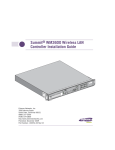
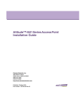
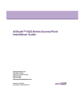
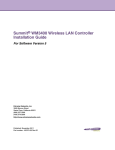
Altitude™ 3550 Access Point Deployment Guide
Extreme Networks, Inc.
3585 Monroe Street
Santa Clara, California 95051
(888) 257-3000
(408) 579-2800
http://www.extremenetworks.com
Published: December 2009
Part Number: 100351-00 Rev 01
AccessAdapt, Alpine, Altitude, BlackDiamond, EPICenter, ExtremeWorks Essentials, Ethernet Everywhere, Extreme
Enabled, Extreme Ethernet Everywhere, Extreme Networks, Extreme Standby Router Protocol, Extreme Turbodrive,
Extreme Velocity, ExtremeWare, ExtremeWorks, ExtremeXOS, Go Purple Extreme Solution, ExtremeXOS
ScreenPlay, ReachNXT, Sentriant, ServiceWatch, Summit, SummitStack, Triumph, Unified Access Architecture,
Unified Access RF Manager, UniStack, the Extreme Networks logo, the Alpine logo, the BlackDiamond logo, the
Extreme Turbodrive logo, the Summit logos, and the Powered by ExtremeXOS logo are trademarks or registered
trademarks of Extreme Networks, Inc. or its subsidiaries in the United States and/or other countries.
sFlow is a registered trademark of InMon Corporation.
Specifications are subject to change without notice.
All other registered trademarks, trademarks, and service marks are property of their respective owners.
© 2009 Extreme Networks, Inc. All Rights Reserved.
2
Altitude 3550 Access Point Deployment Guide
Table of Contents
Chapter 1: About This Guide ..................................................................................................................... 5
Introduction..............................................................................................................................................................5
Document Conventions............................................................................................................................................5
Notational Conventions ...........................................................................................................................................5
Chapter 2: Introduction .............................................................................................................................. 7
Chapter 3: Mounting Kit Assembly and Use ............................................................................................ 9
Installing the AP3550’s Mounting Accessories.......................................................................................................9
Installing the AP3550 to a Pole .............................................................................................................................11
Chapter 4: Heavy Weather Kit Assembly and Use ................................................................................ 17
Chapter 5: Power Tap Installation .......................................................................................................... 21
Pre-Installation Guidelines ....................................................................................................................................21
Power Tap Installation ...........................................................................................................................................21
Chapter 6: Cable Connectors and Unused Connector Protection ........................................................ 27
Chapter 7: Customer Support.................................................................................................................. 31
Registration ............................................................................................................................................................31
Documentation.......................................................................................................................................................31
Altitude 3550 Access Point Deployment Guide
3
Table of Contents
4
Altitude 3550 Access Point Deployment Guide
1
About This Guide
Introduction
This guide provides detailed hardware setup and deployment instructions for the Extreme Networks®
Altitude™ 3550 (AP3550) model access point. The AP3550 model access point is primarily designed for
outdoor deployments, thus it has a unique set of installation instructions.
Document Conventions
The following document conventions are used in this document:
NOTE
Indicate tips or special requirements.
CAUTION
Indicates conditions that can cause equipment damage or data loss.
WARNING!
Indicates a condition or procedure that could result in personal injury or equipment damage.
Notational Conventions
The following notational conventions are used in this document:
●
Italics are used to highlight specific items in the general text, and to identify chapters and sections in
this and related documents.
●
Bullets (•) indicate:
●
●
action items
●
lists of alternatives
●
lists of required steps that are not necessarily sequential
Sequential lists (those describing step-by-step procedures) appear as numbered lists.
Altitude 3550 Access Point Deployment Guide
5
About This Guide
6
Altitude 3550 Access Point Deployment Guide
2
Introduction
Please review all the material within this document before installing the AP3550 model access point.
The purpose of this guide is to assist you in understanding the correct use and placement of the
components within the AP3550 accessory kits. Proper installation is critical to the safety of the
installation, installer and others in the area of the AP3550’s deployment.
To deploy your AP3550 model access point in an outdoor environment, refer to the following:
●
“Mounting Kit Assembly and Use”
●
“Heavy Weather Kit Assembly and Use”
●
“Power Tap Installation”
●
“Cable Connectors and Unused Connector Protection”
Altitude 3550 Access Point Deployment Guide
7
Introduction
8
Altitude 3550 Access Point Deployment Guide
3
Mounting Kit Assembly and Use
It is recommended the assembly of the AP3550’s accessories be started, and fully staged (as described in
this chapter) before the AP3550 is moved into its final area of deployment.
Installing the AP3550’s Mounting Accessories
To install the AP3550’s mounting accessories:
1 Install the mounting bracket to the AP3550’s rear housing using 4 short length binder head screws
from the kit. Tighten securely.
NOTE
Take note of the earth ground boss under the bracket. This point must be properly grounded to earth to utilize
this products safety features. This is a good time to add the required grounding lug or cable (not included with
the AP3550 or mounting kit).
2 Install the AP3550 tilt bracket onto the AP3550’s bracket installed in step 1.
Use one long binder head screw and hex nut from the kit. This will define the pivot about which the
AP3550 can be tilted. Do not over tighten the nut.
Altitude 3550 Access Point Deployment Guide
9
Mounting Kit Assembly and Use
3 Install 4 short binder head screws in the 4 slots, 2 each on left and right sides of the tilt bracket.
These can be tightened during this phase of the assembly. Once deployed in the field, the 4 screws
should be loosened slightly to allow the AP3550 to be tilted to level, then re-tightened.
4 If sliding to a small pole diameter, up to 2 ½ inches in diameter, place the pole clamps into the slots
of the bracket assembled in step 3.
The pole clamps can be installed into inner or outer slots to adjust for pole diameters of various
sizes.
5 Install 2 long binder head screws through the two holes of one clamp into the other clamp. Direction
is not important.
10
Altitude 3550 Access Point Deployment Guide
On each long screw, install one split washer and one wing nut. Leave them somewhat loose, as the
nut, washer and screw will be loosened and re-installed in the field when mounting the AP3550 to a
Pole.
NOTE
The unit is ready to be moved into its deployment area and mounted onto a pole (where the AP3550 cannot be
slid over the pole end).
Installing the AP3550 to a Pole
To install an AP3550 to a pole:
1 Select the proper slot positions for the pole clamp to properly fit onto the pole. Position and hold the
tilt bracket. Align each of the 2 pole clamps in position on the pole. Install 2 long binder head screws
through the two holes of one clamp and into the other clamp. Direction is not important.
Install one split washer and one wing nut onto each long screw. Lightly tighten the wing nut,
washer and screw.
Point the tilt bracket in the direction the AP3550 is to be mounted, and tighten the wing nut, washer
and screw
Altitude 3550 Access Point Deployment Guide
11
Mounting Kit Assembly and Use
2 Install the mounting bracket onto the tilt bracket installed in step 1. Use one long binder head screw
and hex nut from the kit. This will provide the pivot about which the AP3550 can be tilted. Do not
over tighten the nut.
3 Install 4 short binder head screws in the 4 slots (two each on left and right sides of the tilt bracket).
Set the angle of the AP3550 up or down as required for the installation. The 4 short binder head
screws and the long screw hex nut can all be tightened to lock the unit into position.
The image displayed above has the heavy weather accessory kit installed. Whether the unit is
installed with the heavy weather kit, or without it, it will be important to connect the AP3550 to an
appropriate earth ground using the earth-ground boss on the back of the unit.
NOTE
It is necessary to use the band clamp adapter when installing an AP3550 on a larger diameter pole (up to 18
inches).
12
Altitude 3550 Access Point Deployment Guide
4 Thread the 2 band clamps through the adapter.
Using both band clamps, position the adjuster screw about 6 inches from the face of the adapter. The
adjuster screw can be installed to either left or right sides.
5 Mount the adapter to the tilt bracket using 2 short binder head screws. It does not matter which side
is up or down, left or right. Tighten the screws securely.
6 Position and hold the tilt bracket and each of the band clamps onto the mounting pole. Thread the
band clamp through its own adjuster screw. Ensure the band clamp is installed into it’s own adjust
screw.
Altitude 3550 Access Point Deployment Guide
13
Mounting Kit Assembly and Use
Thread the free end of the band clamp through the adjuster. Pass through the screw, and pull the
free end of the clamp until it is snug. Repeat this process for the second clamp.
Point the tilt bracket in the direction the AP3550 is to be mounted. Tighten the band clamps. Cut off
or wrap around (as displayed above) the free end of the tightened band clamp.
7 Install the AP3550’s mounting bracket onto the tilt bracket. Use one long binder head screw and hex
nut from the kit. This will provide the pivot about which the AP3550 can be tilted. Do not over
tighten the nut.
The image displayed has the heavy weather accessory kit installed. Whether the unit uses the heavy
weather kit or not, remember to connect the AP3550 to an appropriate earth ground using the earthground boss on the back of the unit.
14
Altitude 3550 Access Point Deployment Guide
8 Install 4 short binder head screws in the 4 slots (2 each on left and right sides of the tilt bracket). Set
the angle of the AP3550 up or down as required for the installation. The 4 short binder head screws,
and the long screw hex nut can be tightened to lock the AP3550 into position.
Altitude 3550 Access Point Deployment Guide
15
Mounting Kit Assembly and Use
16
Altitude 3550 Access Point Deployment Guide
4
Heavy Weather Kit Assembly and Use
NOTE
It is recommended that assembly of the AP3550 heavy weather kit be started, and fully staged, before the unit
is moved into the field for deployment.
To install the AP3550 heavy weather kit:
1 Install 4 antenna extension cables (provided in the kit) to the AP3550. Hand tighten.
Altitude 3550 Access Point Deployment Guide
17
Heavy Weather Kit Assembly and Use
2 Route the antenna extension cables through the cable guides on the rear of the access point. The
cables cross from left to right to maximize the bend radius. Avoid any sharp bending of the cables to
extend their useful life.
NOTE
Note the earth ground boss on the AP3550. This point must be properly grounded to earth to utilize this products
safety features. This is a good time to add the required grounding lug or cable (not included).
3 Install the heavy weather shield. Align the 4 screw holes with the 4 mating screw bosses on the
AP3550.
18
Altitude 3550 Access Point Deployment Guide
4 Install the mounting bracket to the AP3550’s rear housing using 4 short length binder head screws
from kit.
The heavy weather shield is clamped between the bracket and the housing. Tighten securely.
5 Turn the unit over. On the face of the unit, remove and discard the 4 screws located in the cover of
the AP3550.
6 Install 4 hex stand-off screws into the screw holes created with the removal of the screws in step 5.
Tighten securely.
Altitude 3550 Access Point Deployment Guide
19
Heavy Weather Kit Assembly and Use
7 Install the heavy weather shield.
Align the 4 screw holes with the 4 mating screw bosses on the AP3550 cover.
8 Install the AP3550 mounting bracket to AP3550 cover using 4 short length binder head screws from
the kit. The front and rear shields are intentionally staggered to ensure adequate ventilation.
9 The heavy weather protected AP3550 is now ready for installation.
20
Altitude 3550 Access Point Deployment Guide
5
Power Tap Installation
The installation of the AP3550 Power Tap (Part No. 15729) requires the services of licensed and trained
electricians. The end user is solely responsible to ensure the unit is installed and maintained by
properly certified personnel. Additionally, the end user is responsible the unit is installed and
maintained in full compliance of local codes and standards.
WARNING!
DO NOT open an installed or operating Power Tap unit. Always make sure the unit is not energized before opening
an installed or operating unit.
Pre-Installation Guidelines
Before attempting to install a Power Tap, refer to the following guidelines:
●
DO NOT open an installed or operating unit. Ensure the unit is not energized before opening an
installed or functioning unit.
●
A Power Tap installation requires the services of licensed and trained electrician.
●
Proper unit earth grounding is required to ensure safe and proper operation. Earth grounding must
comply with all specific or regional electrical codes and regulations.
●
Opening the Power Tap exposes high voltage wiring, and creates a shock hazard. Care must be
taken to avoid introduction to the unit interior of any foreign object and/or fluids that would
facilitate a shock hazard.
●
The instructions provided herein are intended to provide useful installation guidance, and offer
insight into best practices. Adherence to this guide, and the instructions herein do not ensure
compliance with specific or regional electrical codes and regulations.
●
In all cases, specific or regional electrical codes and regulations shall govern the installation of this
product.
●
Installation and maintenance of this product in compliance with specific or regional electrical codes
and regulations is the sole responsibility of the end user.
Power Tap Installation
Before installing the Power Tap, ensure your have familiarized yourself with the pre-installation
guidelines described in “Pre-Installation Guidelines” on page 21.
Altitude 3550 Access Point Deployment Guide
21
Power Tap Installation
To install an AP3550 Power Tap:
1 Remove and retain the 10 screws used to secure the Power Tap cover.
2 Remove the weather sealing cover to expose the unit’s interior. Do not remove or tamper with the
sealing gasket remaining on the back housing.
3 Remove and retain the 2 terminal screws releasing the 2 solder-less ring terminals.
4 Remove and retain the nut with a captive locking washer. This nut releases a solder-less ring
terminal.
22
Altitude 3550 Access Point Deployment Guide
5 Loosen the gland nut on the power entry fitting.
6 Expose 6 inches of wire from the jacket. Only use wire suited for your specific installation
requirements and application.
Use 3 conductor wire of a gage suitable for the required wire run.
7 Feed the wire through the power fitting. Do not tighten the fitting at this time.
8 Using the solder-less ring terminals, strip and terminate the individual wires.
Expose only sufficient copper (using a solder-less terminal crimping tool) to ensure a good electrical
connection. No exposed copper strands should be visible outside the terminal insulator.
Altitude 3550 Access Point Deployment Guide
23
Power Tap Installation
9 Install the power cable ring terminals using the 2 screws and nut removed in steps 3 and 4.
●
Black wire to terminal L (line)
●
White wire to terminal N (neutral)
●
Green wire to terminal G (ground)
10 Firmly tighten screws and nut.
11 Adjust the cable jacket by sliding into and out of the gland until about 1 inch remains visible inside
the housing.
Tighten the gland nut by hand to firmly hold the cable jacket. Examine all wires to ensure there is no
crimping pulling of wires or terminations.
24
Altitude 3550 Access Point Deployment Guide
12 Ensure no loose hardware is inside the housing. Check the wiring to be sure it is clear of the cover.
Carefully replace the cover. Only the correct cover orientation (as displayed below) allows all screws
to be properly installed.
Tighten all 10 screws securely.
The Power Tap can now be installed in an almost identical manner as the AP3550 model access
point following the instructions within “Mounting Kit Assembly and Use” on page 9.
NOTE
Please locate the earth ground boss under the bracket of the Power Tap. This point must be properly grounded to
earth to utilize this product’s safety features.
13 Add the required grounding lug or cable (not included with this product) the earth ground boss.
14 Seal un-used connectors to ensure the product’s IP56 rating.
Altitude 3550 Access Point Deployment Guide
25
Power Tap Installation
Locate a port cover within the Part No. 15729 product package. Install the cover on the unused LAN
or WAN port and hand tighten (do not use tools).
For installations connecting to the Power Tap’s “DATA IN” and “DATA PWR OUT” ports, refer to
“Cable Connectors and Unused Connector Protection” on page 27.
NOTE
Locate the earth ground boss on the back of the Power Tap. This point must be properly grounded to earth to
utilize this product’s safety features. If you have not already done so, this is a good time to add the required
grounding lug or cable.
The Power Tap can be installed using the standard AP3550 mounting kit. The Power Tap can be
installed using the integrated mounting holes. The 2 holes are provided at the top and bottom of the
unit.
Proper mounting of the unit places the 10 screw-heads against the mounting surface, thus making
un-authorized installations difficult.
When mounting the Power Tap on materials such as concrete or plaster, the use of wall anchors will
provide an excellent holding grip. Use the Power Tap’s 2 mounting holes as a template and punch
or drill holes to accept the 2 wall anchors.
26
Altitude 3550 Access Point Deployment Guide
6
Cable Connectors and Unused Connector
Protection
The following figure shows the various components found in the connector kit supplied with the
AP3550. If a different connector is used (or the connector is replaced), the replacement must be IP56
certified to retain product sealing.
The cable shown in the figure is customer provided and must be of the length required for your specific
AP3550 deployment. The cable must be rated for outdoor use and have 8 conductors. Shielding is not
required for the cable used.
To install the AP3550 cabling:
1 Install the silicone rubber gland into the gland housing.
Altitude 3550 Access Point Deployment Guide
27
Cable Connectors and Unused Connector Protection
2 Loosely assemble the gland nut onto the gland housing. Do not tighten until the connector is fully
assembled and installed into the desired AP3550 connection port.
This step creates the gland assembly.
3 Install the ring seal onto the end of the flange barrel. A small amount of grease on the surfaces will
hold the ring in place for the remainder of the assembly.
As an option (and not displayed above), the ring seal can be inserted into the receiving threaded
hole of the gland housing. The receiving threaded hole is in the hexagonal section of the gland
housing stamped with “LTW” (see the illustration with step 2). Ensure the ring seal is seated at the
bottom of the threaded hole.
4 Assemble the gland assembly, finger nut, flange barrel and modular connector onto the cable.
NOTE
The modular connector is intended to be wired specifically. It is extremely important to wire the connector per
industry standards for Ethernet, non-cross-over configuration). The applicable standard is TIA/EIA 568-A.
You are now ready to install the connector face gasket.
28
Altitude 3550 Access Point Deployment Guide
5 Remove the adhesive liner on the gasket (refer to the illustration on the previous page for an
example). Slide the gasket over the connector and along the cable, with the adhesive facing the
flange surface of the flange barrel.
Press the gasket into place on the plastic face with light finger pressure. Make sure the cut-out of the
gasket aligns with the shape of the connector pocket of the flange barrel.
6 Slide the flange barrel so the modular connector is fully seated into the connector pocket.
Depress the modular connector latch spring against the body of the connector to fit the connector
into the pocket.
7 Insert the connector into the LAN or WAN port of the AP3550. The connector will only plug into the
port if the connector is properly orientated. Using only finger pressure, no tools.
Tighten the finger nut snugly onto the port. Next, tighten the gland assembly onto the flange barrel.
Finally, tighten the gland nut onto the gland assembly. When completed, the assembly will be
weather resistant to IP56, and offer reasonable strain relief to the cable.
Altitude 3550 Access Point Deployment Guide
29
Cable Connectors and Unused Connector Protection
NOTE
Un-used connectors need to be sealed to ensure the product’s IP56 rating.
8 Locate 2 port covers, and 3 antenna connection covers within the access point (AP3550-US Part
Number 15722; AP3550-ROW Part Number 15726) product package.
9 Install the covers on any un-used ports and hand tighten (use no tools).
Please note the earth ground boss on the back of the unit. This point must be properly grounded to
earth to utilize the AP3550’s safety features. Add the required grounding lug or cable (not included
with the AP3550) at this time.
30
Altitude 3550 Access Point Deployment Guide
7
Customer Support
NOTE
Services can be purchased from Extreme Networks or through one of its channel partners. If you are an end-user
who has purchased service through an Extreme Networks channel partner, please contact your partner first for
support.
Extreme Networks Technical Assistance Centers (TAC) provide 24x7x365 worldwide coverage. These centers are
the focal point of contact for post-sales technical and network-related questions or issues. TAC will create a
Service Request (SR) number and manage all aspects of the SR until it is resolved. For a complete guide to
customer support, see the Technical Assistance Center User Guide at:
http://www.extremenetworks.com/go/TACUserGuide
The Extreme Networks eSupport website provides the latest information on Extreme Networks
products, including the latest Release Notes, troubleshooting, downloadable updates or patches as
appropriate, and other useful information and resources. Directions for contacting the Extreme
Networks Technical Assistance Centers are also available from the eSupport website at:
https://esupport.extremenetworks.com
Registration
If you have not already registered with Extreme Networks using a registration card supplied with your
product, you can register on the Extreme Networks website at:
http://www.extremenetworks.com/go/productregistration.
Documentation
Check for the latest versions of documentation on the Extreme Networks documentation website at:
http://www.extremenetworks.com/go/documentation
Altitude 3550 Access Point Deployment Guide
31