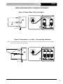
1
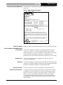
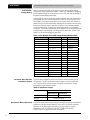
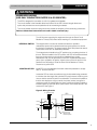
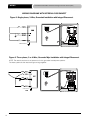
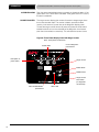
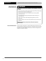
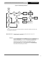
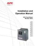
Surge Protective Devices (SPD)
APC Modular Panel Products
Installation and Operation Manual
The APC Modular Panel Product Surge Protective Devices (SPD)
are designed to provide protection at the service entrance, branch
panels or other critical locations for today’s electrical equipment.
The APC SurgeArrest® Modular Panel Mount Products have
replaceable phase modules with integrated LED monitoring, a
display panel with surge counter and LED status indicators, an
audible alarm, and a NEMA 3R/12 Enclosure. Modular Panel
Products are available with 120kA and 160kA maximum surge
current per phase ratings.
PMF3S-A
PMF3DS-A
PMF4S-A
PMF4DS-A
PMG3S-A
PMG3DS-A
Compliant with UL 1449 2nd Edition requirements
dated February 9, 2007.
PMG4S-A
PMG4DS-A
PMH4DSLM-A
PML3S-A
PML3DS-A
PML4S-A
PML4DS-A
PML-4Y-DC-DL-A
PMP3S-A
PMP3DS-A
PMP4S-A
PMP4DS-A
Retain for future use
1-800-800-4272 | www.apc.com
WARNINGS
APC MODULAR PANEL PRODUCTS Surge Protective Device (SPD)
DANGER
HAZARD OF ELECTRIC SHOCK, EXPLOSION, OR ARC FLASH
· Apply appropriate personal protective equipment (PPE) and follow safe electrical work practices.
See NFPA 70E.
· This equipment must only be installed and serviced by qualified electrical personnel.
· Turn off all power supplying this equipment before working on or inside equipment.
· Always use a properly rated voltage sensing device to confirm power is off.
· Replace all devices, doors and covers before turning on power to this equipment.
Failure to follow these instructions will result in death or serious injury.
CAUTION
LOSS OF BRANCH CIRCUIT POWER AND SURGE PROTECTION
In the event that the surge protective elements of the SPD have been damaged (i.e. excessive surge
energy, power system anomaly, etc.), the surge protective elements can lose their ability to block
power system voltage and attempt to draw excessive current from the line. This SPD is equipped with
overcurrent and overtemperature protection that will automatically disconnect the surge protective
elements from the mains should the surge protective elements be damaged.
The effects of damaged surge protective elements and the subsequent operation of the automatic
overcurrent and overtemperature protection must be considered when applying a SPD, particularly
when critical loads requiring continuity of power or continuity of surge protection are present on the
power system. The following items should be considered when applying a SPD:
· Tripping of the branch circuit breaker feeding the SPD can occur when the surge protective
elements are damaged. Do not connect the SPD to a branch circuit feeding a load requiring
continuity of power (i.e. central computer or control systems, safety-critical equipment, critical
processes or systems, etc.) unless the branch circuit breaker trip characteristic has been
coordinated with the overcurrent protection inside the SPD.
· Periodic inspection of the state of the status indicator lights on the SPD should be made as part of
the preventive maintenance schedule. The SPD should be promptly serviced when an alarm
state exists.
· For unmanned, inaccessible, or critical installations, the dry contacts should be used to signal an
alarm state to the central supervisory system.
· In addition to the preceding items, the use of multiple SPD’s to achieve redundancy should be
considered for critical applications.
Failure to follow these instructions can result in loss of power or loss of surge protection
that can cause injury or equipment damage.
2
APC MODULAR PANEL PRODUCTS Surge Protective Device (SPD)
WARNINGS
CAUTION
LOSS OF SURGE PROTECTION
· During installation into an electrical system, SPD’s must not be energized until the electrical system
is completely installed, inspected, and tested. All conductors must be connected and functional,
including the neutral. The voltage rating of the device and system must always be verified before
energizing the surge protective device.
· Any factory or on-site testing of power distribution equipment that exceeds the normal operating
voltage, such as high-potential insulation testing, or any other tests where the suppression
components will be subjected to voltages higher than their rated turn-on voltage must be performed
with the suppressor disconnected from the power source. The neutral connection at the SPD must
also be disconnected prior to performing high-potential testing and then reconnected upon
completion of the test.
Failure to follow these instructions can result in loss of power or loss of surge protection
that can cause injury or equipment damage.
IMPORTANT!
Electrical equipment should be installed, operated, serviced, and maintained only by qualified
personnel. No responsibility is assumed by APC for any consequences arising out of the use of
this material.
3
TABLE OF CONTENTS
APC MODULAR PANEL PRODUCTS Surge Protective Device (SPD)
SurgeArrest® Modular PM Series
CONTENTS
INTRODUCTION .............................................................................. 5
UNPACKING AND PRELIMINARY INSPECTION ............................... 6
STORAGE ........................................................................................ 6
IDENTIFICATION NAMEPLATE ......................................................... 7
SAFETY LABELS ............................................................................. 7
SPD LOCATION CONSIDERATIONS ................................................ 7
Environment .............................................................................. 7
Audible Noise............................................................................. 7
Mounting ................................................................................... 7
Service Clearance ...................................................................... 7
Equipment Performance ............................................................ 7
ELECTRICAL ................................................................................... 8
Service Voltage / Model Numbers ............................................ 8
Terminals, Wire Size and Installation Torque ............................. 9
Disconnect Means ................................................................... 9
Integral Disconnect ..................................................................10
Location of SPD ......................................................................10
SYSTEM GROUNDING ....................................................................10
INSTALLATION ............................................................................... 11
Conduit Location and Recommendations .................................11
Special Enclosure Considerations ............................................ 11
Removing and Reconnecting the Patch Cables ........................ 11
NEMA 3R Applications ............................................................ 11
WIRING ........................................................................................12
Wiring Diagrams without Integral Disconnect ............................13
Wiring Diagrams with Integral Disconnect ................................ 14
OPERATION ...................................................................................15
LED Status Indicators ..............................................................15
Audible Alarm ..........................................................................16
Surge Counter ........................................................................16
Dry Contacts ...........................................................................17
Remote Monitor Option ........................................................... 17
MAINTENANCE AND TROUBLESHOOTING ................................... 18
Preventive Maintenance .......................................................... 18
Troubleshooting ....................................................................... 19
Replacement Parts .................................................................. 19
WARRANTY.................................................................................... 19
CUSTOMER SUPPORT.................................................................. 20
4
APC MODULAR PANEL PRODUCTS Surge Protective Device (SPD)
INTRODUCTION
INTRODUCTION
Thank you for choosing the APC SurgeArrest® PM3 or PM4 Series Surge Protection Device.
The APC modular Surge Protection Device (SPD) is a high-quality, high-energy surge attenuation system
that has been designed to protect sensitive equipment from damaging transient voltage surges. Proper
installation is imperative to maximize the surge suppressor’s effectiveness and performance.
This manual is to be used as a guide for installing the device. Read and understand all information
contained in this manual prior to installation. The outlined procedures are not intended to supersede local or
national electrical codes. Check all applicable electrical codes to assure compliance.
This device must be installed by a licensed electrician. The electrician should follow the steps detailed in
this manual to ensure proper installation. A copy of the installer’s invoice, detailing the installation of
this device, is required in order to take advantage of the unit’s product warranty.
The SurgeArrest® PM3 and PM4 Series modular product lines specify a parallel SPD designed for service
entrance and downstream panelboard applications. These units provide replaceable module surge protection
and are available with 120kA and 160kA per phase ratings, respectively.
All APC products are extensively tested according to industry standards as set by IEEE C62.41 and C62.45
for Categories A, B, and C. The connection method for these devices may require several feet of wire. Be
aware that increased lead length adversely affects clamping voltages.
Save this manual! It includes instructions regarding the product warranty and replacement parts.
Testing
Any factory or on-site testing that exceeds the normal operating voltage, such as high-potential insulation
testing or other tests where the suppression components will be subjected to voltages higher than their rated
"turn on" voltage, must be run with the suppressor disconnected from the power source. For 4-wire TVSS
devices, the neutral connection at the TVSS must also be disconnected prior to performing high-potential
testing and then reconnected upon completion of the test.
Failure to disconnect this surge suppression device and its associated suppression components during
elevated voltage testing will result in damage to the suppression components and/or other electronic
components.
5
PACKAGING
APC MODULAR PANEL PRODUCTS Surge Protective Device (SPD)
DANGER
HAZARD OF ELECTRIC SHOCK, EXPLOSION, OR ARC
FLASH
· Apply appropriate personal protective equipment (PPE) and follow safe
electrical work practices. See NFPA 70E.
· This equipment must only be installed and serviced by qualified
electrical personnel.
· Turn off all power supplying this equipment before working on or
inside equipment.
· Always use a properly rated voltage sensing device to confirm
power is off.
· Replace all devices, doors and covers before turning on power to this
equipment.
Failure to follow these instructions will result in death or
serious injury.
UNPACKING AND
PRELIMINARY INSPECTION
Proper installation is imperative to maximize the APC Modular Panel SPD’s
effectiveness and performance. The installer should follow the steps outlined
in this instruction manual to ensure proper installation. Read the entire
instruction manual before beginning the installation. These instructions are
not intended to replace national or local electrical codes. Check all applicable
electrical codes to verify compliance. Installation of surge suppressors should
only be performed by qualified electrical personnel.
NOTE: SPD 's are designed for use on the load side of the service entrance
disconnect only.
Inspect the entire shipping container for damage or signs of mishandling
before unpacking the device. Remove the packing material and further
inspect the device for any obvious shipping damage. If any damage is
found and is a result of shipping or handling, immediately file a claim with
the shipping company.
STORAGE
6
The device should be stored in a clean, dry environment. Storage
temperature is -40 to +65 °C (-40 to +149 °F). All of the packaging
materials should be left intact until the device is ready for installation.
APC MODULAR PANEL PRODUCTS Surge Protective Device (SPD)
IDENTIFICATION NAMEPLATE
IDENTIFICATION
The identification nameplate (see Figure 1) is located on the inside of the
door/cover.
Figure 1: SPD Nameplate Example
SAFETY LABELS
English versions of all safety labels (danger, warning, caution) are provided.
SPD LOCATION CONSIDERATIONS
Environment
Audible Noise
Mounting
Service Clearance
Equipment Performance
The device is designed to operate in an ambient temperature range of
-40 to +65 °C (-40 to +149 °F) with a relative humidity of 0 to 95% noncondensing. Refer to the product catalog for further details on enclosures.
All SPD’s operate normally without reduction in performance when
subjected to shock and vibrations described in IEC 60721-3-3, Class 3M4.
The device background noise is negligible and does not restrict the
location of the installation.
This device is designed to be surface mounted. Refer to the device submittal
drawings or the product catalog for typical mounting dimensions and weight.
Install the APC Modular Panel SPD in a restricted access area.
The service clearance should meet all applicable code requirements.
To obtain the maximum system performance, locate the device as close
as possible to the circuit breaker to minimize the interconnecting wiring
length. For every foot in length of wire, approximately 175 volts per foot
(6 kV/ 3 kA, 8/20 microsecond) is added to the suppressed voltage.
The suppressed voltage rating is located on the device nameplate and
is measured 6 inches from the device terminals, according to UL® 1449
Second Edition.
7
ELECTRICAL
APC MODULAR PANEL PRODUCTS Surge Protective Device (SPD)
ELECTRICAL
Voltage Rating
Prior to mounting the SPD, verify that the device has the same voltage
rating as the power distribution system in which it is installed by comparing
the nameplate voltage or model number on the SPD with the nameplate of
the electrical distribution equipment.
The specifier or user of the device should be familiar with the configuration
and arrangement of the power distribution system in which any SPD is to
be installed. The system configuration of any power distribution system is
based strictly on how the secondary windings of the transformer supplying
the service entrance main or load are configured. This includes whether
or not the transformer windings are referenced to earth via a grounding
conductor. The system configuration is not based on how any specific load
or equipment is connected to a particular power distribution system. See
Table 1 for the service voltage of each SPD.
Table 1: APC Modular Panel SPD Voltage Ratings/Model Number
Service voltage
configuration
120/208 wye
3Ph. Wye 4-wire +G
120kA
PMF3S-A
120/208 wye
3Ph. Wye 4-wire +G
120kA
PMF3DS-A
120/240 wye (Single Phase)
1Ph. Wye 3-wire +G
120kA
PMP3S-A
120/240 wye (Single Phase)
1Ph. Wye 3-wire +G
120kA
PMP3DS-A
277/480 wye
3Ph. Wye 4-wire +G
120kA
PMG3S-A
ka rating
MoDel nuMBer
277/480 wye
3Ph. Wye 4-wire +G
120kA
PMG3DS-A
347/600 wye
3Ph. Wye 4-wire +G
120kA
PML3S-A
347/600 wye
3Ph. Wye 4-wire +G
120kA
PML3DS-A
120/208 wye
3Ph. Wye 4-wire +G
160kA
PMF4S-A
120/208 wye
3Ph. Wye 4-wire +G
160kA
PMF4DS-A
120/240 wye (Single Phase)
1Ph. Wye 3-wire +G
160kA
PMP4S-A
120/240 wye (Single Phase)
1Ph. Wye 3-wire +G
160kA
PMP4DS-A
220/380 wye
3Ph. Wye 4-wire +G
160kA
PMH4DSLM-A
277/480 wye
3Ph. Wye 4-wire +G
160kA
PMG4S-A
277/480 wye
3Ph. Wye 4-wire +G
160kA
PMG4DS-A
347/600 wye
3Ph. Wye 4-wire +G
160kA
PML4S-A
347/600 wye
3Ph. Wye 4-wire +G
160kA
PML4DS-A
347/600 wye
3Ph. Wye 4-wire +G
160kA
* PML-4Y-DC-DL-A
* Redundant 160kA system
Terminals, Wire Size and
Installation Torque
Terminals are provided for phase (line), neutral, and equipment ground
connections. The SPD terminals accept a range of #12 to #2 AWG (34
mm2) copper wire for phase, neutral, and ground connectors. Torque
connections to the following values.
Table 2: Installation Torque
Power Connection
AØ, BØ, CØ & N
Ground
Disconnect Means (External)
8
Terminal Torque
W/O Disconnect
W/ Disconnect
35 lb-in (4N·M)
50 lb-in (5.7N·M)
50 lb-in (5.7N·M)
The use of fusible disconnects requires a fuse with a melting characteristic
greater than the per phase (Clearing) I2t of the SPD to prevent nuisance
operation of the disconnect fuses during a surge. (Refer to caution
statement “LOSS OF BRANCH CIRCUIT POWER AND SURGE
PROTECTION” on page 2 for further information)
ELECTRICAL
APC MODULAR PANEL PRODUCTS Surge Protective Device (SPD)
WARNING
UNDERSIZED WIRING
(USE ONLY CONDUCTORS RATED 30 A OR GREATER.)
· The SPD is designed for connection to a 30 A (or greater) circuit breaker.
· The circuit breaker is the intended disconnect means for the SPD without integral disconnect
option and provides over current protection for the connecting conductors.
· The circuit breaker maximum rating should not exceed the ampacity of the connecting conductors.
Failure to follow these instructions can result in death or serious injury.
Turn off all power supplying this equipment through the Panel Circuit
Breaker or Primary Disconnect before working on or inside the equipment.
INTEGRAL SWITCH
The integral switch is a second mechanical means for qualified
maintenance personnel to isolate the entire surge suppressor to service
the device’s components. The integral switch opens the phase and neutral
connections to the SPD for additional protection.
Turn integral switch handle to the OFF position prior to opening the door of
the unit. With the handle in the OFF position, the SPD will be disconnected
from the circuit and the circuit will not be protected from surges.
Maintenance may now be performed on the SPD modules and associated
parts. Upon completion of repairs, close the door of the unit and turn the
handle to the ON position. Close the Panel Circuit Breaker or Primary
Disconnect to power SPD.
LOCATION OF SPD
Install SPD’s on the load side of the main overcurrent protection to comply
with UL 1449 and the NEC.
Locate the SPD as close as possible to the circuit breaker being protected
to minimize the wire length and optimize SPD performance. Avoid long wire
runs so that the device will perform as intended. To reduce the impedance
that the wire displays to surge currents, the phase, neutral, and ground
conductors must be routed within the same conduit and tightly bundled or
twisted together to optimize device performance. Avoid sharp bends in the
conductors. See Figure 2.
Figure 2: Wiring Practice
To "protected" load(s)
SPD
Phase A
Phase B
Phases
Neutral
Ground
Phase C
Neutral bus
Ground bus
Neutral
Ground
Interconnect wiring
- Minimize length
- Avoid sharp bends
9
ELECTRICAL
SYSTEM GROUNDING
APC MODULAR PANEL PRODUCTS Surge Protective Device (SPD)
CAUTION
SYSTEM GROUNDING
· SPD must be installed on solidly grounded power systems.
· Verify that the service entrance equipment is bonded to ground in
accordance with all applicable codes.
· Verify that the neutral terminals are grounded to system ground in
accordance with all applicable codes.
Failure to follow these instructions can result in equipment
damage.
An equipment ground conductor must be used on all electrical circuits
connected to the SPD. For the best performance, use a single-point
ground system where the service entrance grounding electrode system
is connected to and bonded to all other available electrodes, building
steel, metal water pipes, driven rods, etc. (for reference, see IEEE STD
142-1991). The ground impedance measurement of the electrical system
should be as low as possible, and in compliance with all applicable
codes, for electronics and computer systems.
When metallic raceway is used as an additional grounding conductor,
an insulated grounding conductor should be run inside the raceway and
sized in accordance with all applicable codes.
WARNING
INADEQUATE RACEWAY ELECTRICAL CONTINUITY
· Ground impedance must be as low as possible and in compliance with
all applicable codes for electronic and computer systems.
· Install an insulated grounding conductor inside a metallic raceway when
the raceway is used as an additional grounding conductor. Size the
conductor in accordance with all applicable codes.
· Maintain adequate electrical continuity at all raceway connections.
· Do not use isolating bushings to interrupt a metallic raceway run.
· Do not use a separate isolated ground for the SPD.
· Verify proper equipment connections to the grounding system.
· Verify ground grid continuity by inspections and testing as part of a
comprehensive electrical maintenance program.
Failure to follow these instructions can result in death or
serious injury.
10
APC MODULAR PANEL PRODUCTS Surge Protective Device (SPD)
INSTALLATION
INSTALLATION
DANGER
HAZARD OF ELECTRIC SHOCK, EXPLOSION, OR ARC
FLASH
· Apply appropriate personal protective equipment (PPE) and follow safe
electrical work practices. See NFPA 70E.
· This equipment must only be installed and serviced by qualified
electrical personnel.
· Turn off all power supplying this equipment before working on or
inside equipment.
· Always use a properly rated voltage sensing device to confirm
power is off.
· Replace all devices, doors and covers before turning on power to this
equipment.
Failure to follow these instructions will result in death or
serious injury.
CONDUIT LOCATION AND
RECOMMENDATIONS
The recommended conduit entry is at the bottom of the device enclosure.
Use a conduit seal that is appropriate for the enclosure rating.
SPECIAL ENCLOSURE
CONSIDERATIONS
Removing and Reconnecting
the Communication
Patch Cables
The communication patch cables are marked with matching phase
connections. If any of the cables are removed, reconnect the cables as
marked.
NEMA 3R Applications
Remove screws from the bottom of the enclosure to create drain holes.
Mounting Recommendation
Locate the SPD as close as physically possible to the node/equipment to
be protected, thereby limiting lead length and ensuring lower let through
voltages on the protected equipment. For every foot of wire length,
approximately 1 nanosecond of turn-on/turn-off time will be added, and
approximately 175 volts (6kV/3kA,8/20 microseconds) will be added to the
clamping voltage.
11
WIRING
APC MODULAR PANEL PRODUCTS Surge Protective Device (SPD)
DANGER
HAZARD OF ELECTRIC SHOCK, EXPLOSION, OR ARC FLASH
· Apply appropriate personal protective equipment (PPE) and follow safe electrical work practices.
See NFPA 70E.
· This equipment must only be installed and serviced by qualified electrical personnel.
· Turn off all power supplying this equipment before working on or inside equipment.
· Always use a properly rated voltage sensing device to confirm power is off.
· Replace all devices, doors and covers before turning on power to this equipment.
Failure to follow these instructions will result in death or serious injury.
WIRING
Note: Prior to mounting the SPD, verify that the device has the same voltage
rating as the power distribution system in which it is installed by comparing
the nameplate voltage or model number on the SPD with the nameplate of
the electrical distribution equipment.
Follow steps 1–5 to make wiring connections.
1. Turn off all power supplying this equipment through the Panel Circuit
Breaker or Primary Disconnect before working on or inside the
equipment. (For additional protection, an integral switch may be used)
2. Mount the SPD as close as possible to the panelboard being protected.
3. Connect the SPD to the panelboard using an approved wiring method.
The connecting wires should be twisted (1/2 turn for each foot of length)
together and kept as short as possible (do not loop or coil wires) to
enhance the performance of the device. See page 8 for the recommended
wire size and installation torque. For wiring diagrams, see figures 3 thru 6.
a. Connect the ground wire to the GROUND bus of the distribution panel.
Where applicable, connect ground to the SPD module.
b. Where applicable, connect the neutral wire to the SPD module.
c. Be sure the circuit breaker is open (OFF) prior to making any connections
of any kind. If a circuit breaker or circuit breaker space is not available,
connect to the electrical panel bus and then to an integral disconnect
utilizing the 3M or 10ft tap rule. (See NEC 240.21(B)(1)(4)). Be sure the
disconnect is open (OFF) and the circuit is de-energized before making
any connections. Connect a wire (in conduit) to each phase (HOT)
terminal on the LOAD side of a circuit breaker. Refer to the markings
on the device when connecting the phase, neutral, and ground
conductors. Fuses are not recommended for protection unless the
fuses are specifically designed for use in an SPD application.
NOTE: On a high-leg delta installation, the high-leg of the power
system must be connected to phase B of the SPD.
4. After all connections have been made, reinstall any barriers that have
been removed, close the door or replace the cover.
5. Restore power to the equipment as required. If the SPD is properly installed
and functioning, the green LED indicators on the display will be lit.
If you have any questions pertaining to the installation, contact your APC
representative.
NOTE: Always install the SPD on the LOAD side of the main disconnect.
12
WIRING
APC MODULAR PANEL PRODUCTS Surge Protective Device (SPD)
WIRING DIAGRAMS WITHOUT INTEGRAL DISCONNECT
Figure 3: Single-Phase, 3-Wire, Grounded
AØ
N
Figure
3:
CØ
Chasis Ground
Customer Connections 120 kA - 240 kA
Figure 4: Three-phase, 3- or 4-Wire, Grounded Wye Installation
NOTE: The neutral conductor is not present on 3-wire, grounded neutral power systems. For these systems
tie the neutral and ground lugs together.
AØ
Figure 3:
Customer Connections 320 kA - 480 kA
SIngle-Phase, 3-Wire, Grounded Installation
AØ
Chasis Ground
BØ
N
CØ
Customer Connections 120 kA - 240 kA
13
AØ
WIRING
N
CØ
APC MODULAR PANEL PRODUCTS Surge Protective Device (SPD)
Customer Connections 120 kA - 240 kA
WIRING DIAGRAMS WITH INTEGRAL DISCONNECT
Figure 5: Single-phase, 3-Wire, Grounded Installation with Integral Disconnect
N
AØ
CØ
Chasis Ground
Customer Connections 120 kA - 240 kA
Figure 6: Three-phase, 3 or 4-Wire, Grounded Wye Installation with Integral Disconnect
AØ
NOTE: The neutral conductor is not present on 3-wire, grounded neutral power systems.
For these systems tie the neutral and ground lugs together.
CØ
N
N
CØ
AØ
BØ
N
CØ
Customer Connections 320 kA - 480 kA
AØ
BØ
Figure 6:
Single-Phase, 3-Wire, Grounded Installation with Integral
Disconnect
Chasis Ground
Customer Connections 120 kA - 240 kA
14
OPERATION
APC MODULAR PANEL PRODUCTS Surge Protective Device (SPD)
DANGER
HAZARD OF ELECTRIC SHOCK, EXPLOSION, OR ARC FLASH
· Apply appropriate personal protective equipment (PPE) and follow safe electrical work practices.
See NFPA 70E.
· This equipment must only be installed and serviced by qualified electrical personnel.
· Turn off all power supplying this equipment before working on or inside equipment.
· Always use a properly rated voltage sensing device to confirm power is off.
· Replace all devices, doors and covers before turning on power to this equipment.
Failure to follow these instructions will result in death or serious injury.
OPERATION AND
LED STATUS INDICATORS
The SPD display panel shows the status of the modules with diagnostically
controlled green/red LED’s. If a unit is operating correctly, all the phase
LED’s will be illuminated green. To test the integrity of the diagnostics for
each phase, push the button below the phase LED’s on the diagnostic
display. The green LED will turn red and the alarm will sound, if the alarm is
enabled. Releasing the test button will complete the test; the red LED will
turn green and the alarm will shut off.
If an inoperable condition occurs on any phase, the audible alarm will enable
and the corresponding phase LED on the diagnostic display panel will
illuminate red. This indicates that the device needs service by a qualified
electrical personnel. The audible alarm can be silenced by pressing the
alarm enable/disable button until a qualified person is able to evaluate and
service the SPD. If the alarm is silenced the phase LED will remain red.
The red phase LED will continue to be illuminated until the inoperative
condition is cleared.
On wye and split phase configuration SPD modules (see Figure 7), if the
left green LED is not lit, it indicates a loss of suppression from line-toground for that phase. If the right green LED is not lit, it indicates a loss of
suppression from line-to-neutral for that phase. If both green LEDs are not
lit and the diagnostic display panel has power, then power has been lost to
that phase or module is bad and should be replaced.
Figure 7: SPD Module LEDs (Wye and Split Phase configurations)
Left green LED lit:
Unit is operating
correctly
Left green LED not lit:
Loss of surge suppression from L·G
Right green LED lit:
Unit is operating correctly
Right green LED not lit:
Loss of surge
suppression from L·N
When power is applied to the SPD and one or more of the display LED’s
are red or not illuminated then the module should be replaced. Refer to
“Maintenance and Troubleshooting” on page 19 for proper troubleshooting
procedures.
15
OPERATION
APC MODULAR PANEL PRODUCTS Surge Protective Device (SPD)
AUDIBLE ALARM
SURGE COUNTER
Push the alarm enable/disable button to enable or disable the alarm. If the
green alarm LED is lit the alarm is enabled. If the green alarm LED is not lit,
the alarm is disabled.
The surge counter displays the number of transient voltage surges since
the counter was last reset. The counter is battery powered to retain
memory in the event of a power loss to the diagnostic display panel.
To reset the surge counter remove all power and press the small switch
located inside the unit on the underside of the diagnostic circuit board
(near the communication connectors). This will reset the counter to zero.
Figure 8: Three-Phase Display Panel with Surge Counter
Note: Three phase model shown
On-Line diagnostic
push buttons
Phase LED's
Description of
phase LED's
Surge counter
Enable Alarm
Disable Alarm
Surge counter
reset switch
(on diagnostic
circuit board)
Alarm enable/disable
push buttons
16
Alarm LED
APC MODULAR PANEL PRODUCTS Surge Protective Device (SPD)
OPERATION
DANGER
HAZARD OF ELECTRIC SHOCK, EXPLOSION, OR ARC FLASH
· Apply appropriate personal protective equipment (PPE) and follow safe electrical work practices.
See NFPA 70E.
· This equipment must only be installed and serviced by qualified electrical personnel.
· Turn off all power supplying this equipment before working on or inside equipment.
· Always use a properly rated voltage sensing device to confirm power is off.
· Replace all devices, doors and covers before turning on power to this equipment.
Failure to follow these instructions will result in death or serious injury.
DRY CONTACTS
The modular panel SPD’s come with dry contacts. The connection for
the dry contacts is located on the back of the diagnostic display panel
(lower right corner). The dry contacts are 3-position, Form "C" type with
Normally Open (NO), Normally Closed (NC) and Common (COM) connections.
The unpowered state shall be closed between terminals NO and COM.
This is also the alarm condition. The opposite state, closed between
terminals NC and COM, indicates that power is on to the unit and that
no alarm condition exists (See Table 3). These contacts can be used for
remote indication of the SPD’s operating status to a computer interface
board or emergency management system.
The contacts are designed for a Maximum voltage of 24 VDC and a
maximum current of 2 A. Higher energy applications may require additional
relay implementation outside the SPD. Damage to the SPD’s relay caused
by use with energy levels in excess of those discussed in this instruction
manual are not covered by warranty. For application questions, contact
your APC representative.
De-energize power to the modular panel before installing the dry contact wires.
Care must be taken in installing the dry contact wiring because the
terminals are on a moving door. Avoid the door hinge, any disconnect
switches, and the high voltage areas of the enclosure when routing the
wiring. To avoid the door hinge, secure the dry contact wires to the
existing cable harness which crosses the hinge. Once the dry contact
wiring is secured on a non-moving point of the enclosure, it is the user’s
responsibility to maintain separation between dry contact wiring and the
power wiring in the enclosure.
Table 3: Dry Contact Configuration
Alarm Contact
Terminals
Contact State with Power Removed
NC
Normally closed
COM
Common
NO
Normally open
17
MAINTENANCE
MAINTENANCE AND
TROUBLESHOOTING
APC MODULAR PANEL PRODUCTS Surge Protective Device (SPD)
DANGER
HAZARD OF ELECTRIC SHOCK, EXPLOSION, OR ARC
FLASH
· Apply appropriate personal protective equipment (PPE) and follow safe
electrical work practices. See NFPA 70E.
· This equipment must only be installed and serviced by qualified
electrical personnel.
· Turn off all power supplying this equipment before working on or
inside equipment.
· Always use a properly rated voltage sensing device to confirm
power is off.
· Replace all devices, doors and covers before turning on power to this
equipment.
Failure to follow these instructions will result in death or
serious injury.
Preventive Maintenance
18
Inspect the SPD periodically to maintain reliable system performance and
continued transient voltage surge protection. Periodically check the state of
the display LED status indicators. Routinely use the built-in diagnostics to
inspect for inoperative modules.
APC MODULAR PANEL PRODUCTS Surge Protective Device (SPD)
TROUBLESHOOTING
Figure 9: Troubleshooting Flowcharts
START
Red phase
LED(s) lit.
START
YES
Alarm
on?
Check
patch cable
NO
connections.* Is
Red LED(s)
on?
NO
Check
the voltage
on each phase.
Is the voltage
correct?
NO
Check the power
utility feed and
verify voltage
levels.
Green phase LED(s)
not lit. And, no
Red LED(s) lit and
no Alarm on.
YES
Is alarm
Enable/Disable
LED on?
YES
NO
All module
LEDs on?
NO
Replace module(s)
that do not have
LEDs lit.
NO
Possible diagnostic
display board failure.
Replace diagnostic
display panel.
NO
Energize SPD
and verify proper
connection.
YES
YES
Press
alarm Enable/
Disable switch.
Is alarm
on?
Is
power
being supplied
to the
SPD?
Energize SPD
and verify proper
connection.
Possible diagnostic
display board failure.
Replace diagnostic
display panel.
YES
YES
Is alarm
LED on?
NO
* Patch cable is the cable inside the enclosure between the replaceable module(s) and the back side
of the diagnostic display panel.
Replacement Parts
Warranty
Replacement parts are available. For ordering information, contact APC
Customer Service 1-800-800-4272.
For warranty information about your Surge Protection Device, go to the APC
Web site: www.apc.com. Choose Products, and then choose Surge Protection
and Power Conditioning. Scroll down to Hardwire Surge Suppression.
Choose your part number from among the three categories listed under
Hardwire Surge Suppression. A screen containing information specific to
your Surge Protection Device is then displayed. Click on the Documentation
tab to locate the file containing your warranty.
19
CUSTOMER SUPPORT
APC MODULAR PANEL PRODUCTS Surge Protective Device (SPD)
APC Worldwide Customer Support
Customer support for this or any other APC product is available at no charge in any of the following ways:
• Visit the APC Web site to access documents in the APC Knowledge Base and to submit customer
support requests.
– www.apc.com (Corporate Headquarters)
Connect to localized APC Web sites for specific countries, each of which provides customer support
information.
– www.apc.com/support/
Global support searching APC Knowledge Base and using e-support.
• Contact the APC Customer Support Center by telephone or e-mail.
– Local, country-specific centers: go to www.apc.com/support/contact for contact information.
For information on how to obtain local customer support, contact the APC representative or other distributors
from whom you purchased your APC product.
Entire contents copyright 2008 by American Power Conversion Corporation. All rights reserved. Reproduction in whole
or in part without permission is prohibited. APC and the APC logo are trademarks of American Power Conversion. All
other trademarks, product names, and corporate names are the property of their respective owners and are used for
informational purposes only.
990-3423 (8251-0132B)
7/08