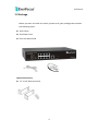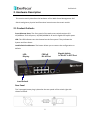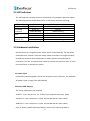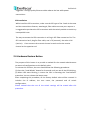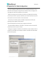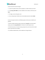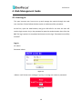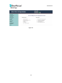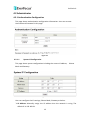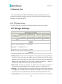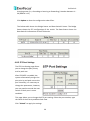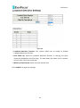
1
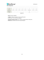
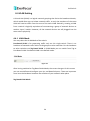
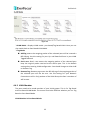
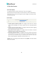
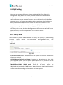
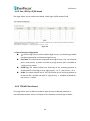
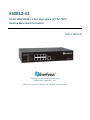
ES0812-31 8-Port 10M/100M + 2-Port Giga uplink (1*TP+1*SFP) Desktop Web Smart PoE Switch User’s Manual Copyright © EverFocus Electronics Corp, Release Date: September, 2013 Notice: This content is subject to be changed without notice. EVERFOCUS ELECTRONICS CORPORATION PoE Switch User’s Manual 2013 EverFocus Electronics Corp www.everfocus.com All rights reserved. No part of the contents of this manual may be reproduced or transmitted in any form or by any means without written permission of the Everfocus Electronics Corporation. Release Date: September, 2013 QuickTime is a registered trademark of the Apple Computer, Inc. Windows is a registered trademark of the Microsoft Corporation. Linksys is a registered trademark of the Linksys Corporation. D-Link is a registered trademark of the D-Link Corporation. DynDNS is a registered trademark of the DynDNS.org Corporation. Other product and company names mentioned herein may be the trademarks of their respective owners. Safety Precautions FCC Warning This Equipment has been tested and found to comply with the limits for a Class-A digital device, pursuant to Part 15 of the FCC rules. These limits are designed to provide reasonable protection against harmful interference in a residential installation. This equipment generates, uses, and can radiate radio frequency energy. It may cause harmful interference to radio communications if the equipment is not installed and used in accordance with the instructions. However, there is no guarantee that interference will not occur in a particular installation. If this equipment does cause harmful interference to radio or television reception, which can be determined by turning the equipment off and on, the user is encouraged to try to correct the interference by one or more of the following measures: Reorient or relocate the receiving antenna. Increase the separation between the equipment and receiver. Connect the equipment into an outlet on a circuit different from that to which the receiver is connected. Consult the dealer or an experienced radio/TV technician for help. CE Mark Warning This is a Class-A product. In a domestic environment this product may cause radio interference in which case the user may be required to take adequate measures. Table of Contents 1. Introduction ...................................................................................................... 1 1.1 Product Overview................................................................................................. 1 1.2 Key Features ......................................................................................................... 1 1.3 Package ................................................................................................................ 4 2. Hardware Description ....................................................................................... 5 2.1 Product Outlook: .............................................................................................. 5 2.2 LED Indicators................................................................................................... 6 2.3 Hardware Installation ....................................................................................... 6 2.4 Hardware Restore Button ................................................................................ 7 3 Preparation for Web Configuration ..................................................................... 8 4. Web Management Guide..................................................................................10 4.1 User Log In ..................................................................................................... 10 4.2 Administrator ................................................................................................. 12 4.2.1 Authentication Configuration ..................................................................... 12 4.2.1.1 System IP Configuration ....................................................................... 12 4.2.1.2 System Status ....................................................................................... 14 4.2.1.3 Load Default Setting ............................................................................. 15 4.2.1.4 Firmware Update ................................................................................. 16 4.3 Port Management .............................................................................................. 18 4.3.1 Port Configuration .................................................................................... 18 4.3.2 Port Mirroring .......................................................................................... 20 4.3.3 Bandwidth Control ................................................................................... 20 4.3.4 Broadcast Storm Control .......................................................................... 21 4.3.5 PoE ........................................................................................................... 22 4.4 VLAN Setting ...................................................................................................... 24 4.4.1 VLAN Mode .............................................................................................. 24 4.4.2 VLAN Member .......................................................................................... 25 4.4.3 Multi to 1 Setting ..................................................................................... 29 4.5 Per Port Counter ................................................................................................ 30 4.5.1 Port Counter ................................................................................................ 30 4.6 QoS Setting......................................................................................................... 32 4.6.1 Priority Mode .............................................................................................. 32 4.6.2 Port, 802.1p, IP/DS based ........................................................................... 33 4.6.3 TCP/UDP Port Based.................................................................................... 33 4.7 Security .............................................................................................................. 35 4.7.1 MAC Address Binding .................................................................................. 35 4.7.2 TCP/UDP Filter ............................................................................................. 36 4.8 Spanning Tree ..................................................................................................... 38 4.8.1 STP Bridge Settings...................................................................................... 38 4.8.2 STP Port Settings ......................................................................................... 39 4.8.3 Loopback Detection Settings ...................................................................... 40 4.9 Trunking.............................................................................................................. 42 4.10 Backup/Recovery ............................................................................................. 44 4.11 Miscellaneous .................................................................................................. 45 4.12 Logout .............................................................................................................. 48 4.13 Q&A .................................................................................................................. 49 PoE Switch 1. Introduction 1.1 Product Overview The switch is 8-port 10M/100M + 2 port Giga uplink (1*TP+1*SFP) Desktop Web Smart PoE Switch, the switch supports IEEE 802.3at Power over Ethernet standard, up to 30W per port, maximum 130W power consumption per system and no special network cable required for your PD devices. The switch also provides exceptionally smart Web management features, such as VLAN, QoS, RSTP, LACP, Port Security…etc. The switch is designed for small or medium network environment to strengthen its network connection. This product is compact 11” size, making it ideal for Desktop users with limited space. It also gives you the option of installing it in a 19” cabinet by rack-mount kits or underneath a desk. 1.2 Key Features Standard Standard IEEE 802.3 10BaseT IEEE 802.3u 100BaseTX IEEE 802.ab 1000BaseT IEEE 802.3z 1000BaseSX/LX IEEE 802.3x Full-duplex and Flow Control IEEE 802.3ad Link Aggregation IEEE 802.1Q VLAN IEEE 802.1D Spanning tree protocol IEEE 802.1p Class of Service IEEE 802.1w Rapid Spanning tree protocol IEEE 802.at Power over Ethernet (PoE+) 1 PoE Switch Interface Number of Port: 10 Fast Ethernet: 8-port 10/10 Base-TX with IEEE 802.3at PoE+ Gigabit Ethernet: 1-port 10/100/1000 Base-T, 1-port Gigabit SFP Performance MAC Address: Up to 4K Buffer Memory: 2.75Mb Transmission Method: Store and Forward Mechanism Software Feature Description Port Management Port Configuration: Enable/Disable such as Link State, Speed/Duplex, Flow Control, Address Learning; Monitor Link Status Port Mirroring: One to one, one to many, many to one mirroring Bandwidth Control: Up to 256 levels Bandwidth Control for TX and RX Rate Broadcast Storm Control: Broadcast Storm Control and Threshold Setting PoE Control: PoE Enable/Disable, PoE Status Port Counter (Statistic): Monitor the port statistic VLAN Setting VLAN Mode: Port-based and Tag-based VLAN Port Based VLAN: Up to 10 ports Port-Based VLAN Tag Based VLAN: Up to 32 VLANs, Available DID from 1~4094 QoS Setting Support High & Low Priority Queue Priority Mode: First-In-First-Out, Strict and Weight-Round-Robin (WRR) Priority Mode Class of Service schemes: 802.1p,IP TOS/DS or Port Base TCP/UDP Port & Priority queue mapping Security Setting Port Security - Port & MAC Address Binding, up to 3 MAC Address per port TCP/UDP Filtering: Protocol Port Filter for secure WAN Port 2 PoE Switch Spanning Tree Protocol Version: Support Legacy Spanning Tree Protocol & Rapid Spanning Tree Protocol Loopback Detection: Loopback detection to avoid network loop. Trunking Trunking Type: Static Trunk or LACP Trunk Group: 1, Gigabit Port 9 and Port 10 can be aggregated LACP Long/Short Timeout time IGMP Snooping V1&V2 Basic Features Embedded HTTP web Management User name/Password Authentication Configuration Configuration Backup/Recovery TFTP Firmware upgradeable Secure Management LED LED Indicator System: Power Per Port: Link/ Act PoE Port: Act/Status Power Power Input: 100~240V/AC, 50~60HZ PoE Power Output: 802.3at compliant, 30W Max. per Port Power Consumption: 130Watts (Max) Product Dimensions/ Weight Dimension : 44 × 266 × 160 mm (H x W x D) Weight : 1.8kg 3 PoE Switch 1.3 Package Before you start to install this switch, please verify your package that contains the following items: One Switch One Power Cord One User Manual CD Optional Accessory: 11” to 19” Rack-mount kit 4 PoE Switch 2. Hardware Description This section mainly describes the hardware of the Web-Smart Management PoE Switch and gives a physical and functional overview on the certain switch. 2.1 Product Outlook: Front Ethernet Ports: The front panel of the web smart switch consists of 8 10/100Base-TX RJ-45 ports,1 10/100/1000M RJ-45 and 1 Gigabit SFP uplink ports. LED: The LED Indicators are also located on the front panel. They indicate the System and Port Status. Load Default Push Button: The button allows you to restore the configuration to default. LED Display FE/PoE RJ-45 Port Gigabit Uplink 1x RJ-45/ 1x SFP Port Load Default Rear Panel The 3-pronged power plug is placed at the rear panel of the switch right side shown as below. 5 PoE Switch 2.2 LED Indicators The LED Indicators present real-time information of systematic operation status. The following table provides description of LED status and their meaning. LED Power 10/100M Link/ ACT PoE 1000M (Port 9-10) Color/Status Amber On Green On Green Blinking Amber On Off Green On Green Blinking Description Power on Link Up Data activating Port is linked to Power Device No Power Device is connected Link Up Data activating 2.3 Hardware Installation Set the switch on a large flat space with a power socket close by. The flat space should be clean, smooth, level and sturdy. Make sure there is enough clearance around the switch to allow attachment of cables, power cord and allow air circulation. The last, use twisted pair cable to connect this switch to your PC then user could start to operate the switch. AC Power Input Connect the attached power cord to the AC power input connector, the available AC power input is range from 100-264VAC. Ethernet cable Request The wiring cable types are as below. 10 Base-T: 2-pair UTP/STP Cat. 3, 4, 5 cable, EIA/TIA-568 100-ohm (Max. 100m) 100 Base-TX: 2-pair UTP/STP Cat. 5 cable, EIA/TIA-568 100-ohm (Max. 100m) 1000 Base-T: 4-pair UTP/STP Cat. 5 cable, EIA/TIA-568 100-ohm (Max. 100m) PoE: To delivery power without problem, the Cat 5/5e and Cat 6 cable is 6 PoE Switch suggested. The high quality Ethernet cable reduces the lost while power transmission. SFP Installation While install the SFP transceiver, make sure the SFP type of the 2 ends is the same and the transmission distance, wavelength, fiber cable can meet your request. It is suggested to purchase the SFP transceiver with the switch provider to avoid any incompatible issue. The way to connect the SFP transceiver is to Plug in SFP fiber transceiver fist. The SFP transceiver has 2 plug for fiber cable, one is TX (transmit), the other is RX (receive). Cross-connect the transmit channel at each end to the receive channel at the opposite end. 2.4 Hardware Restore Button The purpose of this button is to provide a method for the network administrator to restore all configurations to the default value. To activate this function, the user should follow the following procedures. (1) Press the “Load default” button for 3 seconds until you see all the LED blinking. (2) When LED starts blinking, it means the CPU is executing the “load default” procedure. You can release the button now. After completing this procedure, all the factory default value will be restored. It includes the IP address, the user name, the password and all switch configurations. Please noticed that the rest of the switch settings will be erased after this procedure. 7 PoE Switch 3 Preparation for Web Configuration The web management page allows you to use a standard web-browser such as Microsoft Internet Explorer, Google Chrome or Mozila Firefox, to configure and interrogate the switch from anywhere on the network. Before you attempt to use the web user interface to manage switch operation, verify that your Switch is properly installed on your network and that every PC on this network can access the switch via the web browser. Verify that your network interface card (NIC) is operational, and that your operating system supports TCP/IP protocol. Wire the switch power and connect your computer to the switch. The switch default IP address is 192.168.2.1. The Switch and the connected PC should locate within the same IP Subnet. Change your computer’s IP address to 192.168.2.XX or other IP address which is located in the 192.168.2.x (For example: IP Address: 192.168.2.30; Subnet Mask: 255.255.255.0) subnet. 8 PoE Switch Launch the web browser and Login. 1. Launch the web browser (Internet Explorer or Mozila Firefox) on the PC. 2. Type http://192.168.2.1 (or the IP address of the switch). And then press Enter. 3. The login screen will appear next. 4. Key in the password. Default user name and password are both admin. If you can’t login the switch, the following steps can help you to identify the problem. 1. Switch to DOS command mode and type the “ipconfig” to check the NIC’s setting. Type the “ping 192.168.2.1” to verify a normal response time. 2. Check the security or Firewall settings, high security level may limit the web access. Check with the IT people. 3. Try different Web-browser, like the Mozila or Google Chrome. 9 PoE Switch 4. Web Management Guide 4.1 User Log In This part instructs user how to set up and manage the switch through the web user interface. Please follow the description to understand the procedure. At the first, open the web browser, and go to 192.168.2.1 site then the user will see the login screen. Key in the password to pass the authentication then clicks the OK. The log in process is completed and comes out the sign “Password successfully entered”. Log in ID: admin Password: admin Figure 1-1 ※Note: It will show error message if you key in wrong user name or password. Figure 1-2 10 PoE Switch Main Page Figure 1-3 11 PoE Switch 4.2 Administrator 4.2.1 Authentication Configuration This page shows authentication configuration information. User can set new Username and Password in this page. Figure 2-1 4.2.1.1 System IP Configuration This page shows system configuration including the current IP address, Mask and Gateway. Subnet Figure 2-2 User can configure the IP settings, Subnet Mask, Gateway as below: IP Address: Manually assign the IP address that the network is using. The default IP is 192.168.2.1 12 PoE Switch Subnet Mask: Assign the subnet mask to the IP address. Gateway: Assign the network gateway for industrial switch. IP Configure: Select the Static or DHCP. The default setting is Static, you can manually configure the IP Address settings. Select DHCP mode means the switch acts as the DHCP client and the switch will try get the IP Address from the DHCP server. Click Update to update the new settings. It will show “update successfully” then press Reboot button. It will enter user login screen automatically Click DHCP -> Update, you can see the warning message. Note: After changed to DHCP mode, the switch must be restarted to get new IP address, however, since the switch only provide web management, it is hard for user to find its new IP. Please don’t try this mode without pre-configured DHCP setting in DHCP Server. 13 PoE Switch 4.2.1.2 System Status This page displays the information about the switch of MAC address, how many Physical Ports it has, System Version and Idle Time Security. Besides, users can also fill in up to 15 characters in the Comment, Contact and Location field for note. Figure 2-3 MAC Address: Displays the unique hardware address assigned by manufacturer (default). Number of Ports: Displays number of ports in the switch. Comment: Add character here for not. System Version: Displays the switch’s firmware version. Idle Time Security: User can set the time security. When user leave the computer for a moment, the software will auto logout or back to the last display. Click Update button to update the information. The system may request you to restart the switch, please follow the instruction. Figure 2-4 Time Out after the Idle Time Time Out 14 PoE Switch 4.2.1.3 Load Default Setting Clicking the Load button will make the switch being set to the original configuration. Figure 2-4 ※ Note: It exclude to change user name, password and IP configuration. If you want to restore default setting including IP and user name password, then you can press the reset button for hardware base reset. More detail information about Load Default Setting – Hardware Base is activated by click Load Default Button. The procedure is described as following. The purpose of this button is to provide a method for the network administrator to restore all configurations to the default value. To activate this function, the user should follow the following procedures. (1) Press the “Load default” button for 3 seconds until you see all the LED blinking. (2) When LED starts blinking, it means the CPU is executing the “load default” procedure. You can release the button now. After completing this procedure, all the factory default value will be restored. It includes the IP address, the user name, the password and all switch configurations. Please noticed that the rest of the switch settings will be erased after this procedure. 15 PoE Switch 4.2.1.4 Firmware Update Before the firmware update procedure is executed, you should enter the password twice and then press Update button. Figure 2-5 The popup warning window appears for making sure you want to proceed the firmware upgrading process. Notice that the code of flash memory will be erased. All functions will be detected except the firmware update itself. If want proceed, click “Yes” to continue. If not, please click “Cancel”. Figure 2-6 The smart switch will erase the flash memory. There is a self-protection mechanism in the Boot Loader, so the Boot Loader will keep intact. Even though the power is turned off or the cable link fails during the firmware update procedure, the Boot loader will restore the code to firmware update page. 16 PoE Switch After pressing Update button, the old web code will be erased. Then you can click “Browse” to select the image file. Figure 2-7 After selected the image file. The place right of the Browse command will display the file name you selected. Press “Update” to continue the firmware upgrading process. Figure 2-8 The below screen shows the Uploading process is starting. Figure 2-9 After firmware correctly uploaded, the web screen shows OK. Type “Continue” to re-login the switch. Figure 2-10 ※Note: The reboot is for software base instead of hardware base. 17 PoE Switch 4.3 Port Management Port Management includes Port Configuration, Port Mirroring, Bandwidth Control, Broadcast Storm Control and PoE 4.3.1 Port Configuration In Port Configuration, you can set and view the operation mode for each port. Figure 3-1 Port Configuration Function: Tx/Rx-Ability: Enable or Disable. The default value is “Enable”. Being set as “Enable”, the port can Transmit and Receive packet without any problem. After changed to “Disable”, the selected ports can access the network any more. Auto-Negotiation: Enable and Disable. Being set as ‘Enable’, the Speed, Duplex mode, Pause, Backpressure, TX Capability and Address Learning are negotiated automatically. When you set it as ‘Disable’, you have to assign those items manually. 18 PoE Switch Speed: When the Auto-Negotiation column is set as Disable, users have to set the connection speed to the ports ticked. Duplex: When the Auto-Negotiation column is set as Disable, users have to set the connection mode in Half/Full to the ports ticked. Pause: Flow Control for connection at speed of 10/100Mbps in Full-duplex mode. Backpressure: Flow Control for connection at speed of 10/100Mbps in Half-duplex mode. Addr. Learning: When the Auto-Negotiation column is set as Disable, users have to set this column as Enable or Disable. Select Port No.: Select the port/ports you want to apply to. You can select one or multiple ports here. Click Update to have the configuration take effect. Current Status: Displays the status of each ports. This field indicates the port 6 is link up and run as 100M Full, Flow Control Enabled. Setting Status: Displays the configuration of each ports. 19 PoE Switch 4.3.2 Port Mirroring The Port mirroring is a method for monitoring traffic in switched networks. That Traffic through ports can be monitored by any of the ports means traffic goes in or out monitored (source) ports will be duplicated into mirroring (destination) port. Figure 3-2 Destination (mirroring) port for monitoring Rx only, Tx only or both RX and TX traffic which come from the source port. Users can connect the mirroring port to LAN analyzer or Netxray. Monitored Packets: Pull down the selection menu to choose what type of packet is to be monitored. Rx indicates the Received Packets, Tx indicates the Transmitted Packets. Tx & Rx indicates Both Transmit and Received. Source Port: The ports that the user wants to monitor. All monitored port traffic will be copied to mirroring (destination) port. Users can select multiple source ports by ticking the check boxes beneath the port number label to be monitored. And then, click Update to have the configuration take effect. 4.3.3 Bandwidth Control This page allows the setting of the bandwidth for each port. The TX rate and Rx rate can be filled with the number ranging from 1 to 255. This number should be multiplied by the selected bandwidth resolution to get the actual bandwidth. 20 PoE Switch Figure 3-3 Port No.: Select the port number you want to configure. Tx Rate: Type the Tx Rate value. The value is range from 0-255. Rx Rate: Type the Rx Rate value. The value is range from 0-255. Speed Base: Low: step by 32Kbps. High: step by 256Kbps for Fast Ethernet Ports. 2048Kbps for Gigabit Ports. Click Update to have the configuration take effect. Example: Type 5 for both Tx and Rx Rate and select the High as speed base for port 1 and port 10. The actual rate for port 1 (Fast Ethernet) is “1280”, for port 9 (Gigabit Port) is 10240. You could see the table is updated as below. Figure 3-4 4.3.4 Broadcast Storm Control The switch implements a broadcast storm control mechanism. Tick the check boxes to have them beginning to drop incoming broadcast packets if the received broadcast packet counts reach the threshold defined. Each port’s broadcast storm protection function can be enabled individually by ticking the check boxes. 21 PoE Switch Figure 3-5 The broadcast packet is only checked at the selected port and the number of broadcast packets is counted in every time unit. The one time unit indicates the number of broadcast packet which is allowed to enter each port in one time unit. The one time unit is 50us for Gigabit speed, 500 us for 100Mbps speed and 5000us for 10Mbps speed. The excessive broadcast packet will be discarded. For those broadcast packets incoming from the un-selected port, the switch treats it as the normal traffic. Threshold: Type in the threshold in the range between 1 and 63 to limit the maximum byte counts, which a port can send or receive in a period of time. Enable Port: Having ticked the boxes, the port will stop transmitting or receiving data when their sending byte counts or receiving byte counts reach the defined threshold. Example to change one time unit to pps: The port 1 is 100M port. The one time of it is 500us, it indicates there are 2,000packets can be sent within one second. While type 10 to port 1, that means 10x2000 packets can be sent in one second. Click Update to have the configuration take effect. 4.3.5 PoE User could know per PoE port out power status in this page and also enable or disable per port. 22 PoE Switch Figure 3-6 Port: The port number. Enable: Enable PoE feature of the specific ports. PSE Current: The PSE Current Range. Minimum Output Power: The minimum output power of the port. PoE Class: The PoE class of the connected port. 23 PoE Switch 4.4 VLAN Setting A Virtual LAN (VLAN) is a logical network grouping that limits the broadcast domain, which would allow you to isolate network traffic, so only the members of the same VLAN will receive traffic from the ones of the same VLAN. Basically, creating a VLAN from a switch is logically equivalent of reconnecting a group of network devices to another Layer 2 switch. However, all the network devices are still plugged into the same switch physically. 4.4.1 VLAN Mode You may select the VLAN Mode of the switch. Port-based VLAN is for separating traffic only on this single switch. There is no handover of network traffic within VLAN groups to other switches. For the handover to other switches use Tag Based VLAN. In VLAN Mode you can switch from Tag to Port Based VLAN. Port Based VLAN is the default mode. Figure 4-1 After having switched to Tag Based VLAN Mode, the screen changes. On this screen you can now define and configure your Up- and Downlink ports. These are important since here the handover between the switches of your network takes place. Tag Based VLAN Mode 24 PoE Switch Figure 4-2 VLAN Mode : Displays VLAN mode : port based/Tag based VLAN. Here you can also switch back to Port Based VLAN Mode Tag Mode: AddTag means the outgoing packet of the selected port will be inserted a 802.1Q tag. Use this setting for your Up- and Downlink Ports in your VLAN Tagged Network. don’t care: Don’t care means the outgoing packet of the selected port keep the original packet received at the source port. This is the default setting when starting VLAN configuration. You should change to either Add or Remove Tag. Remove Tag: Remove tag means the 802.1Q tag of the outgoing packet of the selected port will not be sent. Use this setting for your Network Connections to PCs. Only packets of the VLAN Group the Port is member of will be sent. 4.4.2 VLAN Member The ports need to be made member of your VLAN groups. This is for Tag Based and Port Based VLAN Mode. The screen here looks different whether you run Tag Based or Port Based Mode. VLAN Member in Port Based Mode 25 PoE Switch Figure 4-3 In Port Based Mode you see a matrix of your 10 Ports. Simply select the port on top screen you want to configure, click on Read, and then select or deselect the ports that are on the same VLAN group. In this configuration mode you do not need to worry about defining VLAN groups and VLAN IDs. VLAN Member in Tag Based Mode In Tag Based Mode you need to define and configure your VLAN groups. Assign the VLAN ID, select the VLAN member ports, assign the PVID and check the configuration result. 26 PoE Switch VLAN ID (VID): Since you want the handover to other switches take place smoothly, the VLAN IDs (Numbers) need to be like on the rest of your network. (On other switches you may have the chance to configure names. These are just for your reference. Only the numbers are important!) Add: Enter a VID, select the VLAN member for this entry and then press this button to add a VLAN entry to the table. The available range of VID is from 1-4094. Delete: Select a VID in the table and then press this button to remove a VID entry from the table. After deleted, the VLAN and its member port setting is gone. Update: Modify the existing VLAN setting. Select the VID, the below settings will be displayed, you can change the settings and then press the Update button to update the setting.s. VLAN Member Port Select : Select the VLAN Member here. 27 PoE Switch VID Source Port : This table allows you to configure PVID of the port. Select the port number while you add VLAN and select VLAN member ports, the selected ports’ PVID will be the VID you typed. Please noted that one port only can have one PVID. While one port joins multiple VLAN groups, the PVID is important to identify where the incoming traffic will be forwarded to. For example: Port 3 is the member of VLAN 100 and 200, PVID of it is 100. The traffic received from the connected PC is usually untagged, the incoming packets will then be tagged with PVID within the switch and then follow the VID table to forward traffic. Port VID Map : This table shows the PVID of the ports. VLAN Member Table : This table shows the VID and its member ports. Configuration Steps: First, add your VLAN Groups (identified throughout your network by unique and constant numbers). Start with IDs from 100 and up is often. Starting with 100 gives you enough free room and less compatibility issues. Second, enter “100” in the field right of VID Setting, then select or deselect which ports are member of that group. Your up- and downlink ports need to be the member of every existing group. If the port joins different VLAN groups, the VID 28 PoE Switch Source Port allows you to define the PVID. After configured and selected. Then click on Add to create the table and related port mapping. The new group with its setting will be displayed at the bottom of the screen. 4.4.3 Multi to 1 Setting Multi to 1 VLAN is used in CPE side of Ethernet-to-the-Home and is exclusive to VLAN setting on VLAN Member Setting. When VLAN member Setting is updated, multi to 1 setting will be void and vice versa. The disable port means the port which will be excluded in this setting. All ports excluded in this setting are treated as the same VLAN group. In a normal Tag Based VLAN network you will not need this configuration option. Figure 4-5 29 PoE Switch 4.5 Per Port Counter 4.5.1 Port Counter This page provides port counter of each port. There are 4 categories: Receive Packet & Transmit Packet/ Transmit & Collision / Receive Packet & Drop /Receive & CRC error. Once you change the counter category, the counter will be cleared automatically. Figure 5-1 Transmit packet & Receive packet: This category shows both the received packet count (excluding the incorrect packet) and the transmitted packet count. Collision Count & Transmit packet: This category shows the packets outgoing from the switch and the count of collision. Drop packet & Receive packet: This category shows the number of received valid packet and the number of dropped packet. CRC packet & Receive packet: This category shows the received correct packet and received CRC error. Once your see CRC error increasing here, please notice that there may be hardware issue, the possible reason could be switch port failure, cable lose/broken, cable/fiber connector failure...etc. Update: Select the existing Counter Mode and click Update, the below statistic table will be updated. 30 PoE Switch Clear: Press “clear” will clear all counters. Refresh: Press “Refresh” button will aggregate the number of the counter for all ports. 31 PoE Switch 4.6 QoS Setting Here you can configure QoS policy priority mode and CoS (Class of Service) configuration. QoS (Quality of Service) refers to mechanisms in the network software that make the actual determination of which packets have priority. CoS refers to feature sets, or groups of services, that are assigned to users based on company policy. If a feature set includes priority transmission, then CoS winds up being implemented in QoS functions within the routers and switches in the network. In an enterprise network, class of service (CoS) differentiates high-priority traffic from lower-priority traffic. Tags may be added to the packets to identify such classes, but they do not guarantee delivery as do quality of service (QoS) functions, which are implemented in the network devices. 4.6.1 Priority Mode There are three priority modes available to specify the priority of packets being serviced. Those include First-In-First-Out, All-High-Before-Low, and Weight-Round-Robin. Figure 6-1 First-In-First-Out: Packets are placed into the queue and serviced in the order they were received. All-high-before-low(Strict priority):All packets will be assigned to either high priority queue (Queue 2) or low priority queue (Queue 1). The packet on the low priority queue will not be forwarded until the high priority queue is empty. Weight-Round-Robin (WRR) mode: There are 4 priority queues for Weighted-and-round-robin (WRR) mode. When this mode is selected, the traffic will be forwarded according to the number set in each queue. 32 PoE Switch 4.6.2 Port, 802.1p, IP/DS based The page allows you to enable Port Based, VLAN Tag or IP/DS mode of COS. Figure 6-2 Class of Service Configuration =Enable High Priority. After Enabled High Priority, the following enabled Port Based parameter will become High Priority. Port Base: The selected port equipped with High Priority. The non-selected port is Low priority. A packet received by a high priority port is handled as a high priority packet. VLAN Tag: The switch follows the VLAN tag of the incoming packets to forward traffic. VLAN Tag priority: high priority -> 4~7 ; low priority -> 0~3 IP/DS: The switch follows the IP TOS / Diff Serve of the incoming packets to forward traffic. Ipv4 DS and Ipv6 TC: high priority -> 10,18,26,34,46,48,56 ; low priority -> others 4.6.3 TCP/UDP Port Based This page allows user to define the Option type of the pre-defined protocols or user-defined protocols. Select the Option of the Protocol as below figure shown. 33 PoE Switch Figure 6-3 The pre-defined Protocols Figure 6-4 The User-defined Protocols The Class of Service for TCP/UDP port number allows the network administrator to assign the specific application to a priority queue. F-I-F-O: The incoming packet will be forwarded in first-in-first-out scheme. Discard: The incoming packet will be discarded at the source port. High: The incoming packet will be forwarded with the high priority. Low: The incoming packet will be forwarded with the Low priority. 34 PoE Switch 4.7 Security The Security feature allows you to enable Port Security (MAC Address Binding) and TCP_UDP Filter feature. 4.7.1 MAC Address Binding This is also known as Port Security funciton of some other switch. The feature allows you to bind 1-3 MAC address to one physical port. After the port and MAC address is binded, only the allowed MAC Address can access the switch. The upper table allows you to bind the MAC address to one specific port. Figure 7-1 MAC Address: Type the target MAC address you want to bind for the specific port. User can assign up to 3 MAC addresses to the port. Select Port: Select the port number and click “Read” button. If you don’t enter any MAC Address before, the address is blank. If you have entered any MAC address, the field will display the MAC addresses your previously entered. Binding: Enable or Disable. Select Enable to enable the MAC Address Binding feature. Update: After selected the port, enabled Binding and entered MAC Address, click “Update” to update and save the settings. The lower table shows the binding status of the port. 35 PoE Switch Figure 7-2 This table shows the binding status of the port 1 is enabled. 4.7.2 TCP/UDP Filter This page allows user to configure the TCP/DUP limit. Figure 7-3 Function Enable: To Enable or Disable the function. Port Filtering Rule: The outgoing packet with selected protocol will be either forwarded or dropped at secure WAN port as the figure shown below. “negative” means the selected protocol will be dropped and other protocols will be forwarded. “positive” means the selected protocol will be forwarded and other protocol will be dropped. Protocol: Select the pre-defined known protocol or User_Define Protocol number. Secure WAN Port: The port number of the Secured WAN Port. The secured WAN port is the Egress Port. The configured limit packet will be dropped. 36 PoE Switch Click Update to have the configuration take effect. 37 PoE Switch 4.8 Spanning Tree The switch supports IEEE 802.1D-2004 RSTP protocol, the RSTP protocol can backward compatible to legacy Spanning Tree Protocol (STP) and 802.1w Rapid Spanning Tree Protocol (RSTP). 4.8.1 STP Bridge Settings The Table allows you to configure STP Mode and the system time settings. Figure 8-1 STP Mode: Disable, STP and RSTP. Select the STP version you want to enabled. Bridge Priority: This parameter configures the spanning tree priority globally for this switch. The device with the highest priority becomes the STP root device. However, if all devices have the same priority, the device with the lowest MAC address will then become the root device. Number between 0 – 61440 in increments of 4096. Therefore, there are 16 distinct values. Hello Time: Interval (in seconds) at which the root device transmits a configuration message (BPDU frame). Number between 1-10 (default is 2). Max Age – The maximum time (in seconds) a device can wait without receiving a configuration message before attempting to reconfigure. That also means the maximum life time for a BPDU frame. Number between 6-40 (default is 20). Forward Delay: The maximum time (in seconds) the root device will wait before 38 PoE Switch changing states (i.e., discarding to learning to forwarding). Number between 4 – 30 (default is 15) Click Update to have the configuration take effect. The below table shows the Bridge Status and Root Switch’s Status. The Bridge Status shows the STP configuration of the switch. The Root Status shows the Root Switch’s Information of the STP domain. 4.8.2 STP Port Settings The STP Port Setting page allows you to change the port priority and its path cost. After STP/RSTP is enabled, the system automatically assigns the port priority and path cost to the prot. Normally, it is necessary to change the parameters, however, you may need to control the root switch or block port in some condition. This page allows you to change the STP port setting. Select the port number, type the value of the Priority and Root Path Cost. Click “Submit” to apply the settings. 39 PoE Switch Figure 8-2 Port No: The port ID. It cannot be changed. Aggregations mean any configured trunk group. Root Path Cost: This parameter is used by the STP to determine the best path between devices. Therefore, lower values should be assigned to ports attached to faster media, and higher values assigned to ports with slower media. Set the RSTP path cost on the port. Number between 0 – 200000000. 0 means auto generated path cost. State: Show the current port state includes Designated port, Root port or Blocked port. Status: Show the current port status includes Forwarding, Disable, Blocking...etc. 4.8.3 Loopback Detection Settings In some condition, the user may incorrectly connect the wrong port and lead the network loop. The unknown broadcast, multicast may crash the whole network. The Loopback Detection feature can help you leave the risk. 40 PoE Switch Figure 8-3 Loopback Detection Function: This column allows you to enable or disable Loopback Detection function. Auto Wake Up: Once the Loopback Detection function is running, the ports maybe be disabled to avoid the loop. The Auto Wake Up allows you to activate the port after Time Interval passed. Wake-Up Time Interval: Select the time interval here. Click “Submit” to apply the settings. 41 PoE Switch 4.9 Trunking Port trunk allows multiple links to be bundled together and act as a single physical link for increased throughput. It provides load balancing, and redundancy of links in a switched inter-network. Actually, the link does not have an inherent total bandwidth equal to the sum of its component physical links. Traffic in a trunk is distributed across an individual link within the trunk in a deterministic method that called a hash algorithm. The hash algorithm automatically applies load balancing to the ports in the trunk. A port failure within the trunk group causes the network traffic to be directed to the remaining ports. Load balancing is maintained whenever a link in a trunk is lost or returned to service. This switch may use Source MAC Address or a combination of Source MAC Address and Destination MAC Address to be the selection for Trunk Hash Algorithm. Traffic pattern on the network should be considered carefully before applying it. When a proper hash algorithm is used, traffic is kind of randomly decided to be transmitted across either link within the trunk and load balancing will be seen. This switch supports one trunk group, port 9 and Port 10. Trunk hash algorithm support Source MAC, Source&Destination MAC Address. Figure 9-1 System Priority: This column allows you to enable or disable Loopback Detection function. Link Aggregation Algorithm: MAC Src: Hash Algorithm based on Source MAC Address. MAC Src&Dst: Hash Algorithm based on Source & Destination MAC Address XOR result. 42 PoE Switch Figure 9-2 Member: This column allows you to select the member Ports. Status: This column allows you to Enable/Disable the Trunk Group. Type: This column allows you to choose Static Trunking or Dynamic LACP Trunking. After Select the LACP Trunk type, the following parameters can be configured. Please noted that the parameters of the both ends of the LACP should be the same. Operation Key: This column allows you to type operation key. Time Out: This column allows you to select Long Time Out Time or Short Time Out Time. The Long Time Out is around 30 seconds, the Short Time Out is around 3 seconds, however, the link partner of other supplier may not use the same value. The longer time then will be used. Activity: This column allows you to select Passive or Active mode. Note: If you enable LACP on some specified ports and their link partners are normal port without LACP, these specified ports cannot transmit packet to/receive packet from the link partner. 43 PoE Switch 4.10 Backup/Recovery This function provides the user with a method to Backup/Recovery the switch configuration. The user can save configuration file to a specified file. If the user wants to recover the original configuration, which is saved at the specified path, just enter the password and then press the “upload” button. Finally the original configuration of the switch will be recovered. Figure 10-1 44 PoE Switch 4.11 Miscellaneous Miscellaneous setting is used to configure output queue aging time, VLAN stride and IGMP snooping. Figure 11-1 Output Queue Aging Time: Purpose: This function is used to avoid the traffic jam on one port will not cause the congestion of other ports. In some application, for example the IPTV Multicast communication, the multicast stream is continuously generating from the source port, the client port may be congested because of the limited bandwidth or slow network processing ability. Then, the Pause frame of Flow Control will be generated once the packet buffer is full. With the Output Queue Aging Time feature, when a packet is stored at output queue in a switch for a long time will be aged out and become a useless packet. 45 PoE Switch Aging Time: This command allows user to disable the feature or configure the aging timeout time to 200ms, 400ms, 600ms or 800ms. VLAN Striding: Purpose: For some network environment, the network administrator probably want to filter undesired broadcast or multicast packet to enhance the network bandwidth utilization and forward meaningful unicast to a specific destination. VLAN is a good mechanism to block broadcast packet, but it can also block the unicast packet communication between VLANs. To solve this issue, a special function called “VLAN striding” is designed to achieve this purpose. If VLAN striding is enabled, the packet will be forwarded to the destination port directly, the unicast packet can stride across VLAN. VLAN Striding: By selecting this function, the switch will forward uni-cast packets to the destination port, no matter whether destination port is in the same VLAN. IGMP Snooping V1 & V2: Purpose: A switch will, by default, flood multicast traffic to all ports in a broadcast domain. Multicast can cause unnecessary load on host devices by requiring them to process packets they have not solicited. The IGMP snooping is a feature that allows the switch to listen in on the IGMP conversation between hosts and routers. By listening (also known as snooping) to these conversations, the switch maintains a map of which ports (clients) need which multicast stream (source). Multicast may be filtered which do not need them, Multicast may be forwarded only to the IGMP group it joined. IGMP Snooping: When this function is enabled, the switch will execute IGMP snooping version 1 and version 2 without the intervention of CPU. The IGMP report and leave packets are automatically handled by the switch. The next setting, IGMP Leave Packet can be enabled or disabled. After enabled, the Leave packet will be forwarded to IGMP router ports. VLAN Uplink: Purpose: This switch does not implement Independent VLAN (IVL) MAC address table, it utilizes VLAN uplink to emulate the function of IVL. An independent VLAN MAC address table is based on both the source MAC 46 PoE Switch address and the VLAN. In some application, if the Ethernet switch cannot build the separate MAC address table for different VLANs, there will be a conflict of MAC address table. To solve this problem, the switch controller utilizes the VLAN Uplink port to emulate the usage of Independent VLAN MAC Address Table. VLAN Uplink Setting: If VLAN uplink function is enabled and the destination port of an unicast packet is located at the next VLAN, this packet will be forwarded to the uplink port. Choose the Uplink Port X for the port ID. The Uplink X will be the uplink port of its VLAN. Note: There is a functional conflict between VLAN striding and VLAN uplink. Imagine what will happen if both VLAN striding and VLAN uplink are enabled simultaneously? In this case, the switch selects VLAN striding and ignores the VLAN uplink setting. 47 PoE Switch 4.12 Logout After finished configuring the switch, you can click Logout to leave the configuration page. The administrator has write access for all parameters governing the onboard agent. User should therefore assign a new administrator password as soon as possible, and store it in a safe place. 48 PoE Switch 4.13 Q&A 1. When you forgot your IP or password, please use the reset button for the factory default setting? Please take the following steps to reset the Web Smart Switch back to the original default: Step 1: Turn on the Web Smart Switch Step 2: Press and hold the reset button continuously for 5 seconds and release the reset button. Step 3: The switch will reboot for 20 seconds and the configuration of switch will back to the default setting. Figure 12-1 Key in the user ID and the password to pass the authentication; the user ID and the password are “admin” IP: 192.168.2.1 ID: admin Password: admin 49 PoE Switch Appendix 1: Revision History: Version V1.0 V1.1 V1.2 Revision History First Release Update latest product specification. Update latest figure of web UI. Add information of the Miscellaneous setting. updated: Optional Accessory: 11” to 19” Rack mount Kit. PoE Output voltage from 48V to 802.3at compliant. 50 Date Nov. 15, 2012 Jan. 9, 2013 Feb. 8, 2013 EverFocus Electronics Corp. EverFocus Taiwan: 12F, No.79, Sec. 1, Shin-Tai Wu Road, Hsi-Chih, Taipei, Taiwan TEL: +886 2 2698 2334 FAX: +886 2 2698 2380 www.everfocus.com.tw [email protected] EverFocus China - Beijing: Room 609, Technology Trade Building, Shangdi Information Industry Base, Haidian District, Beijing 100085, China TEL: +86 10 6297 3336~39 FAX: +86 10 6297 1423 www.everfocus.com.cn [email protected] EverFocus USA - California: 1801 Highland Avenue, Unit A, Duarte, CA 91010, USA TEL: +1 626 844 8888 FAX: +1 626 844 8838 www.everfocus.com [email protected] EverFocus Japan: 5F, Kinshicho City Building, 2-13-4 Koto-Bashi,Sumida-Ku, Tokyo, 130-0022, Japan TEL: +81 3 5625 8188 FAX: +81 3 5625 8189 www.everfocus.co.jp [email protected] EverFocus India: Suite 803, Housefin Bhavan, C-21, Bandra Kurla Complex, Bandra (East), Mumbai 400051, India TEL: +91 22 6128 8700 FAX: +91 22 6128 8705 www.everfocus.in [email protected] Your EverFocus product is designed and manufactured with high quality materials and components which can be recycled and reused. This symbol means that electrical and electronic equipment, at their end-of-life, should be disposed of separately from your household waste. Please, dispose of this equipment at your local community waste collection/recycling centre. In the European Union there are separate collection systems for used electrical and electronic product. Please, help us to conserve the environment we live in! EverFocus Europe - Germany: Albert-Einstein-Strasse 1, D-46446 Emmerich, Germany TEL: +49 2822 93940 FAX: +49 2822 939495 www.everfocus.de [email protected] EverFocus China - Shenzhen: 4F, No. 2, D4 Building, Wan Yelong Industrial Park, Tangtou Road, Shiyan, Baoan, Shenzhen, Guangdong 518101, China TEL: +86 755 2765 1313 FAX: +86 755 2765 0337 www.everfocus.com.cn [email protected] EverFocus USA - New York: 415 Oser Avenue, Unit S, Hauppauge, NY 11788, USA TEL: +1 631 436 5070 FAX: +1 631 436 5027 www.everfocus.com [email protected] EverFocus Europe - UK: Unit 12, Spitfire Business Park, Hawker Road, Croydon Surrey, CR0 4WD, UK TEL: +44 20 8649 9757 / +44 845 430 9999 FAX: +44 20 8649 9907 www.everfocusuk.co.uk [email protected] Ihr EverFocus Produkt wurde entwickelt und hergestellt mit qualitativ hochwertigen Materialien und Komponenten, die recycelt und wieder verwendet werden können. Dieses Symbol bedeutet, dass elektrische und elektronische Geräte am Ende ihrer Nutzungsdauer vom Hausmüll getrennt entsorgt werden sollen. Bitte entsorgen Sie dieses Gerät bei Ihrer örtlichen kommunalen Sammelstelle oder im Recycling Centre. Helfen Sie uns bitte, die Umwelt zu erhalten, in der wir leben! 51