1
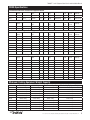
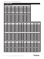
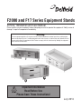
F2000 and F17 Series Equipment Stands Service, Installation and Care Manual Please read this manual completely before attempting to install or operate this equipment! Notify carrier of damage! Inspect all components immediately. Warning To assure proper operation a 2" airspace must be maintained between the lowest part of any cooking equipment and the top of this unit. Cooking equipment must have a barrier (i.e. bottom, drip pan) between its heat source and the top of the equipment stand. Failure to comply with this could severely damage the equipment stand and void all warranties. Important Information Read Before Use Please Save These Instructions! July 2013 F2000/F17 Series Equipment Stand Service and Installation Manual Important Warning And Safety Information WARNING WARNING WARNING Failure To Follow Instructions In This Manual Can Cause Property Damage, Injury Or Death. WARNING Do Not Store Or Use Gasoline Or Other Flammable Vapors Or Liquids In The Vicinity Of This Or Any Other Appliance. WARNING Unless All Cover And Access Panels Are In Place And Properly Secured, Do Not Operate This Equipment. WARNING This Appliance Is Not Intended For Use By Persons Who Lack Experience Or Knowledge, Unless They Have Been Given Supervision Or Instruction Concerning Use Of The Appliance By A Person Responsible For Their Safety. WARNING This Appliance Is Not To Be Played With. WARNING Do Not Clean With Water Jet. WARNING Do Not Use Electrical Appliances Inside The Food Storage Compartment Of This Appliance. WARNING Observe the following: WARNING WARNING WARNING WARNING WARNING Warning WARNING CAUTION 2 Read This Manual Thoroughly Before Operating, Installing, Or Performing Maintenance On The Equipment. • Minimum clearances must be maintained from all walls and combustible materials. • Keep the equipment area free and clear of combustible material. • Allow adequate clearance for air openings. • Operate equipment only on the type of electricity indicated on the specification plate. • Unplug the unit before making any repairs. • Retain this manual for future reference. For customer service, call (800) 733-8829, (800) 733-8821, Fax (989) 773-3210, www.delfield.com F2000/F17 Series Equipment Stand Service and Installation Manual Contents Receiving And Inspecting......................................................3 Serial Number Location.........................................................4 Warranty Information.............................................................4 Regulatory Certifications........................................................4 F2000 Specifications..............................................................5 Maximum Cooking Equipment Weight Capacity....................5 F17 Specifications..................................................................6 Installation......................................................................... 7-8 Operation...............................................................................9 Temperature Control Settings................................................9 Maintenance................................................................... 10-11 Refrigerator Wiring Diagrams..............................................12 Freezer Wiring Diagrams.....................................................13 Replacement Parts by Model......................................... 14-17 Condensing Unit Assemblies......................................... 18-19 Evaporator Coil Assemblies.................................................20 Drawer Assemblies..............................................................21 Replacement Part Prints......................................................22 Standard Labor Guidelines...................................................23 Receiving and Inspecting the Equipment Even though most equipment is shipped crated, care should be taken during unloading so the equipment is not damaged while being moved into the building. 1. Visually inspect the exterior of the package and skid or container. Any damage should be noted and reported to the delivering carrier immediately. 2. If damaged, open and inspect the contents with the carrier. 3. In the event that the exterior is not damaged, yet upon opening, there is concealed damage to the equipment notify the carrier. Notification should be made verbally as well as in written form. 4. Request an inspection by the shipping company of the damaged equipment. This should be done within 10 days from receipt of the equipment. 5. Check the lower portion of the unit to be sure legs or casters are not bent. 6. Also open the compressor compartment housing and visually inspect the refrigeration package. Be sure lines are secure and base is still intact. 7. Freight carriers can supply the necessary damage forms upon request. 8. Retain all crating material until an inspection has been made or waived. Uncrating the Equipment First cut and remove the banding from around the crate. Remove the front of the crate material, use of some tools will be required. If the unit is on legs remove the top of the crate as well and lift the unit off the skid. If the unit is on casters it can be "rolled" off the skid. For customer service, call (800) 733-8829, (800) 733-8821, Fax (989) 773-3210, www.delfield.com 3 F2000/F17 Series Equipment Stand Service and Installation Manual Serial Number Location The serial number on remote models is located behind the 6" (15cm) stainless steel panel. The serial number on self-contained models is located in the compressor housing. The serial number tag shows the refrigerant used and the amount of charge and amperage. Always have the serial number of your unit available when calling for parts and service. ©2013 The Delfield Company. All rights reserved. Reproduction without written permission is prohibited. “Delfield” is a registered trademark of The Delfield Company. Warranty Information Visit http://www.delfield.com/minisite/service/warranty_info to: • Register your product for warranty. • Verify warranty information. • View and download a copy of your warranty. Regulatory Certifications All models are certified by: National Sanitation Foundation (NSF) Refrigerated models are certified by: Underwriters Laboratories (UL) Underwriters Laboratories of Canada (ULC) 4 For customer service, call (800) 733-8829, (800) 733-8821, Fax (989) 773-3210, www.delfield.com F2000/F17 Series Equipment Stand Service and Installation Manual F2000 Specifications Self Contained Low-Profile Freezer Base Equipment Stands Model 12x20 Pan Capacity # Of Drawers Voltage/Hertz/ Phase Amps H.P. Nema Plug Shipping Weight BTU Load BTU System Evap BTU/ TD/Temp F2660 4 (2) 32" 115/60/1 11.0 1/2 5-15P 418lbs/190kg 925 1776 160/11º/-14º F2694 8 (4) 32" 115/60/1 16.0 3/4 5-20P 500lbs/227kg 1558 2713 160/17º/-20º Remote Low-Profile Freezer Base Equipment Stands Model 12x20 Pan Capacity # Of Drawers Voltage/Hertz/ Phase Amps H.P. Nema Plug Shipping Weight BTU Load BTU System Evap BTU/ TD/Temp F2748 4 (2) 32" 115/60/1 10.0 N/A N/A 295lbs/134kg 1032 N/A 160/8º/-11º F2776 8 (4) 32" 115/60/1 10.0 N/A N/A 375lbs/170kg 1770 N/A 160/12º/-15º H.P. Nema Plug Shipping Weight BTU Load BTU System Evap BTU/ TD/Temp Remote Low-Profile Refrigerator Base Equipment Stands Model 12x20 Pan Capacity # Of Drawers Voltage/Hertz/ Phase Amps F2852 4 (2) 19" (2) 27" 115/60/1 3.0 N/A N/A 278lbs/126kg 452 N/A 120/5º/32º F2856 4 (2) 32" 115/60/1 3.0 N/A N/A 299lbs/136kg 461 N/A 120/5º/32º F2862 6 (2) 19" (2) 27" 115/60/1 3.0 N/A N/A 331lbs/150kg 575 N/A 120/6º/31º F2875 8 (2) 27" (2) 32" 115/60/1 3.0 N/A N/A 401lbs/182kg 717 N/A 240/4º/33º F2880 8 (4) 32" 115/60/1 3.0 N/A N/A 428lbs/194kg 726 N/A 240/4º/33º F2887 10 (2) 19" (4) 27" 115/60/1 6.0 N/A N/A 466lbs/211kg 868 N/A 240/4º/33º F2899 12 (6) 27" 115/60/1 6.0 N/A N/A 530lbs/240kg 1029 N/A 240/5º/32º F28110 12 (6) 32" 115/60/1 6.0 N/A N/A 588lbs/267kg 1143 N/A 240/5º/32º Self Contained Low-Profile Refrigerator Base Equipment Stands Model 12x20 Pan Capacity # Of Drawers Voltage/Hertz/ Phase Amps H.P. Nema Plug Shipping Weight BTU Load BTU System Evap BTU/ TD/Temp F2936C 3 (2) 27" 115/60/1 3.8 1/5 5-15P 374lbs/170kg 376 1727 120/14º/23º F2952C 4 (2) 32" 115/60/1 8.0 1/5 5-15P 398lbs/181kg 452 1727 120/14º/23º F2956C 4 (2) 32" 115/60/1 8.0 1/5 5-15P 405lbs/184kg 461 1727 120/14º/23º F2962C 6 (2) 19" (2) 27" 115/60/1 8.0 1/5 5-15P 479lbs/217kg 575 1727 120/14º/23º F2975C 8 (2) 27" (2) 32" 115/60/1 10.0 1/4 5-15P 540lbs/245kg 717 2341 144/16º/21º F2980C 8 (4) 32" 115/60/1 10.0 1/4 5-15P 578lbs/262kg 726 2341 144/16º/21º F2987C 10 (2) 19" (4) 27" 115/60/1 10.0 1/4 5-15P 672lbs/305kg 868 2341 144/16º/21º F2999C 12 (6) 27" 115/60/1 10.0 1/4 5-15P 691lbs/313kg 1029 2341 144/16º/21º F29110C 12 (6) 32" 115/60/1 12.0 1/3 5-15P 766lbs/347kg 1143 2630 144/18º/19º Maximum Cooking Equipment Weight Capacity Model Total Weight Unit Weight Total Drawer Capacity Max Cooking Equipment Weight F2936C 1000lbs/ 454kg 374lbs/ 170kg 150lbs/ 68kg 476lbs/ 216kg F2952C 1000lbs/ 454kg 398lbs/ 181kg 150lbs/ 68kg 452lbs/ 205kg F2956C 1000lbs/ 454kg 405lbs/ 184kg 150lbs/ 68kg 445lbs/ 202kg F2962C 1500lbs/ 680kg 479lbs/ 217kg 300lbs/ 136kg 721lbs/ 327kg F2975C 1500lbs/ 680kg 540lbs/ 245kg 300lbs/ 136kg 660lbs/ 299kg F2980C 1500lbs/ 680kg 578lbs/ 262kg 300lbs/ 136kg 622lbs/ 282kg F2987C 1500lbs/ 680kg 672lbs/ 305kg 450lbs/ 204kg 378lbs/ 171kg F2999C 1500lbs/ 680kg 691lbs/ 313kg 450lbs/ 204kg 359lbs/ 163kg F29110C 1800lbs/ 816kg 766lbs/ 347kg 450lbs/ 204kg 584lbs/ 265kg F2660C 1500lbs/ 680kg 418lbs/ 190kg 150lbs/ 68kg 932lbs/ 423kg F2694C 1500lbs/ 680kg 500lbs/ 227kg 300lbs/ 136kg 700lbs/ 318kg For customer service, call (800) 733-8829, (800) 733-8821, Fax (989) 773-3210, www.delfield.com 5 F2000/F17 Series Equipment Stand Service and Installation Manual F17 Specifications Open Shelf Equipment Stands Model Length # Of Shelves Shelves Sq. Ft. # Of Drawers # Of 12x20 Shipping Weight Pans F17OS36 36” (91cm) 1 5.95 N/A N/A 200lbs/91kg F17OS48 48” (122cm) 1 8.0 N/A N/A 250lbs/113kg F17OS60 60” (152cm) 1 10.15 N/A N/A 300lbs/136kg F17OS72 72” (183cm) 1 12.25 N/A N/A 350lbs/159kg F17OS84 84” (213cm) 1 14.36 N/A N/A 400lbs/181kg F17OS96 96” (244cm) 1 16.46 N/A N/A 475lbs/215kg Dry Drawer Equipment Stands F17DD32 32" (81cm) N/A N/A (1) 32” 2 290lbs/132kg F17DD46 46" (117cm) N/A N/A (1) 19” (1) 27” 3 350lbs/159kg F17DD54 54" (137cm) N/A N/A (2) 27” 4 390lbs/177kg F17DD64 64" (163cm) N/A N/A (2) 32” 4 430lbs/195kg F17DD73 73" (185cm) N/A N/A (1) 19” (2) 27” 5 475lbs/215kg F17DD81 81" (206cm) N/A N/A (3) 27” 6 520lbs/236kg F17DD96 96" (244cm) N/A N/A (3) 32” 6 600lbs/272kg Self-Contained Refrigerated Base Equipment Stands Model 12x20 Pan Capacity # Of Drawers Voltage/Hertz/ Phase Amps H.P. Nema Plug Shipping Weight BTU Load BTU System Evap BTU/ TD/Temp F17C52 4 (2) 32” 115/60/1 8.0 1/5 5-15P 410lbs/186kg 452 1727 120/14º/23º F17C60 6 (2) 19” (2) 27” 115/60/1 8.0 1/5 5-15P 460lbs/209kg 556 1727 120/14º/23º F17C68 8 (4) 27” 115/60/1 8.0 1/5 5-15P 500lbs/227kg 632 1727 120/14º/23º F17C78 8 (4) 32” 115/60/1 10.0 1/4 5-15P 580lbs/263kg 726 2341 120/14º/23º F17C87 10 (2) 19” (4) 27” 115/60/1 10.0 1/4 5-15P 625lbs/284kg 868 2341 144/16º/21º F17C95 12 (6) 27” 115/60/1 10.0 1/4 5-15P 700lbs/318kg 1001 2341 144/16º/21º F17C110 12 (6) 32” 115/60/1 12.0 1/3 5-15P 750lbs/340kg 1143 2630 144/16º/21º Remote Refrigerated Base Equipment Stands F17R44 4 (2) 32” 115/60/1 3.0 N/A N/A 300lbs/136kg 452 N/A 120/4º/33º F17R52 6 (2) 19” (2) 27” 115/60/1 3.0 N/A N/A 350lbs/159kg 556 N/A 120/5º/32º F17R60 8 (4) 27” 115/60/1 3.0 N/A N/A 396lbs/180kg 632 N/A 120/5º/32º F17R70 8 (4) 32” 115/60/1 3.0 N/A N/A 450lbs/204kg 726 N/A 120/6º/31º F17R79 10 (2) 19” (4) 27” 115/60/1 6.0 N/A N/A 525lbs/238kg 868 N/A 240/4º/33º F17R87 12 (6) 27” 115/60/1 6.0 N/A N/A 560lbs/254kg 1001 N/A 240/4º/33º F17R102 12 (6) 32” 115/60/1 6.0 N/A N/A 610lbs/277kg 1143 N/A 240/5º/32º Self-Contained Freezer Base Equipment Stands Model 12x20 Pan Capacity # Of Drawers Voltage/Hertz/ Phase Amps H.P. Nema Plug Shipping Weight BTU Load BTU System Evap BTU/ TD/Temp F17FC60 4 (2) 32” 115/60/1 12.0 1/2 5-15P 450lbs/204kg 1242 1776 160/11º/-14º F17FC76 6 (2) 19” (2) 27” 115/60/1 16.0 3/4 5-20P 600lbs/272kg 1461 2713 160/17º/-20º F17FC84 8 (4) 27” 115/60/1 16.0 3/4 5-20P 635lbs/288kg 1647 2713 160/17º/-20º F17FC94 8 (4) 32” 115/60/1 16.0 3/4 5-20P 710lbs/322kg 1879 2713 160/17º/-20º Remote Freezer Base Equipment Stands F17FR48 4 (2) 32” 115/60/1 10.0 N/A N/A 360lbs/163kg 1242 N/A 160/8º/-11º F17FR58 6 (2) 19” (2) 27” 115/60/1 10.0 N/A N/A 400lbs/181kg 1461 N/A 160/9º/-12º F17FR66 8 (4) 27” 115/60/1 10.0 N/A N/A 475lbs/215kg 1647 N/A 160/10º/-13º F17FR76 8 (4) 32” 115/60/1 10.0 N/A N/A 560lbs/254kg 1879 N/A 160/12º/-15º 6 For customer service, call (800) 733-8829, (800) 733-8821, Fax (989) 773-3210, www.delfield.com F2000/F17 Series Equipment Stand Service and Installation Manual Installation Location This unit is intended for indoor use only. Be sure the location chosen has a floor strong enough to support the total weight of the cabinet, cooking equipment and contents. Reinforce the floor as necessary to provide for maximum loading, refer to the Maximum Cooking Equipment Weight Capacity chart. Good refrigeration is based on good air circulation inside and out. To install the wall bracket, follow these instructions: 1.Place the threaded rod through the front and rear brackets in the compressor section. Thread the rod into the wall bracket, making sure the longer bracket tabs are above the height of the unit. Inside cabinet: Do not pack refrigerator so full that air cannot circulate. Outside cabinet: Be sure that the unit has access to ample air to and from the unit. If air flow is available to the rear of the unit that will help dissipate exhaust air. In the event the unit is attached to the wall mount brackets, it is important that air flow is available to the compressor compartment. Allow air flow to the bottom of the unit as well, avoid hot corners when possible. Allowing for the proper air flow and ventilation to the compressor compartment will extend the life of the compressor as well as ensure proper operation. WARNING Cooking Equipment: WARNING! To assure proper operation a 2" airspace must be maintained between the lowest part of any cooking equipment and the top of this unit. Cooking equipment must have a barrier (i.e. bottom, drip pan) between its heat source and the top of the equipment stand. Failure to comply with this could severely damage the equipment stand and void all warranties. Leveling A level cabinet looks better and will perform better because the drain pan will drain properly, the doors will line up with the frames properly, and the cabinet will not be subject to undue strain. A unit on legs will have an adjustable bullet foot on each leg, adjust each for a level unit. A unit on casters will not be adjustable. Be sure the unit is on a level floor, make necessary changes to the floor for proper level. Lock all front casters to ensure the stability of the unit. Wall bracket installation A wall bracket kit is supplied to secure the equipment stand to an interior wall. Some models are supplied on optional casters. These units must also have the wall bracket installed during use. The wall bracket must be installed properly and the equipment stand firmly secured to it before using this unit! Failure to observe this warning may result in damage to the equipment and/or injury to the operator! Never use the drawers as steps! Do not overload the drawers or drop or throw product into the drawer pans. 2.Tighten the rod until the bracket is held snug against the back of the unit. 3.Move the unit against the wall at the desired location. 4.Secure the wall mount bracket to the wall using the top two holes provided in the bracket tabs exposed above the unit. The wall material must be capable of supporting a minimum load of 300 pounds (136 kilograms) in the vertical direction. All screws must be 1/4" diameter and be capable of transferring the load from the bracket to the wall. 5.Remove the threaded rod from the wall mount bracket and move the unit away from the wall, leaving the bracket attached to the wall. 6.Secure the bracket to the wall using the remaining four holes. 7.Move the unit back into place and thread the rod back into the wall mount bracket. 8.The unit should now be secured to the wall. Test the mounting by pulling on the unit and checking that all screws are tightened and the unit is firmly in place. If the unit is secured, you may now place other equipment on top of the stand and use the unit as required. Never place any equipment on top of this unit without first installing the wall bracket as shown above and ensuring that the equipment is securely anchored and stable. 9.To remove the unit in order to clean behind it, first remove any equipment placed on top of the stand. Then rotate the knob on the threaded rod counter-clockwise to loosen and remove the rod from the bracket. Before removing any cooking equipment (including cooking oils) from the equipment stand, allow time for the equipment to cool thoroughly. Use extreme care in moving cooking equipment. For customer service, call (800) 733-8829, (800) 733-8821, Fax (989) 773-3210, www.delfield.com 7 F2000/F17 Series Equipment Stand Service and Installation Manual Installation — Continued The threaded rod must be reinstalled and tightened before returning the unit to service! DANGER Be sure all cooking equipment resting on the equipment stand is properly anchored. Consult the manufacturer’s instructions for the cooking equipment to determine the proper mounting technique. It is the owner’s and operator’s responsibility to securely anchor cooking equipment to the equipment stand. Plumbing Self-contained equipment stands come standard with a condensate evaporator. If the condensate evaporator fails, the unit’s drain must have an outlet to an appropriate drainage area or container. CAUTION Electrical connection Refer to the amperage data, the serial tag, your local code or the National Electrical Code to be sure the unit is connected to the proper power source. A protected circuit of the correct voltage and amperage must be run for connection of the line cord, or permanent connection to the unit. The on/off switch must be turned to OFF and the unit disconnected from the power source whenever performing service, maintenance functions or cleaning the refrigerated area. Under no circumstances is a self-contained unit to be operated without the louvered panel in place. Moisture collecting from improper drainage can create a slippery surface on the floor and a hazard to employees. It is the owner’s and operator’s responsibility to provide a container or outlet for drainage. Operation: Refrigerated Base Equipment Stands Drawer base equipment stands are designed and pre-set at the factory to maintain a temperature of 36°F to 40°F (2°C to 4°C). A solar-powered digital thermometer is located on the front of the unit to allow monitoring of the drawer housing temperature. The drawer housing temperature is controlled by a thermostat located in the machine compartment. Continuous opening and closing of the drawers will hamper the unit’s ability to maintain optimum refrigeration temperature. Excess weight on top of the unit will adversely affect the operation of the drawers. The cooling coil is coated in epoxy to provide long-lasting service. However, storing all acidic items, such as peppers and tomatoes with lids that are sealable and immediately wiping up all spills of either acid or base items will greatly extend the life of your unit. ever stand on the unit or its drawers! They are not N designed to hold the weight of an adult, and may collapse or unit may tip if misused in this manner. DANGER Refrigerator Evaporator Fan Operation When the refrigerator is initially powered up or immediately following a power outage the unit will begin cooling after a 3-6 minute delay. During normal operation the evaporator fan pulses independently of the compressor as dictated by the controller as follows: 1. During the cooling mode, compressor and evaporator fan run simultaneously. 2. During the compressor off mode, evaporator fan pulses three minutes on and three minutes off. 3. During an actual defrost event other than the off-cycle defrost, compressor stays off but the evaporator fan runs continuously. Cooling Cycle Compressor On Compressor Off Evap Fan Evap Fan Evap Fan Evap Fan Evap Fan Evap Fan On Off On Off On Off X 8 Compressor Off Defrost Cycle For customer service, call (800) 733-8829, (800) 733-8821, Fax (989) 773-3210, www.delfield.com Cycles On 3-Min, Off 3-Min X F2000/F17 Series Equipment Stand Service and Installation Manual Operation: Freezer Base Equipment Stands Freezer base equipment stands are designed and pre-set at the factory to maintain a temperature of 0°F to -5°F (-18°C to -21°C) interior cabinet temperature at 100°F (38°C) ambient room temperature. Self-contained units have a digital thermometer installed in the removable louver. The digital thermometer for remote units is located in the removable access panel. Compressor On Compressor Off Compressor On Compressor Off Freezer Evaporator Fan Operation Evap Fan On Evap Fan Off Evap Fan Off Evap Fan Off The evaporator fan(s) and condenser fan will cycle off and on with the compressor to conserve energy. The temperature control will cycle the compressor and condenser fan motor and evaporator fan motor to maintain box temperature at the control setting. Cooling Cycle Defrost Cycle All Freezers Self-Contained Remote Freezers Freezers Freezer Defrost Self-contained models use hot gas to defrost the evaporator coils. Remote freezers use electric defrost. Temperature Control Settings, Self Contained Refrigerators And Freezers A thermostat controls temperature in self contained refrigerators and freezers. Thermostats are located in the machine compartment inside a splash resistant enclosure. Slide the enclosure cover back to access the thermostat. They are field adjustable and do not require a service agent. The factory setting for refrigerators is 2.5. The factory setting for freezers is 4.5. Set toward 1 for higher temperatures and toward 7 for lower temperatures. Please make small incremental adjustments if a temperature adjustment is necessary. Contact the service department at Delfield +1 (989) 773-7981 or your local service agent for additional assistance. Delfield is not responsible for charges incurred while adjusting the thermostat. Temperature Control Settings, Remote Freezers The temperature control is located in the machine compartment. It is field adjustable and does not require a service agent. The factory setting for a remote freezer is 0°F cut-in with a 5°F differential. Please make small incremental adjustments if a temperature adjustment is necessary. Contact the service department at Delfield +1 (989) 773-7981 or your local service agent for additional assistance. Delfield is not responsible for charges incurred while adjusting the thermostat. For customer service, call (800) 733-8829, (800) 733-8821, Fax (989) 773-3210, www.delfield.com 9 F2000/F17 Series Equipment Stand Service and Installation Manual Maintenance Gasket Maintenance Gaskets require regular cleaning to prevent mold and mildew build up and also to retain the elasticity of the gasket. Gasket cleaning can be done with the use of warm soapy water. Avoid full strength cleaning products on gaskets as this can cause them to become brittle and crack. Never use sharp tools or knives to scrape or clean the gasket. Gaskets can be easily replaced and do not require the use of tools or an authorized service person. The gaskets are “Dart” style and can be pulled out of the groove and new gaskets can be “pressed” back into place. Drain Maintenance - Base Each unit has a drain located inside the unit that removes the condensation from the evaporator coil and routes it to an external condensate evaporator pan. Each drain can become loose or disconnected during normal use. If you notice water accumulation on the inside of the unit be sure the drain tube is connected to the evaporator drain pan. If water is collecting underneath the unit make sure the end of the drain tube is in the condensate evaporator in the machine compartment. The leveling of the unit is important as the units are designed to drain properly when level. Be sure all drain lines are free of obstructions. Drawer Maintenance Drawer Assembly Cleaning The drawer assembly is designed to be cleaned easily. Both drawer and tracks are removable without tools. The drawer tracks are dishwasher safe or can be cleaned in a sink with detergents and a soft bristle brush. Drawers and tracks should be cleaned on a weekly basis. Remove Drawers Pull the drawer box out until it stops. Lift up on the drawer front and pull the drawer box completely out. Using a soft bristle brush, clean the track on the bottom of the drawer box. When finished, it should be wiped clean of all food and debris. Tracks The drawer box assembly must be removed. Pull the drawer tracks out until they hit a stop. Locate blue safety clips towards the back of each drawer track. Blue safety clips have a tab on the top. Push the tab back until it clicks. Lift up and pull the drawer tracks all the way out of the drawer cage. The drawer tracks are dishwasher safe or can be cleaned in a sink with detergents and a soft tab on top of bristle brush. Drawers blue safety clip and tracks should be cleaned on a weekly basis. Using a soft bristle brush, wash the track making sure each roller is thoroughly cleaned. The drawer cage should be cleaned with a soft bristle brush, removing any food and debris gathered on the bottom ledge. Once it’s cleaned thoroughly with a soft bristle brush, wipe remaining debris clean with a soft towel. 10 Reassembly Push the drawer tracks into the drawer cage. The blue safety clip must remain pushed towards the back. Lift up and slide the drawer track all the way into the drawer cage. The blue safety clip will lock in place automatically. Once all tracks are replaced, insert the drawer box. Rest the drawer box bottom track on the front track roller. Then push the drawer back in place SLOWLY. When the drawer box is about half way in you will hit a STOP. You must lift the front of the drawer up approximately ½” (1.3cm) to continue inward. Clean tracks as often as possible. The cleaner the tracks are the better they will operate. Caster Maintenance Wipe casters with a damp cloth monthly to prevent corrosion. The power switch must be turned to OFF and the unit disconnected from the power source whenever performing service, maintenance functions or cleaning the refrigerated area. Refrigerators and Freezers The interior and exterior can be cleaned using soap and warm water. If this isn’t sufficient, try ammonia and water or a nonabrasive liquid cleaner. When cleaning the exterior, always rub with the “grain” of the stainless steel to avoid marring the finish. Do not use an abrasive cleaner because it will scratch the stainless steel and can damage the breaker strips and gaskets. Stainless Steel Care and Cleaning To prevent discoloration or rust on stainless steel several important steps need to be taken. First, we need to understand the properties of stainless steel. Stainless steel contains 70- 80% iron, which will rust. It also contains 12-30% chromium, which forms an invisible passive film over the steel’s surface, which acts as a shield against corrosion. As long as the protective layer is intact, the metal is still stainless. If the film is broken or contaminated, outside elements can begin to breakdown the steel and begin to form discoloration or rust. Proper cleaning of stainless steel requires soft cloths or plastic scouring pads. NEVER USE STEEL PADS, WIRE BRUSHES OR SCRAPERS! Cleaning solutions need to be alkaline based or non-chloride cleaners. Any cleaner containing chlorides will damage the protective film of the stainless steel. Chlorides are also commonly found in hard water, salts, and household and industrial cleaners. If cleaners containing chlorides are used be sure to rinse repeatedly and dry thoroughly. Routine cleaning of stainless steel can be done with soap and water. Extreme stains or grease should be cleaned with a non-abrasive cleaner and plastic scrub pad. Always rub with the grain of the steel. There are stainless steel cleaners available which can restore and preserve the finish of the steels protective layer. Early signs of stainless steel breakdown are small pits and cracks. If this has begun, clean thoroughly and start to apply stainless steel cleaners in attempt to restore the passivity of the steel. For customer service, call (800) 733-8829, (800) 733-8821, Fax (989) 773-3210, www.delfield.com F2000/F17 Series Equipment Stand Service and Installation Manual Maintenance, continued CAUTION Never use an acid based cleaning solution! Many food products have an acidic content, which can deteriorate the finish. Be sure to clean the stainless steel surfaces of ALL food products. Common items include, tomatoes, peppers and other vegetables. Cleaning the Condenser Coil In order to maintain proper refrigeration performance, the condenser fins must be cleaned of dust, dirt and grease regularly. It is recommended that this be done at least every three months. If conditions are such that the condenser is totally blocked in three months, the frequency of cleaning should be increased. Clean the condenser with a vacuum cleaner or stiff brush. If extremely dirty, a commercially available condenser cleaner may be required. Failure to maintain a clean condenser coil can initially cause high temperatures and excessive run times. Continuous operation with a dirty or clogged condenser coil can result in compressor failure. Neglecting the condenser coil cleaning procedures will void any warranties associated with the compressor and cost to replace the compressor. CAUTION Never use a high-pressure water wash for this cleaning procedure as water can damage the electrical components located near or at the condenser coil. Preventing blower coil corrosion To help prevent corrosion of the blower coil, store all acidic items, such as pickles and tomatoes, in sealable containers. Immediately wipe up all spills. Units with pans should be operated with pans in place. Operating the unit without all pans in place will lower efficiency and may damage the unit. Cleaning the condensate evaporator (remote models only) The stainless steel condensate evaporator pan should be cleaned every six months. Use a vacuum cleaner or damp cloth to remove dust that may have accumulated. This will prevent corrosion of the stainless steel. Over shelves and other items mounted to the top of the counters should never be installed in the field due to the potential damage to the refrigeration system. For customer service, call (800) 733-8829, (800) 733-8821, Fax (989) 773-3210, www.delfield.com 11 F2000/F17 Series Equipment Stand Service and Installation Manual Wiring Diagram: F2900 & F17 Series Self Contained Refrigerators 115V/60HZ/1PH Wiring Diagram: F2800 & F17 Series Remote Refrigerators 115V/60HZ/1PH Note: Wiring for F2800 series includes junction box with 6" leads for field connection and wiring to evaporator fans and coils only. 12 For customer service, call (800) 733-8829, (800) 733-8821, Fax (989) 773-3210, www.delfield.com F2000/F17 Series Equipment Stand Service and Installation Manual Wiring Diagram: F2600 & F17 Series Self Contained Freezers Wiring Diagram: F2700 & F17 Series Remote Freezers Note: Wiring for F2700 series includes junction box with 6' leads for field connection and wiring to evaporator fans and coils only. For customer service, call (800) 733-8829, (800) 733-8821, Fax (989) 773-3210, www.delfield.com 13 F2000/F17 Series Equipment Stand Service and Installation Manual Replacement Parts - Listed by Model F2600 Part# Description F2660 *000-BN5-0054 Assembly, 1/2 HP Cond, Low, HG *000-BN5-0055 Assembly, 3/4 HP Cond, Low, HG *000-AEW-007K Assembly, Drawer Sys, FRZ X *000-AMF-0033 Assembly, wall anchor, 18" louver X F2694 X X X *000-AMF-0034 Assembly, wall anchor, 24" louver *000-249-0004 Coil Assembly, Frz Evap, R404A X X X 2194758-4 Control, Freezer, 115V X X 3516247 Control, Pressure, High 3234645 Leg, 6, S/S, Removable Foot X 359-478-004J Panel, LVR Lo-Profile X 359-478-004K Panel, LVR Lo-Profile 2190154 Switch, SPST, 15 Amp 2194241 Switch, SPST, 20 Amp, Brown 3516135 Thermometer, Hanging, 4” X X 2194791 Thermometer Cable, Danfoss X X 2194792 Thermometer Display, Digital, Danfoss X X X X X X X X F2700 Part# Description F2748 F2776 *000-AMR-0030 *000-AEW-007K Assembly, Condensate Evap Pan X X Assembly, Drawer Sys, FRZ X X *000-AMF-0030 Assembly, wall anchor, lo pro X X 3516053 Coil, Solenoid, 120V/50Amp X X *000-249-0006 Coil Assembly, Frz Evap, Remote X X 3516056 Control, Temperature X X 3234645 Leg, 6, S/S, Removable Foot X X 3516135 Thermometer, Hanging X X 2194791 Thermometer Cable, Danfoss X X 2194792 Thermometer Display, Digital, Danfoss X X 2194151 Timer, Paragon, #8145-00 X X 3516102 Valve, Solenoid, 1/4ODF X X F2800 - All Models Part# Description *000-AMR-0030 Assembly, Condensate Evap Pan 243-209-0031 Clip, Coil Air Baffle, Left 243-209-0032 Clip, Coil Air Baffle, Right 3234645 Leg, 6, S/S, Removable Foot 3516135 Thermometer, Hanging, 4” 2194791 Thermometer Cable, Danfoss 2194792 Thermometer Display, Digital, Danfoss 000-282-006T Thermostat Assembly, Danfoss * Assembly and part prints on the following pages. 14 For customer service, call (800) 733-8829, (800) 733-8821, Fax (989) 773-3210, www.delfield.com F2000/F17 Series Equipment Stand Service and Installation Manual Replacement Parts - Listed by Model Part# Description *000-AMF-0031 Assembly, wall anchor, 14" louver F2852 *000-AMF-0032 Assembly, wall anchor, 16" louver *000-AMF-0033 Assembly, wall anchor, 18" louver *000-AMF-0030 Assembly, wall anchor, lo pro X *000-248-0030 Coil Assembly, R404A, Ref X *000-248-0037 Coil Assembly, R404A, Ref, Fan Lt F2856 F2862 F2875 F2880 F2887 F2899 X X X F28110 X X X X X X X X X X X X X *000-AEW-007F Drawer system, 19”, lo-profile X X *000-AEW-007D Drawer system, 27”, lo-profile X X *000-AEW-007C Drawer system, 32”, lo-profile X X X X X X F2900 - All Models Part# Description 3234198 Caster, 5, Plate, Swivel 3234199 Caster, 5, Plate, Swivel, Break RF000084 Control Kit, Danfoss, GDM, 115V 2194761 Control Knob, Danfoss 2190154 Switch, rocker, 20A/125V 2194791 Thermometer Cable, Danfoss 2194792 Thermometer Display, Digital, Danfoss Part# Description 030-209-0030 Angle, Coil, Top Baffle *000-BN5-0037 Assembly, 1/3 HP Condensing Unit *000-BN5-0030 Assembly, 1/4 HP Condensing Unit *000-BN5-0031 Assembly, 1/5 HP Condensing Unit *000-BN5-0067 Assembly, 1/5 HP Condensing Unit, 9" X Assembly, Wall Anchor, 9 Right Lo Pro X *000-AMF-003I *000-AMF-0031 Assembly, wall anchor, 14" louver *000-AMF-0032 Assembly, wall anchor, 16" louver *000-AMF-0033 Assembly, wall anchor, 18" louver 243-209-0031 Clip, Coil Air Baffle, Left 243-209-0032 Clip, Coil Air Baffle, Right *000-248-002A Coil Assembly, Ceiling Mount, 120V, Axial Fan *000-248-0037 Coil Assembly, R404A, Ref, Fan Lt *000-248-0030 Coil Assembly, R404A, Ref *000-248-0036 Coil Assembly, R404A, Ref, No Probes 409-144-0033 Cover, Access, Lift Off *000-AEW-007F Drawer System, 19”, lo-profile X X *000-AEW-007D Drawer system, 27”, lo-profile X X *000-AEW-0082 Drawer system, 27”, lo-profile, Shallow/Full *000-AEW-007C Drawer system, 32”, lo-profile 359-CQL-0039 End, Right, Lo Pr, Comp, Louver X *359-478-004M Louver Panel, 9" X *359-478-004H Louver Panel, 14” *359-478-004L Louver Panel, 16” *359-478-004J Louver Panel, 18” 3516135 Thermometer, Hanging F2936C F2952C F2956C X X F2962C F2975C F2980C F2987C X X X X X F2999C F29110C X X X X X X X X X X X X X X X X X X X X X X X X X X X X X X X X X X X X X X X X X X X X X X X X X X X X X X X X X X X X X X * Assembly and part prints on the following pages. For customer service, call (800) 733-8829, (800) 733-8821, Fax (989) 773-3210, www.delfield.com 15 F2000/F17 Series Equipment Stand Service and Installation Manual Replacement Parts - Listed by Model F17OS Part # Description *000-405-0031 Bracket, cutting board, left hand *000-405-0035 Bracket, cutting board, right hand 3234645 Leg, 6, S/S, Removable Foot F17DD - All Models Part # Description *000-405-0031 Bracket, cutting board, left hand *000-405-0035 Bracket, cutting board, right hand F17C - All Models Part # Description *000-AMF-0031 Assembly, 14 RT Wall Anchor *000-405-0031 Bracket, cutting board, left hand *000-405-0035 Bracket, cutting board, right hand 2194810 Control, Danfoss, GDM, 115V 2194761 Control Knob, Danfoss 3234645 Leg, 6, S/S, Removable Foot 2190154 Rocker switch, 20A/125V 2194099 Switch, SPST, 15 Amp 2194791 Thermometer Cable, Danfoss 2194792 Thermometer Display, Digital, Danfoss Part # Description 030-209-0030 Angle, Coil, Top Baffle *000-BN5-0037 Assembly, 1/3 HP Condensing Unit *000-BN5-0030 Assembly, 1/4 HP Condensing Unit *000-BN5-0031 Assembly, 1/5 HP Condensing Unit *000-AEW-0066 Assembly, drawer, 19” lo profile X *000-AEW-0064 Assembly, drawer, 27” lo profile X *000-AEW-0063 Assembly, drawer, 32” lo profile X 243-209-0031 Clip, Coil Air Baffle, Left X 243-209-0032 Clip, Coil Air Baffle, Right *000-248-0037 Coil Assembly, R404A, Ref, Fan Lt *000-248-0030 Coil Assembly, R404A, Ref F17C52 F17C60 Description *000-AMR-0030 Assy., Condensate Evap Pan *000-405-0031 Bracket, cutting board, left hand *000-405-0035 Bracket, cutting board, right hand 3234645 Leg, 6, S/S, Removable Foot 000-282-006T Thermostat Assembly, Danfoss 2194791 Thermometer Cable, Danfoss 2194792 Thermometer Display, Digital, Danfoss X X X F17C87 F17C95 F17C110 X X X X X X X X X X X X X X X X X X X X X X X X X X X X * Assembly and part prints on the following pages. 16 F17C78 X F17R - All Models Part # F17C68 X For customer service, call (800) 733-8829, (800) 733-8821, Fax (989) 773-3210, www.delfield.com F2000/F17 Series Equipment Stand Service and Installation Manual Replacement Parts - Listed by Model Part # Description 030-209-0030 Angle, Coil, Top Baffle F17R44 F17R52 *000-AEW-0033 Assembly, drawer, 19” lo profile X *000-AEW-0031 Assembly, drawer 27” lo profile X *000-AEW-0063 Assembly, drawer, 32” lo profile X 243-209-0031 Clip, Coil Air Baffle, Left X 243-209-0032 Clip, Coil Air Baffle, Right *000-248-0037 Coil Assembly, R404A, Ref, Fan Lt *000-248-0030 Coil Assembly, R404A, Ref F17R60 F17R70 F17R79 F17R87 F17R102 X X X X X X X X X X X X X X X X X X X X X X F17FC76 F17FC84 F17FC94 X X X X F17FC - All Models Part # Description *000-405-0031 Bracket, cutting board, left hand *000-405-0035 Bracket, cutting board, right hand *000-249-0004 Coil Assembly, Frz Evap, R404A 3234645 Leg, 6, S/S, Removable Foot 3516135 Thermometer, Hanging, 4” 2194791 Thermometer Cable, Danfoss 2194792 Thermometer Display, Digital, Danfoss Part # Description *000-BN5-0054 Assembly, 1/2HP Condenser, Low F17FC60 X *000-BN5-0055 Assembly, 3/4 HP Condenser, Low X *000-AEW-006J Assembly, drawer, 19” freezer, lo-profile X *000-AEW-006M Assembly, drawer, 27” freezer, lo-profile *000-AEW-006G Assembly, drawer, 32” freezer, lo-profile X 2194758-4 Control, Freezer, 115V X 3516247 Control, Pressure, High 356-478-0034 Panel, louver, 18” 356-478-0046 Panel, louver, 24” 2190154 Switch, SPST, 15 Amp, 120V 2194241 Switch, SPST, 20 Amp, Brown X X X X X X X X X X X X X X X X X X X X F17FR58 F17FR66 F17FR76 F17FR - All Models Part # Description *000-AMR-0030 Assembly, Condensate Evap Pan *000-405-0031 Bracket, cutting board, left hand *000-405-0035 Bracket, cutting board, right hand *000-249-0006 Coil Assembly, Frz Evap, Remote 3516056 Control, Temperature 3234645 Leg, 6, S/S, Removable Foot 2194791 Thermometer Cable, Danfoss 2194792 Thermometer Display, Digital, Danfoss 2194151 Timer, Paragon, #8145-00 Part # Description *000-AEW-003D Assembly, drawer, 19” freezer, lo-profile *000-AEW-003B Assembly, drawer, 27” freezer, lo-profile *000-AEW-003A Assembly, drawer, 32” freezer, lo-profile F17FR48 X X X X X * Assembly and part prints on the following pages. For customer service, call (800) 733-8829, (800) 733-8821, Fax (989) 773-3210, www.delfield.com 17 F2000/F17 Series Equipment Stand Service and Installation Manual Replacement Parts - Condensing Unit Asemblies 2 5 3 6 4 4 3 1 1 2 5 7 8 6 7 8 Key 1 2 3 4 5 6 7 8 9 Part Number 000-BN5-0030 2160028 2160030 026-C58-0037 3526999 2194787 3516444 3516322 039-231-0030 3516454 1 Description Assembly, 1/4 HP Condensing Unit Fan, Axial, 5.5", 120V Guard, Fan, 6.0" Shroud, Condenser Coil Compressor, NF5.5CLX, 115V, 60HZ Capacitor, Start, 280MFD Compressor, Relay, Overload, NF5.5CLX Drier, Filter, (2)Inlet Pan, Condensate, SM Coil, Condenser, 1/5, 1/4,1/3HP Key 1 2 3 4 5 6 7 8 9 - Part Number 000-BN5-0054 3516554 2160019 2162716 3516324 3527001 3516322 2194789 3516441 3516455 024-034-0031 Description Assembly, 1/2HP Cond, Low, Hot gas Blade, Fan, 9.00” Guard, Fan, Wire Motor, Fan, 16W, 115V, CW Cutout, High Pressure Compressor, SC12CLX.2,115/60HZ Drier, Filter, (2)Inlet Capacitor, Start, 240MFD Relay, Comp, SC12CLX.2 Coil, Condenser, 1/2 HP Pan, Comp, 18.00 2 2 3 4 1 5 3 6 7 8 4 Key 1 2 3 4 18 Part Number 000-BN5-0055 2160019 2162716 3516433 3527002 3516442 3516322 3516456 Description Assembly, 3/4 HP Cond, Low, Hot gas Guard, fan condenser Motor, condenser fan 16W, 155V Blade, fan 10” CW Compressor, SC18CLS.2, 115V60hz Capacitor, start, run assembly Filter drier Coil, condenser, 3/4hp Key 1 2 3 4 5 6 7 8 For customer service, call (800) 733-8829, (800) 733-8821, Fax (989) 773-3210, www.delfield.com Part Number 000-BN5-0031 2160028 2160030 026-C58-0037 3526997 2194787 3516446 3516322 039-231-0030 3516454 Description Assembly, 1/5 Condensing Unit Fan, Axial, 5.5", 120V Guard, Fan, 6.0" Shroud, Condenser Coil Compressor, 1/5HP, 115/60, R404A Capacitor, Start, 280MFD Compressor, Relay, Danfoss Drier, Filter, (2)Inlet Pan, Condensate, SM Coil, Condenser, 1/5, 1/4, 1/3HP F2000/F17 Series Equipment Stand Service and Installation Manual Replacement Parts - Condensing Unit Assemblies 2 2 1 3 3 4 1 5 5 7 6 4 8 9 Key 1 2 3 4 5 6 7 8 9 Part Number 000-BN5-0037 2160028 2160030 026-C58-0037 3527000 2194788 3516438 3516322 3516458 075-231-0030 3516454 Description Assembly, 1/3 Condensing Unit Fan, Axial, 5.5", 120V Guard, Fan, 6.0" Shroud, Condenser Coil Compress, Danfoss, NF7CLS Start Capacitor Relay, overload, compressor Filter Drier Receiver tank Pan, Condensate Condenser Coil Key 1 1 2 3 3 4 5 - Part Number 000-BN5-0067 2160023 2160024 3526997 2194787 3516446 3516322 3516259 039-231-0036 Description Assembly, 1/5 Condensing Unit, 9" Fan, Axiel, 120V Guard, Fan, 4.7" Compressor, 1/5HP, 115/60, R404A Capacitor, Start, 280MFD Compressor, Relay, Danfoss Drier, Filter, (2)Inlet Coil, Condenser Pan, Condensate, SM Replacement Parts - Evaporator Coil Assemblies 1 4 2 3 6 1 7 5 3 2 8 6 5 Key - Part Number 000-248-002A 1 2 3 4 5 6 7 - 223-232-0034 3510084 2160023 223-234-0033 035-227-0000 2160024 3516394 2183854 2194808 2194809 4 7 Description Coil Assembly, Ceiling Mount, 120V, Axial Fan Body, coil, ceiling mount Coil, evaporator Fan, axiel, 120V Front, coil, ceiling mount, axial fan Drain, SS, 1" long Guard, fan, 4.7" Expansion valve, 1/8, Low, R-404a Harness, coil Probe, Defrost, Danfoss, Control Probe, Temp, Sensor, Danfoss Key 1 2 3 4 5 6 7 8 - Part Number 000-248-0030 2160024 2160023 3516095 030-232-0003 3516273 030-233-0001 075-231-0033 030-234-0003 2184317 2194808 2194809 Description Coil Assembly, R404A, Ref Guard, fan, 4.7" Fan, axiel, 120V Coil, evaporator Back, evaporator, enclosure Expansion valve, 1/4, R-404a Side, coil, angled Drip pan, evaporator Front, coil Harness, coil Probe, Defrost, Danfoss, Control Probe, Temp, Sensor, Danfoss For customer service, call (800) 733-8829, (800) 733-8821, Fax (989) 773-3210, www.delfield.com 19 F2000/F17 Series Equipment Stand Service and Installation Manual Replacement Parts - Evaporator Coil Assemblies 4 2 1 3 2 1 3 4 5 5 6 7 6 8 8 9 10 7 Key 1 2 3 4 5 6 7 8 9 - Part Number 000-248-0036 030-233-0002 2160023 3516095 030-232-0003 000-BNH-0030 030-233-0001 2160024 3516273 030-234-0003 2184317 1 9 Description Coil Assembly, R404A, Ref, No Probes Side, Coil, Angled, Lt Fan, axiel, 120V Coil, evaporator Back, evaporator, enclosure Drip pan, evaporator Side, coil, angled, Rt Guard, fan, 4.7" Expansion valve, 1/4, R-404a Front, coil Harness, coil Key 1 2 3 4 5 6 7 8 9 10 - Part Number 000-249-0006 030-262-0001 2160023 2160024 030-260-0001 030-259-0000 3516271 3516073 2194034 265-261-0001 030-263-0001 2194046 2194631 2184323 Description Coil Assembly, Freezer Evap, Remote Side, evaporator Fan, axiel Guard, fan, 4.7", SC120-W2 Top, frz, evaporator Front, enclosure Valve, expansion, R404a Coil, Evaporator Heater, Defrost Pan, freezer evaporator Back, evaporator Control, Limit, Fan Delay/Defrost Fuse, Defrost Heater, 7 Amp Harness, coil, frz, male, remote 4 2 4 3 3 5 5 2 1 6 7 6 9 8 Key 1 2 3 4 5 6 7 8 9 - 20 Part Number 000-248-0037 2160024 2160023 3516095 030-232-0003 000-BNH-0030 030-233-0038 3516273 030-234-0003 030-233-0039 2184317 2194808 2194809 Description Coil Assembly, R404A, Ref, Fan Lt Guard, fan, 4.7" Fan, axiel, 120V Coil, evaporator Back, evaporator, enclosure Drip pan, evaporator Side, coil, angled, Rt, Blank Expansion valve, 1/4, R-404a Front, coil Side, Coil, Angled, Lt, 2Fan Harness, coil Probe, Defrost, Danfoss, Control Probe, Temp, Sensor, Danfoss 8 9 7 Key 1 2 3 4 5 6 7 8 9 - For customer service, call (800) 733-8829, (800) 733-8821, Fax (989) 773-3210, www.delfield.com Part Number 000-249-0004 030-262-0001 2160023 2160024 030-260-0001 030-259-0000 3516271 265-261-0001 3516073 030-263-0001 2184318 2194808 2194809 Description Coil Assembly, Evap, Freezer Side, evaporator Fan, axiel Guard, fan, 4.7", SC120-W2 Top, frz, evaporator Front, enclosure Valve, expansion, R404a Pan, freezer evaporator Coil, Evaporator Back, evaporator Harness, coil, frz, male Probe, Defrost, Danfoss, Control Probe, Temp, Sensor, Danfoss F2000/F17 Series Equipment Stand Service and Installation Manual Replacement Parts - Drawer Assemblies 3 1 2 4 Key 1 2 3 4 - Part Number 000-AEW-0063 000-328-0033 1701197 000-315-0033 000-333-0043 3234925 3234926 Description Assembly, drawer, 32” lo profile Front, drawer, 32” lo profile Gasket, drawer, 32” lo profile Mullion, refrigerator, 32" drawer Assembly, drawer box, 32” Interm profile, LH (with nylon rollers) Interm profile, RH (with nylon rollers) 1 2 3 4 - 000-AEW-0064 000-328-0032 1701196 000-315-0032 000-333-0044 3234925 3234926 Assembly, drawer 27” lo profile Front, drawer 27” lo profile Gasket, drawer 27” lo profile Mullion, refrigerator, 27" drawer Assembly, drawer box, 27” lo profile Interm profile, LH (with nylon rollers) Interm profile, RH (with nylon rollers) 1 2 3 4 - 000-AEW-0066 000-328-0030 1701194 000-315-0030 000-333-0046 3234925 3234926 Assembly, drawer, 19” lo profile Front, drawer, 19” Gasket, drawer 19” lo profile Mullion, refrigerator, 19" drawer Assembly, drawer box, 19” Interm profile, LH (with nylon rollers) Interm profile, RH (with nylon rollers) 1 2 3 4 - 000-AEW-006G 000-328-0033 1701197 000-315-003B 000-333-0043 3234925 3234926 Assembly, drawer, 32” freezer, lo profile Front, drawer, 32” lo profile Gasket, drawer, 32” lo profile Mullion, Freezer, 32" Drawer Assembly, drawer box, 32” Interm profile, LH (with nylon rollers) Interm profile, RH (with nylon rollers) 1 2 3 4 - 000-AEW-006H 000-328-0032 1701196 000-315-003A 000-333-0044 3234925 3234926 Assembly, drawer, 27” freezer, lo profile Front, drawer 27” lo profile Gasket, drawer 27” lo profile Mullion, Freezer, 27" Drawer Assembly, drawer box, 27” lo profile Interm profile, LH (with nylon rollers) Interm profile, RH (with nylon rollers) Key 1 2 3 Part Number 000-AEW-006J 000-328-0030 1701194 000-315-0038 Description Assembly, drawer, 19” freezer, lo profile Front, drawer, 19” Gasket, drawer 19” lo profile Mullion, Freezer, 19" Drawer 4 - 000-333-0046 3234925 3234926 Assembly, drawer box, 19” Interm profile, LH (with nylon rollers) Interm profile, RH (with nylon rollers) 1 2 3 4 - 000-AEW-007C 000-328-003J 1701197 000-315-0033 000-333-0043 3234925 3234926 Drawer system, 32”, lo-profile Drawer front, 32” Gasket, drawer, 32” Mullion, refrigerator, 32" drawer Drawer box, 32” Track, interm, left hand Track, interm, right hand 1 2 3 4 - 000-AEW-007D 000-328-003I 1701196 000-315-0032 000-333-0044 3234925 3234926 Drawer system, 27”, lo-profile Drawer front, 27” Gasket, drawer, 27” Mullion, refrigerator, 27" drawer Drawer box, 27” Track, interm, left hand Track, interm, right hand 1 2 3 4 - 000-AEW-007F 000-328-003G 1701194 000-315-0030 000-333-0046 3234925 3234926 Drawer system, 19”, lo-profile Drawer front, 19” Gasket, drawer, 19” Mullion, refrigerator, 19" drawer Drawer box, 19” Track, interm, left hand Track, interm, right hand 1 2 3 4 - 000-AEW-007K 000-328-003J 1701195 000-315-003B 000-333-0043 3234925 3234926 Assembly, Drawer Sys, FRZ Front, 32 Drawer FRZ 3-HI Gasket, Drawer, 24, 2-High, Lo Mullion, Freezer, 32" Drawer Assembly, Drawer Box, 32” Interm Profile, LH, Reg Interm Profile, RH, Reg 1 3 2 4 5 1 2 3 4 5 - 000-AEW-0082 000-328-003I 1701392 000-315-0032 000-333-004B 000-333-0044 3234925 3234926 3234935 3234936 Drawer system, 27”, lo-profile, Shallow/Full Front, 27 Drawer 3-HI Gasket, Drawer, 24, 2-High, Lo Mullion, Drawer, Ref, 27", Narrow Assembly, drawer box, shallow depth 27” Assembly, drawer box, 27” lo profile Interm Profile, LH, Reg Interm Profile, RH, Reg Interm Profile, LH, Shallow Interm Profile, RH, Shallow For customer service, call (800) 733-8829, (800) 733-8821, Fax (989) 773-3210, www.delfield.com 21 F2000/F17 Series Equipment Stand Service and Installation Manual Replacement Part Prints Front Louver 000-405-0031 Bracket, cutting board, left hand 000-405-0035 Bracket, cutting board, right hand 359-478-004M Louver Panel, 9" 359-478-004H Louver Panel, 14” 359-478-004L Louver Panel, 16” 359-478-004J Louver Panel, 18” Compressor Pan Part Number Description 000-AMF-003I Assembly, wall anchor, 9 right lo pro 000-AMF-0031 Assembly, wall anchor, 14 RT 000-AMF-0032 Assembly, wall anchor, 16" louver 000-AMF-0033 Assembly, wall anchor, 18" louver 000-AMF-0034 Assembly, wall anchor, 24" louver 000-AMF-0030 Assembly, wall anchor, lo pro 1 Key Part Number Description - 000-AMR-0030 Assembly, Condensate Evap Pan 1 2194199 Element, Heating, Cond Evap 22 For customer service, call (800) 733-8829, (800) 733-8821, Fax (989) 773-3210, www.delfield.com F2000/F17 Series Equipment Stand Service and Installation Manual Standard Labor Guidelines To Repair Or Replace Parts On Delfield Equipment Advice and recommendations given by Delfield Service Technicians do not constitute or guarantee any special coverage. • A maximum of 1-hour is allowed to diagnose a defective component. • A maximum travel distance of 100 miles round trip and 2-hours will be reimbursed. Actual travel to be charged. • Overtime, installation/start-up, normal control adjustments, general maintenance, glass breakage, freight damage, and/or correcting and end-user installation error will not be reimbursed under warranty unless pre-approved with a Service Work Authorization from Delfield. You must submit the number with the service claim. • Actual repair time will be paid at or below guidline. • Parts on the critcal stock list must be air freighted at the expense of the service agent. Labor Up To 1 Hour Is Allowed To Replace: •Compressor Start Components and Overload Protector •Defrost Timer •Drawer Tracks/Cartridges •Fan Delay/Defrost Termination Switch •Solenoid Coil •Thermometer • • • • • • Labor Up To 2 Hours To Replace: •Defrost Element •Pressure Control • Locate/Repair Leak • Solenoid Valve Labor Up To 3 Hours To Replace: •Condenser or Evaporator Coil • Expansion Valve Condensate Element Door Hinges, Locks, and Gaskets Evaporator/Condenser Fan Motor and Blade Hi-limit/Thermal Protector Switch Thermostat Transformer Labor Up To 4 Hours To Replace: •Compressor This includes recovery of refrigerant and leak check. $55.00 maximum reimbursement for refrigerant recovery (includes recovery machine, pump, torch, oil, flux, minor fittings, solder, brazing rod, nitrogen, or similar fees.) Refrigerant: •R404A A maximum of $16.00/lb. or $1.00/oz. will be reimbursed. For customer service, call (800) 733-8829, (800) 733-8821, Fax (989) 773-3210, www.delfield.com 23 Covington, TN Mt. Pleasant, MI Thank you for choosing Delfield! Help is a phone call away. Help our team of professional, courteous customer service reps by having your model number and serial number available at the time of your call (800) 733-8829. Model:________________________ S/N: _______________________ Installation Date:________________ For a list of Delfield’s authorized parts depots, visit our website at www.delfield.com Register your Delfield warranty online. Go to www.delfield.com under the service tab to complete. 980 S. Isabella Rd., Mt. Pleasant, MI 48858, U.S.A. • (989) 773-7981 or (800) 733-8829 • Fax (989) 773-3210 • www.delfield.com Delfield reserves the right to make changes in design or specifications without prior notice. ©2013 The Delfield Company. All rights reserved. Printed in the U.S.A. DM2000_17 07/13 9291457