1
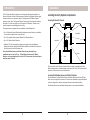
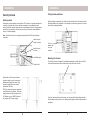
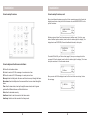
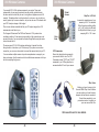
Supervised Security System
Model SC1200
Owner’s Manual
Read This First
Contents
This equipment generates and uses radio
frequency energy, and if not installed and
used properly, that is, in strict accordance
with the manufacturers instructions, may
cause interference to radio and television
reception. It has been type tested and
found to comply with the limits for remote
control security devices in accordance
with the specifications in Sub-Parts B
and C of Part 15 of FCC Rules, which
are designed to provide reasonable
protection against such interference in
a residential installation. However, there
is no guarantee that interference will not
occur in a particular installation. If this
equipment does cause interference to
radio or television reception, which can be
determined by unplugging the equipment,
try to correct the interference by one or
more of the following measures.
This equipment complies with Part 68
of the FCC rules and the requirements
adopted by the ACTA. On the bottom of
this equipment is a label that contains,
among other information, a product
identifier US: B4SAL11B-SC12A. If
requested, this number must be provided
to the telephone company.
Note: The security functions of this system
have not been tested by Underwriters
Laboratories.
• Reorient the antenna of the radio/TV
experiencing the interference.
• Relocate the Console with respect to
the
radio/TV.
• Move the Console away from the radio/
TV.
• Plug the Console into an outlet on a
different electrical circuit from the radio/
TV experiencing the interference.
If necessary, contact www.x10.com for
additional suggestions.
2
Introduction......................................................................................................4
Installation........................................................................................................5
Locating Security System components ........................................................5
Attaching the cables .....................................................................................6
Fitting the backup batteries ..........................................................................7
Wall mounting ...............................................................................................7
Overview...........................................................................................................8
Registering Remotes ..................................................................................12
Registering Door/Window Sensors .............................................................13
Removing Door/Window Sensors ...............................................................14
Installing Door/Window Sensors .................................................................15
Registering Motion Detectors .....................................................................16
Removing Motion Detectors .......................................................................17
Installing Motion Detectors .........................................................................18
Setting the Clock ........................................................................................20
Setting the Phone Numbers .......................................................................21
Setting the Outgoing Message ...................................................................22
Setting the PIN ...........................................................................................24
Clearing the Memory ..................................................................................25
Setting the Options .....................................................................................26
Setting the Delays ......................................................................................27
Setting the Timers ......................................................................................28
Using the System ..........................................................................................32
Arming and Disarming ................................................................................32
Problem zones ............................................................................................33
When there’s an alarm ...............................................................................34
Controlling Lights and Appliances ..............................................................35
Setting up Optional Lamp Modules .............................................................36
Operation from an Outside Telephone ........................................................37
Replacing Batteries .......................................................................................38
Troubleshooting ............................................................................................38
3
Introduction
Installation
The X10 Supervised Security System Console with automatic dialer calls neighbors or
friends in the event of a break in. Battery powered Wireless Door/Window Sensors trigger
the alarm when a door or window is opened. A battery powered RF Motion Detector
protects an indoor area. The Keychain Remote Control is used for arming and disarming
the system. It can also turn lights on and off (requires X10 Modules). All sensors and
remotes incorporate random digital security coding.
Locating Security System components
Locating the Security Console
The system may be configured with any combination of the following items:
• Up to 16 Keychain Security Remotes with arm/disarm and panic functions, and buttons
to control security lights in and around the home.
Dining Room
Hallway
• Up to 30* magnetic switch operated Wireless Door/Window Sensors.
Living Room
• Up to 30* Wireless Motion Detectors.
• Additional X10 Home Automation modules such as plug-in Lamp and Appliance
Modules and wired-in replacement Wall Switch Modules can be added to the system to
flash lights on and off when the alarm trips.
*Note: Door/Window Sensors and Motion Detectors may be added in any
combination up to a total of 30, e.g., 15 Door/Window Sensors and 15 Motion
Detectors, or any combination up to a total of 30. There are also 2 hard wired inputs,
which are zones 31 and 32.
Kitchen
Study
Choose a location for the Security Console which is as central as possible in the house,
while providing access to a modular telephone jack and an AC outlet. The Console may be
placed on a shelf or table, or may be wall mounted.
Locating Door/Window Sensors and Motion Detectors
Plan the location of the Door/Window Sensors and Motion Detectors so that the RF path
which runs in a straight line from sensor to Console is not obstructed by large metal objects
such as a refrigerators or freezers, and passes through as few walls as possible.
Door/Window Sensors may be hidden behind drapes for a more discreet installation.
4
5
Installation
Installation
Security Console
Fitting the backup batteries
Attaching cables
A telephone cord terminated at each end with an RJ11 connector is provided for telephone
connection. If possible, the Console should be connected to its own telephone line to
ensure that the line cannot be busy when the Console attempts to dial out. For applications
where this is not practical, the Console may also share a line with an existing telephone
using a ‘T’ adapter (supplied).
Note: The Security Console is not designed to operate with an RJ31X type telephone
connection.
Attach the power
supply’s cord here.
Attach the phone
cord here.
Hard Wired Inputs.
Tamper Switch
Open the battery compartment cover at the top right hand side of the Console and install 4
AA alkaline batteries (not supplied). It is not necessary to disconnect power to the Console
when fitting or replacing batteries.
Turns on if
batteries are
low or not
installed.
Mounting the Console
The Security Console is designed to be installed freestanding on a table top or shelf. Or it
can be wall mounted using the two slotted holes on the back of the Console.
Open the lid on the Console and attach
the power supply’s cord to the connector
labeled power supply (see above). Plug
the power supply into any convenient
(unswitched) AC outlet.
NOTE: you must use the power supply that
came with the Security System. The power
supply contains circuitry required to control
X10 Modules, so you CANNOT replace it
with a regular 8V DC power supply.
If you don’t want to wall mount the console, you can insert the included rubber plugs into
the two slotted mounting holes so as to tilt the console slightly forward for better viewing of
the display.
6
7
Installation
Installation
Console setup Overview
Console setup Overview, cont.
After you’ve followed the steps on page 6 and 7 and connected power to the Console, the
display shows the time of day at the left of the bottom line, with HOME CONTROL in the
top line. See below:
HOME CONTROL
12:00 am
All features (except Home Control) require access to the Menu mode. To do this, press
either of the Menu up/down buttons (under the lid to the bottom right of the display). The
display then shows ENTER PIN (Personal Identification Number) in the top line.
ENTER PIN
12:00 am
The default PIN is 0000, you’ll find out later (page 24) how you can change this, but for
now press 0000 on the keypad (under the lid to the bottom right of the display). This clears
the top line and shows * for each number entered.
Console keyboard buttons are as follows:
0-9 Used for all number entries.
On Used to send an X10 On message or to enter am in a time.
Off Used to send an X10 Off message or to enter pm in a time.
Menu up Used to initially enter the menu and then to move up through the items.
Menu down Used to initially enter the menu and then to move down through the
items.
Clear Used to clear entries, back up through the menu levels, and to bypass
problem Door/Window Sensors or Motion Detectors.
Enter Used to terminate an entry.
Arm Home Used to arm the console in the Home mode.
Arm Away Used to arm the console in the Away mode.
8
****
12:00 am
When you enter the PIN the display shows the First Level of the menu at step 1, below.
See next page.
1. INSTALL
9
Installation
Installation
First Menu Level
Sub-menus
After pressing a menu up/down button and entering the PIN, the First level menu is
displayed, as shown below:
Once you’ve arrived at your desired first level menu and pressed OK, you can select the
sub-menus under that menu item. Alternatively you can go directly to the sub-menu item
by pressing the appropriate number button.
Phone Numbers Sub-menu
1. INSTALL
To select a menu option, press the up or down Menu button repeatedly to step through the
menu items 1 through 9 below (or you can press the number buttons 1 thru 9 on the control
panel (under the lid to the bottom right of the display) to go directly to that menu item.
Once you arrive at the menu item you desire, press OK to select it.
1.
2.
3.
4.
INSTALL
SET CLOCK
PHONE NUMS
MESSAGE
5. NEW PIN
6. MEMORY
CLEAR
7. OPTIONS
8. DELAYS
9. SET TIMER
Enter number up to 16 digits. Off/pm gives a pause.
PHONE 1
PHONE 2
PHONE 3
PHONE 4
PHONE 5
PHONE 6
Allows installation/removal of sensors, and/or remotes.
Enter time followed by am or pm.
Store up to six (16 digit) phone numbers.
1. RECORD (This is your own alarm message)
2. REPLAY (Replays your message).
Enter new 4 digit PIN.
Clear all Sensors, Remotes, Timers, or Master Clear.
Delays Sub-menu
Set Chime On/Off, Siren On/Off, Set Housecode or Light Code.
Set Exit, Entry, Dial, and Answer Delays.
Enter unit code, then On and Off time, then Daily, Once or Random.
Options Sub-menu
To leave the first level menu press the Clear button. If you are entering numbers (for
the time, etc.), Clear will clear all numbers entered. Otherwise Clear gives the option of
leaving the menu completely and going back to the HOME CONTROL mode, or staying in
the INSTALL mode.
Direct menu
access numbers
Menu buttons
OK button
10
All times are entered in seconds, up to 99.
ENTRY DELAY
EXIT DELAY
DIAL DELAY
ANSWER DELAY
CHIME
SIREN
HOUSECODE
LIGHTCODE
1. CHIME ON
2. CHIME OFF (No chimes when doors/windows are opened)
1. SIREN ON
2. SIREN OFF (Silent Alarm)
Chosen by Menu up/down buttons
Chosen by Menu up/down buttons
Memory Clear Sub-menu
CLEAR ALL
SENSORS
CLEAR ALL
REMOTES
CLEAR ALL
TIMERS
MASTER
RESET
11
Installation
Installation
Initializing Keychain Remotes
Initializing Door/Window Sensors
Press and hold the ARM button on the Keychain remote for 3-4 seconds
and then release it. This initializes the remote and picks a random code
that is used when it is registered with the Console. Note, if the Keychain
remote you purchased is different from shown here, refer to the
installation instructions that came with it.
Remove the screw from the front of the Door/Window Sensor and install
2 AAA alkaline batteries inside. Observe polarity.
Registering the Keychain Remote with the Console
Press either of the Menu up/down buttons (under the lid to the bottom right of the display).
The display then shows ENTER PIN (Personal Identification Number) in the top line.
ENTER PIN
12:00 am
The default PIN is 0000, you’ll find out later (page 24) how you can change this, but for
now press 0000 on the keypad (under the lid to the bottom right of the display). This clears
the top line and shows * for each number entered.
****
12:00 am
This takes you to the first level of the menu at step 1. This is the INSTALLATION level.
When you see INSTALL on the display, press OK. The display then looks like this:
1. INSTALL
ZONE
Now simply press any button on the Keychain remote. The Console acknowledges that it
has been registered by beeping and displaying RMOT 1 SET, RMOT 2 SET, etc., as you
install more remotes.
Repeat this for any other Keychain Remotes you want to register.
Press Clear to back out of the menu. You are asked to confirm, 1. YES, 2 NO. Pressing
1 takes you back to the HOME CONTROL screen. Pressing 2 takes you up one level of
menu.
12
Set switch to MAX (left) for doors, or MIN (right) for windows.
Press and hold the button inside the Sensor for 3-4 seconds and then
release it. This initializes the Sensor and picks a random code that is
used when it is registered with the Console. Replace cover and place
the magnet next to the Sensor (with the arrows aligned).
See pages 14 and 15 if you want to use an additional magnetic contact
switch. Note, if the Sensors you purchased are different from shown
here, refer to the installation instructions that came with them.
Registering Door/Window Sensors with the Console
Press either of the Menu up/down buttons (under the lid to the right of the display). The
display then shows ENTER PIN (Personal Identification Number) in the top line.
ENTER PIN
12:00 am
The default PIN is 0000, you’ll find out later (page 24) how you can change this, but for
now press 0000 on the keypad (under the lid to the bottom right of the display). This clears
the top line and shows * for each number entered.
****
12:00 am
This takes you to the first level of the menu at step 1. This is the INSTALLATION level. The
display looks like this:
1. INSTALL
Press OK and the display looks like this:
1. INSTALL
ZONE
13
Installation
Installation
Now move the magnet away from the Door/Window Sensor. The Console acknowledges
that it has been registered with a chime and by displaying ZONE 1 SET.
Repeat this for any other Door/Window Sensors you want to register. The display
increments to ZONE 2 SET, etc., as you install more Door Window Sensors. If you
connected a second magnetic switch to the contacts on the sensor (as shown on the next
page) move its magnet away to install the second magnetic switch as a separate zone.
Installing the Door/Window Sensors
Note, if the Sensors you purchased are
different from shown here, refer to the
installation instructions that came with them.
*
Ideal location
Two doors or windows
(requires accessory
magnetic switch pair)
If desired, you can specify what zone you want the Door Window Sensor to be registered
into. Just press the number of the zone you want on the Console’s keypad, before you
register the Door Window Sensor.
*
Press Clear to back out of the menu. After a short delay the display reverts to showing
HOME CONTROL on the top line and the time of day on the bottom line.
Removing Door/ Window Sensors
Follow the steps above to install a sensor. Then when the display shows:
1. INSTALL
ZONE
Press the number of the zone you desire (just as if you were going to register the Door/
Window Sensor into that zone) but instead of registering the Door/Window Sensor, press
CLEAR on the Console’s keypad. The display asks you to confirm the deletion:
Sliding window
*
Remove shorting link
before installing hard
wired magnetic contacts.
Note when you add a magnetic switch to a
sensor you can register it with the console
as its own zone, e.g., the sensor itself can
be zone 1 and the extra magnet zone 2.
See previous page.
• Attach the Door/Window Sensor to the wall using the mounting screws provided.
• Fit the Door/Window Sensor as high as possible at the top of the door/window.
CLEAR ZONE
1. YES 2. NO
Pressing 1 on the Console’s keypad changes the display to:
1. INSTALL
ZONE 13 OUT
Where 13 is the zone you selected. Pressing 2 instead takes you back to the INSTALL
ZONE screen.
Press Clear to back out of the menu. You are asked to confirm, 1. YES, 2 NO. Pressing
1 takes you back to the HOME CONTROL screen. Pressing 2 takes you up one level of
menu.
14
• Make sure the arrows on the magnetic and the Door/Window Sensor are facing each
other and that they separate cleanly when the door or window is opened.
• To protect two doors or windows close to each other, use the Door/Window Sensor with
an additional set of magnetic switch contacts as shown in the diagrams above.
• Set the DELAY slide switch (inside the Sensor) to MIN to always trigger the alarm
instantly (for windows), or to MAX to trigger the alarm after a preset entry delay when the
system is armed in the AWAY mode (for doors).
The numbers 1 – 32 in the display refer to up to 32 “zones.” These represent up to 30
Door/Window Sensors and/or Motion Detectors you install, plus the 2 hard wired zones.
The numbers show open zones, problem zones and bypassed zones by being displayed
as steady on (door or window open), slow flash (there’s a problem with that zone) or fast
flash (that zone has been bypassed). Attempting to arm with an open or problem zone
makes the Console beep continuously and it will display in words on the display what the
cause is, but only for one zone at a time. Bypassing that zone (by pressing the Clear
button) moves on to the next problem zone, if there is one.
15
Installation
Installation
Initializing Motion Detectors
Remove the cover on the front of the Motion Detector and install 2
AAA alkaline batteries in the compartment. Replace the cover.
Press and hold the TEST button on the back of the Motion Detector
for 3-4 seconds and then release it. This initializes the Motion
Detector and picks a random code that is used when it is registered
with the Console. Place the unit face down, so that it won’t see any
motion during the registering process below. Note, if the Motion
Detectors you purchased are different from shown here, refer to
the installation instructions that came with them.
Registering the Motion Detector with the Console
Press either of the Menu up/down buttons (under the lid to the right of the display). The
display then shows ENTER PIN (Personal Identification Number) in the top line.
ENTER PIN
12:00 am
The default PIN is 0000, you’ll find out later (page 24) how you can change this, but for
now press 0000 on the keypad (under the lid to the bottom right of the display). This clears
the top line and shows * for each number entered.
****
12:00 am
Now simply press the TEST button on the back of the Motion Detector (or turn the unit
over so that it sees motion). The Console will acknowledge that it has been registered by
displaying (for example) ZONE 3 SET.
Repeat this for any other Motion Detectors you want to register. The display increments to
ZONE 4 SET, etc., as you install more Motion Detectors.
If desired, you can specify what zone you want the Motion Detector to be installed into.
Just press the number of the zone you want on the Console’s keypad, before you press the
TEST button on the back of the Motion Detector.
Press Clear to back out of the menu. You are asked to confirm, 1. YES, 2 NO. Pressing
1 takes you back to the HOME CONTROL screen. Pressing 2 take you up one level of
menu.
Removing Motion Detectors
Follow the steps above to install a Motion Detector. When the display shows:
1. INSTALL
ZONE
Press the number of the zone you desire (just as if you were going to register the Motion
Detector into that zone) but instead of pressing the TEST button on the Motion Detector
(to register it) press CLEAR on the Console’s keypad. The display ask you to confirm the
deletion:
CLEAR ZONE
1. YES 2. NO
This takes you to the first level of the menu at step 1. This is the INSTALLATION level. The
display looks like this:
1. INSTALL
Press OK and the display looks like this:
Pressing 1 on the Console’s keypad changes the display to:
1. INSTALL
ZONE 13 OUT
Where 13 is the zone you selected. Pressing 2 instead takes you back to the INSTALL
ZONE screen.
1. INSTALL
ZONE
16
Press Clear to back out of the menu. You are asked to confirm, 1. YES, 2 NO. Pressing
1 takes you back to the HOME CONTROL screen. Pressing 2 takes you up one level of
menu.
17
Installation
Installation
Installing the Motion Detector
Hard-Wired Inputs
You can also connect two hard-wired magnetic contact switches to the console.
• Attach the Motion Detector to a wall at a height of 5 to 6 ft. using the mounting bracket
and screws provided.
• Point the Motion Detector so that it looks slightly downwards.
• Set the slide switch (on the back) to position 1 for instant triggering for maximum
sensitivity or position 2 to trigger only after two movements have been sensed.
90°
OR
ECT
N DET
TIO
MO
These will be zones 31 and 32.
5-6ft
30-40ft
Tamper switch (under lid). Note,
some models do not have a
tamper switch. See note at top of
page 16.
You can install a total of 30 additional zones, which can be a combination of Door/Window
Sensors and Motion Detectors. So, for example, you could have 15 Door/Window Sensors,
15 Motion Detectors, and 2 hard-wired zones. The hard wired zones are treated as delayed
zones (i.e. they have exit and entry delays if you arm the system in the Away mode).
Magnetic Switch
Contacts sold
separately
Remove shorting link
before installing hard
wired magnetic contacts.
Testing the Motion Detector
• Set the slide switch on the Motion Detector to position 1.
• Press and hold the TEST button for about a second (until
the LED flashes twice) and then release it.
• Wait 20 seconds for the Motion Detector to settle.
• Walk in front of the Motion Detector. The indicator LED
lights each time it senses movement. Check the coverage
area and reposition the sensor as required.
• Press the TEST button to return to normal operating
mode.
Note: The Motion Detector will automatically return to
normal operating mode after about 2 minutes.
18
19
Installation
Installation
Setting the Clock
Setting the phone numbers
Press either of the Menu up/down buttons (under the lid to the bottom right of the display).
The display then shows ENTER PIN (Personal Identification Number) in the top line.
Press either of the Menu up/down buttons (under the lid to the bottom right of the display).
The display then shows ENTER PIN (Personal Identification Number) in the top line.
ENTER PIN
12:00 am
The default PIN is 0000, you’ll find out later (page 24) how you can change this, but for
now press 0000 on the keypad (under the lid to the bottom right of the display). This clears
the top line and shows * for each number entered.
ENTER PIN
12:00 am
The default PIN is 0000, you’ll find out later (page 24) how you can change this, but for
now press 0000 on the keypad (under the lid to the bottom right of the display). This clears
the top line and shows * for each number entered.
****
12:00 am
****
12:00 am
This takes you to the first level of the menu at step 1. This is the INSTALLATION level. The
display looks like this:
1. INSTALL
This takes you to the first level of the menu at step 1. This is the INSTALLATION level. The
display looks like this:
1. INSTALL
Press an up or down menu button until you reach the PHONE NUMS menu, and then
press OK to go to the screen below (or press 3 to go into the PHONE NUMS menu ):
3. PHONE NUMS
Press an up or down menu button until you reach the SET CLOCK menu, and then press
OK (or press 2 to go directly to the screen below):
2. SET CLOCK
4:00 pm
Enter the time by pressing the digits on the Console’s keyboard. Then press am or pm.
Then press OK.
Press Clear to back out of the menu. If you press Clear while entering numbers, before
you’re finished setting the clock, it clears the numbers. If you press Clear after you’ve set
the time and pressed OK, you are asked to confirm, 1. YES, 2 NO. Pressing 1 takes you
back to the HOME CONTROL screen. Pressing 2 stays in INSTALL mode.
20
Press an up or down Menu button to select the desired sub-menu:
PHONE 1
PHONE 2
PHONE 3
PHONE 4
PHONE 5
PHONE 6
Press OK at the desired number (1-6). The display shows SET PH1, SET PH2, etc. Enter
the phone number, up to 16 digits. off/pm gives a pause. Press OK. This takes you to the
next phone number to be stored.
Press Clear to back out of the menu. If you press Clear while entering numbers, before
you’ve finished setting the phone number, it clears the numbers. If you press Clear after
you finished entering the phone number and pressed OK, you are asked to confirm, 1.
YES, 2 NO. Pressing 1 takes you back to the HOME CONTROL screen. Pressing 2 stays
in INSTALL mode.
21
Installation
Installation
Recording your outgoing phone message
Press 1 for RECORD , then press OK. The display shows:
Press either of the Menu up/down buttons (under the lid to the bottom right of the display).
The display then shows ENTER PIN (Personal Identification Number) in the top line.
ENTER PIN
12:00 am
PLEASE WAIT
Then:
SPEAK NOW
The default PIN is 0000, you’ll find out later (page 24) how you can change this, but for
now press 0000 on the keypad (under the lid to the bottom right of the display). This clears
the top line and shows * for each number entered.
****
12:00 am
This takes you to the first level of the menu at step 1. This is the INSTALLATION level. The
display looks like this:
1. INSTALL
Press an up or down menu button until you reach the MESSAGE menu, and then press
OK to go to the screen below (or press 4 to go into the MESSAGE menu ):
4. MESSAGE
Press 1 or 2 to select one of the options below:
1. RECORD
2. REPLAY
Clearly speak your message into the Console’s microphone (up to 12 seconds max.).
A typical message could be: “There’s an alarm in progress at (your address), at the end of
this message please press any button on your touch-tone phone to listen in.” After you’ve
finished speaking (12 seconds max), wait for the display shown below:
1. RECORD
2. REPLAY
Now press 2 for REPLAY the display shows:
PLEASE WAIT
It then plays back your recorded message. Wait for the display shown below:
1. RECORD
2. REPLAY
Press Clear to back out of the menu. You are asked to confirm, 1. YES, 2 NO. Pressing 1
takes you back to the HOME CONTROL screen. Pressing 2 stays in the INSTALL mode.
Note: you cannot record messages remotely via telephone.
1. RECORD (This is your own alarm message).
2. REPLAY (This replays a previously recorded message).
22
23
Installation
Installation
Changing your Personal Identification Number (PIN)
Clearing the memory
Press either of the Menu up/down buttons (under the lid to the bottom right of the display).
The display then shows ENTER PIN (Personal Identification Number) in the top line.
Press either of the Menu up/down buttons (under the lid to the bottom right of the display).
The display then shows ENTER PIN (Personal Identification Number) in the top line.
ENTER PIN
12:00 am
ENTER PIN
12:00 am
The default PIN is 0000, so press 0000 on the keypad (under the lid to the bottom right of
the display). This clears the top line and shows * for each number entered.
The default PIN is 0000, you’ll find out later (page 24) how you can change this, but for
now press 0000 on the keypad (under the lid to the bottom right of the display). This clears
the top line and shows * for each number entered.
****
12:00 am
This takes you to the first level of the menu at step 1. This is the INSTALLATION level. The
display looks like this:
****
12:00 am
This takes you to the first level of the menu at step 1. This is the INSTALLATION level. The
display looks like this:
1. INSTALL
1. INSTALL
Press an up or down menu button until you reach the NEW PIN menu, and then press OK
(or press 5 to go directly to the screen below):
Press an up or down menu button until you reach the MEMORY CLEAR menu, and then
press OK to go to the screen below (or press 6 to go into the MEMORY CLEAR menu ):
6. MEMORY
CLEAR
5. NEW PIN
Press an up or down Menu button to select the desired sub-menu.
Enter your new PIN (4 digits). Press OK.
Note, choose a PIN that you are not likely to forget (a birthday, for example). If you forget
your PIN you will not be able use the system. If you do forget your PIN contact www.x10.
com to find out how to reset your system.
CLEAR ALL SENSORS
CLEAR ALL REMOTES
CLEAR ALL TIMERS
MASTER RESET
Press Clear to back out of the menu. If you press Clear while entering numbers, before
you’re finished setting the new PIN, it clears the numbers. If you press Clear after you’ve
set the new PIN and pressed OK, you are asked to confirm, 1. YES, 2 NO. Pressing 1
takes you back to the HOME CONTROL screen. Pressing 2 stays in INSTALL mode.
Select the desired sub-menu item and then press OK. Press Clear to back out of the
menu. You are asked to confirm, 1. YES, 2 NO. Pressing 1 takes you back to the HOME
CONTROL screen. Pressing 2 stays in the MEMORY CLEAR menu. Note, selecting 4.
MASTER RESET immediately takes you back to the HOME CONTROL screen.
24
25
Installation
Installation
Setting Options
Setting Delays
Press either of the Menu up/down buttons (under the lid to the bottom right of the display).
The display then shows ENTER PIN (Personal Identification Number) in the top line.
Press either of the Menu up/down buttons (under the lid to the bottom right of the display).
The display then shows ENTER PIN (Personal Identification Number) in the top line.
ENTER PIN
12:00 am
The default PIN is 0000, you’ll find out later (page 24) how you can change this, but for
now press 0000 on the keypad (under the lid to the bottom right of the display). This clears
the top line and shows * for each number entered.
****
12:00 am
This takes you to the first level of the menu at step 1. This is the INSTALLATION level. The
display looks like this:
1. INSTALL
Press an up or down menu button until you reach the OPTIONS menu, and then press OK
to go to the screen below (or press 7 to go into the OPTIONS menu ):
7. OPTIONS
ENTER PIN
12:00 am
The default PIN is 0000, you’ll find out later (page 24) how you can change this, but for
now press 0000 on the keypad (under the lid to the bottom right of the display). This clears
the top line and shows * for each number entered.
****
12:00 am
This takes you to the first level of the menu at step 1. This is the INSTALLATION level. The
display looks like this:
1. INSTALL
Press an up or down menu button until you reach the DELAYS menu, and then press OK
to go to the screen below (or press 8 to go into the DELAYS menu ):
8. DELAYS
Press an up or down Menu button to select the desired sub-menu:
Press the up or down Menu button to select the desired sub-menu:
CHIME
ENTRY DELAY
(Default 30 seconds)
EXIT DELAY
(Default 60 seconds)
DIAL DELAY
(Default 5 seconds)
ANSWER DELAY
(Default 30 seconds)
Select the desired sub-menu item and then press OK. Then enter the desired delay time in
seconds up to 99. Press OK.
1. CHIME ON
2. CHIME OFF (No chimes when doors/windows are opened)
SIREN
1. SIREN ON
2. SIREN OFF (Silent Alarm)
HOUSECODE
(Chosen by Menu up/down buttons)
LIGHTCODE
(Chosen by Menu up/down buttons)
Select the desired sub-menu item and then press OK. Press 1 or 2 in CHIME and SIREN
sub-menus. Select the desired Housecode letter, or desired Security Light Code, using
the up/down buttons. Press OK. Press Clear to back out of the menu. You are asked
to confirm, 1. YES, 2 NO. Pressing 1 takes you back to the HOME CONTROL screen.
Pressing 2 stays in INSTALL mode.
26
Press Clear to back out of the menu. You are asked to confirm, 1. YES, 2 NO. Pressing
1 takes you back to the HOME CONTROL screen. Pressing 2 stays in INSTALL mode.
Pressing Clear while entering a number (for a delay time) just clears the numbers.
27
Installation
Installation
Setting Timers
Press either of the Menu up/down buttons (under the lid to the bottom right of the display).
The display then shows ENTER PIN (Personal Identification Number) in the top line.
ENTER PIN
12:00 am
The default PIN is 0000, you’ll find out later (page 24) how you can change this, but for
now press 0000 on the keypad (under the lid to the bottom right of the display). This clears
the top line and shows * for each number entered.
****
12:00 am
This takes you to the first level of the menu at step 1. This is the INSTALLATION level. The
display looks like this:
To enter a new timer you must be on the NEW TIMER screen. Then press OK. The display
shows UNIT NUMBER on the top line. Using the number keys, enter a valid number (1-16)
and press OK.
9. UNIT NUMBER
Say for example you enter 12. The top line displays TIMER 12 ON. The bottom line
displays a colon, :
9. TIMER 12 ON
:
Enter your desired ON time with the number keys followed by am or pm in the format
shown below, (or just press OK if you don’t want to set an ON time). Press Clear if you
enter a wrong time.
9. TIMER 12 ON
12:34am
Then press OK. The top line displays TIMER 12 OFF. The bottom line displays a colon, :
1. INSTALL
9. TIMER 12 OFF
:
Press an up or down menu button until you reach the SET TIMER menu, and then press
OK to go to the screen below (or press 9 to go to the NEW TIMER menu):
9. SET TIMER
Enter the OFF time as above and press OK, (or just press OK if you don’t want to set an
OFF time). Press Clear if you enter a wrong time. The display shows 1. DAILY on the
bottom line (top line blank).
1. DAILY
You will see NEW TIMER on the top line. If no timers have yet been entered the up and
down Menu buttons will do nothing. If there are other timers already in memory the up and
down buttons will cycle around them and will always include NEW TIMER in the loop if
there is empty space in the memory.
9. NEW TIMER
Using the up or down Menu buttons you can cycle around 1. DAILY, 2. ONCE ONLY, and
3. RANDOM. Select the one of your choice and press OK. The display again shows NEW
TIMER. Now the up and down Menu buttons will cycle through the entered events in the
form
12ON 12:34am
OFF 12:45pm
Note you can set a total of 12 “timer pairs” i.e. ON-OFF times. If you choose to set an ON
time with no corresponding OFF time for that unit code (or vice versa) it still counts as a
“timer pair.” RANDOM varies the time during the programmed hour.
28
29
Installation
Installation
Reviewing/Canceling Timers
You can cycle through (Review) your stored timers by pressing the up or down Menu
buttons. This will show the stored timers in the form below
Press either of the Menu up/down buttons (under the lid to the bottom right of the display).
The display then shows ENTER PIN (Personal Identification Number) in the top line.
12ON 12:34am
OFF 12:45pm
ENTER PIN
12:00 am
The default PIN is 0000, you’ll find out later (page 24) how you can change this, but for
now press 0000 on the keypad (under the lid to the bottom right of the display). This clears
the top line and shows * for each number entered.
****
12:00 am
This takes you to the first level of the menu at step 1. This is the INSTALLATION level. The
display looks like this:
1. INSTALL
While a timer is on the display, pressing Clear deletes it. You are first asked: CLEAR
TIMER 1. YES 2. NO .
9. CLEAR TIMER
1. YES 2. NO
Pressing 1 (for YES) deletes the timer and takes you to NEW TIMER to allow you to start
entering a new timer. Pressing 2 takes you to NEW TIMER without deleting the one that
was on the screen. Press Clear to back out of the Menus.
Replacing Timers
You can cycle through (Review) your timers by pressing the up or down Menu buttons.
This will show the stored timers in the form below
12ON 12:34am
OFF 12:45pm
While a timer is on the display, pressing OK takes you to the Replace Timer screen below.
Press an up or down menu button until you reach the SET TIMER menu, and then press
OK to go to the screen below (or press 9 to go into the SET TIMER menu ):
9. REPLACE TIMR
1. YES 2. NO
9. SET TIMER
You will see NEW TIMER on the top line. If no timers have yet been entered the up and
down Menu buttons will do nothing. If there are other timers already in memory the up and
down buttons will cycle around them and will always include NEW TIMER in the loop if
there is empty space in the memory.
Selecting 1 for YES, takes you to the UNIT NUMBER screen below where you can
continue to enter a new timer as described on page 29. Selecting 2 for NO takes you to the
NEW TIMER screen so you can enter a new timer without replacing the existing one. Press
Clear the back out of the menus.
9. UNIT NUMBER
9. NEW TIMER
Note you can also clear ALL timers as described on page 25.
30
31
Using the system
Using the system
Arming the system
If there’s a problem
Press ARM HOME on the Console to arm all Door/Window Sensors instantly. Motion
Detectors will not trip the system when it is armed in the ARM HOME mode.
If a door or window is open and you try to arm the system the display looks as below.
Where ZONE 9 is the door or window that’s open.
Press ARM AWAY to arm all Door/Window Sensors and Motion Detectors. This arms the
system after a set delay. The delay will be what you specified as the EXIT DELAY on page
27 (1 minute default). If you arm the system in the AWAY mode you will also have an entry
delay when you enter your home before the alarm trips, to give you time to disarm it. This
delay will be what you specified for your ENTRY DELAY on page 27 (30 second default).
Pressing ARM on the Keychain remote always arms in the AWAY mode, but arms
instantly.
Disarming the system
OPEN
ZONE 9
If a Door/Window Sensor or Motion Detector has not reported in within the last 4 hours
and you try to arm the system the display shows:
PROBLEM
ZONE 9
Pressing DISARM on the Keychain remote disarms the system instantly. The zone that
was violated is shown in the display. To remove this press Arm and Disarm again.
To disarm from the Console: Enter your 4 digit PIN (Personal Identification Number) this
will be 0000 unless you changed it (see page 24).
If a Door/Window Sensor has been tampered with, e.g. the cover is open, and you try to
arm the system the display shows:
TAMPER
ZONE 9
ENTER PIN
12:00 am
Entering the PIN clears the top line and shows * for each number entered.
****
12:00 am
If the unit was armed, (in either ARMED HOME or ARMED AWAY modes) it will disarm
when the PIN is entered, and return to the time display, with DISARMED in the top line.
DISARMED
32
For all the above situations, pressing the Clear (Bypass) button bypasses the problem
zone and lets you arm the system. After pressing Bypass the next problem zone is
displayed, (if there is more than one).
You can’t arm the system while there’s a problem zone unless you fix the problem, or
bypass the zone. If you try to arm the system while there’s a problem with one or more
zone you will hear a repetitive “trouble alarm” to alert you that you need to bypass or fix
the problem zone(s).
Note also, if the Console itself has been tampered with, i.e. the door to the upper right of
the display is open, the problem must be fixed (close the door) before you can arm the
system. Note if the system is armed and this door is tampered with, the alarm trips.
If you bypass a zone and then arm the system, that zone stays bypassed until you disarm
the system.
33
Using the system
Controlling Lights and Appliances
When there’s an alarm
When the system is armed (in Home or Away mode) and you open a protected door or
window, or walk past a Motion Detector (if armed in the Away Mode), or activate the Panic
feature (by pressing Arm and Disarm at the same time on the Key Chain Remote) the
alarm trips. The following then happens:
A loud siren sounds.
Lights (set to the two security codes) flash on and off (if you set up X10 Modules). See
page 36.
The Console dials the first phone number you set up. It then starts to play the recorded
message you stored. E.G. “There’s an alarm in progress at (your address), at the end of
this message please press any button on your touch-tone phone to listen in.” Note, it might
take a while before the person the Console called picks up the phone so they might miss
the first part of your message, but the message is repeated 3 times, so they will get to hear
the complete message.
When the person who was called answers the call and presses a button on their phone this
activates a microphone in the Console and they will be able to listen in to you home, and
will be able to determine if there is suspicious activity going on. They can then take action.
E.G. call the Police for you.
IMPORTANT: Do NOT program the Console to call the Police directly.
NOTES:
The person who answers the phone needs to wait for a gap between the messages before
they can press a button on their phone to listen in (the message repeats three times, but
might have already played once or twice before the person answers the phone).
If no one answers the call (and presses a button on their phone) before the third message
is played, the Console dials the next number stored. It can take quite a long time to dial all
the numbers if you’ve stored 6 of them, and no one answers. But the siren stops sounding
after 4 minutes in any case (the unit still dials all the numbers stored unless someone
answers the call (and presses a button on their phone).
If you install one or more Lamp Modules (sold separately), see next page, you can control
lights around your home from the Console. When the Console is in its normal state it
displays HOME CONTROL in the display. When its in this state you can simply press the
number button on the Console corresponding to the number set on the module and then
press On or Off on the Console’s control panel to control the light connected to the module.
You can also control lights set to your Security LIGHTCODEs from the A and B buttons on
the Key Chain Remote. The A buttons on the Key Chain Remote control lights connected
to X10 Modules that are set to the Security LIGHTCODE you set in the Console. (See step
4 on page 26). The B buttons control modules set to the next sequential number. I.E. if you
set your Security LIGHTCODE to 1, the A and B buttons on the Key Chain Remote will
control X10 Modules that are set to Unit Codes 1 and 2. If your Security LIGHTCODE is
10, the A and B buttons will control Modules 10 and 11. If your Security LIGHTCODE to 16,
the A and B buttons will control 16 and 1, etc.
Any lights set to your two Security LIGHTCODEs flash on and off when the alarm trips.
They stay on after an alarm until you turn them off, either from the Console, or from the
Key Chain Remote.
These lights also blink on for a second when the alarm is armed in the HOME Mode, or
turn on for the exit delay time when the alarm is armed in the AWAY Mode.
Refer to either version below depending on which version you purchased.
Pressing both PANIC buttons at the
same time activates the panic alarm,
even if the Console is not armed.
LIGHTS ON/OFF control lights
connected to X10 Modules that are
set to the Security LIGHT CODE you
set in the Console (see page 26).
If the system is tampered with
BATTERY
ARM
PANIC
DISARM
LIGHTS
ON
LIGHTS
OFF
If the system is armed and someone tampers with (opens the cover) on a Door/Window
Sensor or the Console, the same thing happens as when the alarm is tripped by any
other method. If the system is NOT armed and someone tampers with a Sensor or the
Console, the word TAMPER appears in the display but the system does not trip. You must
fix the tamper before you can arm the system. Press Arm then Disarm to remove the word
TAMPER from the display.
34
35
Optional Lamp Modules
Operation from an Outside Telephone
Setting the (optional) Lamp
Module’s Code
UNIT CODE
DIAL
The Console has remote telephone access, with voice responses to acknowledge receipt
of remote commands.
When you call home, the Console answers and says “Please enter PIN.” You enter your
PIN using the touch tone buttons on the remote telephone.
Using a small screwdriver, set the red
House Code dial to the same letter as
your Console is set to. Set the Black Unit
Code dial to any unused number.
If the PIN is entered correctly it says “PIN accepted”. If wrong it says “Error.”
HOUSE CODE
DIAL
Pressing 0, then * (on the remote telephone’s touch tone keypad) arms the Console.
Pressing 0, then # disarms the Console.
Ratings
Pressing 9, then 9, then * tells you the current system status: I.E. it says Armed Home,
Armed away, Disarmed, Panic alarm, or Alarm in zone (1 – 32).
The Lamp Module can be used to control an incandescent lamp rated up to 300W. It is not
suitable for other types of lamps such as fluorescent or energy saving lamps, low voltage
lamps, or lamps that include a dimmer control. Caution: Do not connect an appliance
such as a coffee pot or heater to a Lamp Module. It may damage the Module and/or the
appliance and could cause a fire hazard. Use an Appliance Module instead.
The numbers 1 – 32 in the display refer to up to 32 “zones.” These represent the Door/
Window Sensors and/or Motion Detectors you installed. Therefore if the alarm tripped
because zone 3 was violated, when you call in and press 9, 9, * you will hear “Alarm in
zone 3.”
Remotely controlling lights (or appliances) via telephone
If you install one or more X10 Modules (sold separately), see previous page, you can
control lights and appliances around your home from any touch tone telephone in the
world.
1.
Set the House Code
and Unit Code.
2.
Plug a lamp into
the Module.
3.
Plug the Module into
the same wall outlet
as your controller (see
testing below).
When you call home, the Console answers and says “Please enter PIN.”
If the PIN is entered correctly it says “PIN accepted”. If wrong it says “Error.”
If you then press 4, then * on the touch tone phone, it says “4 On” and turns on any X10
Module(s) set to Unit Code 4 (and the same Housecode as the Console is set to).
If you then press 1, then 6, then # on the touch tone phone, it says “16 Off” and turns off
any X10 Module(s) set to Unit Code 16 (and the same Housecode as the Console is set
to).
If you own an answering machine.
Testing The Module
Make sure the lamp’s switch is on. Plug the Module into the same wall outlet as your
Console’s power supply, press the On and Off buttons on the Console that correspond to
the Unit Code setting on the Module. If the Module turns on and off you can unplug the
Module and move it to its permanent location.
If you can’t control the module, visit www.x10.com for help.
36
If you own an answering machine, you will normally set it to answer after a few rings.
In this case, when the answering machine answers a call (or if there’s someone home
who picks up the phone), the security system will NOT answer the call and will NOT
say “Please enter PIN.” You can still however go ahead and enter the PIN to access
the security system features above. Just wait until your answering machine finishes its
outgoing message and then enter your security system PIN. Note, your answering machine
will record the touch tones you hear when you press buttons to turn lights on and off, etc.,
and will also record the messages played back by the security system.
37
Battery Information
Battery Information
General
Door/Window Sensors and Motion Detectors
Door/Window Sensors, Motion Detectors and Keychain remotes are designed to operate
for approximately one year when fitted with the appropriate batteries. Since operating
conditions vary from installation to installation however, it is recommended that all batteries
are replaced every 6 months.
Battery Replacement
Security Console
Battery backup
The batteries in the Security Console are used as a backup when there has been a power
failure. The batteries provides approximately 12 hours of backup time provided the alarm
has not been triggered.
While on battery backup, the Console will continue to operate, and will sound the siren and
dial out if the alarm is tripped. It will not, of course, flash the house lights (because there’s
no AC power).
If both the AC supply and the batteries fail, the Console will no longer dial out or sound the
siren. You will not lose its telephone numbers, recorded message, or installed sensors and
remotes, but you will need to reset the clock for the correct time of day.
Battery Replacement
Batteries can be replaced at any time, even while the unit is powered up. There is no
special procedure for battery replacement. Use 4 AA alkaline batteries.
If a zone has not reported in to the Console during the last four hours, the display will show
PROBLEM and the appropriate zone number when you try to arm the system. This is most
likely caused by dead batteries in the Motion Detector or Door/Window Sensor for that
zone.
As with the remotes, as long as the batteries have not completely failed they may be
replaced with fresh batteries without the need to reinstall the Motion Detector or Door/
Window Sensor. After removing the old batteries the new batteries must be fitted within 30
seconds to ensure that the code is retained.
Testing the Door/Window Sensor
Once the batteries have been replaced, the Door/Window Sensor should be tested as
follows:
• Make sure the system is NOT armed.
• Open the door or window with the sensor attached. The Console chimes to acknowledge
and the zone # is displayed on the LCD.
• If you don’t hear a chime, reregister the Door/Window Sensor, as described on page 13
Testing the Motion Sensor
Keychain Remotes
To test the Motion Detector:
Battery Replacement
• Make sure the system is armed.
Providing the batteries have not already failed, they can be replaced with fresh batteries
without the need to reregister the remote. After removing the old batteries fresh batteries
must be fitted within 30 seconds to ensure that the security code is retained.
• Press the TEST button on the back of the Motion Detector. The alarm trips. Press disarm
on the Keychain Remote.
Gently pry the 2 halves of the Keychain Remote’s case apart and install two CR2016
lithium batteries in the compartment (+ facing up). Press the 2 halves of the cabinet back
together.
Once the batteries have been replaced, confirm that the remote is still registered with the
Console by arming the system. If it does not arm, the code has been lost and you will need
to proceed as described below.
If the batteries have failed completely, the remote’s code will have been lost. The remote
will need to be reinstalled following the procedure on page 12.
38
• If the alarm doesn’t trip, reregister the Motion Detector, as described on page 16.
Clearing Remotes & Sensors from the Console
If you suspect that a neighbor’s system is causing false alarms, or if you need to reinstall
remotes, Door/Window Sensors, and Motion Detectors for any other reason, you can
clear all sensors and remotes from the Console’s memory by following the steps on page
25. Before reregistering your remotes, Door/Window Sensors, and Motion Detectors you
should reinitialize them - remove the batteries, press a button for 5 seconds then refit the
batteries. Then follow the steps to reinitialize the unit (pages 12, 13, or 16 as appropriate).
39
Troubleshooting
Troubleshooting
PROBLEM
SOLUTION
If the system does not arm.
• Check that the indicator on the Remote
turns on when you press ARM.
Replace the batteries and reregister the
Remote with the Console if necessary.
PROBLEM
SOLUTION
If you hear a repetitive trouble alarm when
you try to arm the system, and it does not
arm.
Check the Console’s display. If a door or
window is open, its zone # will indicate
there’s a PROBLEM.
• Press DISARM. Check each Door/
Window Sensor is working properly and
that no doors or windows are open.
Then arm the system.
Or:
Console displays PROBLEM followed by
Zone number when you try to arm it.
• While the trouble alarm is sounding,
press CLEAR on the Console to
bypass the problem zone (the display
shows that it has been BYPASSED).
Then arm the system again.
One of the sensors/motion detectors has
not reported in, in the last 4 hours.
Check that the batteries in the sensor/
motion detector are good.
Or a protected door or window is open.
• Or if the display shows TAMPER,
check the cover on the Door/ Window
Sensor for that zone.
If you need to arm the system and want to
ignore a sensor/motion detector which is
not functioning:
• Or check that the upper right lid on the
Console it closed.
1. Press CLEAR on the Console while the
problems is being displayed.
2. Then press ARM on the Remote. The
problem zone is not protected but all
other zones are armed.
If the alarm trips when you enter the
house before you have time to disarm it.
Arm the system in the AWAY mode.
Lights will not turn on or off from the ON or
OFF buttons on the Keychain Remote.
• Be sure you set the correct SECURITY
LIGHT Code in the Console, see pages
26 and 35.
• Be sure the light you are trying to
control has its on/off switch in the on
position. Be sure its bulb is good.
• Plug the Module into another outlet
near the Console.
• Check that the indicator on the Remote
comes on when you press a button.
Replace batteries and reregister remote
if necessary.
• Check the dials on the Modules.
40
41
Troubleshooting
Troubleshooting
PROBLEM
SOLUTION
You open a door or window and the alarm
does not trip.
• Check that the system is armed.
• Check to see if the alarm trips when
you press TEST inside the Door/
Window Sensor.
PROBLEM
SOLUTION
If you do not hear a beep from the
Console when you register a Door/
Window Sensor or Motion Detector.
With the Console NOT armed check that
it chimes when you press TEST on the
Door/Window Sensor, or the alarm trips
when you press test on a Motion Detector
(when the system IS armed). If it does,
then the sensor is already installed and no
further action is necessary. If not:
• If the alarm does not trip when you
press TEST, check that the indicator on
the sensor comes on when you press
TEST.
If the indicator does not come on, replace
the batteries and reinstall the sensor if
necessary.
The system flashes lights by repetitively
transmitting the SECURITY light on and
off codes.
If appliances turn off during an alarm.
• Reregister the sensor/motion detector
(see Setting Up Door/Window Sensors
and Setting Up Motion Detectors.
If the battery indicator on the Console is
on.
Replace the Console’s batteries. Four AA
alkaline batteries provides approximately
12 hours of backup. Replace batteries at
least once a year.
If you lose your remote control.
Reinstall your complete system to prevent
someone else from using the lost remote
control. See bottom of page 39.
If the system Arms or Disarms by itself
A neighbor may have a compatible
system. Reinstall the complete system so
that it chooses different RF codes. See
bottom of page 39.
If the light on the Keychain Remote stays
on during initialization.
Remove the batteries, press a button
for a few seconds, release, then replace
the batteries. Press and hold the ARM
button on the Keychain Remote for a
few seconds and then release it. This
initializes the remote and picks a random
code that is used when it is registered with
the Console. Reregister the remote.
Any Appliance Modules set to the same
codes will therefore turn on and off.
If you do not hear a beep from the
Console when you press ARM to install a
Remote.
• Re-initialize the remote (see page 12).
42
43
Troubleshooting
LIMITED ONE YEAR WARRANTY
PROBLEM
SOLUTION
The alarm cause is shown on the display
even after disarming.
To remove, Arm and Disarm from a
remote, or disarm by pressing a menu key
and entering the PIN on the Console.
If the optional PowerHorn does not trip
when the alarm trips.
• Be sure you set the dials on the
PowerHorn to the same SECURITY
LIGHT code as set in the Console.
• Plug the PowerHorn into another outlet
near the Console.
X10 Wireless Technology, Inc. Limited One Year Warranty
X10.com, a division of X10 Wireless Technology, Inc. (X10) warrants X10
products to be free from defective material and workmanship for a period of
one (1) year from the original date of purchase at retail. X10 agrees to repair
or replace, at its sole discretion, a defective X10 product if returned to X10
within the warranty period and with proof of purchase. If service is required
under this warranty:
Call 1-800-442-5065, visit www.x10.com, or e-mail [email protected].
For help or more information on setup, please visit:
The Motion Detector causes false alarms.
• All brands of motion detectors sense
motion by detecting a change in
temperature, therefore do not place
the detector near any sources of heat
such as over a heating vent or an air
conditioner.
www.x10.com/support
• Do not place in a direct source of bright
light, such as sunlight.
Special Note
Intercom Systems
Intercom systems which send voice signals over existing electrical wiring may interfere
with the ability to control modules from your security system with the intercom in use. If the
intercom system has its own separate wiring it will not cause a problem.
44
45
Expanding Your System
Expanding Your System
The X10 Security System can flash lights on and off when the alarm trips. You connect
the lights you want it to control to X10 Lamp Modules and Wall Switch Modules (sold
separately). The Security Console also acts as a “Transceiver” and passes commands
received from wireless remote controls onto your house wiring, so you can use X10
wireless remote controls to control the same lights that the Security System flashes. You
can also use the X10 remote controls to control Appliance Modules, etc.
The Security Console also works with X10 EagleEye and ActiveEye wireless motion
sensors, again acting as a Transceiver, to pass the commands from the motion sensors to
the X10 Modules. The modules and controllers illustrated below represent just a few of the
wide range of X10 modules you can choose from to expand your Security System.
Control an incandescent ceiling light, closet light, etc., with the convenient Screwin Lamp Module LM15A.
R e p l a c e existing AC wall outlets with the Receptacle Module SR227. Has
one 15A/1800W controlled outlet and one outlet which is always on.
CONTR
OLLED
A
•
•
M
•
13
•
I
1
•
E
•
5
•
•
9
Visit our Web Site at: ww.x10.com
for more information on these and many other X10 products.
15 • 1 •
•
13
Use a controller to trigger the Remote Chime Module SC546 to call Dad for
dinner, or warn people you’re about to turn on the sprinklers.
3
5
•
11
7
• 9
•
•
UNIT
The EagleEye and ActiveEye Motion Sensors MS14A and MS16A can turn
on lights when someone enters a room or approaches your home.
M
•
O •A •
C
•
E
•
K
•
I •
G
•
HOUSE
Power
Horn
ON
OFF
1
The Dual Floodlight Motion Detector PR511 turns on at dusk and/or when
it detects movement, and sends X10 signals to control other modules, or to
trigger ActiveHome Pro macros.
Use the isolated contacts on the Universal Module UM506 to control pool
pumps, sprinklers, drapes and other low voltage equipment. Includes built in
warning beeper.
T
5
M
I
UNIVERS
AL MOD
ULE
CONTINUOU
MOMENTARYS
SOUND
ER ONLY
SOUND
ER & RELAY
RELAY
ONLY
OFF LO
M HI
The Thermostat Setback Controller TH2807 mounts below your
thermostat to reduce the room temperature at night or at the times you set
to save energy. No wiring needed to your existing thermostat.
Power
Adapter
Turn entrance or garage lights on from your car with the convenient Keychain Remote
KR21A (or KR19A).
Plug in a Heavy Duty Module HD245 to control 220V appliances such as air
conditioners and water heaters.
A
•
•
M
E
•
•
I
1
•
E
5
9
UNIT
Heavy
Applian Duty
ce Modul
e
1
A
13
5
M
E
9
I
Also compatible with ActiveHome Pro, and FireCracker Computer Interface.
Visit www.x10.com for more details.
46
47
•
13
•
HOUS
Replace your existing wall switches with the Wall Switch Module WS467.
Installs like a regular dimmer. On/Off and Bright/Dim functions. Other models
available for 3-way and fluorescent lighting.
E
9
t Set-Bac
osta
kC
rm
o
he
ller
ro
nt
Fit a Wireless Wall Switch SS13A/SS15A anywhere you need an extra
switch – with no wires. Sends commands to the Security Console, which
passes them to the X10 modules, just like a remote control does.
A
13
•
X10 Wireless Cameras
X10 Wireless Cameras
You can add X10 2.4 GHz wireless cameras to you system. These work
independently of your security system but can be remotely controlled using
the same remote controls that you use to turn lights and appliances on and off
remotely. This adds another level of protection for you home – not only will your
security system trip if someone breaks in, but you can also use X10 cameras with
your VCR to capture images of the burglar!
XCam2
Camera
Ninja Pan ‘n Tilt Unit
Increase the viewable area of your
camera by 400%. The standard
XCam2 records everything within
a 60° x 60° field of view. But with
the Ninja Robotic Mount, you get
sweeping 240° x 130° views.
There is even software available that lets your PC capture images from X10
cameras and e-mail them to you.
The Vanguard Professional Pan/Tilt/Zoom Camera is X10’s premier video
surveillance solution. It has superior image quality, a high powered zoom, and
pan and tilt motion. You can operate the camera through walls using the remote
control included with it.
The camera uses X10’s 2.4 GHz wireless technology to transmit live video
through walls to a television up to 100 feet away. If you prefer a secure video
connection, you can use a video cable to connect the camera directly to your TV.
You can combine multiple cameras to provide comprehensive coverage of your
home or business. Use the remote control to switch between cameras so that you
don’t miss anything that goes on.
Ninja
Base
VCR Commander
Record only when there’s movement in
your camera’s field of view. The VCR
Commander issues “STOP” and “START”
commands to you VCR anytime there’s
movement within 30 feet of your camera.
XRay Vision
Monitor your home from any city in
the world! With XRay Vision Software
you can monitor your home from any
computer with an Internet connection.
E-mail video snapshots to your
personal account or view them on
your own secure Web Site.
Visit www.x10.com for more details.
48
49
50
51
X10.com, a Division of
X10 Wireless Technology, Inc.
400 Forge Way, Suite 409-412,
Rockaway, NJ 07866
SC1200 -12/10
Supervised Security System