1
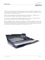
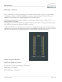
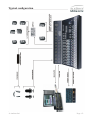
Owner’s Manual
Audient Limited, Aspect House, Hampshire,
England, RG25 2PN
Telephone: +44 (0) 1256 381944
www.audient.com
V 1.04
E&OE
Contents
Introduction
How to use this manual
Unpacking5
Service and Repair 6
Ventilation6
Power-up6
Audio interfaces
7
Dimensions7
Specifications8
Console layout
10
In-line architecture 11
Solo13
Metering13
Typical configuration
4
Overview
15
Glossary16
Console functions.
INPUT POD20
ROUTING AND AUXILIARIES 21
EQUALISER22
SHORT FADER (SF)
23
FLIP AND PAN
24
LONG FADER (LF)
25
INPUT CONNECTORS 26
STUDIO SPEAKERS AND FOLDBACK
27
CONTROL ROOM MONITORING
28
OSCILLATOR 29
SOLO29
COMPRESSOR30
STEREO INPUTS 31
LINE I/PS 17-14 AND SUB-GRP OUTPUTS. 32
TALKBACK33
AUX MASTERS
34
BUS MASTER TRIM
35
MASTER FADER 36
CONTROL ROOM CONNECTORS 37
STUDIO/ FOLDBACK CONNECTORS 38
AUX CONNECTORS
39
SUB-GRP INSERT/17-24 CONNECTORS
40
STEREO INPUT CONNECTORS
41
MONITOR INPUTS42
MIX OUTPUTS
43
BUS, SUB-GROUP/LINE 17-24 OUTPUT CONNECTORS
MASTER METERS45
SUB-GROUP/LINE INPUT 17/24 METERS
46
BLOCK DIAGRAMS
WARRANTY.51
47
44
Introduction.
Thank you for selecting this Audient product.
We hope that your new ASP4816 console will provide an intuitive, ergonomic and tactile path to analogue enlightenment.
ASP4816 is a small format analogue console with a big heart. Small in stature, yet not in functionality,
it provides an impressive array of connectivity, signal conditioning, routing, summing, processing and
monitoring capability in one beautiful, tidy package.
ASP4816 will adapt to become the centre of your creative workflow, equally suited to the project studio or high-end professional environment.
Lets take a look!
How to use this manual.
This manual has been divided into sections for your convenience.
The first section introduces ASP4816 and provides an overview of the control surface and where to
find things. The following sections provide detailed information regarding each function, operation of
controls and how they relate to each other. Along the way a number of handy tips and suggestions will
offer up possible uses and applications for the console during creative use.
© Audient Ltd
Page -4-
Introduction.
Unpacking
Your Audient ASP4816 Console has been carefully and meticulously tested and inspected before dispatch.
Please check for any signs of transit damage. If any signs of mishandling are found please notify the
carrier and inform your dealer immediately. The packaging should include the console, an IEC power
cord and this manual.
IMPORTANT SAFETY INSTRUCTIONS
Please read all of these instructions and save them for later reference before connecting ASP4816 to
the mains and powering up the console. To prevent electrical shock and fire hazard follow all warnings
and instructions marked on the ASP4816.
This unit is connected via its IEC power cord to the mains safety earth.
NEVER OPERATE THIS CONSOLE WITH THIS EARTH CONNECTION REMOVED.
Internal Switch Mode Power Supply & Mains Fuse
ASP4816 utilises an internal switch-mode power supply that is very quiet and passively cooled with
plenty of current capability and headroom. This switch-mode design will accept any A.C line voltage
from 90V to 264V. Please ensure your A.C mains line voltage is within this specification. Consult a
qualified technician if you suspect difficulties.
DO NOT ATTEMPT TO TAMPER WITH THE POWER SUPPLY OR MAINS VOLTAGES
- HAZARDOUS TO HEALTH.
Always replace the mains fuse with the correct value - T2A slow blow.
© Audient Ltd
Page -5-
Introduction.
Service and Repair
The console uses a complex internal pcb sandwich arrangement making field service only possible by
a qualified technician. If any technical issues do arise with your console, please contact your dealer as
soon as possible to arrange for technical support. Do not attempt to fix the console unless qualified to
do so. See the warranty section provided at the end of this manual for details of your cover.
However, if you do need to access the inside of the console, the mechanical design allows for easy
entry. If you do need to access the inside of the console for any reason please power down the device
and disconnect the IEC power cord before proceeding.
All audio path PCBs are panel mounted to the control surface, with the I/O connector PCBs mounted
to the rear of the chassis base. The switch mode power supply, and power distribution PCB are mounted to the chassis base. PCBs are linked via ribbon cables or small cable runs. As such the console can
be opened without stress or strain on internal wiring or components.
4 x M6 bolts located underneath the armrest allow this to be lifted off. The control surface module is
also held in place with 4 M6 bolts located on the underside of the chassis. Once these are removed the
control surface module can be hinged up using the hand hold cut-outs in the front surfce of the module. (just like a car bonnet!). A 45cm long prop is recommended to support the control-surface module,
freeing both hands for whatever issue you may be attempting to solve!
Ventilation
Care should be taken not to obstruct the series of ventilation holes in the metalwork of the console.
The desk is designed to release heat and take adequate air flow via these holes to ensure longevity of
performance. These are located underneath the armrest, in the sides of the console and meterbridge.
If mounting the console into some form of studio furniture or desk, please ensure a sufficient air gap at
these locations.
Lexan overlay
The front panel of the ASP4816 features a rugged under-surface printed polycarbonate overlay. Exposure to direct sunlight for extended periods of time should be avoided as this can have a detrimental
effect on the overlay panel and the control knobs. However at least the panel legending will not wear
off like some of the silk screened or engraved products of yesteryear!
Power-up
On power up, please check that the power rail indicators for +48v d.c
and +/-18v d.c light on the right hand side of the console.
© Audient Ltd
Page -6-
Introduction.
Audio interfaces
The ASP4816 has been designed and developed to provide highly robust system integration interfaces,
allowing worry-free system hook-up under the most demanding situations.
Inputs and outputs are implemented using advanced electronically balanced or ground sensing topologies and are fitted with extensive RFI rejection networks. All signal interfaces are also fully protected
against accidental misuse e.g. by the connection of phantom powered cables.
Pin conventions
Signal interfaces are provided on either metal shell locking XLR, TRS Jack or 25 pin D Sub connectors. XLR Pin 1 is connected to the chassis safety ground. XLR Pin 2 is designated as signal positive
and Pin 3 as signal negative.
To unbalance the outputs of the ASP4816 Pin 3 should be connected to Pin 1 at the output of the console. Similarly, inputs from unbalanced sources should be connected via twin screened cables with the
Pin 3 connection tied to the screen at the unbalanced source.
Screen connections
In order to maintain optimum EMC performance it is important that screens are properly connected at
both ends of cable runs. In this way the electromagnetic shield provided by the equipment chassis and
the cable screens will be optimised to reject interference.
It is recommended that only high quality braided screen cables are used to avoid compromising EMC
performance.
Dimensions
© Audient Ltd
Page -7-
Specifications
Frequency Response
Mic input to Mix output
Line input to Mix output
<+0,-0.3dB
<+0,-0.3dB
20Hz-20kHz @6-40dB gain.
20Hz-20kHz @0dB gain.
THD AND NOISE AT +20dB OUTPUT
Mic XLR input to any output
Line input to any output
Tape input to any output <0.005% at 1kHz
<0.005% at 1kHz
< 0.003% at 1kHz
NOISE
Mic EIN (20-20kHz, 150R source) <-127.5dBu
Bus noise (no inputs routed)
<-93dBu
Bus noise (36 inputs routed)
<-78dBu
CROSSTALK AND MUTE ATTENUATION AT 1kHz
Short fader Mute
>90dB
Long fader Mute
>90dB
Mix assign>90dB
Bus assign>90dB
MIC CMRR
70dB (Min gain)
75dB (Max gain)
MAXIMUM INPUT
Mic>+21dBu (min gain)
Line+30dBu (min gain)
insert return>+21dBu
MAXIMUM OUTPUT INTO 2K OHMS
Mix output>+26dBu
Bus output>+26dBu
Aux output>+26dBu
Insert send>+20dBu
Monitor, Studio, F/B outputs
>+20dBu
© Audient Ltd
Page -8-
Overview
ASP4816’s many features include 16 channels of Class-A discrete microphone preamplifiers as used
in our world renowned ASP8024 console and ASP008 8-channel microphone preamplifier, guaranteeing outstanding sonic transparency and detail.
When combined with high resolution bargraph metering, input conditioning, comprehensive cue
monitoring options, ASP4816 is right at home in a tracking environment.
A rear panel full of high quality locking XLR and TRS connectors ensures it is simple and quick to
integrate your favourite outboard and existing microphone preamplifiers.
However, ASP4816 is equally comfortable as a mixing tool - with up to 6 selectable aux sends, inserts
and dedicated DAW returns, 8 sub-groups with switchable inserts, 16 main output buses, classic Audient summing, VCA bus compressor and a high quality centre section complete with mono, dim, phase
and comprehensive monitoring configurations - any eventuality is covered.
© Audient Ltd
Page -9-
Overview
Console layout
© Audient Ltd
Page -10-
Overview
In-line architecture
ASP4816 has an In-line architecture. This means that the ‘channel path’ and the ‘monitor path’ are both
included in the same physical strip.
Because the two signal paths are integrated in this way, in-line consoles have sometimes been seen as
confusing. However great care has been taken in the cosmetic and ergonomic design of the ASP4816
to make the two paths easily distinguishable from one another. Dark areas of the control surface and
dark switch buttons are associated with the short fader (SF) or channel path while lighter areas of the
control surface are associated with the long fader (LF) or monitoring path.
For the remainder of this manual the signal paths will be referred to as the LF and the SF paths. As a
default condition the Mic/Line input feeds the SF path while the DAW return signal uses the LF path.
This assignnment can be reversed using the FLIP switch. To identify which mode
has been selected back lit legends indicate the signal source for each path.
Path swapping
As just discussed, the ASP4816’s In-Line architecture provides huge operational flexibility and power.
The block diagram on the next page shows the SF and LF (short and long fader) paths. The FLIP
switch is at the input of both paths and determines whether the MIC/LINE or the DAW input is used
for a particular path. The normal position for all switches on the console is UP and with the FLIP
switch in this position the DAW signal is routed through the LF path as shown.
By studying the diagram it can be seen that the MIC/LINE input is routed through the SF path but that
when the FLIP switch is pressed this situation is reversed and the DAW signal is now routed through
the SF path.
There are switches labelled SF associated with both the HF/LF equaliser and the MID equaliser. Again
the normal position of these switches is UP, placing the equalisers in the LF path. By pressing the SF
switches the equaliser sections can be moved over to the SF path. Thus it is possible to have the entire
equaliser in either the LF or SF path or one section of the equaliser in each path. This situation could
be useful when both the LF and SF paths are used for mixdown. If recordings are to be made with
equalisation then the equalisers should be placed in the SF path.
Note in this situation that you will hear the effect of the equalisation and it will be recorded. When the
equaliser is in the LF path you will hear the changes but they will not be recorded. They will only be
recorded if a stereo recording is made, as will be the case when mixing the title.
It is possible to source the auxiliaries from the SF path by pressing the SF switch associated with each
pair of auxiliaries. The auxiliaries can further be selected to be either pre or post fader for whichever
path they are in.
© Audient Ltd
Page -11-
Overview
© Audient Ltd
Page -12-
Overview
Solo
Pressing a solo button on a channel with either PFL or AFL selected allows either the PFL or AFL signal for that channel to be heard on the monitors and viewed on the stereo output meters.
Associated with the solo switch is the SOLO-IN-FRONT control and this allows the relative level of
the solo’d signal and the stereo mix to be adjusted. It is therefore possible to hear a channel in isolation
or with some amount of the mix behind it. Solo-in-Place is an extension of the AFL and PFL facilities.
If SIP is selected on the master module the signal on the main stereo bus will be replaced by the AFL
(Post Pan) signal of the solo’d channel. This is the equivalent of cutting all other channels except the
one you want to check, but is achieved by just a single button push.
Note that if you are recording when Solo in Place is used this will be recorded !
For this reason the SIP switch is illuminated alerting users to possible danger. The most likely use for
SIP will be just before a mix when equalisation is being set up. It is often easier to adjust the equalisation on a solo’d channel but it is essential to check how it sounds when in the mix.
Metering
Metering is extremely important as it can determine whether or not a signal is too low in level, in
which case it may be noisy, or too high in level in which case it may suffer distortion. The aim of the
meters is to assist in setting the signal level between the two extremes of noise and distortion.
A signal level that is too high clips meaning that the smooth waveform abruptly changes when the
electronics runs out of headroom. Normally a visual indication of impending clipping is given before
the audible effects become apparent.
At the other extreme, if there is insufficient signal, any noise present will be amplified along with the
signal when it is eventually brought up to the correct level. There are no indicators warning you of this
condition - only the fact that the signal is not “peaking” to any extent on the meter.
To aid this situation the ASP4816 has input and output meters. DAW input levels can be monitored on
a 20 segment meter, while microphone input levels can be monitored on a 3 segment meter. Provision
is made for the function of these meters to be reversed, as, particularly when tracking, it may be desirable to observe the input signal on the large meter.
© Audient Ltd
Page -13-
Overview
Metering - continued
0VU is calibrated to a nominal operating level of +4dBu. Which in turn is relative to a typical EBU
calibration of +18dBu = 0 dBFS. 0 dBFS is your absolute maximum digital level (full scale) and
should be avoided at all costs - digital clipping is not a pleasant sound.
As such the bargraph meter scale on ASP4816 is calibrated in dBFS, such that +4 dBu = 0VU = -14
dBFS. Therefore, a nominal
operating level of 0VU will result in 14 dB of headroom in your digital recording platform (providing
your AD/DA converters are aligned to 0 dBFS = +18 dBu.
14 dB of headroom is very useful as most music sources (except for the huge dynamic range of an orchestra) have crest factors (the difference between average (RMS) and peak level) of around 12-20 dB.
ASP4816 therefore provides ample headroom for your beautifully crisp transient sources.
Meters are provided for :Main Stereo Output (30 segment)
Line Inputs 17-24/Sub-group Outputs (20 segment)
DAW Inputs (20 segment)
MIC/LINE Inputs (3 segments)
© Audient Ltd
Page -14-
Typical configuration
© Audient Ltd
Page -15-
Glossary
AFL
This allows after fade (post fade) signals to be heard on the monitors and viewed on the main stereo
meters.
Auxiliaries
Sometimes known as auxiliary sends these are used as secondary mix buses. The mixes created on
these buses are then used to feed effect units or are fed back to the performers as a Foldback feed.
Every channel has access to the auxiliary mixes and the contribution of any channel can be varied by
using the appropriate auxiliary level control. Auxiliaries can be switched pre or post fader and be allocated to either the SF or LF signal paths.
Auxiliary Master
Associated with every auxiliary there is an auxiliary master control to give overall level control rather
than having to adjust the contribution from every channel.
Bus Master
Inputs are assigned to bus outputs through a routing matrix, enabling one or many inputs to be assigned to the same bus. The bus outputs usually correspond to inputs on the DAW or other recording
device. Each bus then has a mixing amplifier whose gain can be controlled by the Bus Master Trim.
This allows the level to a multi-track input to be raised or lowered without having to adjust the individual level of each channel routed to that track. The faders can still be used to adjust the relative levels of
channels.
Cut
The cut or mute control is used to silence (mute) a signal path when it is not in use. This removes the
noise contribution from that source leading to a quieter mix. There are cut switches in both the SF and
LF signal paths.
Dim
This allows the control room loudspeaker levels to be reduced by a preset amount. Dim will be brought
into action automatically when talkback is used preventing howl round.
Equaliser
Equalisers are what would be referred to as tone controls on consumer equipment. Equalisers are
divided into a number of bands - 4 in this case. There is scope to adjust high and low frequencies and
two bands of middle (mid) frequencies. The high and low frequency sections are shelving and the
turnover frequency is switchable. The middle frequency sections are peaking and the frequency of the
peak (or dip) is adjustable. It is also possible to alter the Q of the mid sections with a pot, making the
Q continuously variable between two values. In-line consoles often have the facility for the equaliser
to be split such that it can be used partly in the channel path and partly in the monitor path. The SF
switches on ASP4816 equalisers allow the HF/LF and MID equalisers to be independently switched
into the SF signal path.
© Audient Ltd
Page -16-
Glossary
Flip
Flip allows the inputs to the signal paths to be swapped. Normally the LF path will carry the DAW
input, however, with FLIP pressed it will carry the MIC/LINE input while the DAW input will travel
through the SF path.
Foldback
Foldback is a mix that is returned to the performers in the studio in order that they can play in time
with what is already recorded. It could simply be the console stereo output although more usually it
is taken from a pair of auxiliary buses allowing a different mix to be created. Talkback may also be
included on the foldback outputs enabling communication with the artists.
In-line
This refers to a type of console which contains two signal paths within a channel stip. The channel
signal path is used to feed a DAW or other recording device while the monitor path is used to carry
the output of the DAW (or other recording device) through to the stereo mix bus. In-line consoles can
be more compact than split consoles or can carry more channels for a given size. The possibility of
switching signals between the two paths and of sharing facilities between the paths makes the in-line
concept a very attractive one.
Insert points
Insert points allow the signal path to be broken allowing the insertion of some signal processing device. The device inserted is then in series with the signal path. When not required the device can either
be switched out using the INSERT switch or unplugged from the console.
LF
The Long fader is normally used to feed the mix. The lighter areas of the channel strips are areas used
for the LF signal path. There may be a dark switch labelled SF allowing that facility to be switched
into the SF or short fader path.
Line
The line input is a high level, high input impedance input intended for high level sources such as the
outputs of a DAW or other recording device, sampler etc.
Mic
The microhone input is a low level, low impedance input intended for use by low output devices such
as microphones. This contrasts with the line input which is intended for use by equipment with high
output levels, such as a DAW line output for example.
Mix
This allows signal to be routed to the stereo mix bus which is the main output of the console. This routing can be applied to both the SF and LF signal paths and is particularly useful during mix down when
as many inputs as possible are often required.
© Audient Ltd
Page -17-
Glossary
Pan
Short for panoramic potentiometer this control places a mono source signal onto the stereo bus. The
proportion of signal fed to the left and right buses is variable (using the pan control) and alters the spatial position of an instrument within the mix. Thus a number of channels can all be panned to different
spatial positions. Generally low frequency instruments such as kick drums are panned centrally as they
are omnidirectional and for a given SPL the speakers are being driven at a lower level leading to less
distortion. Signals can also be panned across odd and even bus outputs allowing them to recorded in
stereo.
Q
Q is an indication of the frequency range or bandwidth over which a peaking equaliser will be effective. Low Qs affect a wide range of frequencies while high Qs affect a much narrower range of frequencies. It thus allows an equalisation adjustment to be targeted to maximise the effect where required while at the same time minimising changes where they are not wanted. Generally high Qs sound
less pleasant than low Qs.
Routing
This is the process of selecting to which bus output of the console the signal should be routed. Routing
can be to multiple tracks and if an odd/even combination is selected then panning can be used to record
a stereo signal.
SF
The Short fader is normally used to feed the inputs to a DAW or other recording device. It therefore
controls the recorded level of the signal. When SF appears by a control or group of controls it means
that these functions can be switched into the short fader (or channel fader) path.
Shift
This allows the number of routing switches to be reduced by doubling the function of each switch.
With Shift unpressed routing is possible to tracks 1 through 8. With Shift pressed routing to tracks 9
through 16 is possible.
Solo in place
This is a method of previewing the signal in a channel and works by cutting all the signals feeding the
stereo bus other than the one(s) being solo’d. This is a destructive process and does affect the stereo or
mix output of the console.
Stereo Bus
This is usually the main bus in the console and provides the output to whatever stereo recording device
is in use. The stereo output is also used as the main monitor source allowing the output of the multitrack to be heard and the balance of the individual tracks in the mix to be adjusted.
Talkback
Talkback is a means of communication from the mixing console to the performer.
© Audient Ltd
Page -18-
Console functions.
© Audient Ltd
Page -19-
Console functions.
CHANNEL STRIP
INPUT POD
The input pod is the gateway to
the remainder of the signal processing of the console. There are
three inputs, a mutually exclusive
microphone and line input, and a
tape input.
Note the different colouring used
to identify the different signal
paths of the pod. Anything on a
light background is associated
with the LF path while anything
on a dark background is associated with the SF path.
The mic/line input normally sends
signal to the SF or short fader signal path of the console while the
DAW input normally sends signal
through the LF or long fader
path of the console unless this is
reversed by the FLIP switch.
There are two meters associated
with the inputs, a 20 segment
0dBFS peak reading meter showing the DAW input signal and a 3
segment peak reading meter gives
an indication of the mic/line level.
1 20 Segment meter (normally
monitoring the DAW input)
7 INSERT IN - places an insert
point in the MIC/LINE path.
2 3 Segment meter (normally
monitoring the Mic/Line
input).
8 Mic/Line GAIN Control
3 INSERT IN places an insert
point in the DAW path
4 DAW Input TRIM control
5 MIC/LINE switch - press
down to select the line input.
6 MTR - press to show the mic/
line input on the large meter
and the DAW input on the
small meter.
© Audient Ltd
9 O Polarity (Phase) Reverse
Switch
10 48V Phantom Power Switch.
Turn the loudspeakers down
before switching this on or
off!
11 High Pass Filter Switch. A
high pass filter can be used
to get rid of any unwanted
low frequencies that may be
present such as air conditioning
rumble.
Both the MIC/LINE and the DAW
inputs have insert points which
can be switched in and out of
circuit.
The Mic Input has a gain control
range of +6dB to +60dB and the
Line Input has a range of -14dB
to +40dB. Switches allow for
Phantom Power, Polarity Reversal
and High Pass filtering - enabling
rumble and sources alignment issues to be easily dealt with.
The DAW input has a trim control
with a range of ±15dB.
There is a back illuminated number at the bottom of the pod for
channel identification.
Page -20-
Console functions.
CHANNEL STRIP
ROUTING and
AUXILIARIES
The routing section takes the signal
from the SF path and routes it to
the bus outputs which in turn are
usually connected to the inputs of
a DAW or other recording device.
Buses 1 to 8 also have a parallel
path and feed the 8 sub-groups.
These can be used to pre mix
channels together for final mix
down or as sends to a DAW or
other recording device.
There are 16 bus outputs accessed
by 8 routing buttons and a SHIFT
button.
Routing can be to multiple outputs
and if odd and even outputs are
selected panning can be used to
place the signal within a stereo
image.
With mulitple buses available it
is possible to achieve a variation
on the multi-bus compression
techniques made popular by mix
engineers like Michael Brauer.
(See www.mbrauer.com/articles).
1
ROUTING SWITCHES
select the bus outputs that the
SF signal is sent to. The first
eight switches also route to the
8 sub-groups
2 SHIFT gives access to bus
outputs 9-16.
3 PAN allows the signal to be
panned across odd and even
buses.
4 LF replaces the SF signal
being sent to the routing
switches with the signal from
the LF signal path.
© Audient Ltd
5 LEVEL adjusts the level sent
to an auxiliary output.
6 SF allows the signal feeding
the auxiliary to be taken from
the SF signal path.
7 PRE allows the auxiliary
signal to be taken pre fader
instead of the normal situation
where it is taken post fader.
8 CUE A and B are identical in
operation to the others but can
be individually switched into
the SF path.
The LF switch moves the routing
from the SF path over to the LF
path and can be useful for track
bouncing. If PAN is down and
routing is again selected for odd
and even buses then the post fade
post pan LF signal is sent to the
bus outputs selected.
There are 8 auxiliary outputs. The
Auxiliaries can be switched to the
SF path.
Cue A and B work in the same
manner as the other auxiliaries
but are intended mainly for use
as sends to the FOLDBACK
system.
Page -21-
Console functions.
CHANNEL STRIP
EQUALISER
Note the dark background indicating
that the equaliser is normally
associated with the LF signal path.
The equaliser is split into two
sections - one for high and low
frequencies (HF/LF) and the other
for middle frequencies (MIDS).
Both sections can be switched in and
out independently and switched into
the SF signal path independently.
The HF section has a boost/cut
range of 15dB. The frequency
can be switched - 10kHz with the
switch up and 18kHz with the switch
depressed.
The LF section has a boost/cut
range of 15dB and a shelving
characteristic. The frequency can
be switched - 50Hz with the switch
up and 100Hz with the switch
depressed.
1 HF/LF Section. This places the
HF/LF equaliser in circuit.
2 SF places the HF/LF equaliser
in the SF signal path where it
can be used to treat a signal
before it is recorded.
3 10kHz/18kHz allows the
frequency of the HF equaliser
to be selected.
8 SF places the MIDS equaliser
in the SF signal path where it
can be used to treat a signal
before being recorded.
9 This controls the centre
FREQUENCY of the high
mid equaliser.
10 H I G H M I D b o o s t / c u t
control.
4 HF boost/cut control.
11 HIGH MID Q control.
5 50Hz/100Hz allows the
frequency of the LF equaliser
to be selected.
12 This controls the centre
FREQUENCY of the low
mid equaliser.
6 LF boost/cut control.
13 LOW MID boost/cut control.
7
14 LOW MID Q control.
MIDS Section. This places the
MIDS equaliser in circuit.
© Audient Ltd
The high mid section (HMF) has
three controls. The boost/cut range is
15dB and the frequency of operation
can be varied from 450Hz to 20kHz.
A Q control allows for a very sharp
and narrow characteristic or for a
more gentle characteristic covering
a wider range of frequencies.
The low mid section (LMF) has
three controls. The boost/cut range is
15dB. and the frequency of operation
can be varied from 50Hz to 1.5kHz.
A Q control allows for a very sharp
and narrow characteristic or for a
more gentle characteristic covering
a wider range of frequencies.
The actual Q range is between 3.8
(0.4 Octave) and 0.65 (2 octaves).
Page -22-
Console functions.
CHANNEL STRIP
SHORT FADER (SF)
There are 3 back illuminated
indicators showing the selected
input to the SF path. This can be
changed between Mic/Line and
DAW using the FLIP switch.
LF Source allows the source for
the SF path to be taken from
the LF path. This could be used
during mixdown to send the LF
signal through the SF path up to
the routing matrix where the bus
outputs can be used as additional
effect sends. Normally this signal
is derived after the long fader
(POST LF) but it can be made PRE
LF by changing an internal link on
the circuit board.
1
SOURCE selects the post fade
LF signal as the input to the
SF signal path, over-riding the
MIC or DAW selection from
the Flip switch. By altering a
link on the circuit board this
signal can be made pre fade.
The LF legend will illuminate
when the switch is pressed and
the MIC/DAW indicator will
blank.
2 MIC/DAW. These back lit
indicators show whether the
MIC/LINE or the DAW input
is selected to the SF path. Only
one will be illuminated and it
can be changed by using the
FLIP switch.
3 This is the PAN control for
the SF signal enabling it to be
panned across odd and even
buses.
© Audient Ltd
4 MIX routes the SF signal
to the stereo mix bus. It is
good practice to unroute
any channels which are not
needed. This will reduce mix
amp noise.
5 This is the SHORT FADER
which controls the level of the
SF signal.
6 SOLO allows the SF signal to
be heard on the monitors and
viewed on the master meters.
If Solo In Place is selected
it will replace the console
output.
7 CUT allows the SF signal
path to be muted. This may
help to reduce noise in a mix
if a channel is not in use for a
period of time.
The source switching occurs before
the equaliser so it is possible
to equalise the SF signal which
has been taken from the LF path
by switching either one or both
equaliser sections into the SF path.
(If this is done then the equaliser
section is no longer available in
the LF path).
The SF PAN control allows
panning across the bus outputs
when pan is selected on the routing
section of the strip.
MIX allows the SF signal to be
routed to the stereo mix bus and
allows the SF path to be used as an
additional input during mixdown.
The short fader is designed for use
with 10dB of gain in hand allowing
the signal to be boosted or reduced
in level if required.
The SOLO switch allows the
channel to be auditioned through
the AFL/PFL or Solo in Place
facilities.
CUT allows the SF signal path to
be muted.
Page -23-
Console functions.
CHANNEL STRIP
FLIP and PAN
The FLIP switch allows the MIC/
LINE input and the DAW input to
be reversed. Normally the DAW
input feeds the LF signal path - with
FLIP pressed it will feed the SF
signal path. The MIC/LINE input
normally feeds the SF signal path
and with FLIP pressed it will feed
the LF signal path. Illuminated
indicators in each section show
which input is selected to the LF
and SF paths.
The PAN control pans the LF signal
across the stereo mix bus and the
MIX switch assigns the LF signal
to the stereo bus.
The SOLO switch allows the
long fader signal to be auditioned
through the AFL/PFL or Solo in
Place facilities.
1 FLIP swaps the inputs between
the LF and SF paths.
2 These back lit indicators
show whether the MIC/LINE
or the DAW input is selected
to the LF path. Only one will
be illuminated and it can be
changed by using the FLIP
switch.
3 MIX allows the LF signal to be
routed to the stereo mix bus.
Normally this switch should be
pressed but it is good practice
to unroute any channels which
are not needed. this will help
to reduce mix amp noise.
5 SOLO allows the LF signal to
be heard on the monitors and
viewed on the master meters
or, if Solo in Place is selected,
it will replace the console
output.
CUT allows the LF signal path to
be muted.
Page 33 gives more detail regarding
the long fader used to control the
level of the LF signal path.
6 CUT allows the LF signal path
to be muted. This may help to
reduce the noise in a mix when
a channel is not in use for a
period of time.
4 This is the PAN control for
the LF signal enabling it to be
panned across the stereo bus
© Audient Ltd
Page -24-
Console functions.
CHANNEL STRIP
LONG FADER (LF)
Located close to the operator this
fader operates on the LF signal
path and is therefore mainly used
for creating the monitor mix and
the final stereo mix for the title.
The fader is expected to operate
around the 0dB mark with 10dB
of gain in hand allowing the signal
to be increased or decreased in
level.
When level setting start with the
fader in this position then adjust
the input sensitivity control for the
correct level to optimise the gain
structure.
1 This is the LONG FADER
which controls the level of the
LF signal.
3 This is the 0dB mark. This is
the normal operation position
for the fader.
2 This is the +10dB mark. The
fader is fully open at this point
and introducing 10dB of gain
into the signal path.
4 With the fader here the signal
path is closed and no signal
will pass.
© Audient Ltd
Page -25-
Console functions.
CHANNEL STRIP
INPUT CONNECTORS
The rear mounted connector panel
is where the input, output and insert
point connectors are located.
The microphone input uses an XLR
connector while the line input, DAW
input and the insert sends and returns
use Tip, Ring and Sleeve jacks.
1 MICROPHONE INPUT.
Microphones or other low
levels inputs can be connected
to this input.
2 LINE INPUT. This input can
be selected in place of the
microphone input. Like the
DAW input it is suitable for
high level line sources.
3 MIC/LINE INSERT SEND .
This is the insert point send
output for the microphone and
line input. Signal is always
present here and can be used
as an additional output. Only
the Mic/Line signal will appear
here and it is not affected by
the Flip switch.
4
5 DAW INPUT. The output of
the DAW should be connected
here although the input is
suitable for any high level line
source.
6 DAW INSERT SEND. This
is the insert point send output
for the DAW input. Signal is
always present here and this
can be used as an additional
output. Only the DAW signal
will appear here and it is not
affected by the Flip switch.
7 DAW INSERT RETURN.
When the insert point is in use
the signal from the external
processing equipment should
be connected here.
MIC/LINE INSERT RETURN.
When the insert point is in use
the signal from the external
processing equipment should
be connected here.
© Audient Ltd
Page -26-
Console functions.
MASTERS
STUDIO SPEAKERS and
FOLDBACK
This section of the master
module looks after the
STUDIO LOUDSPEAKER
and FOLDBACK outputs of the
console. In every case the same
sources are available EXT 1
EXT 2
CONTROL ROOM (C/RM)
AUXILIARY A (AUX A)
AUXILIARY B (AUX B)
EXT 1 and 2 are external inputs to
the console and could be anything
you care to plug in.
C/RM selects the control room
monitor output as the source. This
is used to provide a playback of
the MIX to the studio speakers,
or to set up a quick foldback mix,
perhaps with a little help from the
Aux A and Aux B buses.
1 SOURCE SELECT. These
select the signals to be sent to
the studio loudspeakers and
foldback.
4 FOLDBACK 1 SOLO switch.
Allows foldback 1 to be
checked on the control room
monitoring system.
2 The LEVEL controls set the
Studio Loudspeaker and
Foldback levels.
5 FOLDBACK 2 SOLO switch.
Allows foldback 2 to be
checked on the control room
monitoring system.
3 Studio Loudspeaker ON
switch. This activates the
Studio Loudspeaker.
© Audient Ltd
CUE A and CUE B are mono
sources which can be independently
selected to the left and right sides
of the studio speaker or foldback
outputs.
Each output has a level control.
The studio loudspeaker has a
ON switch and the FOLDBACK
outputs have SOLO switches.
These enable the foldback mix to
be created or checked in the control
room. This is always AFL.
Page -27-
Console functions.
MASTERS
CONTROL ROOM
MONITORING
The Control Room Monitoring
system is one of the most used
systems in a studio. Typically there
are several sets of loudspeakers
with a main pair and one or
more alternate pairs. These are
sometimes referred to as Near, Far
and Mid field monitors depending
on their proximity to the listening
position.
The ASP4816 provides for 4 pairs
of loudspeakers, a MAIN pair and
ALTERNATE 1, 2 and 3. Source
selection is made from either the
MIX or DAW, EXT 1 and 2.
Each loudspeaker pair has its own
level control. The control for the
main pair is larger than the controls
for the alternate monitors. The
level controls are independent of
each other.
Associated with the main
loudspeakers are some further
controls allowing the left and
right outputs to be independently
or simultaneously CUT, the
monitoring system to be placed in
MONO mode, or for the output to
be dimmed by a preset amount.
1 SOURCE SELECT buttons.
2 LEVEL controls for the
alternate loudspeakers.
3 SPEAKER SELECT buttons.
4 Main Loudspeaker LEVEL
Control.
5 MONO button allowing the
signal to be checked for mono
compatibility.
© Audient Ltd
6 C U T b u t t o n s a l l o w i n g
independent cutting of the
left and right speakers.
7 DIM allows the speakers to
be reduced in level by a preset
amount (15dB).
8
CUT allows the speakers to be
completely silenced.
Page -28-
Console functions.
MASTERS
OSCILLATOR
The 4 frequency oscillator can be
assigned either to buses 1-16 or
to the stereo mix bus. The level
is adjustable and when not in use
the oscillator should be completely
turned off.
SOLO
This is the master control area
for the AFL/PFL and SOLO IN
PLACE system. If SIP is not
illuminated then the console will
be in either AFL or PFL mode
depending upon the PFL/AFL
switch.
PFL allows pre fade signals to be
auditioned on the monitors and
viewed on the master meters by
pressing the SOLO button on the
appropriate channel strip.
1 Oscillator FREQUENCY
selection switches. Frequencies
of 40Hz, 1kHz, 10kHz or
15kHz can be selected using
the two switches.
2 O s c i l l a t o r R O U T I N G
switches. These route the
oscillator signal directly to
either the buses 1-16 or the
stereo mix bus.
3 Oscillator LEVEL Control.
4 O s c i l l a t o r O N s w i t c h .
During normal operation of
the console ensure that the
oscillator is switched OFF.
5 SOLO level control.
© Audient Ltd
6 SOLO IN FRONT alters the
ratio of the SOLO signal to the
MIX signal making it possible
to listen to the SOLO’d signal
in isolation or combined with
some amount of the stereo
mix.
7 The SIP switch switches the
console into SOLO IN PLACE
mode. This means that the solo
signal will replace the mix
signal at the stereo output of
the console.
8 This selects either PFL or
AFL mode. This switch is not
effective in SOLO IN PLACE
mode.
AFL allows the post fade post
pan signals to be auditioned on
the monitors and viewed on the
master meters by pressing the
SOLO button on the appropriate
channel strip.
A control adjusts the relative level
of the solo signal and the mix
signal allowing the solo’d channel
to be heard in isolation or with
some amount of the mix.
SIP mode allows the post pan signal
to be auditioned by switching the
solo’d channels onto the console
output and muting the stereo mix
for the duration of the solo. Since
this happens on the mix output,
solo in place should not be used
during mixing but is very helpful
when setting up the mix.
Page -29-
Console functions.
MASTERS
COMPRESSOR
A compressor can be switched into
the main stereo signal path when
required. Note that it is located after the mix insert point but before
the main fader.
The compressor characteristics are
optimised for use in mix processing
while many of the parameters remain
under the control of the engineer.
Threshold, Gain Make Up, Attack,
Release and Ratio are all adjustable
while the entire processor can be
switched out of circuit when not
required.
A bargraph meter indicates the
amount of compression applied to
the signal. When compression is
taking place this should show some
very healthy activity. Please do not
try to over compress the mix output
as the results will sound terrible.
Always use your ears to check the
effect that you are trying for!
1 A 12 segment bargraph
METER indicating the
amount of gain reduction
taking place.
2 THRESHOLD control for
determining the level where
compression starts. Threshold
can be set between -20dBu
and +20dBu.
3 ATTACK controls the speed
with which the compressor
reacts. Attack is adjustable in
6 steps from 0.1 to 30ms.
4
RATIO determines the amount
of compression used once the
signal is above the threshold
level. For example a ratio of
2:1 means that the output will
rise 1dB for every 2dB rise in
input level.
© Audient
Ltd
Ratios of 4:1 and 10:1 are also
available.
5 MAKEUP is a gain control.
When a signal is compressed
the level is reduced. A gain
make up stage restores the
peak level although of course
the dynamic range of the
signal has now been reduced.
40dB of gain is available.
A good use of the compressor may
be to limit peak signals by setting a
highish threshold with a high ratio.
Thus when the threshold is reached
the signal is barely allowed to
increase beyond it.
6 RELEASE controls the speed
at which the compressor
allows the gain to return to
normal when the signal drops
below the threshold level.
Release is available from
0.1s to 2.4s in 5 steps with an
additional AUTO setting.
7 The IN switch puts the
compressor into circuit.
Page -30-
Console functions.
MASTERS
STEREO INPUTS
1 ROUTING SWITCHES
allowing the input signal to
be sent to the DAW or other
recording device.
2 SHIFT button working with
the routing switches to give
access to tracks 9-16.
3 F/B A allows the input signal
to be fed to Foldback A.
4 F/B B allows the input signal
to be fed to Foldback B.
5 TRIM control to compensate
for different input levels. This
has a range of ±20dB.
6 Rotary FADER allowing the
input signal to be faded up or
down as required.
7
MIX allows the input signal to
be sent to the stereo mix bus.
8 SOLO allows the input signal
to be auditioned depending
upon the selected solo mode.
9
© Audient Ltd
The Stereo inputs allow signals to
be brought back into the console
(returned) from an effect unit
without using up a complete
channel strip. Often stereo signals
can only be routed to the stereo
mix, however, the ASP4816 stereo
inputs allow routing back to the
multi-track in addition to the mix.
This means that effects can be
recorded on the multi-track.
Routing to the foldback system is
also possible using F/B A and F/B
B allowing performers to hear any
reverberation or other effect.
A gain trim with 20 dB of range,
rotary fader, solo and cut switch
complete the facilities on the
input.
The stereo channels effectively
increase the number of inputs
on the console that are available
especially during a mix down.
CUT is used to mute the signal
or simply remove any noise
contribution from the return
Page -31-
Console functions.
MASTERS
LINE I/Ps 17-14 and
SUB-GRP OUTPUTS.
1 The PAN knob pans the subgroup signal across the stereo
bus.
2 MIX allows the sub-group
to be assigned to the stereo
mix bus and hence the main
console output.
3 SOLO allows the sub-group
signal to be auditioned
depending upon the selected
pan mode.
4 CUT mutes the sub-group
output.
In addition to routing signal to the
bus outputs for recording, the first
eight buses are also fed to 8 subgroup outputs. Each sub-group has
a PAN control, SOLO and CUT
switches and a fader controlling
the bus output level. The subgroups have insert points located
on the rear panel of the console
allowing external processing to
be patched in when called for. The
MIX switch assigns the sub-group
to the stereo mix bus and allows
the sub-groups to be used in mix
down.
T h e s u b - g r o u p I N S E RT
RETURNS are also used as Line
inputs 17-24.
LINE I/Ps 17-14 and
SUB-GRP FADERS.
1 The SUB-GROUP FADER
sets the level of the sub-group
output signal.
2 This is the +10db mark. The
fader is fully open at this point
and introducing 10dB of gain
into the signal path.
The 8 sub-group/Line input 17-24
faders are located in the centre of
the console, close to the operator,
and control the sub-group output
levels. These outputs are directly
available at the rear of the console
or they may be used to feed the
stereo mix bus simply by pressing
the mix buttons.
3 This is the 0dB mark which is
the normal operation position
for the fader.
4 With the fader here the signal
path is closed and no signal
will pass.
© Audient Ltd
Page -32-
Console functions.
MASTERS
TALKBACK
Talkback is used to communicate
with the STUDIO, the FOLDBACK
system or the Bus outputs of the
console. Note that the talkback
to the foldback system will work
even when the foldback levels
are turned down. The talkback
microphone may be phantom
powered by connecting Link 1 on
the PC10801 board.
1 The LEVEL control adjusts
the talkback level.
4 Pressing FB lets you talk to the
Foldback outputs.
2 Pressing SLATE allows
talkback to the bus outputs.
This allows track identification
information, for example, to
be recorded.
3 Pressing SLS lets you talk to
the studio loudspeaker.
© Audient Ltd
In all cases pressing a talkback
key will cause the control
room monitors to dim. This
helps prevent feedback, makes
the talkback more intelligible
and does not affect the console
outputs.
Page -33-
Console functions.
MASTERS
AUX MASTERS
1 A U X I L I A RY M A S T E R
LEVEL controls the overall
auxiliary output.
2
SOLO button used to audition
the auxiliary output. This is
always AFL.
3
The LINK button is used when
it is required to combine signals
from different auxiliaries into
a common signal. The leftmost
auxiliary becomes the overall
master, thus if auxiliary 3 is
linked to auxiliary 1 then the
output of auxiliary 1 should be
used as the master output.
The auxiliary masters control
the overall level of the auxiliary
outputs. A balance or mix can thus
be created by using the controls
on the channel strips and the
overall level adjusted by using
the auxiliary master control. The
auxiliary outputs can be solo’d so
that a balance can be created by
listening to the output.
A typical mixing situation may
require that the LF and SF paths
feed the same effect device.
Although an auxiliary send can
be assigned to either of the two
paths they naturally cannot access
both paths at the same time. By
linking auxiliaries this problem
is overcome and if the auxiliary
3 signals need to be combined
with those on Auxiliary 1 this
can be achieved by simply using
the link facility. The following
combinations are possible:
AUXs 3 and 5 can be linked to
AUX 1.
AUX s 4 and 6 can be linked to
AUX 2.
© Audient Ltd
Page -34-
Console functions.
MASTERS
BUS MASTER TRIM
1
© Audient Ltd
BUS MASTER TRIM controls
the overall level of a bus
output.
The BUS MASER TRIMS are the
final stage of level control over the
signals routed to the bus outputs.
Each bus output has a trim with a
range of ±10dB.
Page -35-
Console functions.
MASTERS
MASTER FADER
The master fader is used to control
the stereo output of the console.
Unlike the channel faders it is
calibrated with the 0dB mark at
the top as the main purpose of this
fader is to create a fade out at the
end of a title.
Under normal operating conditions
the fader should always be set at
maximum. If it has to be pulled
back a significant distance it
indicates that the levels to the mix
bus are too high and should be
reduced.
1 T h e M A S T E R FA D E R
controls the level of the stereo
output signal.
© Audient Ltd
2
This is the 0db mark. The fader
is fully open at this point.
3
With the fader here the signal
path is closed and no signal
will pass.
Page -36-
Console functions.
MASTERS
CONTROL ROOM
CONNECTORS
1 M A I N C o n t r o l r o o m
loudspeaker output.
2 ALTERNATIVE 1 loudspeaker
Output.
3 ALTERNATIVE 2 loudspeaker
Output.
4
© Audient Ltd
ALTERNATIVE 3 loudspeaker
These are the connectors for the
control room loudspeakers. There
is a main output and 3 alternative
outputs which can be selected from
the control surface of the console.
Each output is stereo, having a left
and right connector.
The console does not contain any
power amplification and these
outputs should be connected into
a suitable power amplifier for the
loudspeakers in use.
The speakers may of course be self
powered in which case connection
should be made to the inputs on the
loudspeakers.
Page -37-
Console functions.
MASTERS
1 STUDIO LOUDSPEAKER .
These carry the outputs to the
studio loudspeaker system.
The output depends upon the
selection made on the control
surface of the console.
2 F O L D B A C K A o u t p u t .
Foldback is normally used
as a feed to headphones. The
output depends upon the
selection made on the control
surface of the console.
© Audient Ltd
STUDIO/ FOLDBACK
CONNECTORS
3 F O L D B A C K B o u t p u t .
Foldback is normally used
as a feed to headphones. The
output depends upon the
selection made on the control
surface of the console.
These are the XLR connectors for
the Studio Loudspeaker and the
two foldback outputs. Each output
is stereo, having a left and right
connector.
The console does not contain any
power amplification and these
outputs should be connected into
a suitable power amplifier for
the loudspeakers or headphones
in use.
The speakers may of course be self
powered in which case connection
should be made to the inputs on the
loudspeakers.
Page -38-
Console functions.
MASTERS
AUX CONNECTORS
Not all of the ouputs are shown
for clarity.
1 CUE A and CUE B outputs.
These auxiliaries are normally
used as feeds to the foldback
system by selecting them
on the control surface of the
console. They can also be used
as additional effects sends.
2
© Audient Ltd
The auxiliary outputs are typically
used to send to effect units such as
reverberation units. They are line
level fully balanced outputs.
AUXILIARY 1 and 2 outputs.
The remaining auxiliary
outputs are identical.
Page -39-
Console functions.
MASTERS
SUB-GRP INSERT/
LINE INPUT 17-24
CONNECTORS
This panel carries the connectors
for the sub-group insert points.
There are 8 sub-groups and each
insert point has a send output and
a return input.
Signal is always present on the
send output. If required the insert
returns could be used as very basic
inputs to the stereo mix bus during
mixdown, from a submixer or
sampler etc.
The insert return jacks can also
be used to provide 8 additional
line inputs to the mix. These are
designated as Line inputs 17-24.
Note that the additional line inputs
are not available if the insert return
is also being used.
© Audient Ltd
Page -40-
Console functions.
MASTERS
STEREO INPUT
CONNECTORS
This panel carries the input TRS
jacks for the stereo inputs located
on the master section of the
console.
There are 4 returns each with a left
and a right input.
If a mono source is used then it
should be plugged into the left
input. This is normalled over to
the right input causing the signal
to travel through the left and right
signal paths of the return. If a plug
is inserted into the right input the
normalled connection is broken.
© Audient Ltd
Page -41-
Console functions.
MASTERS
MONITOR INPUTS
This panel carries the connectors
for the external inputs to the
monitoring system.
All three inputs are available
as sources to the control room
monitoring system while the first
two can be used as sources for the
studio monitoring system and the
foldback system.
1 Input for DAW
2 Input for EXT 1
3. Input for EXT 2.
© Audient Ltd
Page -42-
Console functions.
MASTERS
MIX OUTPUTS
There are 3 sets of stereo output
connectors enabling the connection
of 3 stereo recording machines.
The outputs can be used for many
purposes of course.
Associated with the outputs are
the mix insert points. They allow
a final mix processor to be inserted
into the MIX path, and are located
before the MIX compressor/
limiter.
1 MIX INSERT SEND jacks.
There is a separate send output
for the left and right mix.
2 MIX INSERT RETURN jacks.
There is a separate return input
for the left and right mix.
3
© Audient Ltd
MIX OUTPUT (Stereo Output)
connectors. There are three
sets of connectors which can
all be used simultaneously.
Page -43-
Console functions.
MASTERS
BUS, SUB-GROUP/
LINE 17-24 OUTPUT
CONNECTORS
Rather than having individual
connectors for each bus and subgroup output it is much more
convenient (and quicker to make
a connection) if they are on D-sub
multi-pole connectors.
1 SUB-GROUP/LINE 17-24
OUTPUT CONNECTOR
2 CONNECTOR for BUS
outputs 1 through 8.
The bus sends are split across 2
connectors with each carrying the
bus outputs for 8 tracks. The subgroup/line 17-24 outputs are on a
third connector.
3 CONNECTOR for BUS
outputs 9 through 16.
© Audient Ltd
Page -44-
Console functions.
MASTERS
THE MASTER
METERS
Metering has been addressed on
the input modules although there
are also meters associated with the
master functions on the console.
The output meters show the output
levels of the sub-groups and also
the stereo output. If problems
are indicated here with the level
being either too high or low then
it is most likely that the problem
is further back in the signal path.
Follow our procedure for gain
setting to see if this remedies the
situation.
1
Power Supply Status Indicators
for the +18V, -18V and 48V
power rails.
2 Left and Right Peak Reading
Main Output Meters.
3 O v e r I n d i c a t o r s , w h e n
illuminated the signal is in
danger of being clipped and
the level should be reduced.
A level of +20dBu will
bring the OVER indicator
on. Maximum or 0dBFS is
indicated at a signal level of
+18dBu, corresponding to
full modulation on a digital
recorder.
© Audient Ltd
4 0VU. When the signal is at a
level of +4dBu the bars should
be illuminated up to this point.
Note that this is not meant
to be normal operating level
because the meters are peak
reading.
5 Ta l k b a c k M i c r o p h o n e
Connector. If talkback is to
be used then a microphone
should be plugged in here.
6 Solo Indicator. This lights
when a SOLO button has been
pressed on the console.
Page -45-
Console functions.
MASTERS
THE Sub-group/
LINE INPUT 17-24
METERS
There 8 sub-group outputs meters
on the console (only 2 have been
shown for clarity). The sub-groups
are accessed in parallel with the
main bus outputs and only the
first 8 buses therefore have a
corresponding sub-group.
The sub-groups are able to feed the
stereo mix and also have their own
outputs located on the rear panel of
the console.
The sub-group outputs can be
directly used to feed a DAW or
other recording device.
The sub-group insert returns can
also be used to access line inputs
17-24, which share access to the
same routing and level controls as
the sub-groups themselves.
1 Sub-group Meter. There are
8 peak reading sub-group
meters - 1 for each sub-group
output.
2 O v e r I n d i c a t o r. W h e n
illuminated the signal is in
danger of being clipped and
the level should be reduced.
Like the main meters this
will illuminate with a signal
level of +20dBu. 0dBFS is
indicated at a level of +18dBu,
which normally corresponds
to full modulation on a digital
recorder.
A typical use for the sub-groups
would be during mixdown when
a number of signals are to be
combined to one fader for simpler
control. If the signals are on the
LF path then they must first of all
be sent to the routing matrix by
pressing the button in the routing
section. By routing the signals to
buses 1 through 8 they will also be
routed to the sub-groups.
3 0VU. When the signal is at
a level of +4dBu the bars
should be illuminated up to
this point. Note that this is not
meant to be normal operating
level because the meters are
peak reading.
© Audient Ltd
Page -46-
Block diagrams
© Audient Ltd
Page -47-
© Audient Ltd
Page -48-
© Audient Ltd
Page -49-
© Audient Ltd
Page -50-
Warranty.
Your ASP4816 comes with a manufacturer’s warranty for one year from the date of despatch to the end
user.
The warranty covers faults due to defective materials used in manufacture and faulty workmanship
only.
During this warranty period Audient will repair or at its discretion replace the faulty unit provided it is
returned carriage paid to an authorised Audient service centre. We will not provide warranty repair if
in our opinion the fault has resulted from unauthorised modification, misuse, negligence, act of God or
accident.
We accept a liability to repair or replace your ASP4816 as described above. We do not accept any
additional liability. This warranty does not affect any legal rights you may have against the person who
supplied this product – it is additional to those rights.
Limitations
This warranty does not cover damage resulting from accident or misuse. The warranty is void unless
repairs are carried out by an authorised service centre. The warranty is void if the unit has been modified
other than at the manufacturer’s instruction. The warranty does not cover components which have a
limited life, and which are expected to be periodically replaced for optimal performance. We do not
warrant that the unit shall operate in any other way than as described in this manual.
© Audient Ltd
Page -51-