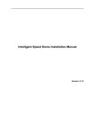
1
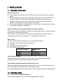
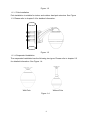
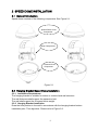
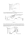
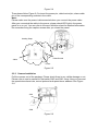
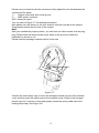
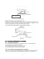
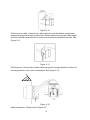
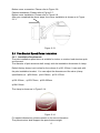
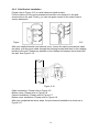
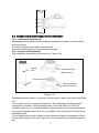
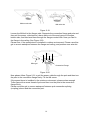
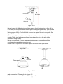
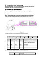
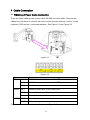
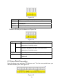
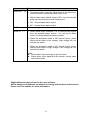
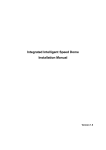
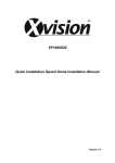
Speed Dome 66 Installation Manual
Table of Contents
1
INSTALLATION................................................................................................... 6
1.1
Installation Preparation ......................................................................................................................... 6
1.2
Installation Mode.................................................................................................................................... 6
1.2.1
Speed Dome Installation Mode....................................................................................................... 6
1.2.2
Bracket Installation Mode ................................................................................................................ 7
2
SPEED DOME INSTALLATION.......................................................................... 9
2.1
General Introduction.............................................................................................................................. 9
2.2
Hanging Bracket Speed Dome Installation ........................................................................................ 9
2.2.1
Installation Requirement .................................................................................................................. 9
2.2.2
Hanging Bracket Installation ........................................................................................................... 9
2.2.3
Camera Installation......................................................................................................................... 11
2.3
Corner Bracket Speed Dome Installation......................................................................................... 13
2.3.1
Installation Requirement ................................................................................................................ 13
2.3.2
Corner Bracket and Hanging Bracket Installation ...................................................................... 13
2.4
Pole Bracket Speed Dome Installation............................................................................................. 15
2.4.1
Installation Requirement ................................................................................................................ 15
2.4.2
Pole Bracket Installation ................................................................................................................ 16
2.5
Suspended Bracket Speed Dome Installation................................................................................. 17
2.5.1
Installation Requirement ................................................................................................................ 17
2.5.2
Accessories Installation ................................................................................................................. 17
2
Welcome
Thank you for purchasing our speed dome!
Please read the following safeguards and warnings carefully before you install
or use the product!
3
Important Safeguards and Warnings
Safety Measures
Qualified Engineer Needed
z
The installation engineer or maintenance engineer shall have corresponding
CCTV system installation certificate or maintenance qualification certificate.
z
The installation engineer or maintenance engineer shall have qualification
certificate for work at height.
z
The installation engineer or maintenance engineer shall have the basic
knowledge and operation technique for low-voltage cable layout and low-voltage
electronic cable connection.
z
Please read the installation manual carefully and keep it well for future reference,
z
We are not liable for any problems caused by unauthorized modifications or
attempted repair.
Lifting Appliance Requirement
z
Please select the proper speed dome installation mode and use the lifting
appliances at the safety environment.
z
The lifting appliances shall have the enough capacity to reach the installation
height.
z
The lifting appliances shall have safe performance.
Precautions
Safety Transportation
z
z
z
Heavy stress, violent vibration or water splash are not allowed during
transportation, storage and installation.
This series product must use split type package during the transportation.
We are not liable for any damage or problem result from the integrated package
during the transportation.
When device is malfunction
Shut down the device and disconnect the power cable immediately if there is smoke,
abnormal smell or abnormal function. Please contact your local retailer ASAP.
4
Do not try to dismantle or modify the device
z
z
z
There is risk of personal injury or device damage resulting from opening the shell.
Please contact your local retailer if there is internal setup or maintenance
requirement.
We are not liable for any problems caused by unauthorized modifications or
attempted repair.
Do not allow other object falling into the device
z
z
z
z
Please make sure there is no metal or inflammable, explosive substance in the
speed dome.
The above mentioned objects in the device may result in fire, short-circuit or
damage.
Please shut down the device and disconnect the power cable if there is water or
liquid falling into the camera. Please contact your local retailer ASAP.
Please pay attention to the camera. Avoid the sea water or rain to erode the
camera.
Handle carefully
Do not allow this series product fall down to the ground.
Avoid heavy vibration.
Installation Environment Requirement
z
z
This series speed dome should be installed in a cool, dry place away from direct
sunlight, inflammable, explosive substances and etc.
This series product shall be away from the strong electromagnetism radiant,
please keep it away from wireless power, TV transmitter, transformer and etc.
Daily Maintenance
z
z
z
Please use the soft cloth to clean dust on the shell, or you can use soft cloth with
cleaning liquid to clean the shell and then use soft cloth to make it dry.
Do not use gasoline, dope thinner or other chemical material to clean the shell. It
may result in shell transfiguration or paint flake.
Do not allow the plastic or rubber material to touch the shell for a long time. It
may result in paint flake.
5
1 INSTALLATION
1.1 Installation Preparation
Basic Requirement
z
z
z
All installation and operation here should conform to your local electrical safety
codes.
Before installation, please open the package and check all the components are
included. Please make sure the speed dome installation environment and
installation mode can meet your requirement. If there is special requirement,
please contact your local retailer for more information.
We assume no liability or responsibility for all the fires or electrical shock caused
by improper handling or installation.
Check installation space and installation location intension
Please make sure the installation environment has enough space to install the speed
dome and its corresponding bracket.
Please make sure the ceiling, wall, bracket can support the speed dome and its
corresponding installation component. The safety factor shall be 4X.
About cable
Please select the cable according to your transmission distance.
The minimum video coaxial-cable requirement is:
z 75 ohm.
z Full cable with copper conductor
z 95% knitted copper shield
International Model
Max Distance
(Ft\M)
RG59/U
750ft (229m)
RG6/U
1,000ft (305m)
RG11/U
1,500ft (457m)
Set dial switch button
Set dial switch button according to control protocol and speed dome address.
(Please refer to user’s manual for detailed information.)
Please keep all package material well for future use
Please keep speed dome package material well in case you need to send it back to
your local retailer or manufacturer for maintenance work.
Non-original package material may result in device damage during the transportation.
1.2 Installation Mode
1.2.1 Speed Dome Installation Mode
The integrated speed dome has the following installation modes:
6
z Embedded installation
z In-ceiling installation
z Bracket installation
1.2.2 Bracket Installation Mode
The bracket installation consists of the following modes:
z Hanging installation
z Corner installation
z Pole installation
z Suspended installation
The bracket installation is suitable for indoor and outdoor environment. The outdoor
speed dome has a sun-shade cover and it also has an internal heater device.
The outdoor speed dome IP standard is IP 66.
1.2.2.1 Hanging Installation
This series installation mode is suitable for indoor and outdoor hard wall structure.
See Figure 1-1. Please refer to chapter 2.2 for detailed information.
Figure 1-1
1.2.2.2 Corner Installation
The corner installation is suitable for indoor and outdoor hard wall structure
environment where the angel is 90 degrees. See Figure 1-2. Please refer to chapter
2.3 for detailed information.
7
Figure 1-2
1.2.2.3 Pole Installation
Pole installation is suitable for indoor and outdoor hard pole structure. See Figure
1-3. Please refer to chapter 2.4 for detailed information.
Figure 1-3
1.2.2.4 Suspended Installation
The suspended installation has the following two types. Please refer to chapter 2.5
for detailed information. See Figure 1-4.
With Pole
Without Pole
Figure 1-4
8
2 SPEED DOME INSTALLATION
2.1 General Introduction
Speed dome consists of the following components. See Figure 2-1.
Speed Dome Cover
Component
Body Component
External Cover
Component
Figure 2-1
2.2 Hanging Bracket Speed Dome Installation
2.2.1 Installation Requirement
The hanging bracket is suitable for indoor or outdoor hard wall structure.
The wall thickness shall support the expansion bolt.
The wall shall support the 4x speed dome weight.
2.2.2 Hanging Bracket Installation
Draw the hole position in the wall in accordance with the hanging bracket bottom
installation pole. Then dig holes. Please refer to Figure 2-2.
9
Figure 2-2
You can use socket head cap screw to fix hanging bracket and external cover
component. (Please install waterproof sealing cushion)
M5×12 socket head cap screw
External Cover Component
Hanging Bracket
Figure 2-3
After you installed bracket and external cover components, loosen captive screws
and open the panel. Draw the power cable through the hanging bracket and then fix
the bracket in the wall. Please pay attention to the waterproof between the bracket
and then wall. See Figure 2-4.
Power Cable
Captive Screws
10
Figure 2-4
Then please follow Figure 2-5 to insert the power pin, video/control pin, alarm cable
pin to the corresponding sockets in the outlet.
Note:
Please make sure the power is disconnected when you connect the power cable.
After you connected the cable to the power, please check LED light in the power
panel is on or not. You can refer to the error definition sheet for detailed information.
Do remember fixing the captive screws after you closed the panel.
Heating Strap
Video/Control
Alarm
Power
Figure 2-5
2.2.3 Camera Installation
Pull the camera out of the package. Please check there is any visible damage or not.
Please refer to user’s manual for dial switch SW2 and SW1 setup. Now you have set
the speed dome baud rate, control protocol and speed dome address. See Figure
2-6.
SW1
SW2
Figure 2-6
11
Please use your hand to hold the camera and then adjust the lock tab between the
camera and the panel.
1— Captive screw and semi-circle groove.
2— AMP socket connector
3/4/5- three pilot spool
You can refer to Figure 2-7 for detailed information.
Now please turn the camera in the lock direction until the lock tab of the camera
fixing bracket meets the lock line of the camera.
Note:
After you reached the proper position, you can hear two clear sounds such as ping,
ping. Please draw the black camera cover down to the ground to check the
installation is secure or not.
Please keep the package material well for future use.
2
5
4
3
1
6
Figure 2-7
Connect the steel safety rope (Loosen the hexagon domed cap nut of the external
cover and then push the safety rope to the squeeze screw, finally fix the hexagon
domed cap nut). Connect to the heating strips (insert the spring cable cap to the
heating strips cap.) See Figure 2-8.
12
Cable
Heating Strip
Steel Safety Rope
Figure 2-8
Please refer to Figure 2-9 to install bottom cover.
Please line the two round grooves of bottom cover side to the two captive screws on
the bottom cover side. The angel shall ranges from -5 degrees to +5 degrees. Then
you can push the bottom cover up and fix the captive screws.
You can find the lubricating grease in the accessories package.
Captive Screws
Round grooves
Lubricating Grease
Figure 2-9
2.3 Corner Bracket Speed Dome Installation
2.3.1 Installation Requirement
The corner installation speed dome is suitable for indoor or outdoor hard wall
environment where the angel is 90 degrees.
The wall thickness shall support the expansion bolt.
The wall shall support the 4x speed dome weight.
2.3.2 Corner Bracket and Hanging Bracket Installation
Take the corner bracket as template, draw the hole position in the 90 degrees wall.
Then you can dig holes and fix the M8 expansion bolts firmly. See Figure 2-10.
13
Figure 2-10
Pull the power cable, video/control, alarm cable through the bottom central hole,
waterproof grew and bracket central hole. Please reserve the enough cable length
and then use M8 expansion blot to fix the corner bracket pedestal in the wall. See
Figure 2-11.
Figure 2-11
Pull the power, video/control, alarm cable through the hanging bracket and then fix
the hang bracket in the corner accessories. See Figure 2-12.
Figure 2-12
Cable connection: Please refer to Figure 2-5.
14
Bottom cover connection: Please refer to Figure 2-8.
Camera installation: Please refer to Figure 2-7.
Bottom cover installation: Please refer to Figure 2-9.
After you completed the above steps, the corner installation is shown as in Figure
2-13.
Figure 2-13
2.4 Pole Bracket Speed Dome Installation
2.4.1 Installation Requirement
The pole installation speed dome is suitable for indoor or outdoor hard structure pole
environment.
The diameter of pole structure shall comply with the installation dimension of clamp.
Default factory clamp is six inches for the column of φ130-152mm. It can work with
the pole installation bracket. You can adjust the diameter and the value (clamp
specification) is : φ59-82mm、φ84-108mm、φ103-127mm
φ130-152mm、φ155-178mm、φ180-203mm
φ194-216mm.
The clamp is shown as in Figure 2-14.
Figure 2-14
For special dimensions, please contact us for more information.
The pole structure shall support the speed dome weight.
15
2.4.2 Pole Bracket Installation
Please refer to Figure 2-15 to install clamp and pole bracket.
Pull the cable out of the pole accessories and then use clamp to fix the pole
accessories to the pole. Finally, you can use glass cement to the output hole to
secure waterproof.
Figure
2-15
After you installed bracket and external cover, loosen the captive screws and open
the panel, pull the power cable through the hanging bracket and then fix the hanging
bracket to the wall. Please pay attention to the waterproof between the bracket and
the wall. See Figure 2-16.
Figure 2-16
Cable connection: Please refer to Figure 2-5.
Bottom cover: Please refer to Figure 2-8.
Camera installation: Please refer to Figure 2-7.
Bottom cover installation: Please refer to Figure 2-9.
After you completed the above steps, the pole bracket installation is shown as in
Figure 2-17.
16
Figure 2-17
2.5 Suspended Bracket Speed Dome Installation
2.5.1 Installation Requirement
Suspended bracket speed dome installation is suitable for indoor or outdoor hard
structure ceiling.
The ceiling thickness can install expansion bolt.
The ceiling shall support the 4x speed dome weight.
2.5.2 Accessories Installation
The installation accessories are shown as in Figure 2-18.
Straight
Pole
Connection flange
(With wire slot.)
Connection Stud
Connection flange
(Without wire slot)
Figure 2-18
Suspended bracket mainly is connection flange (with or without wire slot).See Figure
2-19.
You can select from your actual requirement. The suspended bracket standard
configuration consists of 200mm straight pole. There are 300mm or 500 mm
connection pole too. For special dimension, please contact us for more information.
If you use the flange without wire slot, you need to open a wire hole of 35mm in the
installation panel.
For the flange with wire slot, please use the connection flange as template to draw
out the pole position on the wall. Dig holes in the wall and then insert M6 expansion
bolt.
17
Without wire slot
With wire slot
Figure 2-19
Loosen the M4 bolt in the flanges side. Separate the connection flange and pole and
then pull the power, video/control, alarm cable out of the seal groove of flanges
bottom side, and then lead them through the flanges central hole. Now you can fix
the flange in the ceiling. See Figure 2-20.
Please note, if the speed dome is installed in outdoor environment. Please use silica
gel to secure waterproof between the flange and ceiling, and position near wire slot.
Silica gel
Connection Flange
Figure 2-20
Now please follow Figure 2-21 to pull the power cable through the pole and then turn
the pole to the connection flange firmly. Fix the M4 screw.
If the speed dome is installed in the outdoor environment, please enlace enough
Teflon tape at the screw thread of pole and then turn the pole to the connection
flange firmly.
Please use silica gel to secure waterproof between pole connection splicing
(coupling) sleeve and the connection port.
18
Teflon tape
M4 Screw
Silica gel
Figure 2-21
Please loosen the M4 bolt at the splicing sleeve of pole bottom (just a little will be
O.K), then turn the screw thread of the upper cover splicing sleeve in. Now pull the
power cable through the upper cover and then turn the upper cover to the pole
splicing sleeve firmly. Fix the M4 bolt. Loosen the captive screw in the panel. See
Figure 2-22.
Please note, if the speed dome is installed in outdoor environment, please enlace
enough Teflon tape at the screw thread of pole and then turn the pole to the
connection flange firmly.
Please use silica gel to secure waterproof between pole connection splicing
(coupling) sleeve and the connection port.
Please refer to Figure 2-22 to loosen captive screw and then open panel.
Teflon tape
M4 Screw
Figure 2-22
Cable connection: Please refer to Figure 2-5.
Bottom cover connection: Please refer to Figure 2-8.
19
Camera installation: Please refer to Figure 2-7.
Bottom cover installation. Please refer to Figure 2-9.
20
3 Protocol, Baud Rate, Address setup
Before you operate, you need to set protocol, baud rate and address.
Otherwise you can not control the product!
3.1 Protocol and Baud Rate Setup
Please configure the following settings before begin controlling dome:
z Protocol
z Baud rate
z Address
Note: Please reboot the speed dome to get all the setups activated!
Open the lower dome, the interface is shown as below. See Figure 2-1.
Figure 3-1
Please refer to the protocol sheets for detailed information.
Protocol
1
2
3
Baud rate
5
6
4
Parity
7
8
1
2
3
4
Communication Protocol
OFF
OFF
OFF
OFF
DH-SD(Compatible with China
industrial standard protocol)
ON
OFF
OFF
OFF
PELCO-D
OFF
ON
OFF
OFF
PELCO-P
X
X
X
X
Reserved
Please refer to the baud rate sheet for detailed information.
5
6
Baud Rate
21
OFF
OFF
9600bps
ON
OFF
OFF
4800bps
ON
2400bps
ON
ON
1200bps
Please refer to the parity setup sheet for detailed information.
7
8
Parity
OFF
OFF
NONE
ON
OFF
EVEN
OFF
ON
ODD
ON
ON
NONE
3.2 Set address dial switch
The encode mode adopts binary system. 1 to 8 is valid bit. The highest address bit is
255. You can refer to the following sheet for more information.
Address 1
2
3
4
5
6
7
8
1
1
2
3
4
5
6
7
8
……
254
255
OFF OFF OFF OFF OFF OFF OFF OFF
ON
OFF OFF OFF OFF OFF OFF OFF
OFF ON
OFF OFF OFF OFF OFF OFF
ON
ON
OFF OFF OFF OFF OFF OFF
OFF OFF ON
OFF OFF OFF OFF OFF
ON
OFF ON
OFF OFF OFF OFF OFF
OFF ON
ON
OFF OFF OFF OFF OFF
ON
ON
ON
OFF OFF OFF OFF OFF
OFF OFF OFF ON
OFF OFF OFF OFF
…………………………………………………………………
OFF ON
ON
ON
ON
ON
ON
ON
ON
ON
ON
ON
ON
ON
ON
ON
22
4 Cable Connection
4.1 RS485 and Power Cable Connection
There are three cable groups: power cable, RS 485 and video cable. Draw out the
cables from the dome to connect with main control devices (such as monitor, control
keyboard, DVR and etc.) and power adapter. See Figure 3-1 and Figure 3-2.
Figure 4-1
Figure 4-2
Name
485
A
Function
485-A. It is to control dome built-in PTZ.
B
485-B. It is to control dome built-in PTZ.
GND
Ground.
AUDIO OUT
Reserved audio port. Audio output port.
GND
Reserved audio port. Ground port audio.
IN
Reserved audio port. Audio connection port.
VIDEO GND
OUT
Ground port.
Video output port.
Power port connection interface is shown as in Figure 3-3.
23
Figure 4-3
Name
AC24V
Function
24V power port. Connect to the power cable.
EARTH
Ground port.
AC24V
24V power port. Connect to power cable.
Extension RS 485 port is shown as in Figure 3-4.
Figure 4-4
Name
485
+
Function
Extension peripheral 485 port. Such as control
temperature, humidity sensor.
-
Extension peripheral 485 port. Such as control
temperature, humidity sensor.
GND
Ground port.
+12V
External device power port. Provide power the
Peripheral.
4.2 Alarm Cable Connection
Open the dome cover and take PTZ chip core out. Turn the core upside down; you
can see the alarm port. See Figure 3-5.
Figure 4-5
24
Name
Alarm out:1-2
Function
z
Two alarm output channels. When there is an alarm from
current channel, system activates relay or not.
z
Alarm output relay default setup is NO. You can use the
jump-cap near the power board relay to set.
z
NO:Normal open alarm output.
NC:Normal close alarm output.
Alarm input ground end.
z
GND
Alarm in:1-7
z
Seven alarm input channels. It is to receive relay signal
from the external alarm source. You can go to dome
menu to activate specified preset or patter.
z
When the activation mode is NO (normal open), dome
alarms when there is low voltage. High voltage will not
activate the alarm.
z
When the activation mode is NC (normal close), dome
alarms when there is high voltage. Low voltage will not
activate the alarm.
Note:
z Dome alarm input message is ground mode.
z Dome alarm input signal are two modes: normal open
and normal close.
Slight difference may be found in the user interface.
All the designs and software are subject to change without prior written notice.
Please visit our website for more information.
25