1
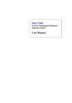
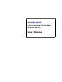
ADAM-6520
5-Port Industrial 10/100 Mbps
Ethernet Switch
User Manual
Copyright
The documentation and the software included with this product are copyrighted 2005 by Advantech Co., Ltd. All rights are reserved. Advantech
Co., Ltd. reserves the right to make improvements in the products
described in this manual at any time without notice. No part of this manual may be reproduced, copied, translated or transmitted in any form or
by any means without the prior written permission of Advantech Co., Ltd.
Information provided in this manual is intended to be accurate and reliable. However, Advantech Co., Ltd. assumes no responsibility for its use,
nor for any infringements of the rights of third parties, which may result
from its use.
Acknowledgements
Intel and Pentium are trademarks of Intel Corporation.
Microsoft Windows and MS-DOS are registered trademarks of
Microsoft Corp.
All other product names or trademarks are properties of their respective
owners.
This Manual Covers the Following Models
• ADAM-6520
• ADAM-6520I
Part No. 2003652011
3rd Edition
Printed in Taiwan
October 2005
ADAM-6520 User Manual
ii
Product Warranty (2 years)
Advantech warrants to you, the original purchaser, that each of its products will be free from defects in materials and workmanship for two years
from the date of purchase.
This warranty does not apply to any products which have been repaired or
altered by persons other than repair personnel authorized by Advantech,
or which have been subject to misuse, abuse, accident or improper installation. Advantech assumes no liability under the terms of this warranty as
a consequence of such events.
Because of Advantech’s high quality-control standards and rigorous testing, most of our customers never need to use our repair service. If an
Advantech product is defective, it will be repaired or replaced at no
charge during the warranty period. For out-of-warranty repairs, you will
be billed according to the cost of replacement materials, service time and
freight. Please consult your dealer for more details.
If you think you have a defective product, follow these steps:
1.
Collect all the information about the problem encountered. (For
example, CPU speed, Advantech products used, other hardware
and software used, etc.) Note anything abnormal and list any
onscreen messages you get when the problem occurs.
2.
Call your dealer and describe the problem. Please have your manual, product, and any helpful information readily available.
3.
If your product is diagnosed as defective, obtain an RMA (return
merchandize authorization) number from your dealer. This allows
us to process your return more quickly.
4.
Carefully pack the defective product, a fully-completed Repair and
Replacement Order Card and a photocopy proof of purchase date
(such as your sales receipt) in a shippable container. A product
returned without proof of the purchase date is not eligible for warranty service.
5.
Write the RMA number visibly on the outside of the package and
ship it prepaid to your dealer.
iii
Declaration of Conformity
CE
This product has passed the CE test for environmental specifications
when shielded cables are used for external wiring. We recommend the use
of shielded cables. This kind of cable is available from Advantech. Please
contact your local supplier for ordering information.
FCC Class A
Note: This equipment has been tested and found to comply with the limits
for a Class A digital device, pursuant to part 15 of the FCC Rules. These
limits are designed to provide reasonable protection against harmful
interference when the equipment is operated in a commercial environment. This equipment generates, uses, and can radiate radio frequency
energy and, if not installed and used in accordance with the instruction
manual, may cause harmful interference to radio communications. Operation of this equipment in a residential area is likely to cause harmful interference in which case the user will be required to correct the interference
at his own expense.
Technical Support and Assistance
Step 1. Visit the Advantech web site at www.advantech.com/support
where you can find the latest information about the product.
Step 2. Contact your distributor, sales representative, or Advantech's customer service center for technical support if you need additional
assistance. Please have the following information ready before
you call:
- Product name and serial number
- Description of your peripheral attachments
- Description of your software (operating system, version, application software, etc.)
- A complete description of the problem
- The exact wording of any error messages
Document Feedback
To assist us in making improvements to this manual, we would welcome
comments and constructive criticism. Please send all such - in writing to:
[email protected]
ADAM-6520 User Manual
iv
Contents
Chapter
Chapter
1 Overview .......................................................... 2
1.1
Introduction ....................................................................... 2
1.2
1.3
1.4
Features ............................................................................. 3
Specifications .................................................................... 4
Ordering Information ........................................................ 5
1.1.1
1.1.2
1.1.3
1.1.4
1.1.5
High-Speed Transmission .............................................. 2
Flexible Mounting .......................................................... 2
Advanced Protection for Power Line and Ethernet Port 2
Wide Operating Temperature Range ............................. 3
Easy Troubleshooting .................................................... 3
2 Installation ....................................................... 8
2.1
2.2
Packing List....................................................................... 8
Top / Front / Rear View .................................................... 9
2.2.1
Dimensions .................................................................... 9
Figure 2.1:Top View ...................................................... 9
Figure 2.2:Front Panel ................................................... 9
Figure 2.3:Rear View ..................................................... 9
2.3
LED Indicators ................................................................ 10
2.4
Mounting ......................................................................... 11
2.5
2.6
Table 2.1:ADAM-6520 LED Definitions .................... 10
Figure 2.4:Panel Mounting .......................................... 11
Figure 2.5:DIN Rail Mounting .................................... 12
Figure 2.6:Piggyback Stacking .................................... 12
Network Connection ....................................................... 13
2.5.1
2.5.2
Connection to Devices ................................................. 13
Connection to other Hubs or Switches ........................ 13
Power Connection ........................................................... 14
v
ADAM-6520 User Manual
vi
CHAPTER
1
2
Overview
This chapter gives an overview of the
ADAM-6520’s features and full specifications.
Sections include:
• Introduction
• Features
• Specifications
• Ordering Information
Chapter 1 Overview
1.1 Introduction
ADAM-6520 is a 5-port industrial-grade 10/100 Mbps Ethernet switch
for fast and cost-efficient network expansion. It connects up to 5 workstations and auto-detects both 10 and 100 Mbps network speeds. Moreover,
ADAM-6520 supports auto crossover to provide a flexible networking
environment, connecting to the network with any port.
ADAM-6520 provides three methods for mounting in an industrial environment: DIN rail, wall/panel, or piggyback stacking. ADAM-6520 has a
flexible input voltage range of +10~30 VDC at the terminal block. And,
the operating temperature of ADAM-6520 is from -10 to 70° C while
ADAM-6520I is from -40 to 85° C. The above features make ADAM6520 more stable and reliable than normal Ethernet switches. Thus,
ADAM-6520 is especially suitable for industrial environments with
Ethernet networking like: semiconductor factories, warehouses, conveyer
belt systems and more.
1.1.1 High-Speed Transmission
ADAM-6520 includes a switch controller that automatically senses transmission speeds (10/100 Mbps). The RJ-45 interface also supports autodetection, so MDI or MDI-X is automatically selected and a crossover
cable is not required. All Ethernet ports have memory buffers that support
the store-and-forward mechanism. This assures that data is properly
transmitted.
1.1.2 Flexible Mounting
Due to its versatility and innovative design, ADAM-6520 can be fixed in
three ways: DIN rail, panel and piggyback mounting.
1.1.3 Advanced Protection for Power Line and Ethernet
Port
The power line of ADAM-6520 supports up to 3000 VDC surge protection, which secure equipment against unregulated voltage and make systems safer and more reliable. Meanwhile, 4000 VDC ESD protection for
the Ethernet ports makes ADAM-6520 more suitable for harsh environments.
ADAM-6520 User Manual
2
1.1.4 Wide Operating Temperature Range
The operating temperature of ADAM-6520 is from -10 to 70° C, while
ADAM-6520I offers a very wide range from -40 to 85° C. With such a
wide range you can use ADAM-6520 and ADAM-6520I in some of the
harshest industrial environments that exist.
1.1.5 Easy Troubleshooting
There are six LED indicators supplied to aid troubleshooting for ADAM6520. Besides one common collision LED, each port has a pair of LEDs
to indicate link status and port activity. That makes it easy to indicate collisions, link status, power failure and data reception for on-site diagnostics.
1.2 Features
• Provides 5 x 10/100 Mbps Ethernet ports with RJ-45 connector
• Supports full/half duplex flow control
• Supports MDI/MDI-X auto crossover
• Provides broadcast storm protection
• Embedded switch controller, supports auto-negotiation
• Embedded memory buffer, supports store-and-forward transmission
• Supports +10 ~ 30 VDC voltage
• Provides 3000 VDC surge protection for power line
• Provides 4000 VDC Ethernet ESD protection
• Provides flexible mountings: DIN rail, panel, piggyback stacking
• Supports wide-range operating temperature
3
Chapter 1
1.3 Specifications
Communications
• Compatibility: IEEE 802.3, IEEE 802.3u
• LAN: 5 x 10/100 Base-TX
• Transmission Distance: 100 m
Interface
• Connectors: 5 x RJ-45 (10/100 Mbps),
1 x Plug-in screw terminal for power input
• Indicators: LEDs for : Power, 10/100 Mbps
Power
• Input Voltage: Unregulated 10 ~ 30 VDC
• Power Consumption: Max. 2.4 W
Mechanism
• Enclosure: IP30, ABS+PC
• Dimensions: 70 x 100 x 25 mm (W x H x D)
• Mounting: DIN 35 rail, stack, wall
Protection
• ESD Protection: 4000 VDC (Ethernet)
• Surge Protection: 3000 VDC (Power)
Environment
• Operating Temperature:
DIN rail or wall mounted:
ADAM-6520: -10 ~ 70° C (14~158° F)
ADAM-6520I: -40 ~ 85° C (-40~185° F)
Stack mounted:
ADAM-6520: -10 ~ 60° C (14~140° F)
ADAM-6520I: -40 ~ 75° C (-40~167° F)
• Storage Temperature:
ADAM-6520: -20 ~ 80° C (-4~176° F)
ADAM-6520I: -50 ~ 95° C (-58~203° F)
• Operating Humidity: 20 to 95% (non-condensing)
• Storage Humidity: 0 to 95% (non-condensing)
ADAM-6520 User Manual
4
Certifications
• Safety: UL 60950, CAN/CSA-C22.2 No.60950
• EMC: FCC Part 15 CISPR 22/EN55022 Class A
EN55024
EN6100-3-2
EN6100-3-3
EN6100-4-2
EN6100-4-3
EN6100-4-4
EN6100-4-5
EN6100-4-6
EN6100-4-8
EN6100-4-11
• MTBF: 416,000 hours
1.4 Ordering Information
• ADAM-6520
5-Port Industrial 10/100 Mbps Ethernet Switch
• ADAM-6520I 5-Port Industrial 10/100 Mbps Ethernet Switch w/
Wide Operating Temp.
5
Chapter 1
ADAM-6520 User Manual
6
CHAPTER
2
2
Installation
In this chapter, you will be given an
overview of the ADAM-6520 hardware
installation procedure.
Sections include:
• Packing List
• Top / Front / Rear View
• LED Indicators
• Connecting the Hardware
• Network Connection
• Power Connection
Chapter 2 Installation
2.1 Packing List
Before setting up the system, check that the items listed below are
included and in good condition. If any item does not accord with the
table, please contact your dealer immediately.
• 1 x ADAM-6520
• 1 x INET CD-ROM
• 1 x DIN rail mounting adapter
• 1 x Panel mounting bracket
ADAM-6520 User Manual
8
2.2 Top / Front / Rear View
2.2.1 Dimensions
Figure 2.1: Top View
Figure 2.2: Front Panel
Figure 2.3: Rear View
9
Chapter 2
2.3 LED Indicators
There are six network status LEDs located on the top panel of ADAM6520, one for power, and one for each of the network ports.
Table 2.1: ADAM-6520 LED Definitions
LED
Color
State
Description
Power
Green
On
Power is on
Off
Power is off
100/10M
(Port 1 ~5)
Green (link)
On
Connected to network
Off
Not connected to network
On
Linked to 100 Mbps network
Off
Linked to 10 Mbps network
Orange (speed)
ADAM-6520 User Manual
10
2.4 Mounting
Due to its versatility and innovative design, the ADAM-6520 can be:
• Fixed to a wall or panel
• Fixed to a DIN Rail.
• “Piggyback” stacked
Panel Mounting
ADAM modules can be attached to a wall using the included brackets.
Each bracket comes with four screws; first attach the bracket to the bottom of the ADAM module. Next, screw the bracket to the wall.
Figure 2.4: Panel Mounting
11
Chapter 2
DIN Rail Mounting
You can mount ADAM modules on a standard 35 mm DIN Rail. First,
use two screws to attach the DIN rail bracket to the ADAM module.
Because ADAM modules use special hex head slotted shoulder screws,
the tops of the screws will be even with the front of the module. Snap the
module onto the DIN rail.
Figure 2.5: DIN Rail Mounting
Piggyback Stack
Several ADAM modules can be stacked as seen in the figure below
Figure 2.6: Piggyback Stacking
ADAM-6520 User Manual
12
2.5 Network Connection
2.5.1 Connection to Devices
Each of the switch’s twisted-pair ports can be used to connect to a controller or other devices. Use a straight-through twisted-pair cable with RJ45 connectors on both ends. The twisted-pair cable extended from a
twisted-pair port is called a “twisted-pair segment”. It can be up to 100
meters long. You can connect any RJ-45 (MDI-X) station port on the
switch to any device that uses a standard network interface such as a
workstation or server.
2.5.2 Connection to other Hubs or Switches
ADAM-6520 has five RJ-45 ports that support connections to 10 or 100
Mbps Ethernet networks, and half or full-duplex operation. ADAM-6520
can be connected to other hubs or switches via a two-pair straight through
cable or crossover cable. The connection can be made from any port on
ADAM-6520 (MDI-X) to other hubs or switches by either their MDI-X
port or uplink MDI port.
ADAM-6520 supports auto-crossover, so each port allows you to connect
switches together and expand an existing network easily using either
straight through or a crossover Ethernet cable. You can connect any RJ45(MDI-X) port on the switch to a device like a switch, bridge or router.
13
Chapter 2
2.6 Power Connection
You should take the following steps to connect ADAM-6520 to power.
1.
Connect the power cable to the two connectors.
2.
Connect the power cable to a power adapter.
ADAM-6520 User Manual
14