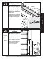
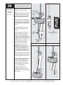
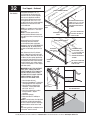
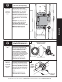
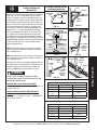
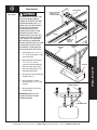
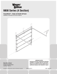
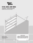
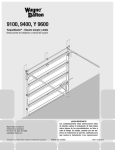
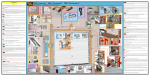
1
Tools Needed:
None
Shake the TorqueMaster® spring tube
gently to extend the winding shafts out
about 5" on each side. For single
spring applications, there will be no left
hand spring in the TorqueMaster®
spring tube.
WINDING
SHAFT
SPLINES
RIGHT HAND
CABLE DRUM
FLAGANGLE
Lift the TorqueMaster® spring tube and
rest it on the top of the flagangles.
Orient TorqueMaster® spring tube so
that back of opener is flat against
header/mounting surface.
CABLE
DRUM
NOTE: Cable drums are marked right
and left hand. Cable drums and
TorqueMaster® spring tube are cam
shaped to fit together only one way.
To install the cable drum, slide the
correct cable drum over the winding
shaft until the cable drum seats against
the TorqueMaster® spring tube. The
winding shaft must extend past the
cable drum far enough to expose the
splines and the groove. Align the
winding shaft groove with the round
notch in the flagangle.
COUNTERBALANCE
CABLE
GROOVE
WINDING
SHAFT
GROOVE
TORQUEMASTER®
SPRING TUBE
ROUND
NOTCH
FLAGANGLE
For Double Spring Applications:
Repeat for opposite side.
For Single Spring Applications: Insert
the loose winding shaft into the left
hand cable drum prior to sliding the
cable drum over the TorqueMaster®
spring tube.
NOTE: On single spring applications,
take care in handling the loose winding
shaft (left side) so that it does not slide
back into the TorqueMaster® spring
tube.
ROUND
NOTCH
WINDING
SHAFT
®
TORQUEMASTER
SPRING TUBE
CABLE
DRUM
Left Hand Side
Single Spring Application
GROOVE
ROUND
NOTCH
LEFT HAND
CABLE DRUM
TORQUEMASTER®
SPRING TUBE
LOOSE
WINDING
SHAFT
Please Do Not Return This Product To The Store. Call Us Directly! Our Trained Technicians Will Answer Your Questions and/or Ship Any Parts
You May Need. You can reach us Toll Free at 1-888-827-3667 for Consumer Assistance or online at www.wayne-dalton.com
21
INSTALLATION
18
Cable Drum Installation
TORQUEMASTER®
SPRING TUBE
19
Tools Needed:
None
Drive Gear Installation
CABLE
DRUM
Beginning with the right hand side,
lubricate entire circumference of the 36
tooth worm gear with the lubricating oil
provided. Slide the 36 tooth worm gear
onto the winding shaft splines until it
touches the flagangle.
NOTE: On single spring applications, no
36 tooth worm gear is required on the
left side.
WINDING
SHAFT
SPLINES LUBRICATING
OIL
36 TOOTH
WORM GEAR
FLAGANGLE
NOTE: If additional lubricating oil is
needed, use “Dura Lube® Engine Oil
Treatment”.
CABLE
DRUM
36 TOOTH
WORM GEAR
WINDING
SHAFT
20
Tools Needed:
None
End Brackets
END BRACKET
IMPORTANT: WARNING TAGS MUST BE
SECURELY ATTACHED TO BOTH END
BRACKETS.
WARNING
TAG
Slide the right hand end bracket over
the drive gear and fasten to the
flagangle using a #10 self-tapping
screw. Drill 3/16” pilot holes into jamb
for the lag screws. Secure end bracket
and the flagangle to the jamb using (2)
5/16” x 1-5/8" lag screws.
Repeat for left hand side.
(2) 5/16” X 1-5/8”
LAG SCREWS
#10 PHILLIPS
HEAD
SCREW
22
Please Do Not Return This Product To The Store. Call Us Directly! Our Trained Technicians Will Answer Your Questions and/or Ship Any Parts
You May Need. You can reach us Toll Free at 1-888-827-3667 for Consumer Assistance or online at www.wayne-dalton.com
21
Tools Needed:
None
WINDING
SHAFT INSIDE
END BRACKET
Counter Installation
COUNTER
GEAR
Install the right side counter gear, with
the missing tooth toward the outside
and away from the end bracket. Press
the counter gear onto the end bracket
until snaps engage.
Select the right hand counter cover and
align the hex of the counter cam with
the end of the winding shaft. Also, align
the “0” on the counter cover with the
raised rib on the end bracket. Press the
counter cover against the counter gear
until it locks into place.
MISSING
TOOTH
RAISED RIB
“0”
COUNTER
COVER
HEX OF THE
COUNTER CAM
Repeat for left hand side for double
spring applications.
INSTALLATION
NOTE: No 36 tooth worm gear, counter
gear or counter cover is required on left
hand side for single spring applications.
Only an end bracket is needed.
IMPORTANT: AT THIS TIME DO NOT
WIND COUNTERBALANCE SPRINGS!
22
Tools Needed:
Power Drill
Securing Center Bracket
Assembly
NOTE: If you are installing an idrive®
opener on your garage door, skip this step
and continue with Step 23.
CENTER
BRACKET
BUSHING
ASSEMBLY
1/8” Drill Bit
7/16” Socket
Driver
NOTE: If you are not installing an idrive®
opener on your garage door, you must
install the center bracket bushing
assembly. Follow these instructions for
non-idrive® operated garage doors.
NOTE: If you are installing a DoorMaster™
opener, see optional DoorMaster™ Bracket
installations on page 32, Figure B.
To locate the center bracket, mark the
header halfway between the flagangles
and level the TorqueMaster® spring tube.
Drill 1/8” pilot holes into header for the
lag screws. Fasten the metal bracket to
the header using (2) 5/16” X 1-5/8” lag
screws.
(2) 5/16” X 1-5/8”
HEX HEAD LAG
SCREWS
NOTE: Upon completion of this step, continue with Step 27.
Please Do Not Return This Product To The Store. Call Us Directly! Our Trained Technicians Will Answer Your Questions and/or Ship Any Parts
You May Need. You can reach us Toll Free at 1-888-827-3667 for Consumer Assistance or online at www.wayne-dalton.com
23
23
Positioning Support Bracket
Tools Needed:
NOTE: See idrive® main installation and
owners manual for idrive® parts.
TORQUEMASTER®
SPRING TUBE
45 ANGLE
ANTENNA
WIRE
MOUNTING
SURFACE
Power Drill
1/8” Drill Bit
7/16” Socket
Driver
NOTE: idrive® must be installed on a
solid mounting surface.
Locate the mounting surface. Remove
(2) 1/4”-20 flange nuts from bottom of
opener.
NOTE: Do not discard flange nuts.
Place the support bracket underneath
opener, to the right side of motor,
centered on mounting surface. Using a
tape measure, level the bottom of the
TorqueMaster® spring tube to the top of
the door section with the idrive® resting
on the support bracket. Once
TorqueMaster® spring tube is level, drill
1/8” pilot holes for the lag screws. Then
secure support bracket to the mounting
surface with (2) 1/4” x 1-1/2" lag
screws.
1/4” X 1-1/2”
LAG SCREWS
(HEADER)
1/4” - 20
FLANGE NUTS
TOP OF DOOR
MOUNTING
STUDS
IMPORTANT: TORQUEMASTER® SPRING
TUBE MUST BE LEVEL AFTER SUPPORT
BRACKET IS FASTENED TO MOUNTING
SURFACE.
NOTE: If wood mounting surface is
behind dry wall, use 1/4” x 2” lag
screws.
Lift and slide the opener over the
support bracket, aligning the mounting
studs with the bracket slots. Loosely
fasten to mounting studs with the (2)
1/4”-20 flange nuts.
SUPPORT
BRACKET
MOUNTING
STUDS
SUPPORT
BRACKET
TORQUEMASTER®
SPRING TUBE
NOTE: Do not tighten 1/4”-20 flange
nuts to opener studs at this time. You
will be instructed when to tighten them
in the idrive® main installation and
owners manual.
Remove the temporary orange label
holding the antenna wire. Straighten
antenna wire and angle it 45 degrees to
the right.
NOTE: Do not coil the antenna wire.
This will reduce the radio signal range.
BRACKET
SLOTS
(2) 1/4” - 20
FLANGE NUTS
“X”
“X”
“X”
TOP SECTION
USING A TAPE MEASURE, MAINTAIN AN EQUAL MEASUREMENT “X”
(TOP OF DOOR TO BOTTOM OF TORQUEMASTER® TUBE) AT BOTH
ENDS AND THE CENTER.
24
Please Do Not Return This Product To The Store. Call Us Directly! Our Trained Technicians Will Answer Your Questions and/or Ship Any Parts
You May Need. You can reach us Toll Free at 1-888-827-3667 for Consumer Assistance or online at www.wayne-dalton.com
24
Tools Needed:
Pliers
Attaching Disconnect Cables
S-HOOK
NOTE: See idrive® main installation and
owners manual for idrive® parts.
DISCONNECT
CABLE
HOLE IN RIGHT
END BRACKET
Attach the loose disconnect cable
(located in opener hardware bag) to the
opener with the “S” hook. Close both
ends of the “S” hook (with pliers) to lock
assembly together.
Thread the disconnect cable (behind the
counterbalance cable) through the hole
in the right hand end bracket; remove
all slack between opener and right end
bracket.
RIGHT SIDE OF
END BRACKET
CLOSE “S” HOOK
25
Tools Needed:
Pencil
Tape measure
1/8” Drill Bit
7/16” Socket
Driver
INSTALLATION
HOLE IN
END BRACKET
Mounting Disconnect
Handle Bracket
NOTE: See idrive® main installation and
owners manual for idrive® parts.
Mark a location on the right jamb, 6
feet above the floor to mount the
disconnect handle bracket.
Drill 1/8” pilot holes for the lag screws.
Power Drill
Align top of the bracket with the mark.
Fasten bracket to the jamb with
(2) 1/4” x 1-1/2" lag screws.
6ft
(2) 1/4” X 1-1/2”
LAG SCREWS
DISCONNECT
HANDLE BRACKET
Please Do Not Return This Product To The Store. Call Us Directly! Our Trained Technicians Will Answer Your Questions and/or Ship Any Parts
You May Need. You can reach us Toll Free at 1-888-827-3667 for Consumer Assistance or online at www.wayne-dalton.com
25
26
Tools Needed:
Phillips head
screwdriver
Wire cutters
Attaching Disconnect Handle
NOTE: See idrive® main installation and
owners manual for idrive® parts.
NOTE: Bring motor to the down position
by pulling the disconnect cable, insure
opener disconnect teeth are engaged
before installing disconnect handle.
Start the #6-20 x 1/2" screw into the
disconnect handle. Thread the disconnect
cable through the top of the disconnect
handle bracket and then the disconnect
handle.
UPPER POSITION
#6-20 X 1/2”
SCREW
HANDLE
Locate the disconnect handle in full
upper position of disconnect handle
bracket.
Remove all disconnect cable slack
between the opener and the top of the
disconnect handle bracket. Tighten
#6-20 x 1/2" screw into the disconnect
handle until snug, and then tighten screw
an additional 1 to 1-1/2 turns to secure
disconnect cable to the disconnect
handle. Trim off excess cable from
bottom of the disconnect handle.
DISCONNECT
CABLE
EMERGENCY DISCONNECT
LABEL
DISCONNECT
HANDLE
BRACKET
MANUAL OPERATED POSITION
MOTOR OPERATED POSITION
CAUTION: PULL CABLE ONLY TAUT
ENOUGH TO REMOVE THE CABLE SLACK.
PULLING THE CABLE MORE COULD
CAUSE OPENER TO DISCONNECT FROM
THE TORQUEMASTER® SPRING TUBE.
Apply emergency disconnect label next
to the mounted bracket. Use mechanical
fasteners if adhesive will not adhere.
Using the emergency disconnect, pull
disconnect handle downwards and
place it in the manual door operated
position (Use disconnect label for
reference). Motor will be rotated 90°
from its packaged position.
If motor does not pivot 90°, see
troubleshooting section in the main
installation and owners manual of your
idrive® opener
26
Please Do Not Return This Product To The Store. Call Us Directly! Our Trained Technicians Will Answer Your Questions and/or Ship Any Parts
You May Need. You can reach us Toll Free at 1-888-827-3667 for Consumer Assistance or online at www.wayne-dalton.com
27
Tools Needed:
Vice Clamp
Securing Door
for Spring Winding
Place vice clamps onto both vertical
tracks just above the third roller. This is
to prevent the garage door from raising
while winding counterbalance springs.
WARNING
FAILURE TO PLACE VICE CLAMPS
ONTO VERTICAL TRACK CAN
ALLOW DOOR TO RAISE AND
CAUSE SEVERE OR FATAL
INJURY.
PLACE VICE
CLAMPS ABOVE
3RD ROLLER
IMPORTANT: DO NOT USE IMPACT GUN
TO WIND SPRING(S).
28
Tools Needed:
Locking Pliers
Flat Tip
Screwdriver
TRACK
INSTALLATION
VICE CLAMPS
ATTACHED TO
INNER RAIL
OF TRACK
Cable Adjustments
Rotate the cable drum until the set
screw faces directly away from the
header. TorqueMaster® spring tube cam
peak should be pointing straight up.
COUNTERBALANCE
CABLE
CABLE
DRUM
CAM PEAK
STRAIGHT UP
Beginning with the right side, loosen
the set screw approximately 2 turns, to
adjust cable. Using locking pliers, pull
on the end of the cable to remove all
cable slack.
Check to ensure the cable is aligned
and seated in the first groove of the
cable drum. Snug the set screw, then
tighten an additional 1-1/2 turns. Cut
excess cable.
SET SCREW
Please Do Not Return This Product To The Store. Call Us Directly! Our Trained Technicians Will Answer Your Questions and/or Ship Any Parts
You May Need. You can reach us Toll Free at 1-888-827-3667 for Consumer Assistance or online at www.wayne-dalton.com
27
29
Tools Needed:
Power Drill
7/16" Socket
Driver
Winding Bolt Rotation
See chart in Step 30 for proper spring
tension setting.
WINDING
BOLT
Beginning with the right hand side,
ensure the cable is in the first groove of
the cable drum. Apply light pressure to
the canoe clip on counter cover while
winding springs.
Using a power drill (high torque/gear
reduced to 1300 RPM preferred) with a
7/16" socket, carefully rotate right hand
winding bolt clockwise, until counter
shows 2-3 turns.
CANOE CLIP
This will keep the counterbalance cable
taut while adjusting the left hand side
counterbalance cable. Adjust left hand
counterbalance cable tension. (refer to
Step 28)
NOTE: Single spring applications require
no spring winding on left hand side, but
need cable tension adjusted.
NOTE: Ensure counterbalance cable
tension is equal for both sides prior to
fully winding spring(s) to appropriate
number of turns. If cable tension is
unequal refer to Step 28.
30
Tools Needed:
Power Drill
7/16” Socket
Driver
7/16" Wrench
28
Setting Spring Tension
NOTE: Apply light pressure to the canoe clip on the
counter cover while winding spring(s).
See the Spring Turn chart.
For SINGLE SPRING applications, return to the right hand
side and carefully rotate the winding bolt head clockwise
until the counter shows the correct number of turns for
your door.
For DOUBLE SPRING applications, remain on the left
hand side and carefully rotate the winding bolt head
clockwise until the counter shows the correct number of
turns for your door. Then return to the right hand side and
wind the right hand spring to the required number of
turns.
IMPORTANT: DO NOT OVERWIND.
After spring is wound, hold the lock nut (in back of end
bracket) stationary on the right hand side with a 7/16”
wrench while rotating the winding bolt clockwise until
snug. Tightening of the lock nut prevents spring from
unwinding. Repeat for opposite side for double spring
TorqueMaster® systems.
IMPORTANT: CAUTIOUSLY REMOVE VICE CLAMPS FROM
VERTICAL TRACKS. ADJUSTMENTS TO THE
RECOMMENDED NUMBER OF TURNS MAY BE REQUIRED.
AFTER REAR SUPPORT ASSEMBLY IS COMPLETE (STEP
32), CHECK DOOR BALANCE. IF DOOR RAISES OFF FLOOR
UNDER SPRING TENSION ALONE, REDUCE SPRING
TENSION UNTIL DOOR RESTS ON THE FLOOR. IF THE
DOOR IS HARD TO RAISE OR DRIFTS DOWN ON ITS OWN,
ADD SPRING TENSION. AN UNBALANCED DOOR SUCH AS
THIS CAN CAUSE IDRIVE® OPERATION PROBLEMS.
15
.5
SPRING TENSION
SAMPLE SETTING
LOCK NUT
7/16”
WRENCH
NOTE: For 7’ high doors, 8’, 9’, 10’, 16’ or 18’ wide with
windows, the recommended number of spring turns is 15.
RECOMMENDED SPRING TURNS
Door Height
idrive® Operated
Doors 11’-11”
Wide or Less
Manually Operated Door,
and idrive® Operated
Doors 12’ Wide or Greater
7’-0”
15-1/2
16
8’-0”
17-1/2
18
Please Do Not Return This Product To The Store. Call Us Directly! Our Trained Technicians Will Answer Your Questions and/or Ship Any Parts
You May Need. You can reach us Toll Free at 1-888-827-3667 for Consumer Assistance or online at www.wayne-dalton.com
31
Tools Needed:
None
DRUM
WRAP
Drum Wrap Installation
Drum wraps are identified as right and
left hand.
OUTSIDE
FLANGE
To install, place the drum wrap over the
cable drum and under the idrive®
disconnect cable (right hand side). Align
the outside flange over the outside edge
of the cable drum and push the drum
wrap down onto the cable drum. Repeat
for left hand side.
CABLE
DRUM
NOTE: Drum wraps must be installed to
prevent cable from becoming tangled.
INSTALLATION
IMPORTANT: RIGHT AND LEFT HAND
ARE ALWAYS DETERMINED FROM INSIDE
THE BUILDING LOOKING OUT.
CABLE
DRUM
DRUM
WRAP
32
Tools Needed:
Ratchet Wrench
1/2” Socket
1/2” Wrench
(2) Vice Clamps
Tape Measure
Level
Hammer
Rear Support
WARNING
DOOR IN THE
UP POSITION
KEEP HORIZONTAL TRACK
PARALLEL AND WITHIN 3/4”
MAXIMUM OF DOOR EDGE,
OTHERWISE DOOR COULD FALL,
RESULTING IN SEVERE INJURY OR
DEATH.
Raise the door until the top section
and half of the next section are in a
horizontal position. Do not raise door any
further since the horizontal tracks are
not yet supported at the rear.
WARNING
3/4”
VICE
CLAMPS
DOOR EDGE
RAISING DOOR FURTHER CAN
RESULT IN DOOR FALLING AND
CAUSE SEVERE INJURY OR
DEATH.
Clamp a pair of vice clamps on the
vertical tracks just above the second
roller on one side, just below the second
roller on the other side. This will prevent
the door from raising or lowering while
installing the rear support.
VERTICAL
TRACK
HORIZONTAL
TRACK
Please Do Not Return This Product To The Store. Call Us Directly! Our Trained Technicians Will Answer Your Questions and/or Ship Any Parts
You May Need. You can reach us Toll Free at 1-888-827-3667 for Consumer Assistance or online at www.wayne-dalton.com
29
32
Tools Needed:
Rear Support - Continued
SOUND FRAMING MEMBERS
Using perforated angle, 5/16” x 1
5/8” hex head lag screws and 5/16”
bolts with nuts (may not be supplied),
fabricate rear support for horizontal
tracks. Attach horizontal tracks to the
rear supports with 5/16”-18 x 1-1/4”
hex bolts and nuts (may not be supplied).
Horizontal tracks must be level and
parallel with door.
NOTE: If rear supports are to be installed
over drywall, use 5/16” x 2” hex head
lag screws.
NOTE: If an idrive® opener will be
installed, position horizontal tracks one
hole above level when securing it to rear
supports.
Adjust weather seal (if necessary).
Permanently attach the weather
seal to both door jambs and header.
(Temporarily attached in PREPARING THE
OPENING on page 10.) Avoid pushing
weather seal too tightly against face of
door.
Now, lift door and check it’s balance.
Adjust, if door lifts by itself (hard to pull
down) or if door is difficult to lift (easy to
pull down). Anytime spring adjustments
are made you must loosen the lock nuts
and retighten both lock nuts afterwards.
To adjust spring(s), only add or remove
1/4 turn on the counter at a time. Adjust
both sides equally.
PERFORATED ANGLE BOLTED
USING (2) 5/16” X 1-5/8” HEX
HEAD LAG SCREWS TO CEILING MEMBER AND PARALLEL
TO DOOR
HORIZONTAL
TRACK
BOLT MUST EXTEND INTO
THE TRACK TO SERVE AS
A ROLLER STOP
PERFORATED ANGLE
BRACE
SOUND FRAMING MEMBERS
PERFORATED
ANGLE BRACE
HORIZONTAL
TRACK
PERFORATED ANGLE BOLTED USING (2) 5/16”
X 1-5/8” HEX HEAD LAG
SCREWS TO CEILING
MEMBER AND PARALLEL
TO DOOR
BOLT MUST EXTEND INTO
THE TRACK TO SERVE AS
A ROLLER STOP
PERFORATED ANGLE
IMPORTANT: DO NOT ADD OR REMOVE
MORE THAN 1 SPRING TURN FROM
SPECIFIED AMOUNT. IF THE DOOR STILL
DOES NOT OPERATE EASILY, LOWER
THE DOOR INTO THE CLOSED POSITION,
UNWIND SPRING(S) TO ZERO, AND
RECHECK THE FOLLOWING ITEMS:
1.) Check the door for level.
2.) Check the TorqueMaster® spring tube
and flagangles for level and plumb.
3.) Check the distance between the
flagangles - must be door width
plus 3-3/8” to 3-1/2”.
4.) Check the counterbalance cables
for equal tension - adjust if
necessary.
5.) Rewind the spring(s).
6.) Make sure door isn’t rubbing on
jambs.
NOTE: As a safety feature, the right hand
end bracket cannot be disassembled
for service until the spring is completely
unwound and the counter cover reads
zero.
After door installation is completed, refer
to the idrive® owner’s manual.
30
WEATHER
SEAL
JAMB
(3) 5/16”
BOLTS & NUTS
PERMANENTLY ATTACHED WEATHER
SEAL OR DOOR STOP
Please Do Not Return This Product To The Store. Call Us Directly! Our Trained Technicians Will Answer Your Questions and/or Ship Any Parts
You May Need. You can reach us Toll Free at 1-888-827-3667 for Consumer Assistance or online at www.wayne-dalton.com
Tools Needed:
Power Drill
7/16” Socket
Driver
1/8”
Side Lock (Sold Seperately)
Install the side lock on the second
section of the door. Secure the lock to
the section with (4) 1/4”- 20 x 11/16”
self drilling screws. Square the lock
assembly with the door section and
align with the square hole in the vertical
track. The side lock should be spaced
in approximately 1/8” from the section
edge.
IMPORTANT: SIDE LOCKS MUST BE
REMOVED OR MADE INOPERATIVE IN
THE UNLOCKED POSITION IF AN
OPERATOR IS INSTALLED ON THE DOOR.
INSTALLATION
NOTE: After completing this step,
continue with Step 8 on page 15.
(4) 1/4”- 20 X 11/16”
SELF DRILLING SCREWS
Tools Needed:
None
DoorMasterTM Bracket/Gear
(Supplied With Doormaster™)
A
DOORMASTERTM BRACKET/
DRIVE GEAR ASSEMBLY
A
NOTE: When installing a DoorMasterTM
operator use the center bracket and
drive gear supplied with your operator
(located in DoorMasterTM package).
Slide the DoorMasterTM bracket/drive
gear assembly onto the TorqueMaster®
spring tube, so that the drive gear/center
bracket assembly are in the center of
the TorqueMaster® spring tube.
NOTE: After completing this step,
continue with Step 18 on page 22.
Tools Needed:
B
Power Drill
To locate the center bracket, mark the
header halfway between the flagangles
and level the TorqueMaster® spring tube.
Drill 1/8” pilot holes into header for the
lag screws. Fasten the metal bracket to
the header using (2) 1/4” x 1-1/2” lag
screws.
1/8” Drill Bit
7/16” Socket
Driver
NOTE: After completing this step,
continue with Step 27 on page 28.
TORQUEMASTER® TUBE
B
CENTER
BRACKET
BUSHING
ASSEMBLY
(2) 1/4” X 1-1/2”
HEX HEAD LAG
SCREWS
Please Do Not Return This Product To The Store. Call Us Directly! Our Trained Technicians Will Answer Your Questions and/or Ship Any Parts
You May Need. You can reach us Toll Free at 1-888-827-3667 for Consumer Assistance or online at www.wayne-dalton.com
31
Tools Needed:
7/16” Drill Bit
Power Drill
7/16" Wrench
STEP PLATE OUTSIDE
Step Plate (Sold Seperately)
Make one mark 1” (25 mm) up from
the center of bottom edge of the bottom
section and another mark 2-3/16” (56 mm)
up from the first mark.
Drill a 7/16” (11 mm) hole through the
section at each mark and insert the outside
step plate.
Loosely fasten step plate slide to base with
(1) 1/4” - 20 x 5/8” carriage bolt and nut.
Align inside step plate holes and fasten
from inside using the #8 screws provided.
Install one #8 x 3/4” screw in the bottom
step plate hole. The screw in the top hole
varies with door models.
1/4” - 20 X 5/8”
CARRIAGE BOLT
STEP PLATE
BASE
STEP PLATE INSIDE
ASSEMBLED
STEP PLATE
(2) #8 SCREWS
Use the screw size shown below for your
model door.
a) #8 x 3/4” screw for Model 5120
b) #8 x 1” screw for Model 5140
Tighten 1/4” - 20 carriage bolt and nut.
Tools Needed:
Power Drill
1/8” Drill Bit
STEP PLATE
SLIDE
HEX NUT
NO. 6 SCEW EYE
Pull Rope
WARNING
DO NOT INSTALL PULL ROPES
ON DOORS WITH ELECTRIC
OPERATORS. CHILDREN MAY
BECOME ENTANGLED IN THE
ROPE CAUSING SEVERE OR FATAL
INJURY.
PULL ROPE
Measure and mark the jamb
approximately 48” to 50” (1220 to 1270
mm) from floor on the right or left side of
door. Drill 1/8” pilot hole for No. 6 screw
eye. Tie the pull rope to the No. 6 screw
eye and to the bottom bracket as shown.
BOTTOM BRACKET
PULL ROPE
32
Please Do Not Return This Product To The Store. Call Us Directly! Our Trained Technicians Will Answer Your Questions and/or Ship Any Parts
You May Need. You can reach us Toll Free at 1-888-827-3667 for Consumer Assistance or online at www.wayne-dalton.com
Measure the curved ends of the horizontal track to determine
if you have a 12” or 15” radius horizontal track, as shown
in FIG. 2.1. Determine center line of door. Mark vertical line
at this point, on the header wall. Raise the door slightly until
the top section reaches the highest point of travel (high arc).
Using a level, mark this high arc point of travel on the header
wall, intersecting the vertical center line, as shown in FIG.
2.2 through 2.3. Hold the wall bracket’s bottom edge to the
appropriate 1/2” - 1” (room permitting) above of the high
arc line and centered on the vertical line, as shown in FIG.
2.3. Spot the wall brackets mounting holes on the header
wall and then refer to your garage door operator manual for
pre-drilling and securing the wall bracket to header. Using the
OPERATOR HOOK-UP CHARTS, refer to referenced illustrations
in FIG. 2.4 through FIG. 2.5 for correct arm hook-up from
trolley to operator bracket.
NOTE: Refer to your operator manual for specific details on
how to assembly the curved and straight arm, as shown in
FIG. 2.4 through FIG. 2.5.
DETERMINE THE WAYNE-DALTON
TRACK RADIUS BEING USED:
HIGH ARC
HORIZONTAL
TRACK
12” OR 15”
QUANTUM AND CLASSIC OPERATORS REQUIRE:
(1) 3/8” - 16 x 1” hex bolt and (1) 3/8” - 16 LOCKING hex nut,
as shown in FIG. 2.6.
LINEAR, LIFTMASTER (SEARS), GENIE OPERATORS
REQUIRE:
(1) 5/16” - 18 x 1” hex bolt and (1) 5/16” - 18 LOCKING hex
nut, as shown in FIG. 2.6.
FIG. 2.2
TYPICAL 1/2” - 1” ABOVE HIGH ARC
TORQUEMASTER®
HIGH ARC
COUNTERBALANCE
LINE
STRAIGHT
ARM
CURVED
ARM
VERTICAL
CENTER LINE
FROM
STEP 11
HEADER
FIG. 2.3
STRAIGHT
ARM
CUT STRAIGHT
ARM TO
ACCOMPLISH
TROLLEY
SETTING
FIG. 2.4
LOCKING
HEX NUT
CURVED
ARM
STRAIGHT ARM
SHOWN
OPERATOR
BRACKET
HEX BOLT
CUT STRAIGHT
ARM TO
ACCOMPLISH
TROLLEY
SETTING
WARNING
FAILURE TO USE LOCKING NUT CAN RESULT IN ARM
RELEASING AND POSSIBLE RESULTING IN PROPERTY DAMAGE AND/OR PERSONAL INJURY.
TOP
SECTION
FIG. 2.1
NOTE: Depending on your setup, you may or may not have to
cut straight arm to accomplish trolley settings, as shown in
FIG. 2.4 through FIG. 2.5.
Attach door arm to trolley and align the appropriate door arm
hole with the hole in the door operator bracket. Insert (1) hex
head bolt through hole of operator bracket and door arm.
Install (1) LOCKING hex nut and just tighten until snug.
LEVEL
FIG. 2.5
OPTIONAL INSTALLATION
Trolley Installation for
Standard Lift
FIG. 2.6
OPERATOR HOOK-UP CHART STANDARD LIFT FOR 12” RADIUS
OPERATOR MODELS
TYPE OF ARM BEING USED
REF. ILLUSTRATIONS ABOVE
QUANTUM/CLASSIC
CURVED / STRAIGHT
FIG. 2.5
LINEAR
STRAIGHT / CURVED
FIG. 2.4
LIFTMASTER
(SEARS)
CURVED / STRAIGHT
FIG. 2.5
GENIE
CURVED / STRAIGHT
FIG. 2.5
OPERATOR HOOK-UP CHART STANDARD LIFT FOR 15” RADIUS
OPERATOR MODELS
TYPE OF ARM BEING USED
REF. ILLUSTRATIONS ABOVE
QUANTUM/CLASSIC
CURVED / STRAIGHT
FIG. 2.5
LINEAR
STRAIGHT / CURVED
FIG. 2.4
LIFTMASTER
(SEARS)
CURVED / STRAIGHT
FIG. 2.5
GENIE
CURVED / STRAIGHT
FIG. 2.5
Please Do Not Return This Product To The Store. Call Us Directly! Our Trained Technicians Will Answer Your Questions and/or Ship Any Parts
You May Need. You can reach us Toll Free at 1-888-827-3667 for Consumer Assistance or online at www.wayne-dalton.com
33
Trolley Installation for
Low Headroom
Determine center line of door. Mark vertical line at this
point, on the header wall. Raise the door slightly until the
top section reaches the highest point of travel (high arc).
Using a level, mark this high arc point of travel on the header
wall, intersecting the vertical center line, as shown in FIG.
3.1 through 3.2. Hold the wall bracket’s bottom edge to the
appropriate 1/2” - 1” (room permitting) above of the high
arc line and centered on the vertical line, as shown in FIG.
3.2. Spot the wall brackets mounting holes on the header
wall and then refer to your garage door operator manual for
pre-drilling and securing the wall bracket to header. Using the
OPERATOR HOOK-UP CHARTS, refer to referenced illustrations
in FIG. 3.3 through FIG. 3.4 for correct arm hook-up from
trolley to operator bracket.
LEVEL
HIGH ARC
TOP
SECTION
TYPICAL 1/2” - 1”
ABOVE HIGH ARC
LOW
HEADROOM
TRACK
TORQUEMASTER®
COUNTERBALANCE
HIGH ARC
LINE
VERTICAL
CENTER LINE
FROM
STEP 11
FIG. 3.1
NOTE: Refer to your operator manual for specific details on
how to assembly the curved and straight arm, as shown in
FIG. 3.3 through FIG. 3.4.
FIG. 3.2
CURVED
ARM
STRAIGHT
ARM
NOTE: Depending on your setup, you may or may not have to
cut straight arm to accomplish trolley settings, as shown in
FIG. 3.3 through FIG. 3.4.
HEADER
CUT STRAIGHT
ARM TO
ACCOMPLISH
TROLLEY
SETTING
Attach door arm to trolley and align the appropriate door arm
hole with the hole in the door operator bracket. Insert (1) hex
head bolt through hole of operator bracket and door arm.
Install (1) LOCKING hex nut and just tighten until snug.
FIG. 3.4
FIG. 3.3
LOCKING
HEX NUT
WARNING
FAILURE TO USE LOCKING NUT CAN RESULT IN ARM RELEASING AND POSSIBLE RESULTING IN PROPERTY DAMAGE
AND/OR PERSONAL INJURY.
STRAIGHT ARM
SHOWN
OPERATOR
BRACKET
HEX BOLT
QUANTUM AND CLASSIC OPERATORS REQUIRE:
(1) 3/8” - 16 x 1” hex bolt and (1) 3/8” - 16 LOCKING hex nut,
as shown in FIG. 3.5.
LINEAR, LIFTMASTER (SEARS), GENIE OPERATORS
REQUIRE:
(1) 5/16” - 18 x 1” hex bolt and (1) 5/16” - 18 LOCKING hex
nut, as shown in FIG. 3.5.
FIG. 3.5
OPERATOR HOOK-UP CHART FOR LOW HEADROOM
TYPE OF ARM BEING USED
OPERATOR MODELS
34
PREFERRED
HOOKUP
REF. ILLUSTRATIONS ABOVE
OPTIONAL
HOOKUP
REF. ILLUSTRATIONS ABOVE
QUANTUM/CLASSIC
CURVED /
STRAIGHT
FIG. 3.4
STRAIGHT
FIG. 3.3
LINEAR
STRAIGHT
FIG. 3.3
N/A
N/A
LIFTMASTER
(SEARS)
CURVED /
STRAIGHT
FIG. 3.4
STRAIGHT
FIG. 3.3
GENIE
CURVED /
STRAIGHT
FIG. 3.4
STRAIGHT
FIG. 3.3
Please Do Not Return This Product To The Store. Call Us Directly! Our Trained Technicians Will Answer Your Questions and/or Ship Any Parts
You May Need. You can reach us Toll Free at 1-888-827-3667 for Consumer Assistance or online at www.wayne-dalton.com
Tools Needed:
Trolley Operator
OPERATOR RAIL
WARNING
OPERATOR MUST BE TESTED AT TIME
OF INSTALLATION AND MONTHLY
THEREAFTER TO ENSURE THAT DOOR
REVERSES ON CONTACT WITH 2 X 4
BOARD LAID FLAT UNDER THE DOOR.
FAILURE TO ADJUST OPERATOR,
IF NECESSARY, CAN RESULT IN
SEVERE OR FATAL INJURY. IF YOUR
OPERATOR IS EQUIPPED WITH A
PHOTOELECTRIC EYE SYSTEM, THEN
THIS MUST BE TESTED AT THE SAME
TIME TO ENSURE THAT DOOR DOES
NOT CLOSE AND A CLOSING DOOR
OPENS IF PHOTOELECTRIC EYE SYSTEM
IS OBSTRUCTED. FAILURE TO MAKE
ADJUSTMENTS, IF NECESSARY, CAN
RESULT IN SEVERE OR FATAL INJURY.
SUITABLE MOUNTING
SURFACE (2” X 6”)
LUMBER MINIMUM
HEADER
DOOR ARM TO
OPERATOR
BRACKET
OPERATOR
RAIL
PERFORATED
ANGLE
1. Install operator rail 1/2” to 1-1/2”
(13 - 38 mm) above high arc of top
section of the door.
2. Mount operator to ceiling so that
1” to 1-1/2” (25 - 38 mm)
clearance is maintained between
trolley rail and top section when
door is fully open (trolley rail will
slope down towards rear).
OPTIONAL INSTALLATION
OPERATOR
3. Attach door arm to operator bracket
installed in Step 12.
4. Attach operator to a suitable
mounting surface (2” x 6”) lumber
minimum.
FRAMING MEMBERS
5. Attach operator to ceiling using
perforated angle.
IMPORTANT: ANGLES MUST BE
SECURELY ATTACHED TO SOUND
FRAMING MEMBER(S).
PERFORATED ANGLE
Please Do Not Return This Product To The Store. Call Us Directly! Our Trained Technicians Will Answer Your Questions and/or Ship Any Parts
You May Need. You can reach us Toll Free at 1-888-827-3667 for Consumer Assistance or online at www.wayne-dalton.com
35
Cleaning
While factory-applied finishes on steel garage doors are durable, it is desirable to clean them on a routine basis. Some discoloration of
the finish may occur when a door has been exposed to dirt-laden atmosphere for a period of time. Slight chalking may also occur as a
result of direct exposure to sunlight.
Cleaning the door will generally restore the appearance of the finish. To maintain an aesthetically pleasing finish of the garage door, an
annual washing of the door is recommended.
A mild solution of detergent and water will aid in the removal of most dirt. The following solution mixture is recommended:
One cup of TideTM, or other common detergents, which contain less than 0.5% phosphate, dissolved into five gallons of warm water.
CAUTION: NEVER MIX CLEANSERS OR DETERGENTS WITH BLEACH.
ACRYLIC GLAZING CLEANING INSTRUCTIONS
1. Clean acrylic glazing with nonabrasive soap or detergent and plenty of water. Use your bare hands to feel and
dislodge any caked on particles A soft, grit-free cloth, sponge or chamois may be used to wipe the surface. Do not use hard or rough
cloths that will scratch the acrylic glazing. Dry glazing with a clean damp chamois.
2. Kerosene may be used to remove grease and oil. When using kerosene for cleaning purposes, make sure that you are familiar with
it’s properties, using it only in a well ventilated area away from any sources of sparks and/or fire.
3. DO NOT USE: Window cleaning fluids, scouring compounds, gritty cloths, gasoline, or solvents such
as alcohol, acetone, carbon tetrachloride, etc.
Painting
Wax on the surface must be removed or paint peeling/flaking will result. To remove this wax, it will be necessary to lightly scuff the
surface with a fine steel wool pad, saturated with soapy water. A final wipe and rinse should be done with clean water only, to remove
any loose particles and any soapy film residue.
Surface scratches, which have not exposed the metal substrate, can be lightly buffed or sanded with 0000 steel wool or No. 400 sand
paper. Care must be taken to not expose the substrate under the paint (see Note No. 2). Once the substrate is exposed, the likelihood for
rusting is greatly increased. See the following paragraph if metal substrate is observed.
The exposed substrate must be treated to prevent rust from forming. Sand the exposed area lightly and paint with a high quality metal
primer, specifically intended for galvanized surfaces, to protect the area from corrosion. Follow drying time on primer can label before
applying topcoat.
The surface of the factory-applied finish, that is being painted, must not be too smooth, or the paint will not adhere to it. It is advisable
to test in an inconspicuous area, to evaluate adhesion. If poor adhesion is observed, surface preparation for painting the factory-applied
finish, must be repeated until desired results are achieved. Again, care must be taken to not expose the substrate under the paint.
NOTE: It is recommend that if you paint your door a dark color, a heat reflective paint is used.
After surface has been properly prepared, it must be allowed to dry thoroughly, then coated immediately with a premium quality latex
house paint. Follow paint label directions explicitly. Oil base or solvent base paints are not recommended.
36
Please Do Not Return This Product To The Store. Call Us Directly! Our Trained Technicians Will Answer Your Questions and/or Ship Any Parts
You May Need. You can reach us Toll Free at 1-888-827-3667 for Consumer Assistance or online at www.wayne-dalton.com
Painting Continued....
Please note that if substrate is exposed and not properly primed, painting with latex paint may cause accelerated rusting of the steel in
the exposed area.
NOTES:
1. Repainting of finish painted steel doors cannot be warranted, as this condition is totally beyond the door manufacturer’s control.
2. If the finish painted steel door surface has a textured surface representing wood grain, stucco, etc., this step should not be
attempted as danger of exposing substrate is greatly increased.
3. Consult a professional coatings contractor if in doubt about any of the above directions.
MAINTENANCE
4. Follow directions explicitly on the paint container labels for proper applications of coatings and disposal of containers. Pay particular
attention to acceptable weather and temperature conditions in which to paint.
Please Do Not Return This Product To The Store. Call Us Directly! Our Trained Technicians Will Answer Your Questions and/or Ship Any Parts
You May Need. You can reach us Toll Free at 1-888-827-3667 for Consumer Assistance or online at www.wayne-dalton.com
37
MODEL 5120 AND 5140
LIMITED WARRANTY
Wayne-Dalton Corp. (The Manufacturer) warrants the 5120 AND 5140 garage door sections for a period of TEN YEARS, from the time of
installation, against section rust through due to the exterior paint finish cracking, checking or peeling. The manufacturer will replace or
restore (manufacturer’s option) any such defective garage door sections. This warranty does not extend to paint applied over the factory
finish. Other conditions and exceptions as contained herein apply.
The Manufacturer warrants the garage door hardware and track, excluding springs, against defect in workmanship or material for a
period of TEN YEARS from time of installation.
The Manufacturer warrants that any parts of the door not covered by the above limited warranty will be free from defects in
workmanship and material for ONE YEAR from the time of installation.
This warranty extends to the original homeowner, providing the door is installed in his/her place of primary residence. It is not
transferable. The warranty applies to residential property only and is not valid on commercial or rental property.
The Manufacturer shall, upon notification, correct such nonconformity at its option, by repairing or replacing any defective part(s). This
warranty covers material only and does not include any field service labor charges.
NO EMPLOYEE, DISTRIBUTOR, OR REPRESENTATIVE IS AUTHORIZED TO CHANGE THE FOREGOING WARRANTIES IN ANY WAY OR GRANT
ANY OTHER WARRANTY ON BEHALF OF MANUFACTURER.
The Manufacturer shall not be responsible for any damage resulting to or caused by its products by reason of installation, improper
storage, unauthorized service, alteration of products, neglect or abuse, or attempt to use the products for other than the customary
usage or for their intended purposes. This warranty does not cover normal wear or any damage beyond Manufacturer’s control or
replacement labor.
THIS WARRANTY COVERS A CONSUMER PRODUCT AS DEFINED BY THE MAGNUSON-MOSS WARRANTY ACT. NO WARRANTIES,
EXPRESSED OR IMPLIED, (INCLUDING, BUT NOT LIMITED TO, THE WARRANTY OF MERCHANTABILITY OR FITNESS FOR A PARTICULAR
PURPOSE), SHALL EXTEND BEYOND THE APPLICABLE TIME PERIOD STATED IN BOLD FACE TYPE ABOVE.
Claims for defects in material and workmanship covered by this warranty shall be made in writing, within the warranty period, to the
dealer from whom the product was purchased. Manufacturer may either send a service representative or have the product returned to
the Manufacturer at Buyer’s expense for inspection. If judged by Manufacturer to be defective in material or workmanship, the product
will be replaced or repaired at the option of Manufacturer. This warranty does not cover any field service labor charges.
THE REMEDIES OF BUYER SET FORTH HEREIN ARE EXCLUSIVE AND ARE IN LIEU OF ALL OTHER REMEDIES. THE LIABILITY OF
MANUFACTURER, WHETHER IN CONTRACT, TORT, UNDER ANY WARRANTY, OR OTHERWISE, SHALL NOT EXTEND BEYOND ITS
OBLIGATION TO REPAIR OR REPLACE, AT ITS OPTION, ANY PRODUCT OR PART FOUND BY MANUFACTURER TO BE DEFECTIVE IN
MATERIAL OR WORKMANSHIP. MANUFACTURER SHALL NOT BE LIABLE FOR COST OF REMOVAL OR INSTALLATION OR SHALL NOT BE
RESPONSIBLE FOR ANY DIRECT, INDIRECT, SPECIAL OR CONSEQUENTIAL DAMAGES OF ANY NATURE.
This warranty gives you specific legal rights, and you may also have other rights which may vary from state to state. However, some
states do not allow limitations on how long an implied warranty lasts or the exclusion or limitation of incidental or consequential
damages, so the above limitations or exclusions may not apply to you. Yearly maintenance as described in the Maintenance and Painting
Instructions for Pre-painted Steel Doors is required. Should you need an additional copy, contact your local authorized Wayne-Dalton
distributor.
38
Please Do Not Return This Product To The Store. Call Us Directly! Our Trained Technicians Will Answer Your Questions and/or Ship Any Parts
You May Need. You can reach us Toll Free at 1-888-827-3667 for Consumer Assistance or online at www.wayne-dalton.com
Please Do Not Return This Product To The Store
Call Us Directly! Our Trained Technicians Will Answer Your Questions
and /or Ship Any Parts You May Need.
Call Us Toll-Free:
(888) 827-3667
Thank you for your purchase
www.wayne-dalton.com
Please Do Not Return This Product To The Store. Call Us Directly! Our Trained Technicians Will Answer Your Questions and/or Ship Any Parts
You May Need. You can reach us Toll Free at 1-888-827-3667 for Consumer Assistance or online at www.wayne-dalton.com
39
Covered by one or more of the following Patents 5,259,143; 5,408,724; 5,409,051; 5,419,010; 5,495,640; 5,522,446; 5,562,141; 5,566,740;
5,568,672; 5,718,533; 5,720,142; 5,836,499; 5,914,078; 6,019,269; 6,089,304; 6,442,897 Other US and Foreign Patents pending.
40