1
Datacard® SD/CD™ Series Card Printers
Installation and Administrator’s Guide
April 2013
Part No. 527249-001 Rev. C
Notice
Please do not attempt to operate or repair this equipment without adequate training. Any use, operation, or repair you perform that is not in accordance with the information contained in this documentation is at your own risk.
Proprietary Notice
All drawings and information herein are the property of DataCard Corporation. All unauthorized use and reproduction is prohibited. Trademark Acknowledgments
Datacard is a registered trademark and service mark of DataCard Corporation in the United States and other countries.
SD and CD are trademarks of DataCard Corporation.
Windows is a registered trademark of Microsoft Corporation. All other product names are the property of their respective owners.
Datacard Group
11111 Bren Road West
Minnetonka, MN 55343‐9015
Phone: 952‐933‐1223
Fax: 952‐933‐7971
www.datacard.com
©2012, 2013 DataCard Corporation. All rights reserved.
Printed in the United States of America.
ii
Revision Log
SD/CD Card Printers Installation and Administrator’s Guide
Revision
Date
Description of Changes
A
June 2012
B
November 2012
Updates for XPS printer driver v. 4.0
C
April 2013
Updates for XPS printer driver v. 4.1
First release of this document.
iii
iv
Contents
Chapter 1: Installation______________________________________________________________ 1
PC Requirements_______________________________________________________________ 1
Network Requirements _________________________________________________________ 2
USB Requirements ______________________________________________________________ 2
Site Requirements ______________________________________________________________ 3
Electrical Requirements ________________________________________________________ 4
Secure Printing Requirements ___________________________________________________ 4
Set Up the Printer _______________________________________________________________ 5
Prepare the Printer _________________________________________________________ 5
Remove Packing Material from the Printer _______________________________ 5
Load Cards_____________________________________________________________ 6
Load Print Ribbon _______________________________________________________ 8
Load the Cleaning Sleeve _______________________________________________ 9
Install the Ribbon Cartridge______________________________________________ 9
Install Optional Equipment _________________________________________________ 10
Install a Large Output Hopper __________________________________________ 10
Install the 200-Card Input Hopper _______________________________________ 12
Install the Optional Cable Lock_________________________________________ 13
Use the Card Printer Driver ____________________________________________________ 13
Use OpenCard Data Format ___________________________________________________ 13
Chapter 2: Elements of Card Design _______________________________________________ 15
Basic Card Design ____________________________________________________________ 15
Printing Design ________________________________________________________________ 16
Color Printing______________________________________________________________ 16
Full-Panel Ribbon ______________________________________________________ 16
Short-Panel Ribbon_____________________________________________________ 16
Split-Ribbon Color Printing ______________________________________________ 16
Manage Color_________________________________________________________ 17
Print Text in Color ______________________________________________________ 17
Print Graphics in Color__________________________________________________ 17
Monochrome Printing______________________________________________________ 18
Monochrome Printing with Full-Color Ribbon_____________________________ 18
Monochrome Ribbon __________________________________________________ 18
Print Text in Monochrome ______________________________________________ 19
Print Bar Codes ____________________________________________________________ 19
Bar Code Guidelines ___________________________________________________ 20
Test Bar Codes_________________________________________________________ 21
Card Design Changes That Affect Bar Codes____________________________ 21
Printing Bar Codes with the Card Printer Driver ___________________________ 22
Apply Topcoat ____________________________________________________________ 23
v
Non-Printing Areas_________________________________________________________ 23
Standard Magnetic Stripe Non-Printing Area ____________________________ 24
Standard Smart Card Non-Printing Area _________________________________ 24
Custom Non-Printing Areas _____________________________________________ 24
Card Layout ______________________________________________________________ 25
Margins _______________________________________________________________ 25
Backgrounds __________________________________________________________ 26
Image Placement _____________________________________________________ 26
Magnetic Stripe Design ________________________________________________________ 27
Magnetic Stripe Data Formats______________________________________________ 27
Three-Track Option (ISO/IAT)____________________________________________ 27
Single-Track Option (JIS) ________________________________________________ 28
Magnetic Stripe Coercivity _________________________________________________ 29
Smart Card Design ____________________________________________________________ 30
Smart Card Codes on the Printer Label _____________________________________ 30
Single-Wire Smart Card ____________________________________________________ 31
Smart Card Processing Requirements _______________________________________ 31
Settings for Card Design in Printer Manager ____________________________________ 31
Chapter 3: Printer Manager________________________________________________________ 33
Printer Manager_______________________________________________________________ 33
Access the Printer Manager________________________________________________ 33
Printer Manager User Access Levels_________________________________________ 35
WebUser ______________________________________________________________ 35
WebAdmin ____________________________________________________________ 35
WebService ___________________________________________________________ 35
Print a Printer Manager Page_______________________________________________ 36
Use the Printer Manager ___________________________________________________ 36
Status Menu ___________________________________________________________ 37
Printer Setting Menu____________________________________________________ 38
Troubleshooting Menu _________________________________________________ 58
Personalization Tools Menu _____________________________________________ 63
Maintenance Menu ___________________________________________________ 64
Log Out Menu _________________________________________________________ 65
Chapter 4: Supplies and Parts _____________________________________________________ 67
Print Ribbon ___________________________________________________________________ 68
Color Print Ribbon _________________________________________________________ 68
Full-Panel Color Print Ribbon ____________________________________________ 68
Short-Panel Color Print Ribbon __________________________________________ 68
Color Print Ribbon Kits __________________________________________________ 68
Monochrome Print Ribbon _________________________________________________ 69
Monochrome Print Ribbon Kits __________________________________________ 69
Ribbon Saver __________________________________________________________ 70
Print Ribbon Storage Guidelines ____________________________________________ 70
vi
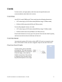
Cards ________________________________________________________________________ 71
Card Size _________________________________________________________________ 71
Card Material _____________________________________________________________ 71
Pre-Punched Cards _______________________________________________________ 71
New Cards for Color Printing _______________________________________________ 72
Adhesive-Backed Cards ___________________________________________________ 72
Card Quality Guidelines ___________________________________________________ 72
Card Surface __________________________________________________________ 72
Card Handling_________________________________________________________ 73
Card Storage __________________________________________________________ 73
Replacement Parts ____________________________________________________________ 74
Printhead Cartridge _______________________________________________________ 74
Print Ribbon Cartridge _____________________________________________________ 74
Cleaning Roller Spindle ____________________________________________________ 74
Cleaning Supplies_____________________________________________________________ 75
Large Output Hopper __________________________________________________________ 75
200-Card Input Hopper ________________________________________________________ 75
Cable Lock Option ____________________________________________________________ 75
Power Supply _________________________________________________________________ 75
Cables and Power Cord _______________________________________________________ 76
Data Cables ______________________________________________________________ 76
USB Cable _____________________________________________________________ 76
Network Cable ________________________________________________________ 76
Smart Card Cable _____________________________________________________ 76
Power Cord _______________________________________________________________ 77
vii
viii
Chapter 1: Installation
This chapter describes system requirements and provides setup instructions for the Datacard® SD/CD™ Series Card Printers. Your installation may have additional requirements for a card production environment. Talk to your system administrator to determine the optimum location for card production.
For driver installation troubleshooting and card production troubleshooting information, refer to your printer’s Driver Guide and User’s Guide.
PC Requirements
Use a PC that meets or exceeds the following:
•
A 32‐ or 64‐bit processor, running at 2GHz or faster •
2GB or more memory (RAM) and at least 1GB free space on the hard drive •
One of the following supported operating systems: •
Windows 8, 32‐ or 64‐bit
•
Windows 7, 32‐ or 64‐bit
•
Windows XP, 32‐bit, Service Pack 3 •
Windows Server 2012 •
Windows Server 2008 , 64‐bit
•
Windows Server 2003 , 32‐bit
•
USB 2.0 port or Ethernet network connection
•
ID software or other card production software to capture and organize the data to appear on each card SD/CD Installation and Administrator’s Guide
1
Network Requirements
You can connect many network printers to one PC. The maximum number of printers depends on the capacity of the network to deliver data to the printer. To install a printer on a network, the following components are required: •
An Ethernet network that uses the TCP/IP protocol and can run at 100 megabits per second, also called 100base‐T. Printers also support 10base‐T. •
An Ethernet cable to connect the printer to the network. An Ethernet cable is not supplied with the printer. •
A PC that meets the “PC Requirements” described on page 1, and is connected to and communicating with the network. USB Requirements
You can connect up to eight card printers to a PC using USB cables.
To install a printer using a USB connection, the following components are required: •
A high‐speed USB port. USB 2.0 is required.
•
A USB cable to connect the printer to the PC. A USB cable is supplied with the printer. •
A PC that meets the “PC Requirements” described on page 1. If you need to connect two card printers to a PC with one USB port, use a single, independently powered USB hub to which you can connect both printers. 2
Installation
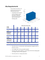
Site Requirements
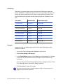
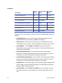
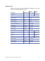
Set up and use the printer in an environment that meets the following requirements. •
Provide space for the printer and for clearance around the printer. The printer dimensions and clearance area are shown in the following table.
Dimensions (inches/mm)
Printer
Model
A
B
C
D
E
F
G
SD260
10.00
254
8.80
224
4.00
102
6.85
174
4.00
102
15.37
390
4.00
102
10.00
254
8.80
224
4.00
102
6.85
174
4.00
102
21.21
539
4.00
102
10.00
254
8.80
224
4.00
102
6.85
174
4.00
102
21.21
539
4.00
102
N/A
14.5
369
8.00
203
16.5
419
15
381
27.5
699
4.00
102
SD260L and
SD360 with
Smart Card
CD800
CD800 with
optional multicard hopper
Options such as a large output stacker and 200-card input hopper add height to the
printer. Additional clearance is required when using these options.
•
Place the printer in an environment with temperatures ranging from 60° to 95°F (15° to 35°C). •
Use a single‐phase, 3‐wire, grounded receptacle. •
Place the system and its supplies in a clean office environment, keeping paper and foreign materials off the equipment.
•
Place the printer on a sturdy, level surface. SD/CD Installation and Administrator’s Guide
3
•
Place the printer away from direct sunlight. •
Do not place the printer near heating ducts, fans, or other air vents. •
Do not use the printer for purposes other than the intended use. Electrical Requirements
The ENERGY STAR®‐rated power supply detects the input voltage and works within the range stated.
Printer Model
CD800
SD360
Electrical Requirements
110-240V/50-60 Hz/3.0 Amp
The printer is ENERGY STAR‐qualified only when used with the included power supply. Secure Printing Requirements
Secure printing consists of encrypting print commands and card data and transmitting the information securely from the PC to the printer. To use encryption, your printer must support secure printing. Printers that support secure printing are shipped with secure printing enabled. Refer to “Behavior ” on page 42 for more information on using the Printer Manager web service to specify printer security settings.
When you use the XPS Card Printer Driver, the driver uses the most secure printing protocol enabled in the printer. For more information, refer to your card printer’s Driver Guide. If your card production site requires secure printing, use the following:
•
Datacard SD260L, SD360, or CD800 card printers with secure printing enabled
The SD260 and earlier models of SD and CD printers do not support secure printing and handle only non‐secure printing. You can install a mix of secure and non‐secure printers, but make sure to connect and install each secure printer to the appropriate host PC during installation.
4
•
A PC that meets the PC requirements cited earlier in this section
•
Ethernet and USB connections that meet the requirements •
Internet Explorer Version 5.5 or newer installed on the PC
Installation
Set Up the Printer
This section provides information about setting up the printer to print cards.
Setup includes the following:
•
Prepare the Printer
•
Install Optional Equipment on page 10
•
Use the Card Printer Driver on page 13 or Use OpenCard Data Format on page 13
Prepare the Printer
To prepare the printer to print cards, remove any packing material, load blank card stock into the input hopper (optional), load print ribbon, and load a cleaning sleeve onto the print cartridge. Remove Packing Material from the Printer
Required only on printers with the optional multi‐card hopper.
1. Unlock the printer and open the printer supplies access door.
2. Remove the packing material inserted behind the multi‐card hopper.
3. Close the printer supplies access door.
SD/CD Installation and Administrator’s Guide
5
Load Cards
Single Hopper
If you are using a manual feed printer, skip this step and keep a supply of blank cards close to the printer. For printers with an input hopper, do the following:
1. Open the input hopper.
2. Load the cards into the input hopper. (Fan the cards before placing them in the hopper—
optional.)
•
Insert magnetic stripe cards with the stripe down and toward the right side of the input hopper. •
Insert smart cards with the smart card chip on top toward the back of the hopper.
3. Close the input hopper.
6
Installation
Optional Multi-Card Hopper
1. Unlock the printer and open the multi‐card hopper.
2. Load the cards into the hoppers. The input hoppers are labeled H1 through H6. You can load up to 100 cards into each hopper. (Fan the cards before placing them in the hoppers—optional.) •
Insert magnetic stripe cards with the stripe down and toward the right side of the input hopper. •
Insert smart cards with the smart card chip on top toward the back of the hopper.
3. Close the multi‐card hopper and lock the printer when you finish loading cards.
SD/CD Installation and Administrator’s Guide
7
Load Print Ribbon
Load the ribbon when you install the printer and when the ribbon runs out. 1. Unlock the printer and open the printer supplies access door on the optional multi‐card hopper.
2. Open the printer cover.
3. Remove the print ribbon cartridge. 4. Load a full roll of print ribbon onto the spindle closest to the cartridge handle. 5. Place the empty spool on the spindle with the black gear. 6. Wind the empty spool counterclockwise one full turn. 8
Installation
Load the Cleaning Sleeve
Load a new cleaning sleeve with each new roll of print ribbon.
The printer ships with the cleaning roller spindle installed on the print ribbon cartridge.
1. Remove the cleaning roller spindle from the ribbon cartridge and slide the spindle into the continuous cleaning sleeve (a). 2. Place the spindle with cleaning sleeve onto the ribbon cartridge (b). 3. Remove the protective wrapper from the cleaning sleeve (c). Install the Ribbon Cartridge
Install the assembled print ribbon cartridge into the printer.
1. Open the printer cover.
2. Hold the print ribbon cartridge by the handle and lower it into the printer with the handle toward the front of the printer.
3. Make sure that the ribbon cartridge is correctly positioned in the guides. 4. Close the printer cover (and the supplies access door on the optional multi‐
card hopper). Lock the printer, if necessary. SD/CD Installation and Administrator’s Guide
9
Install Optional Equipment
You can install additional equipment on the printer depending on your requirements.
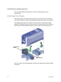
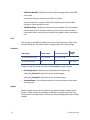
Install a Large Output Hopper
The output hopper included with the printer holds about 25 cards. The printer also can be used with an optional large output hopper that holds up to 100 cards. The large output hopper kit includes two base sections and the large output hopper. The two base sections are the same; turn them back to back to use them. Each base has hooks (marked by green circles) to attach it to the printer base.
Large Output
Hopper
Base Sections
You can remove the standard hopper and attach the large output hopper without using tools. 10
Installation
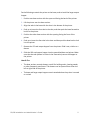
Do the following to attach the printer to the bases, and to install the larger output hopper. 1. Position one base section with the open end facing the back of the printer.
2. Lift the printer over the base section. 3. Align the tabs in the base with the slots in the bottom of the printer.
4. Push up to insert the four tabs in the slots, and then push the base forward to lock it to the printer. 5. Position the other base section with the opening facing the front of the printer.
6. Push up to insert the four tabs in the slots and then push the base back to lock it to the printer. 7. Remove the 25‐card output hopper from the printer. Slide it out, similar to a drawer. 8. Slide the 100‐card output hopper into the assembled base and printer. Make sure that the tabs (shown in circles in the illustration) secure the hopper to the printer. HINTS & TIPS
•
The base sections contain drawers, useful for holding cards, cleaning swabs, or other frequently used items. The drawers can be opened from either the left or right side of the printer.
•
The base and large output hopper remain attached when the printer is moved or carried.
SD/CD Installation and Administrator’s Guide
11
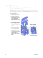
Install the 200-Card Input Hopper
The standard input hopper can hold about 100 cards. Some printers can be upgraded to use a 200‐card input hopper. The 200‐card input hopper kit includes the larger hopper with an attached cover. The standard hopper is easily removed and the 200‐card hopper can be installed without using tools. 1. Open the input hopper. 2. Press the release tab located on the back wall of the hopper while lifting the hopper up and off the printer. 3. Install the 200‐card input hopper by aligning the tabs with the slots on the printer. Hopper release tab
4. Push the hopper down until it clicks into place.
5. Load up to 200 cards in the hopper and close the hopper cover. The printer is ready to print cards.
12
Installation
Install the Optional Cable Lock
The cable lock is a user‐installed feature that does not require special tools to install. The package contains a Kensington® lock with keys, instructions, and a metal security plate. The security plate is installed in the printer and is designed to accommodate the T‐bar of the Kensington lock.
1. Prepare the printer by installing the metal security plate: A. Tip the printer on its right side.
B. Locate the security plate receptacle on the underside of the printer toward the back left side.
C. Insert the security plate into the receptacle with the open end toward the printer.
2. Follow the instructions included with the lock to complete the installation.
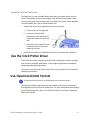
Use the Card Printer Driver
The Card Printer Driver uses Microsoft XPS print technology to support printing from currently available applications. It also supports applications developed using supported operating systems. If you plan to use the Card Printer Driver, refer to your printer’s Driver Guide for complete information.
Use OpenCard Data Format
The OpenCard Data Format is not supported by the Card Printer Driver.
The OpenCard Data Format option can be enabled at the factory or through a field upgrade on an SD/CD series card printer. For more information about setting up the OpenCard option, refer to the SD and CD Series Card Printers OpenCard Data Format Guide.
SD/CD Installation and Administrator’s Guide
13
14
Installation
Chapter 2: Elements of Card
Design
Card design is the name given to the combined features of the processed cards.
This chapter provides helpful information about card design, including:
•
Basic Card Design on page 15
•
Printing Design on page 16
•
Magnetic Stripe Design on page 27
•
Smart Card Design on page 30
•
Settings for Card Design in Printer Manager on page 31
Basic Card Design
Card design includes:
•
Optional color printing, if available.
•
The various types of data, such as name and account number, and special features such as magnetic stripe or smart card chip.
•
The layout of the data.
SD/CD Installation and Administrator’s Guide
15
Printing Design
Color Printing
Color print ribbon is available in full‐panel and short‐panel styles. Full-Panel Ribbon
Full‐panel color printing uses a print ribbon with three color panels: Y (yellow), M (magenta), and C (cyan). The ribbon also includes a K (black) panel and a T (topcoat) panel. The printer applies the YMC color panels to the card first, prints black components using the K panel, and then applies the T (topcoat) to protect the color image from damage. Short-Panel Ribbon
Color print ribbon also is available in a short‐
panel option. The color area for short‐panel ribbon is 1.57 inches (40mm). The ymc panels of short‐panel ribbon are approximately half the length of a full card. (In this guide, “ymc” in lowercase, instead of “YMC,” refers to “short‐panel” color panels.)
When you print with short‐panel print ribbon, you define the location of the color area in the card design. Color printing begins when the software detects a color pixel and continues for the length of the ymc panels.
Split-Ribbon Color Printing
Split‐ribbon color printing lets you use fewer ribbons to print cards in color. It is available only with the Card Printer Driver. Refer to your printer’s Driver Guide for information on how to specify split‐ribbon color printing.
Split‐ribbon color printing uses a single ribbon panel set from a full‐color ribbon to print both sides of a card, rather than two or three panel sets. The ribbon can be a full‐panel or short‐panel color ribbon. The order in which the color, black, and topcoat sections of the panel set are used to print the card depends on the type of ribbon installed in the printer and the split‐ribbon option selected on the driver Printing Preferences window. Most types of cards, including cards with magnetic stripes and smart cards, can be printed using split‐ribbon printing. Options for color, monochrome, and topcoating are available when you use split‐ribbon printing.
16
Elements of Card Design
Manage Color
Color management is the process of making color on the PC monitor and printed card appear as similar as possible. For color management, the card printer uses the sRGB color standard (standard Red, Green, and Blue color space).
Print Text in Color
The printer can print text in any color. Small characters are likely to be more readable if they are formatted as black and printed with the black (K) panel. The printer supports 6‐point or larger text with a sans‐serif font.
Print Graphics in Color
The printer produces full‐color images from most types of graphics. It can use BMP, JPEG, TIFF, and PNG file formats for photos and logos. Vector graphics, such as WMF and SVG files, have components such as shapes with lines and fills. Components defined as black in the file normally print with the K panel. Because the printer uses the print ribbon panels in sequence (YMC first, then K), black images can print over color graphics. For the best appearance of color graphics, or to prevent backgrounds that are black from printing over colored images, use a color that appears black but is not, so that all parts of an image print with the YMC panels. For example, in the RGB color space, 0, 0, 0 is black (and prints with the K panel), but 0, 0, 5 is not black (and prints with the YMC panels). Types of Color Images
Cards can include both color photos and a color logo or text. The logo is usually the same on each card, and the photo is unique. Follow these guidelines to obtain the best results for printing both logo and photos.
•
First, check the color quality of the photos:
•
Adjust the image capture system to get the best quality photos; work with distance, lighting, and camera settings to obtain consistent, high‐quality photos.
•
Evaluate the quality of printed photos after the image capture system is optimized.
SD/CD Installation and Administrator’s Guide
17
•
Next, evaluate the other color areas of the card, such as text or logo:
•
Check your card production application for settings that can help improve the printed color of text.
•
Use image editing applications (such as Adobe® Photoshop®) to change the color of a logo file for optimal printing.
•
Contact your service provider for assistance if the cards do not have the colors you want.
Monochrome Printing
Monochrome Printing with Full-Color Ribbon
Full‐color print ribbon includes a black panel. The black panel transfers to the card differently than the YMC panels. Text and bar codes are usually printed with the black panel. Full‐color print ribbon also prints any monochrome or one‐bit‐per‐pixel graphics using the K panel.
Monochrome Ribbon
Monochrome ribbon produces single‐color cards. Monochrome ribbon can be any of the following: •
Alternating black and topcoat panels (KT or KTT ribbon) The printer applies black and one or two topcoat panels on the same side of the card. •
Continuous black (K ribbon)
•
A continuous color, such as green or silver (also K ribbon) Continuous monochrome printing with Datacard‐certified ribbon uses the Ribbon Saver feature. With Ribbon Saver, the printer begins using ribbon at a location that corresponds to the leading edge of the card. The printer continues to spool ribbon for the length of the image but no farther. The printer leaves a small margin between each card to avoid image overlap.
18
Elements of Card Design
Print Text in Monochrome
Printing text using a K panel can make text look crisp, because it uses only one panel for printing. Fine text is more readable when printed with more power. You set the power using the Printer Manager. Refer to “Printer Setting Menu” on page 38 for more information.
The font used also affects legibility. The printer reliably prints 6‐point Arial font. Bold, sans‐serif fonts are more readable after printing than serif fonts, or fonts with thin strokes, as shown at right. In the example, fonts that print well are shown toward the top of the card.
Print Bar Codes
Bar code design follows a set of standards based on the type of bar code produced. Bar codes contain a series of black lines (bars) separated by white areas (spaces). Each character of encoded data is represented by a set of bars and spaces. A bar code standard specifies how many bars and spaces encode a character. The standard also specifies the minimum size of the white area, or quiet zone, that surrounds the bar code.
When an application prints bar codes, the data is sent to the printer as an image. The format in which the application sends the image determines how the image is rendered. If the data sent is a one‐bit‐per‐pixel image, such as pure black bars on a white background, the software processes it using the K panel of the print ribbon. If the data contains a pixel of color other than pure black or pure white, such as the various colors in a JPEG image, it processes the image using the YMC panels of the print ribbon. SD/CD Installation and Administrator’s Guide
19
Bar Code Guidelines
Bar codes print more successfully when you observe the following guidelines.
Bar Code Placement
•
Maintain the required quiet zone around the actual bar code, as shown in the illustration. •
Locate bar codes at least 0.25 inch (6.3mm) from other printing and from the edge of the card.
•
For best results, orient the card so the bars are parallel to the long edges of the card, as shown. This orientation most accurately prints readable bar codes.
Bar Code Size
•
A lower density bar code is easier to read, because the bars are wider and spaced farther apart. •
The width of the narrow elements in the bar code must be large enough to be read consistently. The capabilities of the bar code reader might influence this.
•
The bar code must be tall enough to be read under normal conditions.
Bar Code Print Settings
20
•
To achieve the best quality printing and improve the readability of the bar code, use the K (black) panel of color print ribbon to print the black bars. Bar codes printed with YMC panels are not as crisp and sharp as those printed with K only. •
Infrared readers require that the K panel be used to print the bar code. •
Bar codes are usually more readable when they are printed with less power.
•
The ANSI standard for bar code quality (X3.182) assigns a grade to a bar code to indicate its readability. Choose a K power value and bar code size to produce the grade your system requires. Refer to “Printer Setting Menu” on page 38 for information on setting the K power value.
Elements of Card Design
Test Bar Codes
Always test the readability of bar codes under production conditions. Factors to consider include:
•
If you print cards one at a time, print the samples using that method. If you print cards in batch (many cards sent to the printer at the same time), use a production‐sized batch and evaluate cards from the beginning, middle, and end of the batch.
•
Use exactly the same cardstock for testing that you use for production. The cardstock can affect the readability of bar codes. Usually, a white surface that reflects light in many directions is needed. Test cards before purchasing production quantities.
•
Include other card design components that you use in production, such as topcoat.
•
Use the same bar code readers as users have, and test each card multiple times to simulate any wear the card might experience. Also test multiple cards.
Card Design Changes That Affect Bar Codes
If you make substantial changes to the way you produce cards, review setup tasks to make sure that cards continue to have the quality you require. Substantial changes that can affect bar codes include: •
Changing from batch processing to issuing single cards (or changing from issuing single cards to batch processing). Check for differences in K printing and full‐color printing.
•
Purchasing a new brand of unprinted cards, which can change the color of some images.
•
Changing to or from preprinted cards, which can change the color of some images. •
Moving the card printer to a new location, where environmental changes such as amount of light or relative humidity can affect images, supplies, or printer operation. If you change the design of your cards, or if you start producing an additional card design, review setup tasks to make sure that each design prints as required. Test new card designs as described in this guide. You might identify changes to your process to support production of more than one design. SD/CD Installation and Administrator’s Guide
21
Printing Bar Codes with the Card Printer Driver
If you use the Card Printer Driver, you can use the driver’s Printing Preferences window to specify a setting to detect bar codes embedded in an image and print the image using the K (black) panel of a color print ribbon. When the preference is enabled, the printer detects the 1‐D, 2‐D, and Postal bar code types shown in the following table. Refer to the printer’s Driver Guide for information on specifying this setting.
1-D Bar Codes:
22
Postal Bar Codes:
•
Code 11
•
PostNet
•
Code 39
•
Planet
•
Code 39 Extended
•
RM4SCC
•
Code 93
•
AustraliaPost
•
Code 128
•
IntelligentMail
•
2of5 Interleaved
•
Codabar
2-D Bar Codes:
•
Patch Code
•
PDF417
•
EAN 8
•
Data Matrix
•
EAN 13
•
QR Code
•
UPC A
•
Micro QR Code
•
UPC E
•
Add 2
•
Add 5
Elements of Card Design
Apply Topcoat
Full‐color printing fades if it lacks topcoat protection. Topcoat protects the printed image on the card. It is applied as an even, consistent film.
Make sure that all color printing is covered with topcoat (except for areas such as magnetic stripe, smart card chip, or signature panel).
When a ribbon with a topcoat or “T” panel is installed, the printer can apply topcoat to the card using the printhead. Full‐color (YMCKT), KT, and KTT ribbons include topcoat panels.
Topcoat must be requested by the application sending the card to the printer. Most card production software requests topcoat automatically.
Do not apply topcoat over the magnetic stripe, smart card chip, or signature panel of a card. To prevent topcoat application, you must define a non‐printing area.
Non-Printing Areas
The card design can have areas where printing is not allowed. Such areas include a magnetic stripe, signature panel, or smart card chip. Card production software usually manages such non‐printing areas automatically. If you do not use ID software, you can use the dimensions provided below for magnetic stripe and smart card non‐printing areas to customize your print and topcoat areas.
• Blocking for non‐printing areas typically extends 0.1 inch beyond the edges of a feature. The dimensions listed in the following sections include the extended blocking region.
• Print several cards using your card design and application to verify that printing and topcoat are applied as you intend.
SD/CD Installation and Administrator’s Guide
23
Standard Magnetic Stripe Non-Printing Area
The 3‐track magnetic stripe typically is on the back of the card, while the single‐
track magnetic stripe is usually on the front of the card. The green arrow shows the direction the card travels through the printer. Use the following dimensions to prevent printing in the magnetic stripe area.
A
B
C
3-track
3.37 in
85.6mm
1.46 in
37.1mm
0.66 in
16.8mm
2-track
3.37 in
85.6mm
1.57 in
39.9mm
0.55 in
14mm
Single-track (JIS)
3.37 in
85.6mm
1.60 in
40.6mm
0.52 in
13.2mm
Standard Smart Card Non-Printing Area
The smart card area typically is on the front of the card. The green arrow shows the direction the card travels through the printer. Use the following dimensions to prevent printing in the smart card area.
A
0.88 in
22.4mm
B
C
D
1.17 in
29.8mm
0.88 in
22.4mm
1.47 in
37.3mm
Custom Non-Printing Areas
Use ID software, a custom application, or escape codes to define custom non‐
printing areas for one or more of the following:
24
•
Blocking printing but not topcoat
•
Non‐standard areas, such as a pre‐printed logo or a signature panel
•
More than one area on the same side of the card
Elements of Card Design
Card Layout
The arrangement or layout of components determines how well your card design works for users. Follow these guidelines to position card design components for best results.
Margins
Any unprinted area at the edge of the card or around the perimeter of a card feature is called the margin. Margins at the Edge of a Card
Some card printers can print edge to edge, which is the same as a margin of zero (0) or no margin. The card on the left shows a margin of white space at the outer edge of the card. The card on the right shows edge‐to‐edge printing.
•
Edge‐to‐edge printing can require fine‐tuning the printer and the card design. Include this task as part of setup.
•
Some contactless cards support edge‐to‐edge printing. Contact your card manufacturer to learn whether the cards you use support edge‐to‐edge printing.
Margins for Card Features
Maintain a margin between printing and card features, such as a signature panel, magnetic stripe, or smart card chip. For best results, do not print closer than 0.1 inch (2.5mm) from such a feature.
SD/CD Installation and Administrator’s Guide
25
Backgrounds
Use the following suggestions to help you select a background for a professional‐
looking card. For best results, make sure the background design does not emphasize the location of card features, such as embedded electronics.
•
Consider using a white background for the card to achieve consistent professional results.
•
Consider using smaller blocks of color, patterned areas, or gradients to highlight printed card features such as a name, photo, or logo.
•
Avoid using a solid‐color background or halftone over a large area of the card. It can show flaws on the card (such as an uneven surface) or the location of card features (such as a smart card chip).
•
Avoid halftones, especially gray, which can highlight the location of card features and flaws.
Image Placement
Use the following suggestions to help you locate important images, such as a photo, logo, or bar code. When placing images, avoid uneven areas and areas of high wear, which can result in inconsistent print quality.
26
•
Do not place an important image on the front of the card in the same area as a magnetic stripe or other machine‐readable feature. Frequent use of a card in a reader can wear away the image on the opposite side of the card.
•
Do not place an important image directly on the other side of a signature panel. Residue from the panel can cause printing problems on an adjacent card. Place the image above, below, or to the side of the panel.
•
Do not place an important image directly on the other side of a smart card chip. The card might not be as flat in that area, and printing voids can occur.
Elements of Card Design
Magnetic Stripe Design
The printer contains a magnetic stripe module to process magnetic stripe data. There are two magnetic stripe configuration options: ISO and JIS. Use the Printer Configuration Label (described in the printer’s User’s Guide) to determine the type of module installed. Magnetic Stripe Data Formats
The module format (ISO or JIS) defines the type and format of the information to encode. The standard ISO format (also known as IAT) is a three‐track option. The JIS format is a single‐track option. Both formats include default data settings that determine how many characters can be encoded on each track, and which characters can be encoded.
Your cards can use the default format for each track, or can use a different combination of tracks and data formats.
Three-Track Option (ISO/IAT)
The default data formats for a three‐track magnetic stripe option are:
•
Track 1 — IATA •
Track 2 — ABA •
Track 3 — TTS This combination is often abbreviated IAT. This format is also called ISO format.
IATA (International Air Transport Association)
The maximum number of characters for IATA format data is 76 characters. These characters can include spaces, uppercase alphabetic characters, numeric characters, and the following special characters:
! # $ % ' ( ) * + , ‐ . / ; : < @ > = ^ ] \ [ " & _
ABA (American Bankers Association)
The maximum number of characters for ABA format is 37 characters. Numeric characters and the following special characters are allowed:
: ; < = >
SD/CD Installation and Administrator’s Guide
27
TTS (Thrift Third Standard)
The maximum number of characters for TTS format is 104 characters. Numeric characters and the following special characters are allowed: : ; < = >
Single-Track Option (JIS)
The default data format for a single‐track magnetic stripe module is the JIS (Japanese Industrial Standard) Type II format.
The maximum number of characters for the JIS format is 69 characters. These characters can include spaces, numeric characters, uppercase alphabetic characters, lowercase alphabetic characters, and the following special characters:
! " # $ % & ' ( ) * + , ‐ . / : ; < = > ? @ [ ] ^ _ ~ { | } ~
Japanese‐language characters also are supported from a PC running a Japanese edition of a supported operating system. They include the following:
28
•
Special characters: •
45 Katakana characters:
•
10 Katakana characters: Elements of Card Design
Each time you start using Japanese‐language characters, or stop using them, it adds a hidden character. Each hidden character reduces the number of characters you can encode by one character.
Magnetic Stripe Coercivity
The printer may require additional settings to match the coercivity of the card. Once these values are set they remain the same for all cards processed using the same design. The defaults are set to standard ISO format and high coercivity. Refer to “MagStripeGeneral” on page 51 for information on changing the coercivity.
The type of magnetic stripe cards you use must match the type of module installed. Three high‐coercivity cards are included with the system. Use these cards to make sure the printer is encoding magnetic stripe information properly. Purchase additional magnetic stripe cards to match the type of module you are using.
SD/CD Installation and Administrator’s Guide
29
Smart Card Design
Smart card processing differs from other types of card personalization. The “smart card” step of personalization is controlled by an application that is separate from the rest of card personalization.
Smart card setup usually is provided by a value‐added reseller or service provider. Request information about the smart card module installed and the type of cards to use from your service provider or value‐added reseller. Refer to “Smart Card Processing Requirements” on page 31 for more information.
Smart Card Codes on the Printer Label
The configuration label includes codes that identify the type and model of the smart card module installed in the printer. The following table lists the codes used on the configuration label.
Code on Label
Type of Smart Card Module
S1
Integrator Contactless
S2
SCM Dual Interface Reader
S3
HID PcProx Contactless
S4
iClass Read Contactless
S5
iClass Read/Write Contactless
S6
Duali Standard
S7
Duali Single Wire
S8
Duali Single Wire Sony Felica
The S1 value on the configuration label indicates that the printer has the basic smart card components installed. Basic components include the mounting hardware only. An integrator must install a contactless reader.
If the S2 value is included in the configuration code, the printer has the basic components of an S1, plus the SCM Dual (Contact/Contactless) Interface installed.
30
Elements of Card Design
Single-Wire Smart Card
In daily use, single‐wire smart card processing operates just like regular smart card processing. The difference in single‐wire smart card processing is in the use of a single‐wire connection with the printer rather than two. In particular, the single‐wire smart card processing allows a single USB or Ethernet connection to carry data for both smart card personalization and printing. The single‐wire smart card feature is available to an application through the Card Printer Driver Software Development Kit (SDK).
The single‐wire smart card programming interface is similar, but not identical, to the PC‐SC standard. Applications using PC‐SC to personalize smart cards require modification to use the single‐wire smart card interface.
Required components for single‐wire smart card are the same as for other smart card systems except as noted.
Smart Card Processing Requirements
The following items are required to personalize smart cards:
•
A direct local connection between the printer and the PC.
•
A smart card reader in the printer.
•
If needed, a smart card cable for the smart card port used. This cable is not needed for single‐wire processing. •
A card application that is customized to work with the printer and the smart card application (using the SDK or card production application with a smart card application manager).
•
Smart cards that work with the reader in the printer.
Settings for Card Design in Printer Manager
The Printer Manager contains card design settings that managers and service providers can use to set up card production. The card design settings include magnetic stripe setup and smart card testing. The Printer Manager also contains troubleshooting features such as a log file that can track all processes of a card job. Service providers can use the information in the log file to troubleshoot and relay information when troubleshooting card processing issues. Refer to “Printer Manager” on page 33 for more information.
SD/CD Installation and Administrator’s Guide
31
32
Elements of Card Design
Chapter 3: Printer Manager
This section describes Printer Manager, the Datacard web service available to users, administrators, and Datacard service providers.
Printer Manager
Printer Manager is a web service that displays information about the printer. System administrators or service providers can use the Printer Manager to fine‐
tune card appearance, set advanced options, and troubleshoot printing problems. Access the Printer Manager using an Internet browser and the IP address of the printer. The Printer Manager includes user access levels that control the type of information that can be viewed. You can choose from three user access levels to perform a variety of basic and advanced tasks: WebUser, WebAdmin, and WebService. Access the Printer Manager
The initial Printer Manager screen allows users to log in with a user name and password that determine their user access level. The user access level determines which menu items, options, and adjustments are available.
1. Make sure that the printer's LCD panel displays Ready.
2. Access the Printer Manager in one of two ways:
•
If you are using the Card Printer Driver, open the Printer Properties window and select the Printer Status tab.
•
Click Configure Printer to launch the Printer Manager in your default browser.
OR
•
Obtain the printer network IP address and write it down. Refer to the printer’s installation instructions for detailed procedures.
•
Open a web browser on the PC.
SD/CD Installation and Administrator’s Guide
33
•
In the Address area of the browser, enter the following:
https://printer IP address For example: https://123.1.23.123 where 123.1.23.123 is replaced by the printer IP address.
Because you are using “https” (secure protocol) to access the Printer Manager, the browser issues a warning that there is a problem with the website’s security certificate. Continue to the Printer Manager website by accepting any warning prompts.
3. The Printer Manager screen displays.
4. Select the language in which to display the Printer Manager session from the Select Language column.
5. In the Please Log In section, select a Username that matches your job responsibility and enter a password (if required). Refer to “Printer Manager User Access Levels” on page 35 for a description of the user access levels.
6. Click Log In to display the Printer Manager main screen.
34
Printer Manager
HINTS & TIPS
•
If the browser cannot connect to the printer, make sure that Ready displays on the LCD panel of the printer.
•
Some pages of the Printer Manager contain a hover‐text feature that displays help information when the cursor hovers over the setting in the description column.
•
If you change any settings in the Printer Manager, click Restore Default on the option pages to return to the default.
Printer Manager User Access Levels
The Username field controls the level of access to information and settings that correspond to the user’s job responsibility.
WebUser
WebUser access allows users to view information and change a limited amount of values. The WebUser access level is typically used by the person responsible for printing cards. Other responsibilities can include cleaning the printer, ordering printer supplies, or printing a daily or weekly log of card production. The WebUser access level displays four menu selections: Status, Printer Setting, Maintenance, and Log Out. WebAdmin
WebAdmin access allows an administrator to set up a test card and make minor adjustments to the printer. The WebAdmin user has access to configuration options and the use of diagnostics tools for troubleshooting. The WebAdmin user also can specify a password (using the Printer Settings > Update Password option) for WebUser access‐level users.
In a card production environment, the WebAdmin access‐level user typically sets up the card design, verifies communication with external data sources, and tracks printer activity and performance. WebService
WebService access has all of the above adjustments with additional access to adjust offsets.
The WebService user is typically a Datacard‐trained service provider.
SD/CD Installation and Administrator’s Guide
35
Print a Printer Manager Page
Use your Internet browser Print option to print the information from any Printer Manager page to a paper printer. •
Select File > Print from your Internet browser’s main menu. •
If the printed page does not display all the information from the Printer Manager, select File > Print Preview in your Internet browser to scale the image to fit the paper.
Use the Printer Manager
The following sections describe how to use the options on the Printer Manager menus that are available to WebUser and WebAdmin access‐level users. For information on settings available to the WebService access level, contact your service provider.
The options available in the Printer Manager are determined by the type of printer and the options installed on the printer. Not all options described in the following sections are available for all printers.
36
Printer Manager
Status Menu
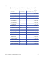
The Status menu contains information about the printer and its usage statistics. Users at all access levels can view or print Vital Product Data (VPD), Printer Status, Supplies information, Audit Data, and About Printer Manager information. Status Menu Option
Function
WebUser
WebAdmin
VPD
Display the manufacturer and
model of the card printer, a list of
the installed options, serial
numbers, and version numbers.
Print this page for reference if you
need to contact your service
provider.
View
View
Printer Status
Display the mode that the printer
is in, the printer state, how long
the printer has been powered on
(in seconds), current conditions,
and job status.
View
View
Supplies
Display information about the
print ribbon currently installed in
the printer. This includes the
ribbon part number and serial
number, additional codes that
define the ribbon, and the
percent of ribbon remaining in
relation to a new full roll of
ribbon.
View
View
Audit Data
Display card counts (both
resettable and non-resettable
counts) and error reporting
collected by the printer. This
page acts as a general overview
for all the counters and can be
useful to track card production
activity and problem history.
View
View
About Printer Manager
Display the versions and build
dates of the Printer Manager.
View
View
SD/CD Installation and Administrator’s Guide
37
Printer Setting Menu
Printer Setting Menu
Option
Function
WebUser
WebAdmin
Communication
Set or view the address
mode type and enter IP
address, subnet mask, and
gateway address
information.
No
Change Current
Values
ActivityLog
Set values in the activity
log to help isolate card
production issues.
No
Change all
Current Values
Behavior
Display printer operation
and control methods.
Only
RibbonInitialize
Change all
Current Values
VitalProductData
Display information for
WebService access level
users only.
No
No
FrontPanel
Set front panel values for
the printer.
Change
Backlight
Brightness,
KeySenseLevel
and
SpeakerEnabled
Values
Change all
Current Values
Print
Set print parameters for
color management, print
intensity, and registration
settings.
No
Change all
Current Values
Pick
Display and set pick
values. Available to
WebService access level
users only.
No
No
Transport
Set the eject speed of the
hopper and the transport
motor speed.
View only
TransMedSpeed
View only
TransMedSpeed;
Change
EjectHopper
Speed
Flipper
Set values for the duplex
module in duplex-option
printers. Available to
WebService access level
users only.
No
No
38
Printer Manager
Printer Setting Menu
Option
Function
WebUser
WebAdmin
MagStripeGeneral
Set magnetic stripe
options including
coercivity, custom
magnetic stripe formats,
and data formats.
No
Change
coercivity,
custom formats,
and data
formats
MagStripeCustomTrack1
Set customized magnetic
stripe values for track 1.
No
Change all
Current Values
MagStripeCustomTrack2
Set customized magnetic
stripe values for track 2.
No
Change all
Current Values
MagStripeCustomTrack3
Set customized magnetic
stripe values for track 3.
No
Change all
Current Values
Update Password
Set or update passwords
for the WebUser and
WebAdmin access levels.
No
Change
WebUser and
WebAdmin,
SNMP read, and
SNMP write
passwords
Set Job Queue State
Enter values for shipping
the printer to a repair
facility.
Need a password
Need a
password
SD/CD Installation and Administrator’s Guide
39
Communication
The Communication settings change the Ethernet address method from DHCP to Static. If set to Static, the IP address, subnet mask, and gateway address are entered manually to match the settings of the network.
Description
Default Value
Current Value (unit)
1) EthAddressMethod
DHCP
DHCP
2) EthDnsAddress1
0.0.0.0
0.0.0.0
3) EthDnsAddress2
0.0.0.0
0.0.0.0
5) EthGatewayAddress
0.0.0.0
0.0.0.0
6) EthIpAddress
0.0.0.0
0.0.0.0
7) EthSubnetMask
0.0.0.0
0.0.0.0
4) EthDnsSearchSuffix
•
EthAddressMethod ‐ Method used to obtain the Ethernet network IP address. Select DHCP or STATIC from the Current Value dropdown list.
•
When the value is DHCP, the EthGatewayAddress, EthIpAddress, and EthSubnetMask values are filled in automatically.
•
When the value is STATIC, the EthGatewayAddress, EthIPAddress, and EthSubnetMask values must be set manually. •
EthGatewayAddress ‐ The gateway address for the Ethernet network.
Enter the appropriate address.
•
EthIpAddress ‐ The IP address of the Ethernet network. Enter the appropriate address.
•
EthSubnetMask ‐ The subnet mask for the Ethernet network. Enter the appropriate subnet mask.
1. Click Set Current to apply the changes. 2. Log out of the Printer Manager, and then restart it for the changes to take effect. 40
Printer Manager
ActivityLog
The Activity Log menu allows you to record technical information about the printer. WebAdmin or WebService access‐level users can change settings in the activity log to help troubleshoot and isolate a card production problem. Both internal and external log values and the external log server IP address are set here.
Description
Default Value
Current Value (unit)
1) ExternalLog
Disabled
Disabled
2) ExternalLogServer
0.0.0.0
0.0.0.0
3) FilterCardActions
Notice
Notice
4) FilterConfigChanges
Notice
Notice
5) FilterJobStates
Notice
Notice
6) FilterSoapMsgs
Notice
Notice
7) FilterSystem
Notice
Notice
8) InternalLog
Enabled
Enabled
Example:
Change the Filter Job States status in the Activity Log to help isolate a card production problem. 1. Log into the Printer Manager with WebAdmin access level. 2. Select Printer Setting > Activity Log. 3. In the FilterJobStates category, select Error from the dropdown list. Changes to the state of a job, with this severity and higher, will be written to the activity log.
(You can select from the following severity options: Emergency, Alert, Critical, Error, Warning, Notice, Information, Debug, Disabled.)
4. Click Set Current to apply the changes.
We recommend operating at all Default logging settings to reduce unnecessary logging for typical printer operations.
SD/CD Installation and Administrator’s Guide
41
Behavior
Description
Default Value
Current Value (unit)
1) ActivityLogExternal
Enabled
Enabled
2) ActivityLogInternal
Enabled
Enabled
3) CPX
Enabled
Enabled
4) DPCL
Enabled
Enabled
5) DPCL2
Enabled
Enabled
6) DPCL2Secure
Enabled
Enabled
7) DPCLSecure
Enabled
Enabled
8) DPM
Enabled
Enabled
9) DPMSecure
Enabled
Enabled
10) FactoryRejectHopper
Disabled
Disabled
11) NetworkAccessControl
Disabled
Disabled
12) Plugin
Enabled
Enabled
13) RejectHopper
Enabled
Enabled
14) Remake
Enabled
Enabled
15) RemakeMethod
ConserveSupplies
ConserveSupplies
16) RibbonInitialize
Enabled
Enabled
17) SNMP
Enabled
Enabled
18) UseFactoryRejectHopper
Disabled
Disabled
19) WebServerSecure
Enabled
Enabled
42
Printer Manager
Update Current Values as needed, and then click Set Current to apply changes.
•
ActivityLogExternal ‐ Enable or disable the external activity log.
Select Enabled to allow access.
Select Disabled to block access.
•
ActivityLogInternal ‐ Enable or disable the internal activity log.
Select Enabled to allow access.
Select Disabled to block access.
•
CPX ‐ Enable or disable CPX.
Select Enabled to allow access.
Select Disabled to block access.
•
DPCL ‐ Allow DPCL commands through the unsecure port.
Select Enabled to allow access.
Select Disabled to block access.
•
DPCL2 ‐ Allow DPCL2 commands through the unsecure port.
Select Enabled to allow access.
Select Disabled to block access.
•
DPCL2Secure ‐ Allow DPCL2 commands through the secure port.
Select Enabled to allow access.
Select Disabled to block access.
•
DPCLSecure ‐ Allow DPCL commands through the secure port.
Select Enabled to allow access.
Select Disabled to block access.
SD/CD Installation and Administrator’s Guide
43
•
DPM ‐ Allow DPM commands through the unsecure port.
Select Enabled to allow access.
Select Disabled to block access.
•
DPMSecure ‐ Allow DPM commands through the secure port.
Select Enabled to allow access.
Select Disabled to block access.
•
FactoryRejectHopper ‐ Enable or disable use of the factory reject hopper.
Select Enabled to allow access (not available for duplex printers).
Select Disabled to block access.
•
NetworkAccessControl ‐ Enable or disable network access control.
Select Enabled to allow access.
Select Disabled to block access.
•
Plugin ‐ Enable or disable the plugin feature for the printer to access installed plug ins.
Select Enabled to allow access.
Select Disabled to block access.
•
RejectHopper ‐ Enable or disable use of the reject hopper for rejected cards.
Select Enabled to allow access.
Select Disabled to block access.
•
Remake ‐ Enable or disable card remakes. If Remake is enabled and a print request fails, the print request is tried again with a new card. A card is retried only once.
Select Enabled to allow.
Select Disabled to block.
•
RemakeMethod ‐ Select the method of card remakes. This setting is ignored if Remake is set to Disabled.
Select ConserveSupplies to reprint out of queue order.
Select PreserveOrder to reprint in queue order.
44
Printer Manager
•
RibbonInitialize ‐ Enable or disable initialization of the ribbon when the printer is powered on.
Select Enabled to initialize the ribbon.
Select Disabled to not initialize the ribbon.
•
SNMP ‐ Enable or disable SNMP.
Select Enabled to allow access.
Select Disabled to block access.
•
UseFactoryRejectHopper ‐ Enable or disable use of the factory reject hopper.
Select Enabled to allow access (not available for duplex printers).
Select Disabled to block access.
•
WebServerSecure ‐ Allow access to the Printer Manager (web server) through the secure port.
Select Enabled to block access.
Select Disabled to allow access.
Caution: Do not disable the web server. If the web server is disabled, it cannot be restored. To restrict access for the WebUser or WebAdmin access levels, select Printer Settings > Update Password.
VitalProductData
Vital Product Data is service‐level information about the printer or system available for WebService access level users only. Contact your service provider for information about viewing the Vital Product Data settings.
SD/CD Installation and Administrator’s Guide
45
FrontPanel
Description
Default
Value
Current Value
(unit)
Allowable
Range
1) BacklightBrightness
100
100
[0- 100]
2) KeySenseLevel
5
5
[0 - 10]
3) LcdConfigMenu
Enabled
Enabled
4) LedCardsPickedToCleaning
1500
1500
[0-1000000]
5) LedPrintheadCyclesToCleaning
2500
2500
[0-1000000]
6) LedRibbonLow
10
10
[0-1000000]
7) SpeakerEnabled
Enabled
Enabled
Change the front panel settings as needed, and then click Set Current to apply the changes.
46
•
BacklightBrightness ‐ Set the LCD Front Panel backlight brightness at the desired level from 1 percent (dim) to 100 percent (bright).
•
KeySenseLevel ‐ Set the key sensitivity level to a comfortable level. Select from 0 (low sensitivity, almost a press) to 10 (high sensitivity, barely a touch).
•
LcdConfigMenu ‐ Select Enabled or Disabled to control display of the Configuration menu on the LCD menu system. (The Status and Maintenance menus cannot be disabled.)
•
LedCardsPickedToCleaning ‐ Set the number of cards to pick between cleaning. The card light blinks amber when the printer reaches this value. If this value is set to 0, cards between cleaning are not tracked.
•
LedPrintheadCyclesToCleaning ‐ Set the number of printhead cycles between cleaning. The card light blinks amber when the printer reaches this value. If this value is set to 0, cycles between cleaning are not tracked.
•
LedRibbonLow ‐ Set the percentage of ribbon remaining before being notified that the ribbon is low and should be changed. The ribbon light blinks amber when the ribbon reaches this value.
•
SpeakerEnabled ‐ Select Enabled or Disabled to turn the speaker on or off. The speaker provides a sound in addition to the front panel lights and LCD text.
Printer Manager
Print
The Print selections provide a WebAdmin access‐level user with the ability to fine‐tune the print intensity, topcoat power, and K (black) power settings.
Description
Default Value
Allowed
Current Value (unit) Range
1) CardRegistration
0
0
2) ColorManagement
sRGBColorSpace
sRGBColorSpace
3) KPower
0
0
[-100 – 100]
4) KPower1200DPI
0
0
[-100 – 100]
5) KPower600DPI
0
0
[-100 – 100]
6) KPowerDuplex
0
0
[-100 – 100]
7) KWhiteShade
0
0
[-100 – 100]
8) LeadTrim
0.254
0.254
[0 – 5.08]
9) SettingsGroupPurpose
Print
Print 10) TPower
0
0
[-100 - 100]
11) TPowerDuplex
0
0
[-100 - 100]
12) TrailTrim
1.27
1.27
[0 - 5.08]
13) TWhiteShade
0
0
[-100 - 100]
14) YMCPower
0
0
[-100 - 100]
15) YMCPower600
0
0
[-100 - 100]
16) YMCPowerDuplex
0
0
[-100 - 100]
17) YMCPowerNosRGB
-48
-48
[-100 - 100]
18) YMCWhiteShade
0
0
[-100 - 100]
SD/CD Installation and Administrator’s Guide
[-0.5 – 50.8]
47
Change settings as needed, and then click Set Current to apply changes.
•
Card Registration ‐ Set the starting location of the printed area. The values are in mm.
Increase the value to move printing closer to the card’s leading edge. Decrease the value to move printing away from the card’s leading edge. •
ColorManagement ‐ Select None from the dropdown list to disable color management in the printer and allow color management to be handled by the application. Select sRGBColorSpace for the standard Red, Green, and Blue color space. Select MatchSP to use the color management technology of card printers.
•
KPower ‐ Modify the print intensity for K (single color) panel or K (single color) ribbon.
Increase the value to make single‐color printing more defined on the card.
Decrease the value for crisp bar codes or to prevent frequent ribbon breaks when printing with the K panel.
•
KPower1200DPI ‐ Modify the print intensity of 1200 dpi for the K panel or K ribbons.
Increase this value to make single‐color printing more defined on the card.
Decrease the value for crisp bar codes or to prevent frequent ribbon breaks when printing with the K panel.
•
KPowerDuplex ‐ Modify the print intensity for the back side K panel and K ribbons.
Increase the value to make single‐color printing more defined on the card.
Decrease the value for crisp bar codes or to prevent frequent ribbon breaks when printing with the K panel.
48
•
KWhiteShade ‐ Modify the amount of power applied to the printhead to reduce ribbon friction without transferring material. Decrease the value if material transfers to the card when it should not.
•
LeadTrim ‐ Modify the number of millimeters to remove from the leading edge of a full‐size image to keep it within the print area (1 millimeter equals 0.0394 inches or about 11.8 dot rows).
Printer Manager
•
SettingsGroupPurpose ‐ State the purpose of the settings group. Group names are not changeable. Use this option to identify the reason for creating a settings group.
•
TPower ‐ Modify the intensity of the T (topcoat) ribbon panel.
Increase the value to make printed topcoat thicker or more uniform.
Decrease the value to prevent frequent ribbon breaks while printing the topcoat.
•
TPowerDuplex ‐ Modify the intensity of the back side T (topcoat) ribbon panel.
Increase the value to make printed topcoat thicker or more uniform.
Decrease the value to prevent ribbon breaks while printing the topcoat.
•
TrailTrim ‐ Modify the number of millimeters to remove from the trailing edge of a full‐size image to keep it within the print area (1 millimeter equals 0.0394 inches or about 11.8 dot rows).
Increase the value to lengthen the printed area. Decrease the value to shorten the printed area. •
TWhiteShade ‐ Modify the amount of power applied to the printhead to reduce ribbon friction without transferring material. Decrease the value if material transfers to the card when it should not.
•
YMCPower ‐ Modify the intensity of the YMC (color) ribbon panel.
Increase the value to make the color printing more intense.
Decrease the value to reduce the color intensity or to prevent frequent ribbon breaks when printing colors.
•
YMCPower600 ‐ Modify the intensity of the 600 dpi YMC (color) ribbon panel.
Increase the value to make the color printing more intense.
Decrease the value to reduce the color intensity or to prevent frequent ribbon breaks when printing colors.
•
YMCPowerDuplex ‐ Modify the intensity of the back side YMC (color) ribbon panel.
Increase the value to make the color printing more intense.
Decrease the value to reduce the color intensity or to prevent frequent ribbon breaks when printing colors.
SD/CD Installation and Administrator’s Guide
49
•
YMCPowerNosRGB ‐ Modify the intensity when printing without the sRGB color mode.
Increase the value to make the non‐sRGB color darker
Decrease the value if using non‐sRGB color mode to prevent overly dark printing or ribbon wrinkles or tears.
•
YMCWhiteShade ‐ Modify the amount of power applied to the printhead to reduce ribbon friction without transferring material. Decrease the value if unprinted or white areas of the card have color applied to them and should not.
Pick
Pick settings are available for WebService access‐level users only. Contact your service provider for information about changing the printer’s pick settings.
Transport
Description
Default Value
Allowed
Current Value (unit) Range
1) EjectHopperSpeed
ehs_Standard
ehs_Standard
2) TransMedSpeed
800
800
[300-1800]
Change settings as needed, and then click Set Current to apply changes.
•
EjectHopperSpeed ‐ Optimize eject speed based on hopper type.
Select ehs_Standard if the printer has a standard hopper.
Select ehs_Extended if the printer has an extended hopper.
•
TransMedSpeed ‐ Set the speed at which to run the transport motor when clearing errors.
Flipper
Flipper settings are used to set values for the duplex module in duplex‐option printers. Flipper settings are available for WebService access‐level users only. Contact your service provider for information about changing the printer’s flipper settings.
50
Printer Manager
MagStripeGeneral
Magnetic stripe settings are available for WebAdmin and WebService access‐level users to set up basic magnetic stripe options.
Description
Current
Default Value Value (unit)
Allowed
Range
1) Attempts
3
3
[1 - 5]
2) Coercivity
HICO
HICO
3) DataFormat1
IATA
IATA
4) DataFormat2
ABA
ABA
5) DataFormat3
TTS
TTS
6) NoDataDisableTrack
Disabled
Disabled
7) ReadTrack1
Enabled
Enabled
8) ReadTrack2
Enabled
Enabled
9) ReadTrack3
Enabled
Enabled
10) SSA1
0
0
[-4 - 4]
11) SSA2
0
0
[-4 - 4]
12) SSA3
0
0
[-4 - 4]
13) StripeEncoderMultiplier
1.0
1
[0.9 - 1.1]
14) WriteTrack1
Enabled
Enabled
15) WriteTrack2
Enabled
Enabled
16) WriteTrack3
Enabled
Enabled
SD/CD Installation and Administrator’s Guide
51
Change settings as needed, and then click Set Current to apply changes.
•
Attempts ‐ Specify the number of attempts (automatic retries) the printer makes to encode the magnetic stripe data. This value also is used for the number of times to attempt to read magnetic stripe data
If you set this number to a lower value, it increases the throughput of the printer but can decrease the reliability of magnetic stripe encoding. If you set the number to a higher value, it decreases the throughput of the printer but can increase the reliability of magnetic stripe encoding.
A value of 1 means no retry attempts.
•
Coercivity ‐ Select the coercivity setting that matches the cards you are using. Coercivity measures the resistance of magnetic material to the removal of encoded data. High coercivity (HICO) requires more electrical force to encode data and the data is more resistant to magnetic interference. The choices are HICO, LOCO, NTT1, NTT2, NTT3. •
DataFormat (1, 2, 3) ‐ Specify the names of the data formats used for tracks 1, 2, and 3. For single‐track magnetic stripe encoding, set DataFormat1 to JIS and DataFormat2 and DataFormat3 to NONE. To use a custom data format, define the formats for tracks 1, 2, and/or 3 using the MagStripeCustomTrack (1, 2, 3) settings and then set the corresponding DataFormat settings to CUSTOM.
52
•
NoDataDisableTrack ‐ Disable the magnetic stripe write head for a track if the track contains no data. When this is disabled, any track that was not given data is erased.
•
ReadTrack (1, 2, 3) ‐ Allow magnetic stripe read actions to read from tracks 1, 2, and 3.
•
SSA (1, 2, 3) ‐ Set the start sentinel adjustment for tracks 1, 2, and 3. (SSA3 also sets the start sentinel for a single track.) The start sentinel is encoded on the magnetic stripe immediately before the first data character and indicates the beginning of data. Enter a value from ‐4 to 4.
•
StripeEncoderMultiplier ‐ Enter a multiplier value to compensate for encoder variation.
•
WriteTrack (1, 2, 3) ‐ Allow magnetic stripe write actions to write to tracks 1, 2, and 3.
Printer Manager
MagStripeCustomTrack 1 – 3
Custom magnetic stripe settings are available for WebAdmin and WebService access‐level users to define custom magnetic stripe options. Description
Default Value
Current Value
(unit)
Allowed Range
1) CustomCharHigh
Track 1: 95
Tracks 2 & 3: 63
95
63
[1 - 255]
2) CustomCharLength
Track 1: 6
Tracks 2 & 3: 4
6
4
[1 - 8]
3) CustomCharLow
Track 1: 32
Tracks 2 & 3: 48
32
48
[1 - 255]
4) CustomCharMask
Track 1: 32
Track 2: 48
32
48
[1 - 255]
5) CustomCharMax
Track 1: 76
Track 2: 37
Track 3: 104
76
37
104
[1 - 255]
6) CustomDensity
Tracks 1 & 3: 210
Track 2: 75
210
75
[1 - 255]
7) CustomEndSentinel
63
63
[1 - 255]
8) CustomLrc
EVEN
EVEN
9) CustomParity
ODD
ODD
10) CustomSdsNulls
0
0
[0 - 255]
11) CustomSdsRecords
1
1
[0 - 255]
12) CustomSdsSs
1
1
[1 - 255]
13) CustomStartSentinel
Track 1: 37
Tracks 2 & 3: 59
37
59
[1 - 255]
SD/CD Installation and Administrator’s Guide
53
Change settings as needed, and then click Set Current to apply changes.
54
•
CustomCharHigh ‐ Specify the numeric value of the highest ASCII character supported for input data on the track.
•
CustomCharLength ‐ Set the number of bits to represent one character of data on the track, also called bits per character.
•
CustomCharLow ‐ Specify the numeric value of the lowest ASCII character supported for input data on the track.
•
CustomCharMask ‐ Specify the mask value that is subtracted from the ASCII numeric value to get the encoded value.
•
CustomCharMax ‐ Specify the maximum number of data characters for the track. The value does not include the Start or End Sentinels.
•
CustomDensity ‐ Specify the number of data bits per inch of magnetic stripe media for the track, also called bits per inch or bpi. Allowed values are 75 bpi or 210 bpi.
•
CustomEndSentinel ‐ Specify the last character encoded, which identifies the end of encoded data for the track.
•
CustomLrc ‐ Specify a cumulative parity bit that is encoded after the end sentinel to provide simple error checking.
•
CustomParity ‐ Specify a character‐level parity bit encoded after each character to provide simple error checking.
•
CustomSdsNulls ‐ Specify the number of nulls between each copy of the data record. You should not change this value.
•
CustomSdsRecords ‐ Specify the number of times to encode the data record. You should not change this value.
•
CustomSdsSs ‐ Specify the number of start sentinels before each data record. You should not change this value.
•
CustomStartSentinel ‐ Specify the first character encoded, which identifies the start of the encoded data for the track.
Printer Manager
Using custom magnetic stripe data formats is a two‐step process. First, define the custom tracks using MagStripeCustomTrack1, MagStripeCustomTrack2, and/or MagStripeCustomTrack3. Second, apply the custom track using the settings on the MagStripeGeneral menu.
1. To use the defined custom track:
A. Open the MagStripeGeneral menu. B. Select Custom for DataFormat1, DataFormat2, or DataFormat3 to use the custom track. •
MagStripeCustomTrack1 corresponds to DataFormat1
•
MagStripeCustomTrack2 corresponds to DataFormat2
•
MagStripeCustomTrack3 corresponds to DataFormat3
2. Click Set Current to apply the changes.
SD/CD Installation and Administrator’s Guide
55
Update Password
WebAdmin access‐level personnel can choose to password protect the Printer Manager and limit access to the advanced settings. Adding password protection is the preferred method of restricting access to the Printer Manager. Description
Value
Choose Username to Update
WebAdmin
Current Password
New Password
Confirm New Password
1. Select the access level assigned to the Username from the drop‐down list. The WebAdmin access level can also update the WebUser, SNMP read, and SNMP write passwords.
2. Enter the current password. If the current password field is empty (no entry), leave this box blank.
3. Enter the new password in the corresponding field.
4. Enter the new password again to confirm it.
5. Click Update Password to apply the changes.
HINTS & TIPS
Passwords are hierarchical in the following order: WebService, WebAdmin, and WebUser. You can use a password that is higher in the hierarchy to log in to a specific role. 56
Printer Manager
Set Job Queue State
Enter or select values prior to shipping the printer or system to or from repair facilities. Field
Value
Description
Current Password
Enter the currently set password.
Leave the field blank if no password
was previously set.
Next Password
Enter a new password. A blank value
means that no password is required
or leaves the current password
unchanged, depending on the
settings.
Confirm Next Password
Retype the Next Password.
State
Online
StartJob succeeds if there is space in
the queue.
Suspend
StartJob succeeds if there is space in
the queue and exceptionJob=true.
Offline
StartJob does not succeed under
any circumstances.
1. Enter the current password for the printer or system.
2. Enter a new password for the printer or system.
3. Re‐enter the new password for verification.
4. Select a state:
•
Online ‐ The printer performs normally.
•
Suspend ‐ Deactivates the printer, but allows for some exception jobs.
•
Offline ‐ Deactivates the printer for transportation.
5. Click Set Job Queue State to apply the changes.
To re‐enable an “Offline” printer and set it back to “Online,” you must enter the same password that was used to set it to “Offline.”
SD/CD Installation and Administrator’s Guide
57
Troubleshooting Menu
The Troubleshooting menu for the WebAdmin access level contains settings and tools that help you isolate card production issues. Use the Troubleshooting options to print test cards, view and print the activity log, reset the log, reset counters, and reset the printer.
58
Troubleshooting Menu
Option
Function
WebUser
WebAdmin
Test Card
Print test cards
No
Change all current
values/Run card
Activity Log
Display printer
activity
No
View
Reset Log
Reset the
activity log
No
Yes
Print Request Log
Display a log of
printer requests
No
Yes (applies only to
OpenCard factoryactivated printers)
Reset Counters
Reset card
counters
No
Yes
Printer Reset
Restart the
printer
No
Yes
Printer Manager
Test Card
The Test Card menu shows the items available to WebAdmin access‐level users. Print test cards to troubleshoot card production issues. Select the options to test from the following.
Description
Card Front (page 1)
Input Hopper Number
1
Magnetic Stripe
Card Back (page 2)
[]
Color
[X]
[]
Monochrome
[]
[]
Topcoat
[]
[]
Second Topcoat
[]
[]
Test Pattern to use for Color
and/or Monochrome
[TestPattern1 ]
[TestPattern1 ]
Description
Current Value (unit)
Allowed Range
Copies
1
[1-10]
Park Smart Card
[]
SmartCard Park Time
10
Do not eject card
[]
Test Card Other Options
seconds
[0-300]
Enter the value(s) for the type of test card to print, and then click Run to send the test card to print.
•
Input Hopper Number ‐ Select the input hopper number where the card to be used is loaded.
•
Magnetic Stripe ‐ Print the test card with encoded magnetic stripe data.
•
Color ‐ Print the test card using the YMCK panels of the print ribbon on the front or back. •
Monochrome ‐ Print the test card using a monochrome ribbon (or the K panel of a color ribbon) on the front or back. •
Topcoat ‐ Print the test card with topcoat on the front or back. SD/CD Installation and Administrator’s Guide
59
•
Second Topcoat ‐ Print the test card with a second topcoat on the front or back. •
Test Pattern to use for Color and/or Monochrome ‐ Select the type of test pattern to use on the front or back of the test card.
TestPattern1 ‐ Use this test to evaluate the overall print quality of the card. The test prints a full‐color test card using the YMCK panels of the print ribbon.
TestPattern2 ‐ Use this test to evaluate the overall print quality when using short‐panel print ribbon. TestPattern3 ‐ Use this test to identify print intensity issues that can appear as wrinkles on the printed card. The option prints a dense blue color card to test the density of the printed card.
TestPattern4 ‐ Use this test to print a color‐step test card that uses all panels of the print ribbon and displays the steps of each color from darkest to lightest. TestPattern5 ‐ Use this test to set up the card registration of the printer. Print the card to verify changes to the card registration settings. TestPattern6 ‐ Use this test to print a marbles‐image test card to evaluate general appearance.
TestPatternRegistration ‐ Use this test to check card registration mechanically. Side/side or lead/trailing issues may indicate a chassis, card guide, or roller problem.
TestPatternCheckered ‐ Use this test to check card registration mechanically. Side/side or lead/trailing issues may indicate a chassis, card guide, or roller problem.
TestPatternShort ‐ Use this test to print a short‐panel YMCKT test card.
TestPatternGrid ‐ Use this test to print a full K panel test card.
TestPatternManufacture A – E ‐ These test cards are used only during manufacturing setup.
•
60
Copies ‐ Enter the number of test cards to print for each test, from 1 to 10.
Printer Manager
•
ParkSmartCard ‐ Select this option to park the test card in the smart card bay. The test does not transmit any data, but is used only to test the movement of the card into, and out of, the bay.
•
SmartCardParkTime ‐ Enter the amount of time to hold the test card in the smart card bay, from 0 to 300 seconds.
•
Do not eject card ‐ Select this option to prevent the test card from being ejected from the printer.
Activity Log
The Activity Log displays information about printer activity. It includes all actions and errors encountered since last reset. Save and send the activity log to your service provider when you request service. The log provides valuable information when troubleshooting printer performance issues.
1. Click Download to save the activity log information. 2. Enter a location on your PC to save the file.
3. Save and send the activity log to your service provider when you request service.
Sample Data
12: 0d 00h 00m 25.202s [SYSTEM__CRIT ] value of flip det <1> value of opt board det <1> value of punch det <0> in printer.cpp 14: 0d 00h 00m 25.196s [SYSTEM__WARNING] Improper shutdown detected
14: 0d 01h 10m 14.135s [JOB_____NOTICE ] Resolved condition 1‐JobFailed Notice 637/638 "hostname".770962.0.0 Reset Log
The Reset Log option allows a WebAdmin access‐level user to reset the Activity Log. Click Run to reset the Activity Log.
SD/CD Installation and Administrator’s Guide
61
Print Request Log
The Print Request Log option allows a WebAdmin access‐level user to view and reset the Print Request Log.
This option applies only to OpenCard factory‐activated printers.
Select the Number of Logs (5, 10, 15, 20, 25, or All) and click Run to view a log of the print requests sent to the printer.
To reset the audit log, click Run in the Reset Log field.
Reset Counters
The Reset Counters option resets the card counter functions in the printer.
Click Run to reset the counters.
Printer Reset
The Printer Reset option restarts the printer. Click Run to restart the printer.
62
Printer Manager
Personalization Tools Menu
The Personalization Tools menu allows WebAdmin access‐level users to import, export, and delete card formats, fonts, and images used with software personalization tools, such as OpenCard. Refer to the OpenCard Data Format Guide for additional information.
Personalization Tools
Menu Options
Function
WebUser
WebAdmin
Managed Items
Display managed
items
No
List, Add or Delete
Managed Items
Add Card Stock
Add card stock
No
Add Card Stock
Name
Managed Items
Select Card Format, Images, Card Stock, Fonts, or Font Families and click List Items to display the current list of loaded files for the selected group.
•
To add an item to a selected group, click Browse, select a file path, and click Add Item.
•
To remove a loaded file, select a file in the list of loaded files and click Delete Item.
•
To export an item to your PC, select the item to export and click Export Item. Specify a location for the exported item.
Add Card Stock
1. Type a name for the card stock in the Card Stock Name dialog.
2. Click Add to load a card stock.
SD/CD Installation and Administrator’s Guide
63
Maintenance Menu
The Maintenance menu allows WebUser and WebAdmin access‐level users to run a cleaning card from the Printer Manager. Additionally, the Maintenance menu provides the WebAdmin level with the rights to upload updates to the printer.
Maintenance Menu
Option
Function
WebUser
WebAdmin
Cleaning
Clean the printer
and hoppers (for
the optional multicard hopper)
Run Card
Run Card
Updates
Update the printer
settings
No
Upload File
Cleaning
Cleans the printer using a cleaning card. If the printer has the optional multi‐card hopper, you also can clean all the hoppers or select individual hoppers for cleaning.
1. Unlock the system, if necessary.
2. Remove the supplies.
A. Open the printer’s top cover and remove the ribbon cartridge. If the printer has locks, remove the cleaning sleeve, replace the ribbon cartridge, and lock the printer.
B. Remove the blank card stock from the input hopper.
3. Place the unwrapped cleaning card in the card input hopper. If you are cleaning multiple hoppers, place a cleaning card in each hopper you want to clean.
4. Select Maintenance > Cleaning.
5. Select Clean Printer to clean the printer. To clean a multi‐hopper unit, select either Clean All Hoppers or Clean Hopper and select the hopper number you want to clean.
64
Printer Manager
6. Click Run to start the cleaning process. Press the USER button on the printer LCD panel when message “172: Insert cleaning card” displays. The printer picks the cleaning card, moves it through the printer several times, and ejects it in the output stacker or card reject tray. If you are cleaning the hoppers, the cleaning cards are moved back and forth across the hopper rollers several times and then ejected back into the hoppers.
7. Remove the used cleaning card. Wait a few minutes for the rollers to dry.
8. Replace the supplies.
A. Place the cards in the input hopper.
B. Replace the cleaning sleeve with a new sleeve and remove the protective cover. C. Replace the ribbon cartridge and close and lock the printer. The printer is ready to print cards.
Updates
The Updates option allows a WebAdmin access‐level user to send an external settings file to the printer. To upload a settings file:
1. Click Browse and select the file to upload.
2. Click Upload File.
Log Out Menu
Use the Log Out option to return to the Printer Manager Log In page. Log Out Menu Option
Function
WebUser
WebAdmin
Log Out
Log out and return
to Log In page
Yes
Yes
SD/CD Installation and Administrator’s Guide
65
66
Printer Manager
Chapter 4: Supplies and Parts
This section describes the supplies and parts for the printer. It includes:
•
Print Ribbon on page 68
•
Cards on page 71
•
Cleaning Supplies on page 75
•
Replacement Parts on page 74
•
Cables and Power Cord on page 76
SD/CD Installation and Administrator’s Guide
67
Print Ribbon
Print ribbon kits are available from your dealer. Kits include a print ribbon, a cleaning card, and a replaceable cleaning sleeve. For best results, run a cleaning card and replace the cleaning sleeve with each new print ribbon.
Color Print Ribbon
Color print ribbon is available in either full‐panel or short‐panel options. Both full‐
panel and short‐panel print ribbons use the following color panels: Y (yellow), M (magenta), C (cyan/blue), K (black), and T (topcoat).
Full-Panel Color Print Ribbon
Use full‐panel print ribbon when the card design calls for color printing on the entire card.
Short-Panel Color Print Ribbon
Use short‐panel print ribbon when only a portion of the card design calls for color. For example, a card design may have a color photo on the top or left of the card, and black text on the bottom of the card. The color area for short‐panel ribbon is 1.57 inches (40mm). The ymc panels of short‐panel ribbon are approximately half the length of a full card. When you print with short‐panel print ribbon, you define the location of the color area in the card design. Color printing begins when the software detects a color pixel and continues for the length of the ymc panels. Color Print Ribbon Kits
The following color print ribbon kits are available:
68
•
YMCKT Color Ribbon, 250 images per roll
•
YMCKT Color Ribbon, 500 images per roll
•
ymcKT (short‐panel) Color Ribbon, 650 images per roll
•
YMCKT‐K Color Ribbon, 375 images per roll
•
YMCKT‐KT Color Ribbon, 300 images per roll
Supplies and Parts
Monochrome Print Ribbon
A monochrome ribbon prints the entire card in one color.
Monochrome ribbon can be:
•
Alternating black and topcoat panels (KT or KTT ribbon) •
Continuous black (K ribbon)
•
A continuous color, such as red or silver
Monochrome Print Ribbon Kits
The following monochrome print ribbon kits are available:
•
Alternating black and topcoat panels (KT ribbon), 1000 images per roll
•
Black with two topcoat panels (KTT ribbon), 650 images per roll The printer applies black and two topcoat panels on the same side of the card.
The KTT ribbon type is not supported in OpenCard‐enabled systems. It uses only one T panel, instead of both.
•
Continuous black (K ribbon), up to 500 images per roll
•
Continuous black (K ribbon), up to 1500 images per roll
•
Continuous dark blue, up to 1500 images per roll
•
Continuous white, up to 1500 images per roll
•
Continuous red, up to 1500 images per roll
•
Continuous green, up to 1500 images per roll
•
Continuous silver, up to 1500 images per roll
•
Continuous gold, up to 1500 images per roll
•
Continuous silver metallic, up to 1500 images per roll
•
Continuous gold metallic, up to 1500 images per roll
•
Continuous scratch‐off, up to 1500 images per roll
SD/CD Installation and Administrator’s Guide
69
Ribbon Saver
A roll of Datacard‐certified monochrome ribbon enables the Ribbon Saver feature in the printer. Ribbon Saver can increase the number of cards printed with each roll of ribbon.
Print Ribbon Storage Guidelines
70
•
Store print ribbon in the original package until you load it in the printer. Keep the original packaging closed until you are ready to use the ribbon.
•
The print ribbon maintains its quality for about one year. For optimum card quality, purchase and store quantities of print ribbon that can be used within one year.
•
The print ribbon and card stock might require secure storage and tracking. Follow your organization’s policy for storing and tracking the supplies used to make cards.
•
Store the print ribbon in a location away from direct sunlight, with a temperature between 32° and 77°F (0° and 25°C). A range of 40% to 60% non‐
condensing humidity is recommended.
•
Install supply rolls at room temperature. If supplies are stored in an environment that is cooler than the printer environment, allow supplies to reach room temperature before you use them.
•
If the printer will not be used for an extended period, remove supplies from the printer and store them with new supplies.
Supplies and Parts
Cards
For best results, use high‐quality cards that meet the specifications and recommendations described in this section.
Card Size
Use ISO ID‐1 cards (CR80 cards). These cards have the following dimensions:
•
3.37 inches long by 2.125 inches wide (85.60mm long x 53.98mm wide).
•
0.010 to 0.030 inches thick (0.254 to 0.762mm thick).
For encoding magnetic stripe, use cards:
•
3.37 inches long by 2.125 inches wide (85.60mm long x 53.98mm wide).
•
0.010 to 0.030 inches thick (0.508mm to 0.762mm thick).
Actual card thickness can vary by up to ten percent from the sizes listed. Typically, card bow must be less than the thickness of the card. Card Material
Use cards with a glossy PVC surface, either 100% PVC cards or composite cards with a PVC surface. Cards can have a magnetic stripe on one side of the card.
Pre-Punched Cards
For best results, punch cards after printing them. The cards can have a punched area within 1 inch (25mm) of the left edge, as the cards are loaded in the printer. If the card has a magnetic stripe, the card cannot be punched anywhere in the stripe.
SD/CD Installation and Administrator’s Guide
71
New Cards for Color Printing
The printer is designed to print on new card stock. If you print on cards twice, be careful to avoid getting dirt, fingerprints, or other contaminants on cards before the second printing. Previous printing can interfere with printing and result in cards that do not have the appearance you want. Printing on cards that have been issued might introduce substances that interfere with card printing or damage the printer. If a previously printed card has been printed with topcoat, the card cannot be printed a second time.
Adhesive-Backed Cards
Adhesive‐backed cards are printed, and then adhered to proximity cards when the card surface is not flat enough to print. The printing surface (white side) of an adhesive‐backed card meets the material requirements for use in some printers. Use the following guidelines:
•
Store cards in a cool place (such as a refrigerator) to avoid adhesive migration.
•
Clean the printer’s card tracks to remove any adhesive residue. Use a printhead cleaning swab or isopropanol and a swab to remove the residue.
•
Use a print margin of at least 0.05 inch when using adhesive‐backed cards.
Card Quality Guidelines
Cards must meet the following card quality guidelines for the printer to print high‐quality graphics on them successfully.
Card Surface
The card must be smooth and even, and free of irregularities such as raised burrs or particles embedded in the surface. Surface irregularities can cause printing voids, especially when printing edge to edge.
72
Supplies and Parts
Card Handling
These guidelines apply to unprinted cards.
•
Any debris or particles on the surface of an unprinted card can reduce print quality and damage the printhead.
•
Grease or oils, such as oils from your fingers, also reduce print quality. Keep cards completely clean. Do not touch the print surface of a card with your fingers or hands.
•
Do not use a rubber band to bind blank cards together.
•
If you drop a card on the floor, do not insert it into the printer.
Card Storage
These guidelines apply to both printed and unprinted cards.
•
Cards must be stacked so that they do not shift and rub against each other.
•
When you store cards, make sure that no two cards contain images or blocks of color that come in contact with each other.
•
Make sure that the magnetic stripe on one card does not come in contact with the magnetic stripe on another card.
•
Make sure that cards with magnetic stripes are stored away from magnets and other magnetic objects.
•
Store cards in a cool, dry, and dark place. Excessive light can cause yellowing of cards on exposed edges.
•
Keep cards in their original packaging.
•
Cards should be at room temperature when they are used. If cards are stored in a cooler environment than the printer, allow them to reach room temperature before you use them.
SD/CD Installation and Administrator’s Guide
73
Replacement Parts
The following replacement parts are available.
Printhead Cartridge
The printer has a replaceable printhead cartridge. The printhead is subject to wear or damage and has a direct impact on print quality. Do not touch the printing edge of the printhead in the printhead cartridge. Clean the printhead following the steps in your printer’s User’s Guide.
Print Ribbon Cartridge
The ribbon cartridge holds the print ribbon and the replaceable cleaning sleeve in the printer. Cleaning Roller Spindle
The cleaning roller spindle holds the replaceable cleaning sleeve.
74
Supplies and Parts
Cleaning Supplies
The print ribbon kit includes a cleaning card and a replaceable cleaning sleeve. For best results, keep additional cleaning supplies on hand.
The following additional cleaning supplies are available:
•
Packages of 5 Replaceable Cleaning Sleeves
•
Packages of 10 Printer Cleaning Cards
•
Packages of 5 Cleaning Swabs: Use a cleaning swab to clean the printhead and other internal parts of the printer and then discard the swab. Large Output Hopper
The printer can use a large output hopper, which holds about 100 cards. You can replace the small, standard hopper with the large hopper without using tools.
200-Card Input Hopper
The 200‐card input hopper kit includes the larger hopper with an attached cover. The standard hopper is easily removed and the 200‐card hopper can be installed without using tools.
Cable Lock Option
The printer can be used with a Kensington® cable lock. Obtain the lock from your dealer, because it includes an added security plate.
Power Supply
The power supply is rated at 100‐240 VAC, 50‐60Hz and uses up to 3 amps. It is self‐adjusting within the rated input voltage.
SD/CD Installation and Administrator’s Guide
75
Cables and Power Cord
The printer uses a data cable and a power cord.
Data Cables
The data cable connects the printer to the network or PC sending cards. The data cable can be:
•
a USB cable.
•
a network cable.
Use only one data cable with a printer. If you need to connect more than one PC to a printer, use a network connection.
USB Cable
Use a USB data cable, 6 feet (2 meters) long, to connect the printer to the PC. Be sure to use a cable rated for USB 2.0 data transmission. Network Cable
Use a standard Ethernet network cable, sometimes called a Category 5 or Cat 5 cable, to connect the printer to a network port. Ethernet cables are not available from Datacard. You can purchase a cable from a third‐party supplier.
Smart Card Cable
Use a USB cable up to a maximum of 6 feet (2 meters) long to connect the smart card port to the PC.
76
Supplies and Parts
Power Cord
The power cord connects to facility power and the printer power supply. Be sure to use a cord that grounds to the facility power source.
The printer can use one of the following power cords:
•
USA power cord •
European power cord
•
Australian power cord
•
United Kingdom power cord
•
Danish power cord
•
Indian power cord
•
Israeli power cord
•
Italian power cord
•
Swiss power cord
•
Chinese power cord
•
Japanese power cord
SD/CD Installation and Administrator’s Guide
77
78
Supplies and Parts