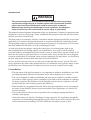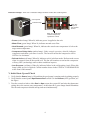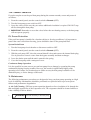
1
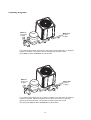
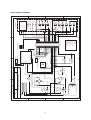
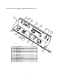
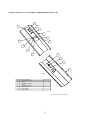
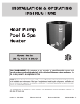
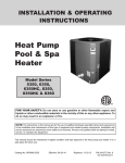
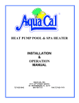
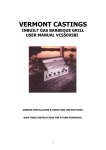
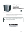
Raypak® RHP Series
Swimming Pool and
Spa Heat Pump
OWNER and
INSTALLATION MANUAL
Model RHP 33
R
C
LI S
TED
US
9900276
This manual should be maintained in legible condition and kept adjacent
to the heat pump or in a safe place for future use.
For additional information call: (03) 9757 3333
The instructions in this manual are for the use of qualified individuals specially
trained and experienced in the installation and maintenance of this type of
equipment and related system components. Installation and service personnel
are required by some states to be licensed.
Persons not qualified must not attempt to install, service, or maintain this
equipment.
The Pool and Spa Heating Experts
Effective Date: Dec 2004
Replaces: All Previous Versions
Part No.
PRODUCT SAFETY SIGNS AND LABELS
Recognize this symbol in the
manual as an indication of
important safety information!
This manual, as well as the pool/spa heat pump itself, contains product safety signs and labels.
Please read these signs and labels, as they convey important safety information about
hazards that may be potentially present in and around the heat pump. They are classified
according to relative seriousness of the hazard potential, from DANGER at the most serious, to
WARNING, or CAUTION at the least serious.
An example of a heat pump safety label follows.
CAUTION
Excessive chemical content in a swimming pool or spa will damage the heat pump.
DO NOT skimmer feed - Avoid adding chemicals in this manner.
AUDIENCE
The audience for this manual is twofold:
1. For the installing contractor, to provide information for the proper installation and
adjustment of the heat pump;
2. For the owner-operator, to explain the features, operation, safety precautions, and service/
maintenance of the heat pump. The manual also includes system drawings and illustrated
replacement parts lists.
WARRANTY CLAIMS (See the enclosed Warranty information)
For the Warranty to apply, proper authorisation MUST be obtained PRIOR to making any repairs.
This Warranty is VOID if the product is repaired or altered in any way by ANY persons or
agencies other than those authorised by Raypak or Rheem Service.
The heat pump Warranty will be VOID if chemical levels are not maintained within the limits
stated in the Warranty Information - Warranty Exclusions section of this manual.
CONTACT INFORMATION
Sales : RAYPAK Australia (a division of Rheem Australia)
39 Koornang Road, Scoresby Victoria 3179
Phone: 1300 725 729
Service: 131 031
www.raypak.com.au
i
RHP Series Swimming Pool and Spa Heat Pump
OWNER and INSTALLATION MANUAL
CONTENTS
Introduction. . . . . . . . . . . . . . . . . . . . . . . . . . . . . . . . . . . . . . . . . . . . . . . . . . . . . . . . . . . . . 1
I. Installation . . . . . . . . . . . . . . . . . . . . . . . . . . . . . . . . . . . . . . . . . . . . . . . . . . . . . . . . . . . . 1
II. Electrical Connections . . . . . . . . . . . . . . . . . . . . . . . . . . . . . . . . . . . . . . . . . . . . . . . . . . 2
III. Water Connections . . . . . . . . . . . . . . . . . . . . . . . . . . . . . . . . . . . . . . . . . . . . . . . . . . . . 3
IV. Controls and Indicator Lamps . . . . . . . . . . . . . . . . . . . . . . . . . . . . . . . . . . . . . . . . . . . 3
V. Initial Start-Up and Check . . . . . . . . . . . . . . . . . . . . . . . . . . . . . . . . . . . . . . . . . . . . . . . 4
VI. Seasonal Start-Up or Annual Check . . . . . . . . . . . . . . . . . . . . . . . . . . . . . . . . . . . . . . . 5
VII. Heat Pump Running Time. . . . . . . . . . . . . . . . . . . . . . . . . . . . . . . . . . . . . . . . . . . . . . 5
VIII. Summer Shutdown. . . . . . . . . . . . . . . . . . . . . . . . . . . . . . . . . . . . . . . . . . . . . . . . . . . 6
IX. Freeze Protection . . . . . . . . . . . . . . . . . . . . . . . . . . . . . . . . . . . . . . . . . . . . . . . . . . . . . 6
X. Maintenance . . . . . . . . . . . . . . . . . . . . . . . . . . . . . . . . . . . . . . . . . . . . . . . . . . . . . . . . . . 6
XI. Troubleshooting . . . . . . . . . . . . . . . . . . . . . . . . . . . . . . . . . . . . . . . . . . . . . . . . . . . . . . 7
Plumbing Diagrams . . . . . . . . . . . . . . . . . . . . . . . . . . . . . . . . . . . . . . . . . . . . . . . . . . . . . 10
Heat Pump Schematic . . . . . . . . . . . . . . . . . . . . . . . . . . . . . . . . . . . . . . . . . . . . . . . . . . . . 11
Control Panel Assembly Replacement Parts List . . . . . . . . . . . . . . . . . . . . . . . . . . . . . . . 12
Control Panel Cover Assembly Replacement Parts List . . . . . . . . . . . . . . . . . . . . . . . . . 13
Heat Pump Assembly Replacement Parts List - RHP 33 . . . . . . . . . . . . . . . . . . . . . . . . . 14
Limited Warranty Information . . . . . . . . . . . . . . . . . . . . . . . . . . . . . . . . . . . . . . . . . . . . . 15
EXCLUSIVE WARRANTY - LIMITATION OF LIABILITY. . . . . . . . . . . . . . . . . . . . 16
ii
Introduction
WARNING
This pool/spa heat pump is an electromechanical machine that incorporates
a pressurised refrigerant gas in a sealed system. ONLY trained and qualified
service personnel should attempt to install or service this equipment.
Without proper training and knowledge of such equipment, any attempt to
install or service the unit could result in serious injury or even death.
This manual contains important information on the use, maintenance, chemistry requirements and
installation of your new heat pump. Proper installation and operation of the unit will increase the
benefits you receive from the unit.
This heat pump is an extremely efficient, economical machine designed specifically for pool and
spa heating. It is similar in design and operation to a typical residential air conditioning system.
The heat pump employs a hermetic motor/compressor operating in a refrigeration cycle to extract
heat from ambient air and deliver it to the circulating pool water.
As with all pool/spa heat pumps, compared to other types of pool heat pumps such as gas,
this heat pump has lower heating capacity on a KW/hr basis. As a result, it will be required
to operate longer to accomplish the desired results. It may, at certain times, operate as much as 24
hours per day. However, this should not be of concern to the owner, because the unit is designed
to operate continuously. Even though it may operate continuously for many hours, it will still heat
the pool with greater economy than other types of fossil fuel heaters.
You are advised to put a pool cover over the pool at night and other non-use periods. This will
keep evaporation, the cause of the greatest heat loss, to a minimum, and so greatly reduce overall
pool heating costs. During warmer weather, the pool cover may be required only at night.
I. Installation
• The placement of the pool heat pump is very important to minimize installation costs while
providing maximum efficiency of operation, and to allow adequate service access.
• The unit is designed for outdoor installation and must not be installed in a totally enclosed
area such as a shed or garage, unless ventilation is provided to ensure adequate air exchange
for proper operation. Recirculation of cold discharge air back into the evaporator coil will
greatly reduce the unit’s heating capacity and efficiency.
• When installed in a geographical location where freezing temperatures can be encountered,
the water circuit should be drained to prevent possible freeze-up damage. See Section IX,
Freeze Protection.
• The unit should be located as close as possible to the existing pool pump and filter to
minimize water piping.
• All models feature an "up-flow" discharge for quiet operation. Air is pulled up through the
evaporator coil and discharged through the top grill. Allow at least 2.5m clearance above the
unit for unrestricted air discharge. Do NOT install the unit under a porch or deck.
1
• Each side of the unit must be located at least 300mm from walls, pipes, or other obstructions
for unrestricted air intake and service access.
WARNING
Do not install the unit within 1m of fossil fuel burning heaters. Air intake
along the sides of this heat pump could disturb the combustion process
of the unit, and could cause damage or personal injury.
• Mount the unit on a level, sturdy base, preferably a concrete slab or blocks. The size of the
base should be not less than 1m by 1m.
• Completely isolate the base from the building foundation or wall to prevent sound or
vibration transmission into the building. For this purpose, 4 black rubber sound isolation
pads are included with the unit. These pads must be installed under the corners of the
unit to reduce vibration and sound transmission to the base.
• If the unit is installed in an area known for water accumulation during periods of heavy
rainfall, its supporting base must be high enough to keep it completely free of standing water
at all times.
II. Electrical Connections
The table below lists the typical electrical power requirements for your heat pump.
Table 1: Typical System Electrical Power Requirements
Model
RHP 33
VIN - Phase - Hz
Min. circuit Ampacity (A)
Max. breaker size (A)
42.2
60
240 - 1 - 50
Refer to the unit rating plate below the control panel for precise power requirement for each unit,
and for ampacity and over-current protection requirements. All wiring must be in accordance with
the AS3000 Wiring Rules Section 7.2 Swimming Pools, latest edition, and all applicable state
and local codes.
The power supply connections to the unit are located behind the control panel. Remove the
control panel to expose the electrical controls. Line voltage connections are made at the line
voltage terminals of the compressor contactor. Refer to the Heat Pump Schematic (page 11) and
the Control Panel Assembly Replacement Parts List (page 12).
Conduit entrance to the unit is through a hole below the control panel.
NOTE: Make certain all electrical connections to unit terminals are secure.
2
III. Water Connections
CAUTION
The heat pump inlet and outlet connections are NOT interchangeable.
They must be connected as instructed below.
1. Connect the heat pump in the return water line between the pool filter and the pool. See
page 10, Plumbing Diagrams.
2. Connect the filter outlet to the fitting marked WATER IN at the bottom front of the unit.
3. Connect the fitting marked WATER OUT to the return piping to the pool. Unit inlet/outlet
connection fittings are 50mm PVC slip couplers.
Water connections from the heat pump to the main return line can be PVC pipe or flexible pipe
approved for the purpose and, in either case, should be at least equal in size to the main pool
circulation piping.
4. In cold weather (freeze zone) areas, shutoff valves (ball or gate type) must be installed at the
heat pump inlet and outlet to facilitate service and cold weather drain-down.
5. When the water connections are complete, operate the pool pump and check the system for
leaks.
Automatic chemical feeders must not be installed upstream of the heat pump. Improper
installation of erosion-type automatic chemical feeders can result in serious damage to, or
premature failure of, the heat pump. A flow check valve will be required.
IV. Controls and Indicator Lamps
Your heat pump incorporates safety controls and indicators to ensure its safe, reliable operation.
Water Pressure Switch: Prevents operation when the pump is OFF. The unit requires 35 Kpa
minimum pressure.
Water Temperature Control: Pool/spa water temperature is controlled by the heat pump
thermostat on the unit control panel, which contains a switch and 2 thermostats, one for setting a
spa temperature and the other for a swimming pool temperature. The switch can operate an
optional external control system, or can switch between thermostats for pool or spa.
NOTE: The heat pump will not run when the Remote position is selected
and there is no remote control system attached.
Defrost Switch: Prevents heat pump operation if ambient air temperature falls below a
predetermined safe minimum (approximately 5.5°C).
Delay Timer: Prevents compressor from short cycling, which could damage or destroy the
hermetic motor/compressor. Upon water temperature control satisfaction, or other control circuit
interruption, this solid state device will prevent compressor restart for approximately 5 minutes.
Upon power failure or interruption, a 6 to 8 minute delay will also be initiated.
Refrigerant Low Pressure Control: Stops the compressor if refrigerant suction (low side)
pressure falls too low as a result of a malfunction or loss of charge.
3
Indicator Lamps: There are 6 indicator lamps located on the unit control panel:
Control panel
Indicator lamps
When this
lamp is lit,
unit requires
service.
When any combination
of these 5 lamps is lit,
operation is normal.
• Power (amber lamp): When lit, indicates power is applied to the unit.
• Water Flow (green lamp): When lit, indicates normal water flow.
• Heat Demand (green lamp): When lit, indicates the actual water temperature is below the
target water temperature.
• Compressor Delay Active (amber lamp): Under normal operation, when lit, indicates
compressor anti-short cycle timer is active. The fan will run but the compressor will be
OFF for 6 to 8 minutes.
• Defrost Active (red lamp): When lit, indicates unit is in defrost mode. Defrost mode occurs
when ice starts to form on the outside coil. The fan will continue to run but the compressor
will stay OFF (not heating) until weather conditions improve.
• Low Pressure (red lamp): When lit, indicates failure in the refrigeration circuit. When this
lamp is ON, service is required. Call the number shown in the CONTACT INFORMATION
at the front of this manual.
V. Initial Start-Up and Check
1. Verify that the Power lamp is ON and that the pool pump is running and circulating properly.
2. Verify that the control panel Spa-Remote-Pool switch is in the Remote (OFF) position; see
the figure.
3. Turn the control switch to either Pool or Spa to turn the system ON and raise the thermostat
setting above the current water temperature. At this time the 2 green lamps should illuminate.
The fan and compressor should start up and run simultaneously.
4
NOTE: The heat pump will be OFF when the Remote
position is selected on the Pool/Spa selector switch.
Spa thermostat
Pool/Spa selector
switch
Pool thermostat
4.Allow the heat pump to operate for a few minutes to
stabilize operating pressures and to allow various
component temperatures to normalize.
5. Verify that the discharge air temperature is
approximately 4°C - 6°C cooler than the air entering the
unit.
VI. Seasonal Start-Up or Annual Check
1. Remove leaves, pine needles, etc. from the evaporator coil. Clean the coil by spraying it with
a mild solution of household liquid soap and water.
2. Flush the coil with a garden hose; DO NOT use a high-pressure sprayer.
3. Backwash or otherwise clean the pool filter. If necessary, clean the skimmer basket and pump
strainer.
4. Set the valves to assure proper water flow through the unit.
5. Set the water temperature control to the desired temperature range for either pool or spa.
6. Turn the control switch to either Pool or Spa. If the pool pump is running and the water is
colder than the setting of the temperature control, the heat pump will start up and run. It will
run until the desired water temperature is reached, or until the pool pump shuts OFF.
NOTE: If the pool pump and heat pump shut OFF before the water temperature is
raised to the desired level, you must lengthen the running time of both. To do this,
reset the time clock dial for the longer running time, or manually operate the pump
with the timer override switch. Since the pool heat pump capacity and efficiency are
both greater at higher ambient air temperatures, run time should be set to take
advantage of all daylight hours, when the air is generally warmer.
VII. Heat Pump Running Time
1. Determine the length of pump and heat pump operating time necessary for your particular
requirements. Minimum run time should be the required hours to attain proper pool water
filtration. Maximum run time obviously is 24 hours per day, or as required to reach desired
pool temperature, and depends on such things as weather, pool size, covering, shading, etc.
2. If cooler or warmer water is desired, simply adjust the water temperature control and/or the
pump and heat pump operating time accordingly, until the desired water temperature is
reached.
NOTE: At the beginning of the heating season, or whenever the pool water
temperature is to be raised several degrees, the pool pump and heat pump may
need to operate continuously for several days. During summer months, only a few
hours per day may be necessary, or none at all.
5
VIII. Summer Shutdown
If you do not plan to use the pool heat pump during the summer months, secure and protect it
as follows:
1. From the control panel, turn the control switch to Remote (OFF).
2. Turn the heat pump power switch to OFF.
3. Leave the valves set the way they are unless additional circulation is required. DO NOT stop
all flow through the heat pump.
4. IMPORTANT: Remember to reset the valves before the next heating season, or the heat pump
will not operate properly.
IX. Freeze Protection
If the pool heat pump is installed in a location subject to freezing conditions, it is important to
protect the water circuit from freezing, just as should be done for the pump and filter.
System Drain-Down
1. Turn the heat pump circuit breaker or disconnect switch to OFF.
2. From the control panel, turn the control switch to Remote (OFF).
3. With the pool pump OFF, close the external shutoff valves and remove the internal drain plug.
Use air pressure to remove water from the bypass assembly and heat exchanger.
4. Leave the drains open until the unit is started in the spring.
5. Cover the heat pump with a waterproof cover.
Continuous Pump Operation
It is also possible in some areas to prevent heat pump freeze damage by operating the pump
continuously during freezing weather. However, this results in significantly higher pump
operating cost. Further, if a sustained power failure occurs, the heat pump would have to be
drained anyway, or freeze damage could result.
X. Maintenance
The following maintenance procedures are designed to keep your heat pump operating at a high
level of reliability. Maintenance should be performed on a periodic basis to prevent system
failures and performance degradation.
A. Air Coil Cleaning - Efficient system operation depends on free circulation of air through the
thin and tightly-spaced fins of the evaporator coils. The evaporator should be cleaned whenever
it has a buildup of dirt or debris.
1.
WARNING
Shut OFF electricity to the heat pump.
6
2.
To clean the fins, spray with a garden hose. But avoid high water
pressure, which will bend and damage the fins.
CAUTION
B. Cabinet Care (optional) - The cabinet is designed for outdoor use and requires little care.
However, you can clean it if you wish.
1.
WARNING
Shut OFF electricity to the heat pump.
2. Wash the cabinet with soap and water.
C. Condensate Drainage - The heat pump extracts humidity from the air as it passes through the
coil, similar to the way a cold drink outside “sweats” on a hot day. This condensate drains from
the bottom of the unit.
1. Routinely check to be sure the condensate drain holes in the base of the unit are not plugged
with dirt or debris.
NOTE: Owners often suspect that the heat pump is leaking when in fact it is
condensate that is draining. To check that the liquid is condensate and not
leakage from the heat pump, either:
a. Use the pool chemistry test kit to confirm there is no chlorine in the condensate. Or,
b. Shut the heat pump OFF and leave the filter pump running to see if the water disappears.
If the water disappears, it would confirm the water to be condensate.
XI. Troubleshooting
If your heat pump does not operate, or simply does not heat your pool water, the indicator lamps
on the front control panel (see page 4) can provide valuable clues as to what is wrong, and may
even indicate precisely what the problem is. Always observe these lamps before calling a service
representative. By reporting on the telephone which lamps are ON and OFF, the service rep may
be able to solve the problem without the expense of a service call.
A. UNIT IS RUNNING, BUT NOT HEATING
• Is the ejected air from the unit 4° to 6° cooler than incoming air? If so, the unit is extracting
heat from the air and transferring it to the pool.
• Are the evaporator and internal copper pipes “sweating”? This is also evidence of heat
removal from the air. When the air is cool with low humidity, “sweating” may not be
evident.
• How long has the heater been operating? During initial pool heating in cold weather, it may
require a week to elevate the pool temperature to a comfortable level. Normally, it takes
about 4 days.
• How many hours per day is the unit operating? Remember that the heat pump only
operates while the pool pump is running. Set the pool system time clock to permit
24 hour per day
7
operation. After the desired temperature is reached, return the system to normal operation.
• Is airflow through the unit being obstructed? Restrictions such as shrubbery, tall grass, dirty
coils, or any other obstruction to airflow will reduce performance.
• Is the pool blanket/cover being used? Unblanketed pools can lose up to 6° per night
compared to 2 degrees or less when a blanket is used. Without a blanket, the total heat
gained during the day can be lost overnight.
• Are rapid heat losses occurring in some other way, such as high wind, waterfalls, spa
spillage, bubblers, rainfall, flow through solar panels at nights, or a high water table?
• Is water flow through the unit adequate? Check the system for obstructions, such as a
clogged filter pump strainer or a dirty filter.
B. UNIT IS NOT RUNNING
• Is the control panel Power lamp ON? If not, the power switch may be shut OFF or circuit
breaker tripped. Reset the power by switching it OFF, then back ON.
Verify that the circuit breaker is set and operating properly before calling for service.
• Is the thermostat setting correct? Verify that the temperature has been properly set on the
thermostat, and that it is higher than the current water temperature.
• Have you waited 6 minutes for the time delay? After the unit has been running and then shut
OFF for any reason, there is a 6-minutes timed cycle before operation can begin again.
• Is the Water Flow lamp OFF? This lamp will turn OFF if not enough water is flowing
through the heater. Improperly positioned valves or a dirty filter could decrease the flow of
water required for efficient operation. When the Water Flow lamp is ON, proper flow is
present. If this lamp is OFF, but you can feel normal flow at the pool returns, check the water
valves or settings.
• Is the Defrost Active lamp OFF? If this lamp is ON, the fan will be running but not the
compressor. The unit is waiting for the frost to melt or the air temperature to rise before
heating is resumed.
• Is the Heat Demand lamp ON? If not, then the thermostat setting is not higher than the
temperature of the pool water. Raise the thermostat setting.
• Is the Low Pressure lamp ON? If this lamp is ON, there is a problem with the unit that will
require service. Turn the unit OFF and call the number shown in the CONTACT
INFORMATION at the beginning of this manual.
SERVICE CALL REQUESTS
Determine if the problem is:
• Warranty Service (within 5 years of installation)
• Non Warranty Service (beyond 5 years of installation)
• Maintenance-related (power supply, water flow, or pool system time clock adjustment)
NOTE: The MANUFACTURER IS NOT RESPONSIBLE for maintenance adjustments.
8
POWER SUPPLY
• Verify that all circuit breakers are reset and working properly.
• If the Power lamp on the control panel still does not light, contact the installing dealer,
since it may be a power problem requiring an electrician.
WATER FLOW
• Verify that the filter is clean to provide good flow.
• Verify that the valves are properly positioned.
• If the Water Flow lamp on the control panel still does not light, and water is circulating
in the pool or spa, contact the installing dealer to adjust the valves.
TIME CLOCK ADJUSTMENT
Verify that the time clock is set to permit the heater to run long enough to heat properly.
9
Plumbing Diagrams
Water In
(from pool
or Spa)
Water Out
(to pool
or Spa)
Filter
For systems with pumps of less than 2 HP(1.5Kw) (under 300 l/min), no external
bypass is required. Connections are 50 mm pipe slip. Plumb the heat
pump after the filter and before any chlorinators.
Water In
(from pool
or Spa)
Water Out
(to pool
or Spa)
Filter
For systems with pumps of 2 HP (1.5Kw) or greater (over 300 l/min), an external
bypass is required. Adjust the bypass valve to divert a minimum of 150 l/min
gpm through the heat pump. Connections are 50mm pipe slip. Plumb
the heat pump after the filter and before any chlorinators.
10
Heat Pump Schematic
A
B
C
D
Legend
2
C = Capacitor
D = Diode, LED
F = Fuse
K = Relay, Contactor
M = Motor
R= Resistor, Pot
RT = Thermistor
S = Switch
T = Transformer
TB = Terminal Block
U = Un-repairable Assembly
Black
+24 V/Power Lamp
Defrost Lamp
Compressor Lamp
Water Flow Lamp
GND
Defrost Compressor
Heat Demand Lamp
+ Low Pressure Lamp
- Low Pressure Lamp
Spa Temp
Pool Temp
Pool/Spa SW
Common E2
Temp Sensor +
Temp Sensor E1 [C-ECS] Red
N.C.
TCO Common
TCO Pool
TCO Spa
Remote Total Black
Remote Common
Remote Spa Black
Remote Pool Black
Control Panel Interface
TB1
1
2
3
4
5
6
7
8
9
10
11
12
13
14
15
16
17
18
19
20
21
22
23
24
U1
Pot
Black
High Pressure Switch
S1
Blue
Low Pressure Switch
Blue
S2
Black
Pink
Orange
W hite
Tan
Black
Black
Blue/Black
Black
1
K3
Delay Timer
3
3
W hite
F2
1 Amp
Yellow
C1
Black
T1
Blue
Red
Purple
C2
240VAC
208VAC
4
Blue
Red
K1
K2
W hite
Compressor
Contactor
Blue
White
Fan Relay
208/230 V 1-Phase 60 Hz
Black
Brown
M2
S
Compressor Motor
C
M1
R
Pink
Green
Fan Motor
Water Flow
S4
GND
208/230 V 1-Phase 60 Hz
Sheet1 of1
Drawn By:
4
Lisa
Revision
Schematic, Heat Pump
27-Jan-2003
C:\Pool Fact\Poofact\Poofact.ddb
Number
Tan
Defrost Switch
S3
Black
Tan
Size
Title
Orange
Optional Water Temp Sensor
RT1
E7
E11
E10
E13
E12
Water Temp Sensor
Water Temp Thermostat
Pot
Pink
1
Power
Water Flow
D1
D2
Heat Demand
Defrost
Active
Compressor
Delay Active
D3
D4
D5
Low
Pressure
1
2
3
4
5
6
7
8
9
10
11
12
Spa
Pool
Temp Sensor +
T C S P
Remote Interface
E5
RT2
A
3
Date:
File:
B
D
C
B
A
11
Coil
Coil
D6
S5
R2
R1
Pool/Spa Switch
U2
+V
Temp Sensor -
GND
LCD Temp Display
2
E6
D
C
B
A
Control Panel
1
E4
Control Panel Assembly Replacement Parts List
1
12
4
7
13
11
11
9
6
15
3
16
10
14
5
8
ITEM
1
2
3
4
5
6
7
8
9
10
11
12
13
14
15
16
QTY
1
1
1
1
1
1
1
1
1
1
2
4
2
1
1
1
DESCRIPTION
Control Panel
Contactor Compressor
Fan Relay
Control Board 24Volt
Thermostat
Transformer
Timer IMC 203
Capacitor
Pressure Switch Water
Fuse Block
Bushing Heyco 2184
Stand-off RLCBSR1
Terminal Strip
Clamp Capacitor 04
Ground Lug
Fuse 2A Type 3AG
PART No.
2
12
Control Panel Cover Assembly Replacement Parts List
4
5
4
4
Front
1
6
6
7
8
8
7
2
3
2
1
Back
ITEM
1
2
3
4
5
6
7
8
QTY
1
2
1
3
1
2
2
2
DESCRIPTION
Control Panel Cover
POT
Switch Type A403
Knob
Label Control Panel
Lamp Green
Lamp Red
Lamp Amber
PART No.
RHP Control Panel Cover
13
Heat Pump Assembly Replacement Parts List - RHP 33
11
ITEM
1
2
3
4
5
6
7
8
9
10
11
12
13
14
15
16
17
18
19
13
15
12
5
9
QTY
1
1
1
1
1
1
3
1
2
1
1
1
1
1
1
1
1
1
1
DESCRIPTION
Assembly Base
Evaporator Coil
Access Panel
Power Input Panel
Cover, Top
Compressor, Scroll
Corner Support
Heat Exchanger
Retainer, Screen
Control Panel Cover
Fan Guard
Fan Blade
Fan Motor
Water Manifold Assembly
Conduit, Fan
Coil Guard
Control Panel Assembly
Expansion Valve
Filter Dryer BFK-165 S
PART No.
*
*
*See assembly drawing in this manual
18
7
2
16
3
14
7
9
7
17
19
6
10
8
Model RHP 33
4
1
14
15
16