1
OB381A--1.qxp
10.5.25 9:28 AM
Page 1
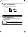
Revision B:
• The fan guard for MUCFH-GA 60VB- E1
has been changed.
Please void OB381 REVSED EDITION-A.
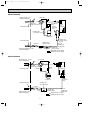
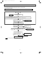
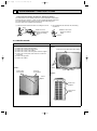
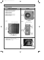
FLOOR AND CEILING TYPE AIR CONDITIONERS
OUTDOOR UNIT
SERVICE MANUAL
HFC
utilized
No. OB381
REVISED EDITION-B
R410A
Models
MUCFH-GA35VB MUCFH-GA50VB MUCFH-GA60VB -
E1
E1
E1
Indoor unit service manual
MCFH-GA•VB Series (OB380)
CONTENTS
MUCFH-GA50VB
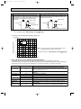
1. TECHNICAL CHANGES ····································2
2. PART NAMES AND FUNCTIONS······················5
3. SPECIFICATION·················································6
4. NOISE CRITERIA CURVES ·······························7
5. OUTLINES AND DIMENSIONS ·························8
6. WIRING DIAGRAM ··········································10
7. REFRIGERANT SYSTEM DIAGRAM ··············11
8. PERFORMANCE CURVES ······························13
9. ACTUATOR CONTROL····································24
10. SERVICE FUNCTIONS·····································24
11. TROUBLESHOOTING ······································25
12. DISASSEMBLY INSTRUCTIONS·····················35
13. PARTS LIST······················································42
14. RoHS PARTS LIST···········································48
NOTE:
This service manual describes technical data of the outdoor units.
RoHS compliant products have <G> mark on the spec name plate.
For servicing of RoHS compliant products, refer to the RoHS PARTS LIST (RoHS compliant).
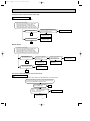
OB381A--1.qxp
10.5.25 9:28 AM
Page 2
Revision A :
• RoHS PARTS LIST has been added.
Revision B :
• The fan guard for MUCFH-GA 60VB-
1
E1
has been changed.
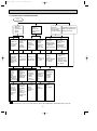
TECHNICAL CHANGES
MUH-A12YV - E1
➔ MUCFH-GA35VB - E1
1. Indication of capacity has been changed. (BTU base ➔ kW)
MUCFH-A18WV - E1 ➔ MUCFH-GA50VB - E1
1. Indication of capacity has been changed. (BTU base ➔ kW)
MUCFH-A24WV - E1 ➔ MUCFH-GA60VB - E1
1. Indication of capacity has been changed. (BTU base ➔ kW)
INFORMATION FOR THE AIR CONDITIONER WITH R410A REFRIGERANT
• This room air conditioner adopts HFC refrigerant (R410A) which never destroys the ozone layer.
• Pay particular attention to the following points, though the basic installation procedure is same as that for R22 conditioners.
1 As R410A has working pressure approximate 1.6 times as high as that of R22, some special tools and piping parts/
materials are required. Refer to the table below.
2 Take sufficient care not to allow water and other contaminations to enter the R410A refrigerant during storage and
installation, since it is more susceptible to contaminations than R22.
3 For refrigerant piping, use clean, pressure-proof parts/materials specifically designed for R410A. (Refer to 2. Refrigerant
piping.)
4 Composition change may occur in R410A since it is a mixed refrigerant. When charging, charge liquid refrigerant to prevent
composition change.
New refrigerant
R410A
R22
Composition (Ratio)
HFC-32: HFC-125 (50%:50%)
R22 (100%)
Refrigerant handling
Pseudo-azeotropic refrigerant
Single refrigerant
Not included
Included
Refrigerant
Chlorine
A1/A1
A1
72.6
86.5
Boiling point (:)
-51.4
-40.8
Steam pressure [25:](Mpa)
1.557
0.94
64
44.4
Non combustible
Non combustible
0
0.055
Refrigerant
Safety group (ASHRAE)
Molecular weight
Saturated steam density [25:](Kg/K)
Combustibility
ODP w1
GWP w2
Refrigerant charge method
1730
1700
From liquid phase in cylinder
Gas phase
Possible
Possible
Kind
Incompatible oil
Compatible oil
Color
Non
Light yellow
Smell
Non
Non
oil
Additional charge on leakage
Refrigeration
Previous refrigerant
w1 :Ozone Destruction Parameter : based on CFC-11
w2 :Global Warmth Parameter
: based on CO2
2
OB381A--1.qxp
10.5.25 9:28 AM
Page 3
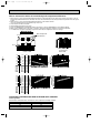
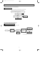
Compressor
New Specification
Current Specification
The incompatible refrigeration oil easily separates from
Since refrigerant and refrigerating oil are compatible each,
refrigerant and is in the upper layer inside the suction muffler. refrigeration oil goes back to the compressor through the
Raising position of the oil back hole enables to back the
lower position oil back hole.
refrigeration oil of the upper layer to flow back to the
compressor.
Suction muffler
Suction muffler
Oil back hole
Compressor
Compressor
Refrigeration oil
Oil back hole
Refrigeration oil /Refrigerant
Refrigerant
NOTE : The unit of pressure has been changed to MPa on the international system of units(SI unit system).
f [Gauge])
The conversion factor is: 1(MPa [Gauge]) =10.2(kgf/f
Conversion chart of refrigerant temperature and pressure
(MPa [Gauge])
4.0
Saturated liquid pressure
3.5
R410A
3.0
R22
2.5
2.0
NOTE : The unit of pressure has been changed to MPa on the
international system of units(SI unit system).
1.5
1.0
f [Gauge])
The conversion factor is: 1(MPa [Gauge]) =10.2(kgf/f
0.5
0.0
-0.5
-30 -20 -10
0
10
20
30
40
50
60
(:)
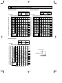
1.Tools dedicated for the air conditioner with R410A refrigerant
The following tools are required for R410A refrigerant. Some R22 tools can be substituted for R410A tools.
The diameter of the service port on the stop valve in outdoor unit has been changed to prevent any other refrigerant being
charged into the unit. Cap size has been changed from 7/16 UNF with 20 threads to 1/2 UNF with 20 threads.
R410A tools
Gauge manifold
No
Charge hose
No
Gas leak detector
Torque wrench
Description
Can R22 tools be used?
R410A has high pressures beyond the measurement range of existing
gauges. Port diameters have been changed to prevent any other refrigerant
from being charged into the unit.
No
Hose material and cap size have been changed to improve the pressure
resistance.
Dedicated for HFC refrigerant.
Yes
6.35 mm and 9.52 mm
No
12.7 mm and 15.88 mm
Flare tool
Yes
Clamp bar hole has been enlarged to reinforce the spring strength in the tool.
Flare gauge
Vacuum pump
adapter
Electronic scale for
refrigerant charging
New
Provided for flaring work (to be used with R22 flare tool).
Provided to prevent the back flow of oil. This adapter enables you to use
vacuum pumps.
It is difficult to measure R410A with a charging cylinder because the
refrigerant bubbles due to high pressure and high-speed vaporization
New
New
No : Not Substitutable for R410A
Yes : Substitutable for R410A
3
OB381A--1.qxp
10.5.25 9:28 AM
Page 4
2.Refrigerant piping
1 Specifications
Use the refrigerant pipes that meet the following specifications.
Outside diameter
Pipe
mm
Wall
thickness
6.35
0.8 mm
9.52
0.8 mm
Heat resisting foam plastic
12.7
0.8 mm
Specific gravity 0.045 Thickness 8 mm
15.88
1.0 mm
For liquid
For gas
Insulation material
• Use a copper pipe or a copper-alloy seamless pipe with a thickness of 0.8 mm (6.35, 9.52, 12.7), 1.0 mm (15.88).
Never use any pipe with a thickness less than 0.8 mm (6.35, 9.52, 12.7), 1.0 mm (15.88), as the pressure resistance is
insufficient.
2 Flaring work and flare nut
Flaring work for R410A pipe differs from that for R22 pipe.
For details of flaring work, refer to Installation manual “FLARING WORK”.
Dimension of flare nut
Pipe diameter
mm
R410A
R22
6.35
17
17
9.52
22
22
12.7
26
24
15.88
29
27
3.Refrigerant oil
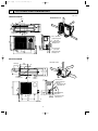
Apply the special refrigeration oil (accessories: packed with indoor unit) to the flare and the union seat surfaces.
4.Air purge
• Do not discharge the refrigerant into the atmosphere.
Take care not to discharge refrigerant into the atmosphere during installation, reinstallation, or repairs to the refrigerant
circuit.
• Use the vacuum pump for air purging for the purpose of environmental protection.
5.Additional charge
For additional charging, charge the refrigerant from liquid phase of the gas cylinder.
If the refrigerant is charged from the gas phase, composition change may occur in the refrigerant inside the cylinder and the
outdoor unit. In this case, ability of the refrigeration cycle decreases or normal operation can be impossible. However,
charging the liquid refrigerant all at once may cause the compressor to be locked. Thus, charge the refrigerant slowly.
Union
Stop valve
Indoor unit
Liquid pipe
Outdoor unit
Gas pipe
Refrigerant gas
cylinder
operating valve
Service port
Gauge manifold
valve (for R410A)
Charge hose (for R410A)
Refrigerant gas cylinder
for R410A with siphon
Refrigerant (liquid)
Electronic scale for refrigerant charging
4
OB381A--1.qxp
2
10.5.25 9:28 AM
Page 5
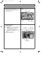
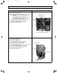
PART NAMES AND FUNCTIONS
MUCFH-GA50VB
MUCFH-GA35VB
Air inlet
(back and side)
Air inlet
(back and side)
Piping
Piping
Drain hose
Drain hose
Air outlet
Air outlet
Drain outlet
Drain outlet
MUCFH-GA60VB
Air inlet
(back and side)
Piping
Drain hose
Air outlet
Drain outlet
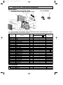
ACCESSORIES
Item
Drain socket
Drain cap [33
Drain cap [16
Q'ty
MUCFH-GA50VB
1
2
1
MUCFH-GA35VB
1
2
–
5
MUCFH-GA60VB
1
2
–
OB381A--1.qxp
3
10.5.25 9:28 AM
Page 6
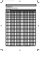
SPECIFICATION
Outdoor model
MUCFH-GA35VB
MUCFH-GA50VB
MUCFH-GA60VB
Function
Heating
Cooling
Single phase
230V, 50Hz
3.7
3.5
—
1.5
1,710
10
4.23
4.85
954
1,094
98
29
3.92
4.54
0.31
3.63
3.02
RN135VHSHT
900
C-R 2.79
C-S 3.36
RA6V33-JB
WHT-BLK 215.1
BLK-RED 306.9
780o540o255
40
49
825
1
Heating
Cooling
Single phase
230V, 50Hz
5.0
4.8
—
2.4
2,196
15
8.38
8.01
1,810
1,730
94
37
7.99
7.62
0.39
2.65
2.65
RN196VHSHT
1,300
C-R 1.80
C-S 3.00
RA6V50-PA
WHT-BLK 79.5
BLK-RED 83.0
850o605o290
47
52
828
1
Cooling
Heating
Single phase
230V, 50Hz
6.0
6.8
3.1
—
2,760
25
10.51
11.71
2,370
2,640
98
74
9.93
11.13
0.58
2.45
2.50
NN29VBAHT
1,900
C-R 0.80
C-S 1.64
RA6V85-DA
WHT-BLK 68.8
BLK-RED 93.1
840o850o330
74
53
730
1
1.00
1.85
2.20
620 (NEO22)
33.18
520 (NEO22)
33.18
1,200 (NEO22)
33.18
Capacity
Power supply
Special
remarks
Fan
Compressor
motor
Electrical
data
Capacity
kW
Dehumidification
r/h
Air flow(High)
K /h
Power outlet
A
Running current
A
Power input
W
Power factor
%
Starting current
A
Compressor motor current
A
Fan motor current
A
Coefficient of performance(C.O.P)
Model
Output
W
Winding
"
resistance(at 20:)
Model
Winding
"
resistance(at 20:)
Dimensions WOHOD
mm
Weight
kg
Sound level(High)
dB
Fan speed(High)
rpm
Fan speed regulator
Refrigerant filling
kg
capacity(R410A)
Refrigeration oil (Model)
cc
Thermistor RT61(at 0:)
k"
NOTE: Test conditions are based on ISO 5151.
Cooling : Indoor DB27°C WB19°C
Heating : Indoor DB20°C WB 15.5°C
Outdoor DB35°C WB(24°C)
Outdoor DB 7°C WB 6°C
Indoor-Outdoor piping length : 5m
6
OB381A--1.qxp
10.5.25 9:28 AM
4
Page 7
NOISE CRITERIA CURVES
MUCFH-GA50VB
MUCFH-GA35VB
SPL(dB(A))
FUNCTION
FUNCTION
LINE
COOLING
COOLING
49
Test conditions,
Cooling : Dry-bulb temperature 35: Wet-bulb temperature (24:)
Heating : Dry-bulb temperature 7: Wet-bulb temperature 6:
OCTAVE BAND SOUND PRESSURE LEVEL, dB re 0.0002 MICRO BAR
OCTAVE BAND SOUND PRESSURE LEVEL, dB re 0.0002 MICRO BAR
80
70
NC-70
60
NC-60
50
NC-50
40
NC-40
30
NC-30
APPROXIMATE
TERESHOLD OF
HEARING FOR
CONTINUOUS
NOISE
NC-20
10
125
250
500
1000
2000
4000
8000
80
70
NC-70
60
NC-60
50
NC-50
40
NC-40
30
NC-30
20
10
APPROXIMATE
THRESHOLD OF
HEARING FOR
CONTINUOUS
NOISE
63
125
NC-20
250
500
1000
MUCFH-GA60VB
SPL(dB(A))
COOLING
LINE
53
HEATING
OCTAVE BAND SOUND PRESSURE LEVEL, dB re 0.0002 MICRO BAR
Test conditions,
Cooling : Dry-bulb temperature 35: Wet-bulb temperature (24:)
Heating : Dry-bulb temperature 7: Wet-bulb temperature 6:
90
80
OUTDOORUNIT
70
NC-70
1m
60
MICROPHONE
NC-60
50
NC-50
40
NC-40
30
NC-30
20
10
APPROXIMATE
THRESHOLD OF
HEARING FOR
CONTINUOUS
NOISE
63
125
NC-20
250
500
1000
2000
4000
2000
4000
BAND CENTER FREQUENCIES, Hz
BAND CENTER FREQUENCIES, Hz
FUNCTION
52
Test conditions,
Cooling : Dry-bulb temperature 35: Wet-bulb temperature (24:)
Heating : Dry-bulb temperature 7: Wet-bulb temperature 6:
90
90
63
LINE
HEATING
HEATING
20
SPL(dB(A))
8000
BAND CENTER FREQUENCIES, Hz
7
8000
OB381A--1.qxp
5
10.5.25 9:28 AM
Page 8
OUTLINES AND DIMENSIONS
Unit: mm
100mm or more
MUCFH-GA35VB
REQUIRED SPACE
Air in
32
320
100
or m
ore
255
285
320
109
mm
ore
rm
mo
m
100
Air in
Drainage
3 holes [33
147
110
Air out
ore
25
m
00m
or m
4
35
0m
Service panel
m
43- 35-
540
155
90
260
10
122
500
780
mo
re
Liquid refrigerant
pipe joint
Refrigerant pipe
(flared) [6.35
40
or
104
74
Gas refrigerant
pipe joint
Refrigerant pipe
(flared) [12.7
MUCFH-GA50VB
REQUIRED SPACE
355
350
Air in
20
Air out
50
30
e
mor
Service panel
20
100
157
35-
292
30-
605
Liquid refrigerant
pipe joint
Refregerant pipe
(flared) [6.35
500
850
161
74
8
e
mor
mor
e
m or
500m
183
m or
100m
345
Air in
310
290
248
90
100m
m or
Drainage
3 holes [33
100mm or more
35
Drainage
hole [16.2
Gas refregerant
pipe joint
Refregerant pipe
(flared) [12.7
350
mm
or m
ore
OB381A--1.qxp
10.5.25 9:28 AM
Page 9
Unit: mm
MUCFH-GA60VB
Open as a rule
500mm or more if
the front and both
sides are open
REQUIRED SPACE
515
299
100mm or more
200mm or more if
there are obstacles
to both sides
40
66
360
330
51
34
100mm or more
500
840
121
Open as a rule
500mm or more if the back,
80 both sides and top are open
350mm or more
Service panel
155
90
35-
30-
430
850
Liquid refrigerant
pipe joint
Refrigerant pipe
(flared) [6.35
198
9
Gas refrigerant
pipe joint
Refrigerant pipe
(flared) [15.88
OB381A--1.qxp
6
10.5.25 9:28 AM
Page 10
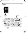
WIRING DIAGRAM
MUCFH-GA35VB
21S4
RT61
N
CN661
BRN
CN711
1 WHT
2 BLK
3 RED
SR61
F61
BRN
T61
BLU
TAB20
230V 50Hz
CN721
NR61
POWER SUPPLY
~/N
BLK
DSAR
TB1
L
1
2
3
SR62
N
CIRCUIT BREAKER
MF
RED
CN730
TB2
3
TO
INDOOR UNIT
CONNECTING
12V
C65
52C
PE
GRN/YLW
4
3
DEICER P.C.BOARD
C
WHT
C1
BLU
RED
S
BLK
NAME
SYMBOL
SYMBOL
C1
COMPRESSOR CAPACITOR
C65
OUTDOOR FAN CAPACITOR
MF
MC
R
SYMBOL
NAME
NAME
TRANSFORMER
T61
OUTDOOR FAN MOTOR
(INNER FUSE)
TB1,TB2
TERMINAL BLOCK
SURGE ABSORBER
NR61
VARISTOR
21S4
R.V. COIL
F61
FUSE(2A)
RT61
DEFROST THERMISTOR
52C
COMPRESSOR CONTACTOR
MC
COMPRESSOR(INNER PROTECTOR) SR61,SR62 SOLID STATE RELAY
DSAR
NOTE:1. About the indoor side electric wiring refer to the indoor unit electric wiring diagram for servicing.
2. Use copper conductors only. (For field wiring)
3. Symbols below indicate.
/: Terminal block,
: Connector
MUCFH-GA50VB
RED
ORN
WHT
BLK
CN721
SR62
CN661
F61
NR61
N
T61
BLU
1 2 3 4
CN711
WHT
1
BLK
SR61
2
RED
3
C65
52C
TAB20
PE
GRN/YLW
POWER SUPPLY
~ /N
230V 50Hz
1
2
3
DSAR
RED
TO
INDOOR UNIT
N BLK
CONNECTING
12V
TB1 BRN
CIRCUIT BREAKER
L
BRN
CN730
TB2
3
MF
21S4
RT61
4
3
C1
BLU
DEICER P.C.BOARD
RED
WHT
S
BLK
C
MC
R
SYMBOL
NAME
SYMBOL
C1
COMPRESSOR CAPACITOR
MF
C65
OUTDOOR FAN CAPACITOR
NR61
VARISTOR
21S4
R.V. COIL
RT61
DEFROST THERMISTOR
52C
COMPRESSOR CONTACTOR
DSAR
SURGE ABSORBER
F61
FUSE (2A)
MC
COMPRESOR (INNER PROTECTOR)
NAME
SR61,SR62 SOLID STATE RELAY
T61
NAME
SYMBOL
OUTDOOR FAN MOTOR (INNER PROTECTOR) TB1,TB2 TERMINAL BLOCK
TRANSFORMER
NOTES: 1.About the indoor side electric wiring refer to the indoor unit electric wiring diagram for servicing.
2.Use copper conductors only. (For field wiring)
3.Symbols below indicate.
: Connector
: Terminal block
10
OB381A--1.qxp
10.5.25 9:28 AM
Page 11
MUCFH-GA60VB
MF
BLK
WHT
ORN
RED
DSAR
4 3 2 1
BLK
WHT
BRN
RT61
TO INDOOR UNIT CONNECTING
12V
L
TB1
X62
N
X52
RED
ORN
X52
PE
COM
DEICER
P.C.BOARD
COMPRESSOR CAPACITOR
C2
OUTDOOR FAN CAPACITOR
C2
DSAR
CN721
1
2
X62
3
COM
NO
SR61
T61
NAME
C1
CN711
1 2 3
CN661
GRN/YLW
POWER SUPPLY
~/N 230V 50Hz
CIRCUIT BREAKER
SYMBOL
21S4
TAB52
4
WHT
52C
N
BLU
DEFROST THERMISTOR
SOLID STATE RELAY
TB1
TERMINAL BLOCK
TB2
TERMINAL BLOCK
T61
TRANSFORMER
RED
X52
CONTACTOR
X62
R. V. COIL RELAY
21S4
R. V. COIL
52C
COMPRESSOR CONTACTOR
S MC R
BLK
BLU
A1
52C
A2
OUTDOOR FAN MOTOR (INNER PROTECTOR)
RT61
C
C1
MF
SR61
TB2
3
COMPRESSOR (INNER PROTECTOR)
VARISTOR
BLU
BRN
FUSE (3.15A)
MC
NR61
BRN
3
F61
NO
CN730 7
5
3
F61
1
NR61
SURGE ABSORBER
BLU
RED
BLU
NOTES: 1.Use copper conductors only (For field wiring).
2.Since the indoor and outdoor unit connecting wires have polarity, connect them according to the numbers (3,N).
3.Symbols below indicate.
: Terminal block,
: Connector
7
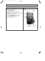
REFRIGERANT SYSTEM DIAGRAM
MUCFH-GA35VB
Unit:mm
Refrigerant pipe [12.7
(with heat insulator)
4-way valve
Stop valve
(with service port)
Flared connection
Muffler
Defrost
thermistor
RT61
Outdoor
heat
exchanger
Capillary tube
[3.0x[1.4x500(2pcs)
Compressor
Capillary tube
[3.0x[1.6x600
Flared connection
Strainer
#100
Capillary tube
[3.0x[1.6x1050
R.V. coil
heating ON
cooling OFF
Stop valve
Refrigerant flow in cooling
Refrigerant pipe [6.35
(with heat insulator)
Check
valve
11
Refrigerant flow in heating
OB381A--1.qxp
10.5.25 9:28 AM
Page 12
MUCFH-GA50VB
4- way valve
Refrigerant pipe [12.7
(with heat insulator)
Oil separator
#100
Stop valve
(with service port)
Outdoor
heat
exchanger
Defrost
thermistor
RT61
Flared connection
Capillary tube
[2.5o[0.6o1,000
Compressor
Capillary tube
[3.0o[1.6o750
(2 pcs)
Flared connection
Capillary tube
[3.0o[1.6o650
Receiver
Stop
Refrigerant pipe[6.35 valve
(with heat insulator)
Strainer
#100
Check valve
R.V. coil
Heating ON
Cooling OFF
Capillary tube
[3.0o[1.6o500
Refrigerant flow in cooling
Refrigerant flow in heating
MUCFH-GA60VB
Refrigerant pipe [15.88
(with heat insulator)
4- way valve
Stop valve
(with service port)
Flared connection
Muffler
#100
Muffler
Compressor
Flared connection
Outdoor
heat
exchanger
Defrost
thermistor
RT61
Capillary tube
[3.0X[2.0X400
Receiver
Stop valve
Refrigerant pipe [6.35
(with heat insulator)
R.V. coil
Capillary tube
Strainer
Heating ON
[3.0X[2.0X800
#100
Cooling OFF
Check valve
Refrigerant flow in cooling
Refrigerant flow in heating
12
OB381A--1.qxp
10.5.25 9:28 AM
Page 13
MAX. REFRIGERANT PIPING LENGTH & MAX. HEIGHT DIFFERENCE
Refrigerant piping
MAX. length : m
A
Model
Piping size O.D. : mm
Gas
MUCFH-GA35VB
Liquid
{12.7
25
MUCFH-GA50VB
{6.35
{15.88
MUCFH-GA60VB
W Max. Height
difference
10m
wIt does not matter which unit is higher.
A: Refrigerant piping Max.length 25m
ADDITIONAL REFRIGERANT CHARGE (R410A : g)
If pipe length exceeds 7m, additional refrigerant (R410A) charge is required.
Models
Outdoor unit:
precharged
MUCFH-GA35VB
1,000
MUCFH-GA50VB
1,850
MUCFH-GA60VB
2,200
Refrigerant piping length (one way)
7m
10m
15m
20m
25m
0
60
160
260
360
Calculation : ✕g = 20g/m ✕ (Refrigerant piping length (m)-7)
8
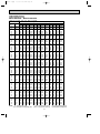
PERFORMANCE CURVES
MUCFH-GA35VB
MUCFH-GA50VB
MUCFH-GA60VB
The standard data contained in these specifications apply only to the operation of the air conditioner under normal condition.
Operating conditions vary according to the areas where these units are installed. The following information has been provided
to clarify the operating characteristics of the air conditioner under the conditions indicated by the performance curve.
(1) GUARANTEED VOLTAGE
198~264V, 50Hz
(2) AIR FLOW
Air flow should be set at MAX.
(3) MAIN READINGS
HEATING
(1) Indoor intake air dry-bulb temperature : ˚CDB
(2) Indoor outlet air dry-bulb temperature : ˚CDB
(3) Outdoor intake air wet-bulb temperature : ˚CWB
(4) Total input : W
COOLING
(1) Indoor intake air wet-bulb temperature : ˚CWB
(2) Indoor outlet air wet-bulb temperature : ˚CWB
(3) Outdoor intake air dry-bulb temperature : ˚CDB
(4) Total input : W
Indoor air wet/dry-bulb temperature difference on the left side of the chart on next page shows the difference between
the indoor intake air wet/dry-bulb temperature and the indoor outlet air wet/dry-bulb temperature for your reference at
service.
13
OB381A--1.qxp
10.5.25 9:28 AM
Page 14
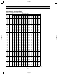
How to measure the indoor air wet-bulb/dry-bulb temperature difference
1. Attach at least 2 sets of wet and dry-bulb thermometers to the indoor air inlet as shown in the figure, and at least 2 sets of
wet and dry bulb thermometers to the indoor air outlet. The thermometers must be attached to the position where air speed
is high.
2. Attach at least 2 sets of wet and dry-bulb thermometers to the outdoor air inlet.
Cover the thermometers to prevent direct rays of the sun.
3. Check that the air filter is cleaned.
4. Open windows and doors of the room.
5. Press the EMERGENCY OPERATION switch once(twice) to start the EMERGENCY COOL(HEAT) MODE.
6. When system stabilizes after more than 15 minutes, measure temperature and take an average temperature.
7. 10 minutes later, measure temperature again and check that the temperature does not change.
INDOOR UNIT
OUTDOOR UNIT
Wet and dry-bulb
thermometers
Air out
Air in
Wet and dry-bulb
thermometers
BACK VIEW
14.7
8.0
10.2
13.4
7.3
9.2
12.1
6.6
8.3
10.9
5.9
7.5
9.7
5.3
6.6
8.5
MUCFH-GA50VB
MCFH-GA60VB
MUCFH-GA60VB
23.4
21.6
19.8
18.0
16.2
14.4
12.6
10.8
31.8
29.3
26.9
24.4
22.0
19.5
17.1
14.7
MCFH-GA60VB
MUCFH-GA60VB
18.6
17.2
15.7
14.3
12.9
11.5
10.0
8.6
MCFH-GA50VB
MUCFH-GA50VB
MCFH-GA50VB
11.1
MUCFH-GA35VB
8.7
MCFH-GA35VB
MUCFH-GA35VB
MCFH-GA35VB
FRONT VIEW
OUTDOOR LOW PRESSURE AND OUTDOOR UNIT CURRENT
COOL operation
1 Both indoor and outdoor units are under the same temperature/humidity condition.
Dry Bulb temperature (˚C)
20
25
30
Relative humidity (%)
50
60
70
14
OB381A--1.qxp
10.5.25 9:28 AM
Page 15
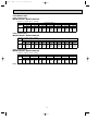
2 Air flow should be set at MAX.
3 The unit of pressure has been changed to MPa on the international system of units(SI unit system).
f [Gauge])
The conversion factor is : 1(MPa [Gauge]) =10.2(kgf/f
MUCFH-GA35VB
13
1.3
12
1.2
11
1.1
10
1.0
9
0.9
8
0.8
7
0.7
15
6
230V
18 20
50
25
60
Outdoor unit current (A)
Outdoor low pressure
(kgf/F[Gauge])(MPa[Gauge])
230V
5
4
3
15
30 32 35(:)
(%)
70
18 20
50
25
60
30 32
70
35(:)
(%)
Ambient temperature(˚C)
Ambient humidity(%)
Ambient temperature(˚C)
Ambient humidity(%)
MUCFH-GA50VB
12
1.2
11
11
1.1
10
10
1.0
9
0.9
Outdoor unit current (A)
Outdoor low pressure
(kgf/F [Gauge]) (MPa [Gauge])
230V
8
0.8
7
0.7
6
0.6
15
9
230V
8
7
6
5
15 18 20
25
30 32 35(:)
50
60
70
(%)
Ambient temperature (:)
Ambient humidity (%)
18 20
25
30 32 35(:)
50
60
70
(%)
Ambient temperature (:)
Ambient humidity (%)
MUCFH-GA60VB
11
1.1
12
10
1.0
11
9
0.9
8
0.8
7
0.7
6
0.6
5
0.5
15
Outdoor unit current (A)
Outdoor low pressure
(kgf/F [Gauge]) (MPa [Gauge])
230V
230V
10
9
8
7
6
15 18 20
25
30 32 35(:)
50
60
70
(%)
Ambient temperature (:)
Ambient humidity (%)
18 20
25
30 32 35(:)
50
60
70
(%)
Ambient temperature (:)
Ambient humidity (%)
15
OB381A--1.qxp
10.5.25 9:29 AM
Page 16
HEAT operation
Condition Indoor : Dry bulb temerature 20.0:
Wet bulb temerature 14.5:
MUCFH-GA35VB
Outdoor : Dry bulb temerature 7,15,20:
Wet bulb temerature 6,12,14.5:
MUCFH-GA50VB
6
Outdoor unit current (A)
Outdoor unit current (A)
11
230V
5
4
3
5
7
10
50
15
60
20 21
70
MUCFH-GA60VB
Outdoor unit current (A)
16
230V
14
13
12
11
5 7
10
15
20
50
60
70
Ambient temperature (:)
Ambient humidity (%)
10
9
8
5 7
25 (:)
(%)
Ambient temperature(˚C)
Ambient humidity(%)
15
230V
25(:)
(%)
16
10
15
20
50
60
70
Ambient temperature (:)
Ambient humidity (%)
25(:)
(%)
OB381A--1.qxp
10.5.25 9:29 AM
Page 17
PERFORMANCE DATA
COOL operation (230V)
MCFH-GA35VB : MUCFH-GA35VB
CAPACITY :3.5(kW) SHF :0.70 INPUT :1160(W)
21
Q SHC SHF
18
4.11 2.14 0.52
20
4.29 1.72 0.40
18
4.11 2.30 0.56
20
4.29 1.89 0.44
22
4.46 1.43 0.32
18
4.11 2.47 0.60
20
4.29 2.06 0.48
22
4.46 1.61 0.36
18
4.11 2.63 0.64
20
4.29 2.23 0.52
22
4.46 1.79 0.40
24
4.69 1.31 0.28
18
4.11 2.80 0.68
20
4.29 2.40 0.56
22
4.46 1.96 0.44
24
4.69 1.50 0.32
18
4.11 2.96 0.72
20
4.29 2.57 0.60
22
4.46 2.14 0.48
24
4.69 1.69 0.36
26
4.83 1.16 0.24
18
4.11 3.13 0.76
20
4.29 2.74 0.64
22
4.46 2.32 0.52
24
4.69 1.88 0.40
26
4.83 1.35 0.28
18
4.11 3.29 0.80
20
4.29 2.92 0.68
22
4.46 2.50 0.56
24
4.69 2.06 0.44
26
4.83 1.55 0.32
18
4.11 3.45 0.84
20
4.29 3.09 0.72
22
4.46 2.68 0.60
24
4.69 2.25 0.48
26
4.83 1.74 0.36
18
4.11 3.62 0.88
20
4.29 3.26 0.76
22
4.46 2.86 0.64
24
4.69 2.44 0.52
26
4.83 1.93 0.40
18
4.11 3.78 0.92
20
4.29 3.43 0.80
22
4.46 3.03 0.68
24
4.69 2.63 0.56
26
4.83 2.13 0.44
18
4.11 3.95 0.96
20
4.29 3.60 0.84
22
4.46 3.21 0.72
24
4.69 2.81 0.60
26
4.83 2.32 0.48
Q :Total capacity (kW)
SHC :Sensible heat capacity
INDOOR INDOOR
DB(:) WB(:)
21
21
22
22
22
23
23
23
24
24
24
24
25
25
25
25
26
26
26
26
26
27
27
27
27
27
28
28
28
28
28
29
29
29
29
29
30
30
30
30
30
31
31
31
31
31
32
32
32
32
32
NOTE
INPUT
928
974
928
974
1009
928
974
1009
928
974
1009
1056
928
974
1009
1056
928
974
1009
1056
1114
928
974
1009
1056
1114
928
974
1009
1056
1114
928
974
1009
1056
1114
928
974
1009
1056
1114
928
974
1009
1056
1114
928
974
1009
1056
1114
(kW)
OUTDOOR DB(:)
25
27
30
Q SHC SHF INPUT Q SHC SHF INPUT Q SHC SHF INPUT
3.94 2.05 0.52 974 3.78 1.97 0.52 1021 3.64 1.89 0.52 1067
4.11 1.65 0.40 1032 3.99 1.60 0.40 1056 3.85 1.54 0.40 1102
3.94 2.21 0.56 974 3.78 2.12 0.56 1021 3.64 2.04 0.56 1067
4.11 1.81 0.44 1032 3.99 1.76 0.44 1056 3.85 1.69 0.44 1102
4.31 1.38 0.32 1073 4.20 1.34 0.32 1102 4.03 1.29 0.32 1148
3.94 2.36 0.60 974 3.78 2.27 0.60 1021 3.64 2.18 0.60 1067
4.11 1.97 0.48 1032 3.99 1.92 0.48 1056 3.85 1.85 0.48 1102
4.31 1.55 0.36 1073 4.20 1.51 0.36 1102 4.03 1.45 0.36 1148
3.94 2.52 0.64 974 3.78 2.42 0.64 1021 3.64 2.33 0.64 1067
4.11 2.14 0.52 1032 3.99 2.07 0.52 1056 3.85 2.00 0.52 1102
4.31 1.72 0.40 1073 4.20 1.68 0.40 1102 4.03 1.61 0.40 1148
4.52 1.26 0.28 1114 4.41 1.23 0.28 1148 4.27 1.20 0.28 1206
3.94 2.68 0.68 974 3.78 2.57 0.68 1021 3.64 2.48 0.68 1067
4.11 2.30 0.56 1032 3.99 2.23 0.56 1056 3.85 2.16 0.56 1102
4.31 1.89 0.44 1073 4.20 1.85 0.44 1102 4.03 1.77 0.44 1148
4.52 1.44 0.32 1114 4.41 1.41 0.32 1148 4.27 1.37 0.32 1206
3.94 2.84 0.72 974 3.78 2.72 0.72 1021 3.64 2.62 0.72 1067
4.11 2.47 0.60 1032 3.99 2.39 0.60 1056 3.85 2.31 0.60 1102
4.31 2.07 0.48 1073 4.20 2.02 0.48 1102 4.03 1.93 0.48 1148
4.52 1.63 0.36 1114 4.41 1.59 0.36 1148 4.27 1.54 0.36 1206
4.69 1.13 0.24 1172 4.62 1.11 0.24 1206 4.48 1.08 0.24 1241
3.94 2.99 0.76 974 3.78 2.87 0.76 1021 3.64 2.77 0.76 1067
4.11 2.63 0.64 1032 3.99 2.55 0.64 1056 3.85 2.46 0.64 1102
4.31 2.24 0.52 1073 4.20 2.18 0.52 1102 4.03 2.09 0.52 1148
4.52 1.81 0.40 1114 4.41 1.76 0.40 1148 4.27 1.71 0.40 1206
4.69 1.31 0.28 1172 4.62 1.29 0.28 1206 4.48 1.25 0.28 1241
3.94 3.15 0.80 974 3.78 3.02 0.80 1021 3.64 2.91 0.80 1067
4.11 2.80 0.68 1032 3.99 2.71 0.68 1056 3.85 2.62 0.68 1102
4.31 2.41 0.56 1073 4.20 2.35 0.56 1102 4.03 2.25 0.56 1148
4.52 1.99 0.44 1114 4.41 1.94 0.44 1148 4.27 1.88 0.44 1206
4.69 1.50 0.32 1172 4.62 1.48 0.32 1206 4.48 1.43 0.32 1241
3.94 3.31 0.84 974 3.78 3.18 0.84 1021 3.64 3.06 0.84 1067
4.11 2.96 0.72 1032 3.99 2.87 0.72 1056 3.85 2.77 0.72 1102
4.31 2.58 0.60 1073 4.20 2.52 0.60 1102 4.03 2.42 0.60 1148
4.52 2.17 0.48 1114 4.41 2.12 0.48 1148 4.27 2.05 0.48 1206
4.69 1.69 0.36 1172 4.62 1.66 0.36 1206 4.48 1.61 0.36 1241
3.94 3.47 0.88 974 3.78 3.33 0.88 1021 3.64 3.20 0.88 1067
4.11 3.13 0.76 1032 3.99 3.03 0.76 1056 3.85 2.93 0.76 1102
4.31 2.76 0.64 1073 4.20 2.69 0.64 1102 4.03 2.58 0.64 1148
4.52 2.35 0.52 1114 4.41 2.29 0.52 1148 4.27 2.22 0.52 1206
4.69 1.88 0.40 1172 4.62 1.85 0.40 1206 4.48 1.79 0.40 1241
3.94 3.62 0.92 974 3.78 3.48 0.92 1021 3.64 3.35 0.92 1067
4.11 3.29 0.80 1032 3.99 3.19 0.80 1056 3.85 3.08 0.80 1102
4.31 2.93 0.68 1073 4.20 2.86 0.68 1102 4.03 2.74 0.68 1148
4.52 2.53 0.56 1114 4.41 2.47 0.56 1148 4.27 2.39 0.56 1206
4.69 2.06 0.44 1172 4.62 2.03 0.44 1206 4.48 1.97 0.44 1241
3.94 3.78 0.96 974 3.78 3.63 0.96 1021 3.64 3.49 0.96 1067
4.11 3.45 0.84 1032 3.99 3.35 0.84 1056 3.85 3.23 0.84 1102
4.31 3.10 0.72 1073 4.20 3.02 0.72 1102 4.03 2.90 0.72 1148
4.52 2.71 0.60 1114 4.41 2.65 0.60 1148 4.27 2.56 0.60 1206
4.69 2.25 0.48 1172 4.62 2.22 0.48 1206 4.48 2.15 0.48 1241
SHF :Sensible heat factor
DB :Dry-bulb temperature
INPUT :Total power input (W)
WB :Wet-bulb temperature
17
OB381A--1.qxp
10.5.25 9:29 AM
Page 18
PERFORMANCE DATA
COOL operation (230V)
MCFH-GA35VB : MUCFH-GA35VB
CAPACITY :3.5(kW) SHF :0.70 INPUT :1160(W)
OUTDOOR DB(:)
35
40
INDOOR INDOOR
DB(:) WB(:) Q SHC SHF INPUT Q SHC SHF INPUT Q
21
18
3.43 1.78 0.52 1137 3.15 1.64 0.52 1206 3.03
21
20
3.61 1.44 0.40 1183 3.36 1.34 0.40 1241 3.24
22
18
3.43 1.92 0.56 1137 3.15 1.76 0.56 1206 3.03
22
20
3.61 1.59 0.44 1183 3.36 1.48 0.44 1241 3.24
22
22
3.82 1.22 0.32 1230 3.57 1.14 0.32 1299 3.45
23
18
3.43 2.06 0.60 1137 3.15 1.89 0.60 1206 3.03
23
20
3.61 1.73 0.48 1183 3.36 1.61 0.48 1241 3.24
23
22
3.82 1.37 0.36 1230 3.57 1.29 0.36 1299 3.45
24
18
3.43 2.20 0.64 1137 3.15 2.02 0.64 1206 3.03
24
20
3.61 1.87 0.52 1183 3.36 1.75 0.52 1241 3.24
24
22
3.82 1.53 0.40 1230 3.57 1.43 0.40 1299 3.45
24
24
4.03 1.13 0.28 1276 3.78 1.06 0.28 1334 3.68
25
18
3.43 2.33 0.68 1137 3.15 2.14 0.68 1206 3.03
25
20
3.61 2.02 0.56 1183 3.36 1.88 0.56 1241 3.24
25
22
3.82 1.68 0.44 1230 3.57 1.57 0.44 1299 3.45
25
24
4.03 1.29 0.32 1276 3.78 1.21 0.32 1334 3.68
26
18
3.43 2.47 0.72 1137 3.15 2.27 0.72 1206 3.03
26
20
3.61 2.16 0.60 1183 3.36 2.02 0.60 1241 3.24
26
22
3.82 1.83 0.48 1230 3.57 1.71 0.48 1299 3.45
26
24
4.03 1.45 0.36 1276 3.78 1.36 0.36 1334 3.68
26
26
4.24 1.02 0.24 1322 3.99 0.96 0.24 1380 3.87
27
18
3.43 2.61 0.76 1137 3.15 2.39 0.76 1206 3.03
27
20
3.61 2.31 0.64 1183 3.36 2.15 0.64 1241 3.24
27
22
3.82 1.98 0.52 1230 3.57 1.86 0.52 1299 3.45
27
24
4.03 1.61 0.40 1276 3.78 1.51 0.40 1334 3.68
27
26
4.24 1.19 0.28 1322 3.99 1.12 0.28 1380 3.87
28
18
3.43 2.74 0.80 1137 3.15 2.52 0.80 1206 3.03
28
20
3.61 2.45 0.68 1183 3.36 2.28 0.68 1241 3.24
28
22
3.82 2.14 0.56 1230 3.57 2.00 0.56 1299 3.45
28
24
4.03 1.77 0.44 1276 3.78 1.66 0.44 1334 3.68
28
26
4.24 1.36 0.32 1322 3.99 1.28 0.32 1380 3.87
29
18
3.43 2.88 0.84 1137 3.15 2.65 0.84 1206 3.03
29
20
3.61 2.60 0.72 1183 3.36 2.42 0.72 1241 3.24
29
22
3.82 2.29 0.60 1230 3.57 2.14 0.60 1299 3.45
29
24
4.03 1.93 0.48 1276 3.78 1.81 0.48 1334 3.68
29
26
4.24 1.52 0.36 1322 3.99 1.44 0.36 1380 3.87
30
18
3.43 3.02 0.88 1137 3.15 2.77 0.88 1206 3.03
30
20
3.61 2.74 0.76 1183 3.36 2.55 0.76 1241 3.24
30
22
3.82 2.44 0.64 1230 3.57 2.28 0.64 1299 3.45
30
24
4.03 2.09 0.52 1276 3.78 1.97 0.52 1334 3.68
30
26
4.24 1.69 0.40 1322 3.99 1.60 0.40 1380 3.87
31
18
3.43 3.16 0.92 1137 3.15 2.90 0.92 1206 3.03
31
20
3.61 2.88 0.80 1183 3.36 2.69 0.80 1241 3.24
31
22
3.82 2.59 0.68 1230 3.57 2.43 0.68 1299 3.45
31
24
4.03 2.25 0.56 1276 3.78 2.12 0.56 1334 3.68
31
26
4.24 1.86 0.44 1322 3.99 1.76 0.44 1380 3.87
32
18
3.43 3.29 0.96 1137 3.15 3.02 0.96 1206 3.03
32
20
3.61 3.03 0.84 1183 3.36 2.82 0.84 1241 3.24
32
22
3.82 2.75 0.72 1230 3.57 2.57 0.72 1299 3.45
32
24
4.03 2.42 0.60 1276 3.78 2.27 0.60 1334 3.68
32
26
4.24 2.03 0.48 1322 3.99 1.92 0.48 1380 3.87
NOTE
Q :Total capacity (kW)
SHF :Sensible heat factor
SHC :Sensible heat capacity (kW)
INPUT :Total power input (W)
18
43
SHC SHF INPUT
1.57 0.52 1230
1.30 0.40 1276
1.70 0.56 1230
1.42 0.44 1276
1.10 0.32 1322
1.82 0.60 1230
1.55 0.48 1276
1.24 0.36 1322
1.94 0.64 1230
1.68 0.52 1276
1.38 0.40 1322
1.03 0.28 1363
2.06 0.68 1230
1.81 0.56 1276
1.52 0.44 1322
1.18 0.32 1363
2.18 0.72 1230
1.94 0.60 1276
1.65 0.48 1322
1.32 0.36 1363
0.93 0.24 1409
2.30 0.76 1230
2.07 0.64 1276
1.79 0.52 1322
1.47 0.40 1363
1.08 0.28 1409
2.42 0.80 1230
2.20 0.68 1276
1.93 0.56 1322
1.62 0.44 1363
1.24 0.32 1409
2.54 0.84 1230
2.33 0.72 1276
2.07 0.60 1322
1.76 0.48 1363
1.39 0.36 1409
2.66 0.88 1230
2.46 0.76 1276
2.21 0.64 1322
1.91 0.52 1363
1.55 0.40 1409
2.79 0.92 1230
2.59 0.80 1276
2.34 0.68 1322
2.06 0.56 1363
1.70 0.44 1409
2.91 0.96 1230
2.72 0.84 1276
2.48 0.72 1322
2.21 0.60 1363
1.86 0.48 1409
DB :Dry-bulb temperature
WB :Wet-bulb temperature
OB381A--1.qxp
10.5.25 9:29 AM
Page 19
PERFORMANCE DATA COOL operation(230V)
MCFH-GA50VB : MUCFH-GA50VB
CAPACITY :4.8(kW) SHF :0.65 INPUT :1810(W)
OUTDOOR DB(:)
21
Q SHC SHF INPUT
18
5.64 2.65 0.47 1448
20
5.88 2.06 0.35 1520
18
5.64 2.88 0.51 1448
20
5.88 2.29 0.39 1520
22
6.12 1.65 0.27 1575
18
5.64 3.10 0.55 1448
20
5.88 2.53 0.43 1520
22
6.12 1.90 0.31 1575
18
5.64 3.33 0.59 1448
20
5.88 2.76 0.47 1520
22
6.12 2.14 0.35 1575
24
6.43 1.48 0.23 1647
18
5.64 3.55 0.63 1448
20
5.88 3.00 0.51 1520
22
6.12 2.39 0.39 1575
24
6.43 1.74 0.27 1647
18
5.64 3.78 0.67 1448
20
5.88 3.23 0.55 1520
22
6.12 2.63 0.43 1575
24
6.43 1.99 0.31 1647
26
6.62 1.26 0.19 1738
18
5.64 4.00 0.71 1448
20
5.88 3.47 0.59 1520
22
6.12 2.88 0.47 1575
24
6.43 2.25 0.35 1647
26
6.62 1.52 0.23 1738
18
5.64 4.23 0.75 1448
20
5.88 3.70 0.63 1520
22
6.12 3.12 0.51 1575
24
6.43 2.51 0.39 1647
26
6.62 1.79 0.27 1738
18
5.64 4.46 0.79 1448
20
5.88 3.94 0.67 1520
22
6.12 3.37 0.55 1575
24
6.43 2.77 0.43 1647
26
6.62 2.05 0.31 1738
18
5.64 4.68 0.83 1448
20
5.88 4.17 0.71 1520
22
6.12 3.61 0.59 1575
24
6.43 3.02 0.47 1647
26
6.62 2.32 0.35 1738
18
5.64 4.91 0.87 1448
20
5.88 4.41 0.75 1520
22
6.12 3.86 0.63 1575
24
6.43 3.28 0.51 1647
26
6.62 2.58 0.39 1738
18
5.64 5.13 0.91 1448
20
5.88 4.65 0.79 1520
22
6.12 4.10 0.67 1575
24
6.43 3.54 0.55 1647
26
6.62 2.85 0.43 1738
Q : Total capacity (kW)
SHC : Sensible heat capacity (kW)
INDOOR INDOOR
DB(:) WB(:)
21
21
22
22
22
23
23
23
24
24
24
24
25
25
25
25
26
26
26
26
26
27
27
27
27
27
28
28
28
28
28
29
29
29
29
29
30
30
30
30
30
31
31
31
31
31
32
32
32
32
32
NOTE
25
Q SHC SHF INPUT Q
5.40 2.54 0.47 1520 5.18
5.64 1.97 0.35 1611 5.47
5.40 2.75 0.51 1520 5.18
5.64 2.20 0.39 1611 5.47
5.90 1.59 0.27 1674 5.76
5.40 2.97 0.55 1520 5.18
5.64 2.43 0.43 1611 5.47
5.90 1.83 0.31 1674 5.76
5.40 3.19 0.59 1520 5.18
5.64 2.65 0.47 1611 5.47
5.90 2.07 0.35 1674 5.76
6.19 1.42 0.23 1738 6.05
5.40 3.40 0.63 1520 5.18
5.64 2.88 0.51 1611 5.47
5.90 2.30 0.39 1674 5.76
6.19 1.67 0.27 1738 6.05
5.40 3.62 0.67 1520 5.18
5.64 3.10 0.55 1611 5.47
5.90 2.54 0.43 1674 5.76
6.19 1.92 0.31 1738 6.05
6.43 1.22 0.19 1828 6.34
5.40 3.83 0.71 1520 5.18
5.64 3.33 0.59 1611 5.47
5.90 2.77 0.47 1674 5.76
6.19 2.17 0.35 1738 6.05
6.43 1.48 0.23 1828 6.34
5.40 4.05 0.75 1520 5.18
5.64 3.55 0.63 1611 5.47
5.90 3.01 0.51 1674 5.76
6.19 2.41 0.39 1738 6.05
6.43 1.74 0.27 1828 6.34
5.40 4.27 0.79 1520 5.18
5.64 3.78 0.67 1611 5.47
5.90 3.25 0.55 1674 5.76
6.19 2.66 0.43 1738 6.05
6.43 1.99 0.31 1828 6.34
5.40 4.48 0.83 1520 5.18
5.64 4.00 0.71 1611 5.47
5.90 3.48 0.59 1674 5.76
6.19 2.91 0.47 1738 6.05
6.43 2.25 0.35 1828 6.34
5.40 4.70 0.87 1520 5.18
5.64 4.23 0.75 1611 5.47
5.90 3.72 0.63 1674 5.76
6.19 3.16 0.51 1738 6.05
6.43 2.51 0.39 1828 6.34
5.40 4.91 0.91 1520 5.18
5.64 4.46 0.79 1611 5.47
5.90 3.96 0.67 1674 5.76
6.19 3.41 0.55 1738 6.05
6.43 2.77 0.43 1828 6.34
SHF : Sensible heat factor
INPUT : Total power input (W)
19
27
30
SHC SHF INPUT Q SHC SHF INPUT
2.44 0.47 1593 4.99 2.35 0.47 1665
1.92 0.35 1647 5.28 1.85 0.35 1720
2.64 0.51 1593 4.99 2.55 0.51 1665
2.13 0.39 1647 5.28 2.06 0.39 1720
1.56 0.27 1720 5.52 1.49 0.27 1792
2.85 0.55 1593 4.99 2.75 0.55 1665
2.35 0.43 1647 5.28 2.27 0.43 1720
1.79 0.31 1720 5.52 1.71 0.31 1792
3.06 0.59 1593 4.99 2.95 0.59 1665
2.57 0.47 1647 5.28 2.48 0.47 1720
2.02 0.35 1720 5.52 1.93 0.35 1792
1.39 0.23 1792 5.86 1.35 0.23 1882
3.27 0.63 1593 4.99 3.14 0.63 1665
2.79 0.51 1647 5.28 2.69 0.51 1720
2.25 0.39 1720 5.52 2.15 0.39 1792
1.63 0.27 1792 5.86 1.58 0.27 1882
3.47 0.67 1593 4.99 3.34 0.67 1665
3.01 0.55 1647 5.28 2.90 0.55 1720
2.48 0.43 1720 5.52 2.37 0.43 1792
1.87 0.31 1792 5.86 1.82 0.31 1882
1.20 0.19 1882 6.14 1.17 0.19 1937
3.68 0.71 1593 4.99 3.54 0.71 1665
3.23 0.59 1647 5.28 3.12 0.59 1720
2.71 0.47 1720 5.52 2.59 0.47 1792
2.12 0.35 1792 5.86 2.05 0.35 1882
1.46 0.23 1882 6.14 1.41 0.23 1937
3.89 0.75 1593 4.99 3.74 0.75 1665
3.45 0.63 1647 5.28 3.33 0.63 1720
2.94 0.51 1720 5.52 2.82 0.51 1792
2.36 0.39 1792 5.86 2.28 0.39 1882
1.71 0.27 1882 6.14 1.66 0.27 1937
4.10 0.79 1593 4.99 3.94 0.79 1665
3.67 0.67 1647 5.28 3.54 0.67 1720
3.17 0.55 1720 5.52 3.04 0.55 1792
2.60 0.43 1792 5.86 2.52 0.43 1882
1.96 0.31 1882 6.14 1.90 0.31 1937
4.30 0.83 1593 4.99 4.14 0.83 1665
3.89 0.71 1647 5.28 3.75 0.71 1720
3.40 0.59 1720 5.52 3.26 0.59 1792
2.84 0.47 1792 5.86 2.75 0.47 1882
2.22 0.35 1882 6.14 2.15 0.35 1937
4.51 0.87 1593 4.99 4.34 0.87 1665
4.10 0.75 1647 5.28 3.96 0.75 1720
3.63 0.63 1720 5.52 3.48 0.63 1792
3.08 0.51 1792 5.86 2.99 0.51 1882
2.47 0.39 1882 6.14 2.40 0.39 1937
4.72 0.91 1593 4.99 4.54 0.91 1665
4.32 0.79 1647 5.28 4.17 0.79 1720
3.86 0.67 1720 5.52 3.70 0.67 1792
3.33 0.55 1792 5.86 3.22 0.55 1882
2.72 0.43 1882 6.14 2.64 0.43 1937
DB : Dry-bulb temperature
WB : Wet-bulb temperature
OB381A--1.qxp
10.5.25 9:29 AM
Page 20
PERFORMANCE DATA COOL operation(230V)
MCFH-GA50VB : MUCFH-GA50VB
CAPACITY :4.8(kW) SHF :0.65 INPUT :1810(W)
OUTDOOR DB(:)
35
40
INDOOR INDOOR
DB(:) WB(:) Q SHC SHF INPUT Q SHC SHF INPUT Q
21
18
4.70 2.21 0.47 1774 4.32 2.03 0.47 1882 4.15
21
20
4.94 1.73 0.35 1846 4.61 1.61 0.35 1937 4.44
22
18
4.70 2.40 0.51 1774 4.32 2.20 0.51 1882 4.15
22
20
4.94 1.93 0.39 1846 4.61 1.80 0.39 1937 4.44
22
22
5.23 1.41 0.27 1919 4.90 1.32 0.27 2027 4.73
23
18
4.70 2.59 0.55 1774 4.32 2.38 0.55 1882 4.15
23
20
4.94 2.13 0.43 1846 4.61 1.98 0.43 1937 4.44
23
22
5.23 1.62 0.31 1919 4.90 1.52 0.31 2027 4.73
24
18
4.70 2.78 0.59 1774 4.32 2.55 0.59 1882 4.15
24
20
4.94 2.32 0.47 1846 4.61 2.17 0.47 1937 4.44
24
22
5.23 1.83 0.35 1919 4.90 1.71 0.35 2027 4.73
24
24
5.52 1.27 0.23 1991 5.18 1.19 0.23 2082 5.04
25
18
4.70 2.96 0.63 1774 4.32 2.72 0.63 1882 4.15
25
20
4.94 2.52 0.51 1846 4.61 2.35 0.51 1937 4.44
25
22
5.23 2.04 0.39 1919 4.90 1.91 0.39 2027 4.73
25
24
5.52 1.49 0.27 1991 5.18 1.40 0.27 2082 5.04
26
18
4.70 3.15 0.67 1774 4.32 2.89 0.67 1882 4.15
26
20
4.94 2.72 0.55 1846 4.61 2.53 0.55 1937 4.44
26
22
5.23 2.25 0.43 1919 4.90 2.11 0.43 2027 4.73
26
24
5.52 1.71 0.31 1991 5.18 1.61 0.31 2082 5.04
26
26
5.81 1.10 0.19 2063 5.47 1.04 0.19 2154 5.30
27
18
4.70 3.34 0.71 1774 4.32 3.07 0.71 1882 4.15
27
20
4.94 2.92 0.59 1846 4.61 2.72 0.59 1937 4.44
27
22
5.23 2.46 0.47 1919 4.90 2.30 0.47 2027 4.73
27
24
5.52 1.93 0.35 1991 5.18 1.81 0.35 2082 5.04
27
26
5.81 1.34 0.23 2063 5.47 1.26 0.23 2154 5.30
28
18
4.70 3.53 0.75 1774 4.32 3.24 0.75 1882 4.15
28
20
4.94 3.11 0.63 1846 4.61 2.90 0.63 1937 4.44
28
22
5.23 2.67 0.51 1919 4.90 2.50 0.51 2027 4.73
28
24
5.52 2.15 0.39 1991 5.18 2.02 0.39 2082 5.04
28
26
5.81 1.57 0.27 2063 5.47 1.48 0.27 2154 5.30
29
18
4.70 3.72 0.79 1774 4.32 3.41 0.79 1882 4.15
29
20
4.94 3.31 0.67 1846 4.61 3.09 0.67 1937 4.44
29
22
5.23 2.88 0.55 1919 4.90 2.69 0.55 2027 4.73
29
24
5.52 2.37 0.43 1991 5.18 2.23 0.43 2082 5.04
29
26
5.81 1.80 0.31 2063 5.47 1.70 0.31 2154 5.30
30
18
4.70 3.90 0.83 1774 4.32 3.59 0.83 1882 4.15
30
20
4.94 3.51 0.71 1846 4.61 3.27 0.71 1937 4.44
30
22
5.23 3.09 0.59 1919 4.90 2.89 0.59 2027 4.73
30
24
5.52 2.59 0.47 1991 5.18 2.44 0.47 2082 5.04
30
26
5.81 2.03 0.35 2063 5.47 1.92 0.35 2154 5.30
31
18
4.70 4.09 0.87 1774 4.32 3.76 0.87 1882 4.15
31
20
4.94 3.71 0.75 1846 4.61 3.46 0.75 1937 4.44
31
22
5.23 3.30 0.63 1919 4.90 3.08 0.63 2027 4.73
31
24
5.52 2.82 0.51 1991 5.18 2.64 0.51 2082 5.04
31
26
5.81 2.27 0.39 2063 5.47 2.13 0.39 2154 5.30
32
18
4.70 4.28 0.91 1774 4.32 3.93 0.91 1882 4.15
32
20
4.94 3.91 0.79 1846 4.61 3.64 0.79 1937 4.44
32
22
5.23 3.51 0.67 1919 4.90 3.28 0.67 2027 4.73
32
24
5.52 3.04 0.55 1991 5.18 2.85 0.55 2082 5.04
32
26
5.81 2.50 0.43 2063 5.47 2.35 0.43 2154 5.30
NOTE
Q : Total capacity (kW)
SHF : Sensible heat factor
SHC : Sensible heat capacity (kW) INPUT : Total power input (W)
20
43
SHC SHF INPUT
1.95 0.47 1919
1.55 0.35 1991
2.12 0.51 1919
1.73 0.39 1991
1.28 0.27 2063
2.28 0.55 1919
1.91 0.43 1991
1.47 0.31 2063
2.45 0.59 1919
2.09 0.47 1991
1.65 0.35 2063
1.16 0.23 2127
2.62 0.63 1919
2.26 0.51 1991
1.84 0.39 2063
1.36 0.27 2127
2.78 0.67 1919
2.44 0.55 1991
2.03 0.43 2063
1.56 0.31 2127
1.01 0.19 2199
2.95 0.71 1919
2.62 0.59 1991
2.22 0.47 2063
1.76 0.35 2127
1.22 0.23 2199
3.11 0.75 1919
2.80 0.63 1991
2.41 0.51 2063
1.97 0.39 2127
1.43 0.27 2199
3.28 0.79 1919
2.97 0.67 1991
2.60 0.55 2063
2.17 0.43 2127
1.64 0.31 2199
3.45 0.83 1919
3.15 0.71 1991
2.79 0.59 2063
2.37 0.47 2127
1.86 0.35 2199
3.61 0.87 1919
3.33 0.75 1991
2.98 0.63 2063
2.57 0.51 2127
2.07 0.39 2199
3.78 0.91 1919
3.51 0.79 1991
3.17 0.67 2063
2.77 0.55 2127
2.28 0.43 2199
DB : Dry-bulb temperature
WB : Wet-bulb temperature
OB381A--1.qxp
10.5.25 9:29 AM
Page 21
PERFORMANCE DATA COOL operation(230V)
MCFH-GA60VB : MUCFH-GA60VB
CAPACITY :6.0(kW) SHF :0.64 INPUT :2450(W)
INDOOR INDOOR
DB(:) WB(:)
21
21
22
22
22
23
23
23
24
24
24
24
25
25
25
25
26
26
26
26
26
27
27
27
27
27
28
28
28
28
28
29
29
29
29
29
30
30
30
30
30
31
31
31
31
31
32
32
32
32
32
NOTE
Q
21
SHC SHF INPUT
18
7.05 3.24 0.46
20
7.35 2.50 0.34
18
7.05 3.53 0.50
20
7.35 2.79 0.38
22
7.65 1.99 0.26
18
7.05 3.81 0.54
20
7.35 3.09 0.42
22
7.65 2.30 0.30
18
7.05 4.09 0.58
20
7.35 3.38 0.46
22
7.65 2.60 0.34
24
8.04 1.77 0.22
18
7.05 4.37 0.62
20
7.35 3.68 0.50
22
7.65 2.91 0.38
24
8.04 2.09 0.26
18
7.05 4.65 0.66
20
7.35 3.97 0.54
22
7.65 3.21 0.42
24
8.04 2.41 0.30
26
8.28 1.49 0.18
18
7.05 4.94 0.70
20
7.35 4.26 0.58
22
7.65 3.52 0.46
24
8.04 2.73 0.34
26
8.28 1.82 0.22
18
7.05 5.22 0.74
20
7.35 4.56 0.62
22
7.65 3.83 0.50
24
8.04 3.06 0.38
26
8.28 2.15 0.26
18
7.05 5.50 0.78
20
7.35 4.85 0.66
22
7.65 4.13 0.54
24
8.04 3.38 0.42
26
8.28 2.48 0.30
18
7.05 5.78 0.82
20
7.35 5.15 0.70
22
7.65 4.44 0.58
24
8.04 3.70 0.46
26
8.28 2.82 0.34
18
7.05 6.06 0.86
20
7.35 5.44 0.74
22
7.65 4.74 0.62
24
8.04 4.02 0.50
26
8.28 3.15 0.38
18
7.05 6.35 0.90
20
7.35 5.73 0.78
22
7.65 5.05 0.66
24
8.04 4.34 0.54
26
8.28 3.48 0.42
Q : Total capacity (kW)
SHC : Sensible heat capacity
1960
2058
1960
2058
2132
1960
2058
2132
1960
2058
2132
2230
1960
2058
2132
2230
1960
2058
2132
2230
2352
1960
2058
2132
2230
2352
1960
2058
2132
2230
2352
1960
2058
2132
2230
2352
1960
2058
2132
2230
2352
1960
2058
2132
2230
2352
1960
2058
2132
2230
2352
(kW)
Q
OUTDOOR DB(:)
25
27
SHC SHF INPUT Q SHC SHF INPUT
6.75 3.11 0.46 2058 6.48
7.05 2.40 0.34 2181 6.84
6.75 3.38 0.50 2058 6.48
7.05 2.68 0.38 2181 6.84
7.38 1.92 0.26 2266 7.20
6.75 3.65 0.54 2058 6.48
7.05 2.96 0.42 2181 6.84
7.38 2.21 0.30 2266 7.20
6.75 3.92 0.58 2058 6.48
7.05 3.24 0.46 2181 6.84
7.38 2.51 0.34 2266 7.20
7.74 1.70 0.22 2352 7.56
6.75 4.19 0.62 2058 6.48
7.05 3.53 0.50 2181 6.84
7.38 2.80 0.38 2266 7.20
7.74 2.01 0.26 2352 7.56
6.75 4.46 0.66 2058 6.48
7.05 3.81 0.54 2181 6.84
7.38 3.10 0.42 2266 7.20
7.74 2.32 0.30 2352 7.56
8.04 1.45 0.18 2475 7.92
6.75 4.73 0.70 2058 6.48
7.05 4.09 0.58 2181 6.84
7.38 3.39 0.46 2266 7.20
7.74 2.63 0.34 2352 7.56
8.04 1.77 0.22 2475 7.92
6.75 5.00 0.74 2058 6.48
7.05 4.37 0.62 2181 6.84
7.38 3.69 0.50 2266 7.20
7.74 2.94 0.38 2352 7.56
8.04 2.09 0.26 2475 7.92
6.75 5.27 0.78 2058 6.48
7.05 4.65 0.66 2181 6.84
7.38 3.99 0.54 2266 7.20
7.74 3.25 0.42 2352 7.56
8.04 2.41 0.30 2475 7.92
6.75 5.54 0.82 2058 6.48
7.05 4.94 0.70 2181 6.84
7.38 4.28 0.58 2266 7.20
7.74 3.56 0.46 2352 7.56
8.04 2.73 0.34 2475 7.92
6.75 5.81 0.86 2058 6.48
7.05 5.22 0.74 2181 6.84
7.38 4.58 0.62 2266 7.20
7.74 3.87 0.50 2352 7.56
8.04 3.06 0.38 2475 7.92
6.75 6.08 0.90 2058 6.48
7.05 5.50 0.78 2181 6.84
7.38 4.87 0.66 2266 7.20
7.74 4.18 0.54 2352 7.56
8.04 3.38 0.42 2475 7.92
SHF : Sensible heat factor
INPUT : Total power input (W)
21
Q
30
SHC SHF INPUT
2.98 0.46 2156 6.24 2.87
2.33 0.34 2230 6.60 2.24
3.24 0.50 2156 6.24 3.12
2.60 0.38 2230 6.60 2.51
1.87 0.26 2328 6.90 1.79
3.50 0.54 2156 6.24 3.37
2.87 0.42 2230 6.60 2.77
2.16 0.30 2328 6.90 2.07
3.76 0.58 2156 6.24 3.62
3.15 0.46 2230 6.60 3.04
2.45 0.34 2328 6.90 2.35
1.66 0.22 2426 7.32 1.61
4.02 0.62 2156 6.24 3.87
3.42 0.50 2230 6.60 3.30
2.74 0.38 2328 6.90 2.62
1.97 0.26 2426 7.32 1.90
4.28 0.66 2156 6.24 4.12
3.69 0.54 2230 6.60 3.56
3.02 0.42 2328 6.90 2.90
2.27 0.30 2426 7.32 2.20
1.43 0.18 2548 7.68 1.38
4.54 0.70 2156 6.24 4.37
3.97 0.58 2230 6.60 3.83
3.31 0.46 2328 6.90 3.17
2.57 0.34 2426 7.32 2.49
1.74 0.22 2548 7.68 1.69
4.80 0.74 2156 6.24 4.62
4.24 0.62 2230 6.60 4.09
3.60 0.50 2328 6.90 3.45
2.87 0.38 2426 7.32 2.78
2.06 0.26 2548 7.68 2.00
5.05 0.78 2156 6.24 4.87
4.51 0.66 2230 6.60 4.36
3.89 0.54 2328 6.90 3.73
3.18 0.42 2426 7.32 3.07
2.38 0.30 2548 7.68 2.30
5.31 0.82 2156 6.24 5.12
4.79 0.70 2230 6.60 4.62
4.18 0.58 2328 6.90 4.00
3.48 0.46 2426 7.32 3.37
2.69 0.34 2548 7.68 2.61
5.57 0.86 2156 6.24 5.37
5.06 0.74 2230 6.60 4.88
4.46 0.62 2328 6.90 4.28
3.78 0.50 2426 7.32 3.66
3.01 0.38 2548 7.68 2.92
5.83 0.90 2156 6.24 5.62
5.34 0.78 2230 6.60 5.15
4.75 0.66 2328 6.90 4.55
4.08 0.54 2426 7.32 3.95
3.33 0.42 2548 7.68 3.23
DB : Dry-bulb temperature
WB : Wet-bulb temperature
0.46
0.34
0.50
0.38
0.26
0.54
0.42
0.30
0.58
0.46
0.34
0.22
0.62
0.50
0.38
0.26
0.66
0.54
0.42
0.30
0.18
0.70
0.58
0.46
0.34
0.22
0.74
0.62
0.50
0.38
0.26
0.78
0.66
0.54
0.42
0.30
0.82
0.70
0.58
0.46
0.34
0.86
0.74
0.62
0.50
0.38
0.90
0.78
0.66
0.54
0.42
2254
2328
2254
2328
2426
2254
2328
2426
2254
2328
2426
2548
2254
2328
2426
2548
2254
2328
2426
2548
2622
2254
2328
2426
2548
2622
2254
2328
2426
2548
2622
2254
2328
2426
2548
2622
2254
2328
2426
2548
2622
2254
2328
2426
2548
2622
2254
2328
2426
2548
2622
OB381A--1.qxp
10.5.25 9:29 AM
Page 22
PERFORMANCE DATA COOL operation(230V)
MCFH-GA60VB : MUCFH-GA60VB
CAPACITY :6.0(kW) SHF :0.64 INPUT :2450(W)
OUTDOOR DB(:)
35
40
INDOOR INDOOR
DB(:) WB(:) Q SHC SHF INPUT Q SHC SHF INPUT
21
21
22
22
22
23
23
23
24
24
24
24
25
25
25
25
26
26
26
26
26
27
27
27
27
27
28
28
28
28
28
29
29
29
29
29
30
30
30
30
30
31
31
31
31
31
32
32
32
32
32
NOTE
18
5.88 2.70 0.46
20
6.18 2.10 0.34
18
5.88 2.94 0.50
20
6.18 2.35 0.38
22
6.54 1.70 0.26
18
5.88 3.18 0.54
20
6.18 2.60 0.42
22
6.54 1.96 0.30
18
5.88 3.41 0.58
20
6.18 2.84 0.46
22
6.54 2.22 0.34
24
6.90 1.52 0.22
18
5.88 3.65 0.62
20
6.18 3.09 0.50
22
6.54 2.49 0.38
24
6.90 1.79 0.26
18
5.88 3.88 0.66
20
6.18 3.34 0.54
22
6.54 2.75 0.42
24
6.90 2.07 0.30
26
7.26 1.31 0.18
18
5.88 4.12 0.70
20
6.18 3.58 0.58
22
6.54 3.01 0.46
24
6.90 2.35 0.34
26
7.26 1.60 0.22
18
5.88 4.35 0.74
20
6.18 3.83 0.62
22
6.54 3.27 0.50
24
6.90 2.62 0.38
26
7.26 1.89 0.26
18
5.88 4.59 0.78
20
6.18 4.08 0.66
22
6.54 3.53 0.54
24
6.90 2.90 0.42
26
7.26 2.18 0.30
18
5.88 4.82 0.82
20
6.18 4.33 0.70
22
6.54 3.79 0.58
24
6.90 3.17 0.46
26
7.26 2.47 0.34
18
5.88 5.06 0.86
20
6.18 4.57 0.74
22
6.54 4.05 0.62
24
6.90 3.45 0.50
26
7.26 2.76 0.38
18
5.88 5.29 0.90
20
6.18 4.82 0.78
22
6.54 4.32 0.66
24
6.90 3.73 0.54
26
7.26 3.05 0.42
Q : Total capacity (kW)
SHC : Sensible heat capacity
2401
2499
2401
2499
2597
2401
2499
2597
2401
2499
2597
2695
2401
2499
2597
2695
2401
2499
2597
2695
2793
2401
2499
2597
2695
2793
2401
2499
2597
2695
2793
2401
2499
2597
2695
2793
2401
2499
2597
2695
2793
2401
2499
2597
2695
2793
2401
2499
2597
2695
2793
(kW)
Q
5.40 2.48 0.46 2548 5.19
5.76 1.96 0.34 2622 5.55
5.40 2.70 0.50 2548 5.19
5.76 2.19 0.38 2622 5.55
6.12 1.59 0.26 2744 5.91
5.40 2.92 0.54 2548 5.19
5.76 2.42 0.42 2622 5.55
6.12 1.84 0.30 2744 5.91
5.40 3.13 0.58 2548 5.19
5.76 2.65 0.46 2622 5.55
6.12 2.08 0.34 2744 5.91
6.48 1.43 0.22 2818 6.30
5.40 3.35 0.62 2548 5.19
5.76 2.88 0.50 2622 5.55
6.12 2.33 0.38 2744 5.91
6.48 1.68 0.26 2818 6.30
5.40 3.56 0.66 2548 5.19
5.76 3.11 0.54 2622 5.55
6.12 2.57 0.42 2744 5.91
6.48 1.94 0.30 2818 6.30
6.84 1.23 0.18 2916 6.63
5.40 3.78 0.70 2548 5.19
5.76 3.34 0.58 2622 5.55
6.12 2.82 0.46 2744 5.91
6.48 2.20 0.34 2818 6.30
6.84 1.50 0.22 2916 6.63
5.40 4.00 0.74 2548 5.19
5.76 3.57 0.62 2622 5.55
6.12 3.06 0.50 2744 5.91
6.48 2.46 0.38 2818 6.30
6.84 1.78 0.26 2916 6.63
5.40 4.21 0.78 2548 5.19
5.76 3.80 0.66 2622 5.55
6.12 3.30 0.54 2744 5.91
6.48 2.72 0.42 2818 6.30
6.84 2.05 0.30 2916 6.63
5.40 4.43 0.82 2548 5.19
5.76 4.03 0.70 2622 5.55
6.12 3.55 0.58 2744 5.91
6.48 2.98 0.46 2818 6.30
6.84 2.33 0.34 2916 6.63
5.40 4.64 0.86 2548 5.19
5.76 4.26 0.74 2622 5.55
6.12 3.79 0.62 2744 5.91
6.48 3.24 0.50 2818 6.30
6.84 2.60 0.38 2916 6.63
5.40 4.86 0.90 2548 5.19
5.76 4.49 0.78 2622 5.55
6.12 4.04 0.66 2744 5.91
6.48 3.50 0.54 2818 6.30
6.84 2.87 0.42 2916 6.63
SHF : Sensible heat factor
INPUT : Total power input (W)
22
43
SHC SHF INPUT
2.39 0.46 2597
1.89 0.34 2695
2.60 0.50 2597
2.11 0.38 2695
1.54 0.26 2793
2.80 0.54 2597
2.33 0.42 2695
1.77 0.30 2793
3.01 0.58 2597
2.55 0.46 2695
2.01 0.34 2793
1.39 0.22 2879
3.22 0.62 2597
2.78 0.50 2695
2.25 0.38 2793
1.64 0.26 2879
3.43 0.66 2597
3.00 0.54 2695
2.48 0.42 2793
1.89 0.30 2879
1.19 0.18 2977
3.63 0.70 2597
3.22 0.58 2695
2.72 0.46 2793
2.14 0.34 2879
1.46 0.22 2977
3.84 0.74 2597
3.44 0.62 2695
2.96 0.50 2793
2.39 0.38 2879
1.72 0.26 2977
4.05 0.78 2597
3.66 0.66 2695
3.19 0.54 2793
2.65 0.42 2879
1.99 0.30 2977
4.26 0.82 2597
3.89 0.70 2695
3.43 0.58 2793
2.90 0.46 2879
2.25 0.34 2977
4.46 0.86 2597
4.11 0.74 2695
3.66 0.62 2793
3.15 0.50 2879
2.52 0.38 2977
4.67 0.90 2597
4.33 0.78 2695
3.90 0.66 2793
3.40 0.54 2879
2.78 0.42 2977
DB : Dry-bulb temperature
WB : Wet-bulb temperature
OB381A--1.qxp
10.5.25 9:29 AM
Page 23
PERFORMANCE DATA
HEAT operation(230V)
MCFH-GA35VB : MUCFH-GA35VB
CAPACITY : 3.7(kW) INPUT : 1020(W)
OUTDOOR WB(:)
INDOOR
-10
-5
0
5
10
15
20
DB(:)
Q INPUT Q INPUT Q INPUT Q INPUT Q INPUT Q INPUT Q INPUT
3.29 898 3.77 969 4.26 1030 4.70 1061 5.18 1081
2.33 663 2.81 796
15
3.15 938 3.59 1010 4.07 1061 4.51 1091 4.98 1132
2.22 714 2.66 847
21
2.92 989 3.40 1061 3.89 1112 4.33 1142 4.81 1173
2.00 765 2.48 898
26
HEAT operation(230V)
MCFH-GA50VB : MUCFH-GA50VB
CAPACITY :5.0(kW) INPUT :1890(W)
OUTDOOR WB(:)
INDOOR
DB(:)
15
21
26
-10
-5
0
5
10
15
20
Q INPUT Q INPUT Q INPUT Q INPUT Q INPUT Q INPUT Q INPUT
3.15 1229 3.80 1474 4.45 1663 5.10 1796 5.75 1909 6.35 1966 7.00 2003
3.00 1323 3.60 1569 4.25 1739 4.85 1871 5.50 1966 6.10 2022 6.73 2098
2.70 1418 3.35 1663 3.95 1833 4.60 1966 5.25 2060 5.85 2117 6.50 2174
HEAT operation(230V)
MCFH-GA60VB : MUCFH-GA60VB
CAPACITY :6.8(kW) INPUT :2720(W)
OUTDOOR WB(:)
INDOOR
DB(:)
15
21
26
-10
-5
0
5
10
15
20
Q INPUT Q INPUT Q INPUT Q INPUT Q INPUT Q INPUT Q INPUT
4.28 1768 5.17 2122 6.05 2394 6.94 2584 7.82 2747 8.64 2829 9.52 2883
4.08 1904 4.90 2258 5.78 2502 6.60 2693 7.48 2829 8.30 2910 9.15 3019
3.67 2040 4.56 2394 5.37 2638 6.26 2829 7.14 2965 7.96 3046 8.84 3128
NOTE Q :Total capacity (kW) INPUT:Total power input (W)
DB : Dry-bulb temperature WB : Wet-bulb temperature
23
OB381A--1.qxp
9
10.5.25 9:29 AM
Page 24
ACTUATOR CONTROL
MUCFH-GA35VB
MUCFH-GA50VB
MUCFH-GA60VB
R.V. coil control
Heating · · · · · ON
Cooling · · · · · OFF
Dry · · · · · · · · OFF
NOTE. : The 4-way valve reverses for 5 seconds right before start-up of the compressor.
Example. In case of power ON
with remote controller
Compressor
R.V. coil
Outdoor fan
10
(COOL / DRY)
(HEAT)
5 sec.
5 sec.
ON
OFF
ON
OFF
ON
OFF
ON
OFF
ON
OFF
ON
OFF
SERVICE FUNCTIONS
MUCFH-GA35VB
MUCFH-GA50VB
MUCFH-GA60VB
10-1. COMPULSORY DEFROSTING MODE FOR SERVICE
By short circuit of the connector JPDS and JPSG (MUCFH-GA35VB/GA50VB) / JPG1 and R871 (MUCFH-GA60VB) on
the outdoor deicer P.C. board, defrosting mode can be accomplished regardless of the defrost interval restriction.
Defrost thermistor RT61 must read below -3:. (Refer to 11-5.)
10-2. CHANGE IN DEFROST SETTING
<JRF> When the JRF wire of the deicer P.C. board is cut, the defrost interval time will be changed.
<JRG> When the JRG wire of the deicer P.C. board is cut, the defrost temperature will be changed.
(Refer to 11-5.)
Model
MUCFH-GA35VB
Jumper wire
JRF
Defrost interval time changes from 40 minutes to 15 minutes.
JRG
Defrost start temperature changes from -3: to 0:. (MUCFH-GA35VB/GA50VB)
Defrost start temperature does not change.(-3.0:) (MUCFH-GA60VB)
Defrost finish temperature changes 10.1:.(MUCFH-GA35VB)
Defrost finish temperature changes from 3.1: to 10.1:.(MUCFH-GA50VB)
Defrost finish temperature changes from 3.1: to 15:.(MUCFH-GA60VB)
MUCFH-GA50VB
MUCFH-GA60VB
Change point
24
OB381A--1.qxp
10.5.25 9:29 AM
11
Page 25
TROUBLESHOOTING
MUCFH-GA35VB
MUCFH-GA50VB
MUCFH-GA60VB
11-1. CAUTIONS ON TROUBLESHOOTING
1. Before troubleshooting, check the following:
(1) Check the power supply voltage.
(2) Check the indoor/outdoor connecting wire for mis-wiring.
2. Take care the following during service.
(1) Before servicing the air conditioner, be sure to turn OFF the main unit first with the remote controller, and then after
confirming the horizontal vane has completely closed, turn OFF the breaker.
(2) Be sure to unplug the power cord before removing the air inlet grille, the front panel, the cabinet, the top panel and
the electronic control P.C. boards.
(3) When removing the electronic control P.C. board, hold the edge of the board with care NOT to apply stress on the
components.
(4) When connecting or disconnecting the connectors, hold the housing of the connector. DO NOT pull the lead wires.
3. Troubleshooting procedure
(1) First, check if the OPERATION INDICATOR lamp on the indoor unit is flashing on and off to indicate an abnormality.
To make sure, check how many times the abnormality indication is flashing on and off before starting service work.
(2) If the electronic control P.C. board is supposed to be defective, check the copper foil pattern for disconnection and
the components for bursting and discoloration.
(3) When troubleshooting, refer to 11-2. “Instruction of troubleshooting”.
25
OB381A--1.qxp
10.5.25 9:29 AM
Page 26
11-2. INSTRUCTION OF TROUBLESHOOTING
Start
Indoor unit
operates.
Outdoor unit
doesn't
operate.
Outdoor unit
operates only
in Test Run
operation.w
Check room
temperature
thermistor.
Refer to 11-5.
"Test point
diagram and
voltage".
Outdoor unit
doesn't
operate
even in
Test Run
operation.w
Indoor unit
operates.
Outdoor unit
doesn't operate
normally.
Outdoor unit
doesn't
stop even
if indoor unit
stops.
Indoor unit
doesn't receive
the signal from
remote controller.
OPERATION INDICATOR
lamp on the indoor unit is
flashing on and off.
Unit doesn't
operate
normal
operation in
COOL or
HEAT mode.
Indoor unit
operates, when
the EMERGENCY
OPERATION
switch is pressed.
Indoor unit
doesn't operate,
when the
EMERGENCY
OPERATION
switch is pressed.
Refer to 11-4.
D "Check of
R.V. coil".
Refer to
"Check of
remote controller
and receiver
P.C. board".
1. Check indoor /
outdoor
connecting wire.
2. Refer to
"Check of indoor
electronic control
P.C. board".
Refer to 11-4.
A "Check of
outdoor unit".
Refer to 11-4.
C "Check of
outdoor unit".
Flash on and
off at 0.5second
interval
Cause:
Indoor/
Outdoor unit
• Mis-wiring
or trouble of
serial signal
2-time flash
Cause:
Indoor unit
• Trouble of
room
temperature/
indoor coil
thermistor
4-time flash
Cause:
Indoor unit
• Trouble of
indoor
electric
control
P.C. board
6-time flash
Cause:
Outdoor unit
• Trouble of
thermistor
in outdoor
unit
7-time flash
Cause:
Outdoor unit
• Trouble of
outdoor
control
system
Refer to 11-4.
B "How to
check miswiring and
serial signal
error (When
outdoor unit
doesn't
work)".
Check room
temperature
thermistor
and indoor
coil
thermistor.
Refer to 11-5.
"Test point
diagram and
voltage".
Refer to
"Check of
indoor
electric
control P.C.
board".
Refer to 11-4.
E "Check of
outdoor
thermistor".
Replace the
deicer
P.C. board.
Refer to indoor unit service manual.
w "Test Run operation" means the operation within 30 minutes after EMERGENCY OPERATION switch is pressed.
26
OB381A--1.qxp
10.5.25 9:29 AM
Page 27
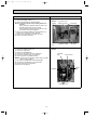
11-3. TRUBLE CRITERION OF MAIN PARTS
MUCFH-GA35VB
MUCFH-GA50VB
Part name
Defrost
thermistor (RT61)
MUCFH-GA60VB
Figure
Check method and criterion
Measure the resistance with a tester.
(Part temperature -10°C ~ 40°C)
Normal
Abnormal
5kΩ ~ 60kΩ
Open or short-circuit
Compressor
(MC)
INNER
PROTECTOR
MUCFH-GA35VB
155i 5: OPEN
90i10: CLOSE
MUCFH-GA50VB
/GA60VB
Measure the resistance between the terminals with a tester.
(Part temperature -10°C ~ 40°C)
WHT C
P
Normal
Color of lead
wire
MUCFH-GA35VB MUCFH-GA50VB MUCFH-GA60VB
C-R
2.46 ~ 3.01Ω
1.05 ~ 1.30Ω
0.84 ~ 1.04Ω
C-S
2.96 ~ 3.63Ω
2.38 ~ 2.92Ω
1.82 ~ 2.24Ω
Abnormal
AUX. MAIN
S
R
RED
Open or
short-circuit
BLK
160i 5: OPEN
90i10: CLOSE
MUCFH-GA35VB
MAIN
AUX.
Outdoor fan
motor
(MF)
MUCFH-GA35VB
INNER FUSE
145i2: CUT OFF
MUCFH-GA50VB
/GA60VB
INNER
PROTECTOR
145i 8: OPEN
( 88i15: CLOSEw)
FUSE
Measure the resistance between the terminals with a tester.
(Part temperature -10°C ~ 40°C)
Normal
Color of lead
wire
MUCFH-GA35VB MUCFH-GA50VB MUCFH-GA60VB
WHT-BLK
191 ~ 231 Ω
70 ~ 86 Ω
61 ~ 74 Ω
BLK-RED
272 ~ 330 Ω
74 ~ 89 Ω
83 ~ 100 Ω
BLK-YLW
BLK
RED WHT
MUCFH-GA50VB
Abnormal
MAIN
AUX
P
Open or
short-circuit
BLK
REDORN WHT
MUCFH-GA60VB
YLW-RED
MAIN
AUX
P
BLK
RED ORN WHT
Measure the resistance using a tester. (Part temperature -10°C ~ 40°C)
R.V. coil
(21S4)
Normal
Abnormal
1.94 kΩ ~ 2.39 kΩ
Open or short-circuit
w Reference value
P : INNER PROTECTOR
27
OB381A--1.qxp
10.5.25 9:29 AM
Page 28
11-4. TROUBLESHOOTING FLOW
Compressor and/or outdoor fan motor doesn’t operate.
A Check of outdoor unit
MUCFH-GA35VB
MUCFH-GA50VB
Operate the unit in COOL or HEAT mode by pressing the EMERGENCY OPERATION switch.
3-minute time delay works.
Test run operation operates for 30 minutes.
Compressor
doesn't operate.
Rectify the indoor and
outdoor connecting wire.
No
Is there 5V DC between J205 + –J101 – on
the deicer P.C. board? w
Yes
Is there 230V AC between 3 on the
compressor contactor (52C) and N
on the outdoor terminal block (TB1)?
No
Is there 230V AC between 4 on the
compressor contactor (52C) and
TAB20 on the deicer P.C. board? w
Yes
Replace the
Replace the
deicer P.C.
deicer P.C. board.
board.
No
No
Is there 230V AC between L–N on
the outdoor terminal block (TB1)?
Yes
Rectify the connecting wire.
Yes
Check the compressor and compressor
capacitor. Refer to 11-3.
Rectify the indoor and
outdoor connecting wire.
Outdoor fan motor
doesn't operate.
No
Is there 5V DC between J205 + –J101 – on
the deicer P.C. board? w
Yes
Check the outdoor fan motor.
Refer to 11-3.
No
Is there 230V AC between 4 on the
compressor contactor (52C) and
TAB 20 on the deicer P.C. board? w
Yes
Replace the
deicer P.C. board.
No
Is there 230V AC between L–N on
the outdoor terminal block (TB1)?
Yes
Rectify the connecting wire.
w Refer to 11-5.
28
OB381A--1.qxp
10.5.25 9:29 AM
Page 29
Compressor and/or outdoor fan motor doesn’t operate.
A Check of outdoor unit
MUCFH-GA60VB
Start
Operate the unit in COOL or HEAT mode by pressing the
EMERGENCY OPERATION switch.
3-minute time delay works.
Test run operation operates for 30 minutes.
Compressor
doesn't operate.
Is there 5V DC between
No
J101 + - J401 on the deicer
P.C. board? w1
Yes
Is there 230V AC between
CN730 1-3 on the deicer
P.C. board? w1
Yes
No
Make the connection
of wiring correct.
Replace the
deicer P.C. board.
Is there 230V AC between
A1-A2 on the compressor
contactor(52C)?
No
Replace the
deicer P.C. board.
Yes
Is there 230V AC between
No
4 on the compressor
contactor(52C) and N on the
outdoor terminal block?
Yes
Is there 230V AC between
No
3 on the compressor
contactor(52C) and N on the
outdoor terminal block?
Make the connection
of wiring correct.
Yes
Check the compressor.
Refer to 11-3..
Replace the compressor
contactor(52C).
Outdoor fan motor
doesn't operate.
Is there 5V DC between
No
J101 + - J401 on the deicer
P.C. board? w1
Yes
Is there 230V AC between
CN730 1-3 on the deicer
P.C. board? w1
Yes
No
Make the connection
of wiring correct.
Replace the
deicer P.C. board.
Is there 230V AC between
CN711 1-3 or 2-3 on the
deicer P.C. board? w1
No
Replace the
deicer P.C. board.
Yes
w1 Refer to 11-5.
Check the outdoor fan
motor. Refer to 11-3.
29
OB381A--1.qxp
10.5.25 9:29 AM
Page 30
When OPERATION INDICATOR lamp flashes ON and OFF in every 0.5-second.
Outdoor unit does not operate.
B How to check mis-wiring and serial signal error (when outdoor unit does not work)
Start
Yes
Make them sure.
Is this mis-wiring, poor contact,
or disconnection of wire?
No
1. Turn OFF the power supply(indoor/outdoor unit) and disconnect indoor and outdoor connecting wire on indoor side.
2. Short-circuit between indoor terminal block N and 3.
3. Turn ON the power supply(indoor unit) and press once EMERGENCY OPERATION switch.
Is there 20V DC between both ends of
R132 on indoor electronic control P.C.
board ?
( By tester, the stylus is between 0 ~ 20V. )
No
Replace the indoor electronic
control P.C. board.
Yes
•Turn OFF the power supply(indoor unit).
•Connect ON indoor and outdoor connecting wire.
Turn ON the power supply(outdoor unit).
Is there 230V AC between outdoor terminal
block L-N (TB1)?
No
Yes
Check the outdoor power supply,
power supply cord and
connection.
Is there 5V DC between J205 + –J101 - (MUCFH-GA35VB/GA50VB)/
J101 + –J401 - (MUCFH-GA60VB) on the deicer P.C. board?
No
Replace the deicer P.C. board.
Yes
Turn ON the power supply(indoor unit).
During EMERGENCY OPERATION,
is there 10V DC between both ends
of R601?
(By tester, the stylus is between 5 ~10V)
Yes
Replace the deicer P.C. board.
Refer to indoor unit service manual.
30
No
Make the wiring between CN730
on the deicer P.C. board and
outdoor terminal block correct.
OB381A--2.qxp
10.5.25 9:33 AM
Page 31
Compressor and/or outdoor fan motor doesn’t stop.
C Check of outdoor unit
MUCFH-GA35VB
MUCFH-GA50VB
1 Turn OFF the power supply.
2 After 30 seconds, turn ON the power supply again.
3 Operate the unit in COOL or HEAT mode by
pressing the EMERGENCY OPERATION switch.
4 Operate the unit for 1 minute or more and stop it by
pressing the EMERGENCY OPERATION switch again.
No
Does compressor stop?
Yes
Is there 230V AC between 3 on the
compressor contactor (52C) and N on the
outdoor terminal block (TB1)?
Yes
OK
No
Rectify the connecting wire.
Replace the
deicer P.C. board.
No
Replace the
deicer P.C. board.
Does outdoor fan motor stop?
Yes
OK
MUCFH-GA60VB
1 Turn OFF the power supply.
2 After 30 seconds, turn ON the power supply again.
3 Operate the unit in COOL or HEAT mode by
pressing the EMERGENCY OPERATION switch.
4 Operate the unit for 1 minute or more and stop it by
pressing the EMERGENCY OPERATION switch again.
After 30 seconds,
does compressor stop?
No
Yes
OK
After 30 seconds, does
outdoor fan motor stop?
Is there 230V AC between
A1-A2 on the compressor
contactor(52C)?
Yes
Is there 230V AC between
4 on the compressor
contactor and N on the
outdoor terminal block?
Yes
No
Replace the
deicer P.C. board.
No
Replace the compressor
contactor(52C).
Replace the
deicer P.C. board.
Yes
OK
Unit operates HEAT mode even if it is set to COOL mode.
D Check of R.V. coil
w First, measure the resistance of R.V. coil to confirm it is disconnected or is not short-circuit.
Disconnect the TAB52 on the deicer P.C. board. (MUCFH-GA60VB)
Turn ON the power supply and operate the indoor unit in COOL mode
by pressing the EMERGENCY OPERATION switch.
After 3 minutes, does the unit
operate in HEAT mode?
No
OK
Yes
Is there 230V AC between
No
CN7211 – 2 (MUCFH-GA35VB/GA50VB)/
CN7211 – 3 (MUCFH-GA60VB)
on the deicer P.C. board?
Yes
Replace the
deicer P.C. board.
31
Replace the R.V. coil.
No
Make the connection
of wiring correct.
OB381A--2.qxp
10.5.25 9:33 AM
Page 32
Unit operates COOL mode even if it is set to HEAT mode.
D Check of R.V. coil
w First, measure the resistance of R.V. coil to confirm it is disconnected or is not short-circuit.
Disconnect the TAB52 on the deicer P.C. board. (MUCFH-GA60VB)
Turn ON the power supply and operate the indoor unit in HEAT mode
by pressing the EMERGENCY OPERATION switch.
After 3 minutes, does the unit
operate in COOL mode?
No
OK
Yes
Is there 230V AC between
CN7211 – 2 (MUCFH-GA35VB/GA50VB)/
CN7211 – 3 (MUCFH-GA60VB)
on the deicer P.C. board?
No
Replace the
deicer P.C. board
Yes
Replace the R.V. coil.
When OPERATION INDICATOR lamp flashes 6-time.
Thermistors in the outdoor unit are abnormal.
E Check of outdoor thermistor
w Disconnect the connectors CN661 from the deicer P.C. board.
(Check the characteristics of each thermistor.)
Replace the deicer P.C.
board.
Defrost thermistor(RT61)
Turn OFF the
power supply.
Measure
resistance
between CN 661
1 and 2.
Does the resistance
Yes
of thermistor have
the characteristics
on 11-5.?
No
Reconnect CN661.
Turn ON the power
supply and press
the EMERGENCY
OPERATION
switch.
No
Does the unit operate
10 minutes or more?
Yes
OK W1.
Replace the
thermistor.
W1. It is thought defective contact of the connector.
32
OB381A--2.qxp
10.5.25 9:33 AM
Page 33
11-5. TEST POINT DIAGRAM AND VOLTAGE
Power supply input
230V AC
}
}
CN711
CN721
Outdoor fan motor R.V. coil
230V AC
230V AC
}
MUCFH-GA35VB
MUCFH-GA50VB
Outdoor deicer P.C. board
NR61
Varistor
F61
Fuse
2A/250V
+
--
}
R601
5~10V DC
Defrost interval time
short pin
(JPDS, JPSG)
(Refer to 10-1.)
wire for
} Jumper
change in defrost
setting
(JRF,JRG)
(Refer to 10-2.)
}
5V DC
J205 +
J101 --
(Refer to
11-4.A or
B.)
12V DC
J204 +
J101 --
33
CN661 1-2
Defrost thermistor RT61 (Refer to 11-4.E.)
OB381A--2.qxp
10.5.25 9:33 AM
Page 34
MUCFH-GA60VB
Outdoor deicer P.C. board
Defrost thermistor (RT61)
100
Resistance(k")
90
80
70
60
50
40
30
20
10
0
-20 -10 0 10 20 30 40
Temperature(:)
CN661 1-2
Defrost thermistor (RT61)
(Refer to 11-4.E.)
Fan motor
(CN711) Varistor
(NR62)
230V
coil
} R.V.
(CN721)
230V
Defrost
interval
time short
pin(JPG1,
R871)
(Refer to
10-1.)
+
} 12V DC
Fuse (F61)
3.15A / 250V
Varistor
(NR61)
Power supply input
CN7301-3
230V AC
(Refer to
11-4.A.)
R601
10V DC
+
(Refer to
11-4.B.)
J101 +
5V
DC
J401
(Refer to
11-4.A or
B.)
}
}
}
Jumper wire for
change in defrost
setting (JRF, JRG)
(Refer to 10-2.)
34
OB381A--2.qxp
10.5.25 9:33 AM
12
Page 35
DISASSEMBLY INSTRUCTIONS
<"Terminal with locking mechanism" Detaching points>
The terminal which has the locking mechanism can be detached as shown below.
There are two types ( Refer to (1) and (2)) of the terminal with locking mechanism.
The terminal without locking mechanism can be detached by pulling it out.
Check the shape of the terminal before detaching.
(1) Slide the sleeve and check if there is a locking lever or not.
(2) The terminal with this connector has the locking
mechanism.
Sleeve
Locking lever
1Slide the sleeve.
2Pull the terminal while
pushing the locking
lever.
1Hold the sleeve, and
pull out the terminal
slowly.
Connector
12-1. MUCFH-GA35VB
OPERATING PROCEDURE
PHOTOS
1. Removing the cabinet
(1)
(2)
(3)
(4)
(5)
Remove the
Remove the
Remove the
Remove the
Remove the
the insides.
(6) Remove the
(7) Remove the
screws of the top panel.
screw of the service panel.
screws of the cabinet.
screws of the front panel and motor support.
service panel, and remove the screw from
Photo 1
Screws of the front panel and motor support
top panel.
cabinet.
Screws
of the
cabinet
Photo 3
Screws of the
service panel
Screws of the cabinet
Screws of
the top panel
Photo 2
Service
panel
Screw of the
top panel
Screws of the
cabinet
35
OB381A--2.qxp
10.5.25 9:33 AM
Page 36
OPERATING PROCEDURE
PHOTOS
2. Removing the deicer P.C. board
Photo 4
(1) Remove the service panel and the cabinet.
(2) Disconnect all the connectors and the terminals on the
deicer P.C. board.
(3) Remove the deicer P.C. board.
Deicer
P.C. board
Relay panel
Screw
3. Removing the propeller and the outdoor fan motor
(1) Remove the cabinet. (Refer to 1.)
(2) Remove the propeller nut.
(3) Remove the propeller.
NOTE : Loose the propeller in the rotating direction for
removal.
When attaching the propeller, align the mark on the
propeller and the motor shaft cut section.
Set the propeller in position by using the cut on the
shaft and the mark on the propeller.
(4) Remove lead clamps and disconnect the outdoor fan motor
connector.
(5) Remove screws fixing the fan motor.
(6) Remove the outdoor fan motor.
Screws
Photo 5
Lead clamps
Screws of the
outdoor fan motor Hook
Propeller Propeller
nut
Screws of the
outdoor fan motor
36
Terminal
block
Outdoor
fan motor
connector
OB381A--2.qxp
10.5.25 9:33 AM
Page 37
OPERATING PROCEDURE
PHOTOS
4. Removing the compressor
(1)
(2)
(3)
(4)
(5)
Remove the cabinet. (Refer to 1.)
Remove the relay panel.
Remove the soundproof felt.
Remove the terminal cover on the compressor.
Disconnect lead wires from the glass terminal of the compressor.
(6) Recover gas from the refrigerant circuit.
NOTE : Recover gas from the pipes until the pressure gauge
shows 0 kg/cm2 (0 MPa).
(7) Disconnect the welded part of the discharge pipe.
(8) Disconnect the welded part of the suction pipe.
(9) Remove nuts fixing the compressor.
(10) Remove the compressor.
Photo 6
Discharge pipe
Glass
terminal
Compressor
Compressor nuts
37
Suction pipe
Terminal cover
OB381A--2.qxp
10.5.25 9:33 AM
Page 38
12-2. MUCFH-GA50VB
OPERATING PROCEDURE
PHOTOS
1. Removing the cabinet
(1) Remove the screws of the cabinet.
(2) Hold the bottom of the cabinet on both sides and remove
the cabinet.
Photo 1
Photo 2
Screws
of the
cabinet
Service
panel
Screws of
the cabinet
2. Removing the deicer P.C. board
Photo 3
(1) Remove the service panel and the cabinet.
(2) Disconnect all the connectors and the terminals on the
deicer P.C. board.
(3) Remove the deicer P.C. board.
Screw of the
relay panel
Deicer
P.C. board
Relay panel
38
Terminal blocks
Screw of the
relay panel
OB381A--2.qxp
10.5.25 9:33 AM
Page 39
OPERATING PROCEDURE
PHOTOS
3. Removing the propeller and the outdoor fan motor
(1) Remove the cabinet. (Refer to 1.)
(2) Remove the propeller nut and the propeller.
NOTE : Loose the propeller in the rotating direction for
removal.
When attaching the propeller, align the mark on the
propeller and the motor shaft cut section.
Set the propeller in position by using the cut on the
shaft and the mark on the propeller.
(3) Remove the clamp of outdoor fan motor lead wire and
disconnect the outdoor fan motor connector.
(4) Remove the screws fixing the outdoor fan motor.
(5) Remove the outdoor fan motor.
Photo 4
Propeller
Propeller
nut
Set screws of the
outdoor fan motor
Set screws of the
outdoor fan motor
Lead clamps
Outdoor
fan motor
4. Removing the compressor
(1)
(2)
(3)
(4)
(5)
(6)
Remove the cabinet. (Refer to 1.)
Remove the relay panel.
Remove the soundproof felt.
Remove the terminal cover on the compressor.
Disconnect lead wires from the compressor.
Recover gas from the refrigerant circuit.
NOTE : Recover gas from the pipes until the pressure gauge
shows 0 kg/cm2 (0 MPa).
(7) Disconnect the welded part of the discharge pipe.
(8) Disconnect the welded part of the suction pipe.
(9) Remove nuts fixing the compressor.
(10) Remove the compressor.
Photo 5
Discharge
pipe
Terminal cover
Suction
pipe
Compressor
Compressor nuts
39
OB381A--2.qxp
10.5.25 9:34 AM
Page 40
12-3. MUCFH-GA60VB
OPERATING PROCEDURE
PHOTOS
1.Removing the cabinet
Photo 1
(1) Remove the screws of the service panel.
(2) Remove the screws of the top panel.
(3) Remove the screw of the valve cover.
(4) Remove the service panel.
(5) Remove the top panel.
(6) Remove the valve cover.
(7) Remove the screws of the front panel.
(8) Remove the front panel.
(9) Remove the screws of the back panel.
(10) Remove the back panel.
Screw of the top panel
Screws
of the
cabinet
Screws of the cabinet
Photo 3
Photo 2
Screw of the motor support
Screw of the service panel
Screws
of the
top
panel
Screws
of the
back
panel
Screws
of the
front
panel
Screw
of the
valve
cover
Set screws of the back panel
2. Removing the deicer P.C. board
Photo 4
(1) Remove the service panel and the cabinet.
(2) Disconnect all the connectors and the terminals on the
deicer P.C. board.
(3) Remove the deicer P.C. board.
Screws
of the
relay
panel
40
Deicer P.C. board
Terminal
blocks
Screws of the
relay panel
OB381A--2.qxp
10.5.25 9:34 AM
Page 41
PHOTOS
OPERATING PROCEDURE
3. Removing the propeller and the outdoor fan motor
(1) Remove the cabinet. (Refer to 1.)
(2) Remove the propeller nut and the propeller.
NOTE : Loose the propeller in the rotating direction for
removal.
When attaching the propeller, align the mark on the
propeller and the motor shaft cut section.
Set the propeller in position by using the cut on the
shaft and the mark on the propeller.
(3) Remove the clamp of outdoor fan motor lead wire and
disconnect the outdoor fan motor connector.
(4) Remove the screws fixing the outdoor fan motor.
(5) Remove the outdoor fan motor.
Photo 5
Set screws of the
outdoor fan motor
Propeller
nut
Propeller
Set screws of the outdoor fan motor
4. Removing the compressor
Photo 6
(1)
(2)
(3)
(4)
(5)
(6)
Remove the cabinet. (Refer to 1.)
Remove the relay panel.
Remove the soundproof felt.
Remove the terminal cover on the compressor.
Disconnect lead wires from the compressor.
Recover gas from the refrigerant circuit.
NOTE : Recover gas from the pipes until the pressure gauge
shows 0 kg/cm2 (0 MPa).
(7) Disconnect the welded part of the discharge pipe.
(8) Disconnect the welded part of the suction pipe.
(9) Remove nuts fixing the compressor.
(10) Remove the compressor.
Discharge pipe
Suction pipe
Terminal cover
Compressor nuts
41
OB381A--2.qxp
13
10.5.25 9:34 AM
Page 42
PARTS LIST (non-RoHS compliant)
MUCFH-GA35VB
13-1. OUTDOOR UNIT STRUCTURAL PARTS
1
13
12
11
2
3
10
4
42
5
6
7
8
9
OB381A--2.qxp
10.5.25 9:34 AM
Page 43
PARTS LIST (non-RoHS compliant)
MUCFH-GA35VB
13-1. OUTDOOR UNIT STRUCTURAL PARTS
Part numbers that are circled are not shown in the illustration.
No.
1
2
3
4
5
6
7
8
9
10
11
12
13
Part No.
E02
E02
E02
E02
E02
E02
E02
E02
E02
E02
E02
E02
E02
E02
14 E02
E02
15 E02
837
815
815
754
075
832
910
910
931
815
836
442
815
156
726
837
891
630
232
521
900
506
290
661
662
961
245
233
515
297
936
936
936
642
Part name
OUTDOOR HEAT EXCHANGER
CABINET
GRILLE (OUT)
COMPRESSOR
COMPRESSOR RUBBER SET
BASE
STOP VALVE (GAS)
STOP VALVE (LIQUID)
4-WAY VALVE
SERVICE PANEL
BACK PANEL
MOTOR SUPPORT
TOP PANEL
CAPILLARY TUBE
CAPILLARY TUBE
CAPILLARY TUBE
CHECK VALVE
Symbol
in Wiring
Diagram
MC
43
Q'ty/unit
MUCFH-GA35VB1
1
1
1
3
1
1
1
1
1
1
1
1
2
1
1
1
Remarks
E1
RN135VHSHT
3RUBBERS/SET
{12.7
{6.35
{3.0x{1.4x500
{3.0x{1.6x600
{3.0x{1.6x1050
OB381A--2.qxp
10.5.25 9:34 AM
Page 44
PARTS LIST (non-RoHS compliant)
MUCFH-GA35VB
13-3. ACCESSORY
13-2. OUTDOOR UNIT
ELECTRICAL PARTS AND
FUNCTIONAL PARTS
7
8
3
2
1
13
12
6
5
4
13-2. OUTDOOR UNIT ELECTRICAL PARTS AND FUNCTIONAL PARTS
Part numbers that are circled are not shown in the illustration.
No.
1
2
3
4
5
6
7
8
9
10
11
Part name
Part No.
E02
E02
E02
E02
E02
E02
E02
E02
E02
E02
E02
665
672
696
836
890
817
836
699
910
095
820
501
301
353
451
383
374
374
310
490
382
385
PROPELLER
OUTDOOR FAN MOTOR
COMPRESSOR CAPACITOR
DEICER P.C. BOARD
SURGE ABSORBER
TERMINAL BLOCK
TERMINAL BLOCK
DEFROST THERMISTOR
R. V. COIL
FUSE
VARISTOR
Symbol
in Wiring
Diagram
MF
C1
DSAR
TB1
TB2
RT61
21S4
F61
NR61
Q'ty/unit
MUCFH-GA35VB1
1
1
1
1
1
1
1
1
1
1
Remarks
E1
RA6V3330+ /440V AC
3P
2P
250V /2A
13-3. ACCESSORY
12 E02 817 704
13 E02 444 705
1
2
DRAIN SOCKET
DRAIN CAP
44
[33 2PCS/SET
OB381A--2.qxp
10.5.25 9:34 AM
Page 45
PARTS LIST (non-RoHS compliant)
MUCFH-GA50VB
13-4. OUTDOOR UNIT STRUCTURAL PARTS,
ELECTRICAL PARTS AND FUNCTIONAL PARTS
13-5. ACCESSORY
27
19 18
DEFROST THERMISTOR
28
21
20
17
15
1
16
2
14
13
12
11
10
4
3
5
6
7
8
9
13-4. OUTDOOR UNIT STRUCTURAL PARTS, ELECTRICAL PARTS AND FUNCTIONAL PARTS
Part numbers that are circled are not shown in the illustration.
No.
1
2
3
4
5
6
7
8
9
10
11
12
13
14
15
16
17
18
19
20
21
22
23
24
25
26
Part No.
E02
E02
E02
E02
E02
E02
E02
E02
E02
E02
E02
E02
E02
E02
E02
E02
E02
E02
E02
E02
E02
E02
E02
E02
E02
E02
E02
E02
E02
817
817
817
643
141
139
075
817
817
817
820
817
891
888
816
895
820
817
821
820
817
139
746
289
820
095
821
891
820
233
232
521
630
501
515
506
900
290
661
662
245
961
353
301
383
451
374
374
310
009
936
937
937
936
382
490
642
385
Part Name
BACK PANEL
CABINET
GRILLE
OUTDOOR HEAT EXCHANGER
PROPELLER
MOTOR SUPPORT
COMPRESSOR RUBBER SET
COMPRESSOR
BASE
STOP VALVE (GAS)
STOP VALVE (LIQUID)
SERVICE PANEL
4-WAY VALVE
COMPRESSOR CAPACITOR
OUTDOOR FAN MOTOR
SURGE ABSORBER
DEICER P.C. BOARD
TERMINAL BLOCK
TERMINAL BLOCK
DEFROST THERMISTOR
HANDLE
CAPILLARY TUBE
CAPILLARY TUBE
CAPILLARY TUBE
CAPILLARY TUBE
FUSE
R.V. COIL
CHECK VALVE
VARISTOR
Symbol
in Wiring
Diagram
MC
C1
MF
DSAR
TB1
TB2
RT61
F61
21S4
NR61
Q'ty/unit
MUCFH-GA50VB1
1
1
1
1
1
3
1
1
1
1
1
1
1
1
1
1
1
1
1
1
2
1
1
1
1
1
1
1
Remarks
E1
3RUBBERS/SET
RN196VHSHT
{12.7
{ 6.35
40+/440V AC
RA6V50 -
3P
2P
{3.0✕{1.6✕750
{3.0✕{1.6✕650
{3.0✕{1.6✕500
{2.5✕{0.6✕1000
250V / 2A
13-5. ACCESSORY
1
2
1
27 E02 817 704 DRAIN SOCKET
E02 444 705 DRAIN CAP
28
E02 444 706 DRAIN CAP
45
[33 2PCS/SET
[16
OB381A--2.qxp
10.5.25 9:34 AM
Page 46
PARTS LIST (non-RoHS compliant)
MUCFH-GA60VB
13-6. OUTDOOR UNIT STRUCTURAL PARTS, ELECTRICAL PARTS
AND FUNCTIONAL PARTS
27
26 25
24
23
22
21
1
20
19
2
18
3
4
5
6
17
7
9
10
8
11
16
12
13
13-7. ACCESSORY
32
33
46
14
15
OB381A--2.qxp
10.5.25 9:34 AM
Page 47
PARTS LIST (non-RoHS compliant)
MUCFH-GA60VB
13-6. OUTDOOR UNIT STRUCTURAL PARTS, ELECTRICAL PARTS
AND FUNCTIONAL PARTS
Part numbers that are circled are not shown in the illustration.
No.
E02
E02
E02
E02
E02
E02
E02
E02
E02
E02
E02
E02
E02
E02
E02
E02
E02
E02
E02
E02
E02
E02
E07
E02
E02
E02
E02
E02
E02
E02
E02
31
E02
1
2
3
4
5
6
7
8
9
10
11
12
13
14
15
16
17
18
19
20
21
22
23
24
25
26
27
28
29
30
Part Name
Part No.
819
821
892
214
821
819
819
819
891
821
821
527
821
819
821
819
819
890
821
817
895
912
012
889
819
817
726
127
336
891
069
139
297
630
301
501
290
232
009
521
961
490
310
506
900
661
662
650
245
383
374
374
351
451
340
353
233
009
515
382
385
642
936
937
TOP PANEL
OUTDOOR HEAT EXCHANGER
OUTDOOR FAN MOTOR
PROPELLER
BASE
CABINET
HANDLE
FAN GUARD
4-WAY VALVE
R.V. COIL
DEFROST THERMISTOR
COMPRESSOR RUBBER SET
COMPRESSOR
STOP VALVE (GAS)
STOP VALVE (LIQUID)
VALVE COVER
SERVICE PANEL
SURGE ABSORBER
TERMINAL BLOCK
TERMINAL BLOCK
OUTDOOR FAN CAPACITOR
DEICER P.C. BOARD
COMPRESSOR CONTACTOR
COMPRESSOR CAPACITOR
BACK PANEL (OUT)
HANDLE
MOTOR SUPPORT
FUSE
VARISTOR
CHECK VALVE
CAPILLARY TUBE
CAPILLARY TUBE
Symbol
in Wiring
Diagram
MF
21S4
RT61
MC
DSAR
TB2
TB1
C2
52C
C1
F61
NR61
Q'ty/unit
MUCFH-GA60VB 1
1
1
1
1
1
1
1
1
1
1
4
1
1
1
1
1
1
1
1
1
1
1
1
1
1
1
1
1
1
1
1
E1
Remarks
RA6V85-
4RUBBERS/SET
NN29VBAHT
{15.88
{6.35
2P
3P
3.0+/440V AC
55+/440V AC
250V/3.15A
{3.0x{2.0x400
{3.0x{2.0x800
13-7. ACCESSORY
32 E02 817 704 DRAIN SOCKET
33 E02 444 705 DRAIN CAP
1
2
47
[33 2PCS/SET
OB381A--2.qxp
14
10.5.25 9:34 AM
Page 48
RoHS PARTS LIST (RoHS compliant)
MUCFH-GA35VB
14-1. OUTDOOR UNIT STRUCTURAL PARTS
1
13
12
11
2
3
10
4
48
5
6
7
8
9
OB381A--2.qxp
10.5.25 9:34 AM
Page 49
PARTS LIST (non-RoHS compliant)
MUCFH-GA35VB
14-1. OUTDOOR UNIT STRUCTURAL PARTS
No.
1
2
3
4
5
6
7
8
9
10
11
12
13
RoHS
Part numbers that are circled are not shown in the illustration.
G
G
G
G
G
G
G
G
G
G
G
G
G
G
14 G
G
15 G
Part No.
E12
E12
E12
E12
E12
E12
E12
E12
E12
E12
E12
E12
E12
E12
E12
E12
E12
837
815
815
754
075
832
910
910
931
815
836
442
815
156
726
837
891
630
232
521
900
506
290
661
662
961
245
233
515
297
936
936
936
642
Part name
OUTDOOR HEAT EXCHANGER
CABINET
GRILLE(OUT)
COMPRESSOR
COMPRESSOR RUBBER SET
BASE
STOP VALVE (GAS)
STOP VALVE (LIQUID)
4-WAY VALVE
SERVICE PANEL
BACK PANEL
MOTOR SUPPORT
TOP PANEL
CAPILLARY TUBE
CAPILLARY TUBE
CAPILLARY TUBE
CHECK VALVE
Symbol
in Wiring
Diagram
MC
49
Q'ty/unit
MUCFH-GA35VB1
1
1
1
3
1
1
1
1
1
1
1
1
2
1
1
1
Remarks
E1
RN135VHSHT
3RUBBERS/SET
{12.7
{6.35
{3.0x{1.4x500
{3.0x{1.6x600
{3.0x{1.6x1050
OB381A--2.qxp
10.5.25 9:34 AM
Page 50
RoHS PARTS LIST (RoHS compliant)
MUCFH-GA35VB
14-3. ACCESSORY
14-2. OUTDOOR UNIT
ELECTRICAL PARTS AND
FUNCTIONAL PARTS
7
8
2
1
3
13
12
6
5
4
14-2. OUTDOOR UNIT ELECTRICAL PARTS AND FUNCTIONAL PARTS
No.
1
2
3
4
5
6
7
8
9
10
11
RoHS
Part numbers that are circled are not shown in the illustration.
G
G
G
G
G
G
G
G
G
G
G
Part name
Part No.
E12
E12
E12
E12
E12
E12
E12
E12
E12
E12
E12
665
672
900
836
890
817
836
699
910
095
820
501
301
353
451
383
374
374
310
490
382
385
Symbol
in Wiring
Diagram
PROPELLER
OUTDOOR FAN MOTOR
COMPRESSOR CAPACITOR
DEICER P.C. BOARD
SURGE ABSORBER
TERMINAL BLOCK
TERMINAL BLOCK
DEFROST THERMISTOR
R. V. COIL
FUSE
VARISTOR
MF
C1
DSAR
TB1
TB2
RT61
21S4
F61
NR61
Q'ty/unit
MUCFH-GA35VB1
1
1
1
1
1
1
1
1
1
1
Remarks
E1
RA6V3330+ /440V AC
3P
2P
250V /2A
14-3. ACCESSORY
12 G E12 817 704
13 G E12 444 705
1
2
DRAIN SOCKET
DRAIN CAP
50
[33 2PCS/SET
OB381A--2.qxp
10.5.25 9:34 AM
Page 51
RoHS PARTS LIST (RoHS compliant)
MUCFH-GA50VB
14-4. OUTDOOR UNIT STRUCTURAL PARTS,
ELECTRICAL PARTS AND FUNCTIONAL PARTS
14-5. ACCESSORY
27
19 18
DEFROST THERMISTOR
28
21
20
17
15
1
16
2
14
13
12
11
10
4
3
5
6
7
8
9
14-4. OUTDOOR UNIT STRUCTURAL PARTS, ELECTRICAL PARTS AND FUNCTIONAL PARTS
No.
1
2
3
4
5
6
7
8
9
10
11
12
13
14
15
16
17
18
19
20
21
22
23
24
25
26
RoHS
Part numbers that are circled are not shown in the illustration.
G
G
G
G
G
G
G
G
G
G
G
G
G
G
G
G
G
G
G
G
G
G
G
G
G
G
G
G
G
Part No.
E12
E12
E12
E12
E12
E12
E12
E12
E12
E12
E12
E12
E12
E12
E12
E12
E12
E12
E12
E12
E12
E12
E12
E12
E12
E12
E12
E12
E12
817
817
817
643
141
139
075
817
817
817
820
817
891
888
816
895
820
817
821
820
817
139
746
289
820
095
821
891
820
233
232
521
630
501
515
506
900
290
661
662
245
961
353
301
383
451
374
374
310
009
936
937
937
936
382
490
642
385
Part Name
BACK PANEL
CABINET
GRILLE
OUTDOOR HEAT EXCHANGER
PROPELLER
MOTOR SUPPORT
COMPRESSOR RUBBER SET
COMPRESSOR
BASE
STOP VALVE (GAS)
STOP VALVE (LIQUID)
SERVICE PANEL
4-WAY VALVE
COMPRESSOR CAPACITOR
OUTDOOR FAN MOTOR
SURGE ABSORBER
DEICER P.C. BOARD
TERMINAL BLOCK
TERMINAL BLOCK
DEFROST THERMISTOR
HANDLE
CAPILLARY TUBE
CAPILLARY TUBE
CAPILLARY TUBE
CAPILLARY TUBE
FUSE
R.V. COIL
CHECK VALVE
VARISTOR
Symbol
in Wiring
Diagram
MC
C1
MF
DSAR
TB1
TB2
RT61
F61
21S4
NR61
Q'ty/unit
MUCFH-GA50VB1
1
1
1
1
1
3
1
1
1
1
1
1
1
1
1
1
1
1
1
1
2
1
1
1
1
1
1
1
Remarks
E1
3RUBBERS/SET
RN196VHSHT
{12.7
{ 6.35
40+/440V AC
RA6V50 -
3P
2P
{3.0✕{1.6✕750
{3.0✕{1.6✕650
{3.0✕{1.6✕500
{2.5✕{0.6✕1000
250V / 2A
14-5. ACCESSORY
1
2
1
27 G E12 817 704 DRAIN SOCKET
G E12 444 705 DRAIN CAP
28
G E12 444 706 DRAIN CAP
51
[33 2PCS/SET
[16
OB381A--2.qxp
10.5.25 9:34 AM
Page 52
RoHS PARTS LIST (RoHS compliant)
MUCFH-GA60VB
14-6. OUTDOOR UNIT STRUCTURAL PARTS, ELECTRICAL PARTS
AND FUNCTIONAL PARTS
27
26 25
24
23
22
21
1
20
19
2
18
3
4
5
6
17
7
9
10
8
11
16
12
13
14-7. ACCESSORY
32
33
52
14
15
OB381A--2.qxp
10.5.25 9:34 AM
Page 53
RoHS PARTS LIST (RoHS compliant)
MUCFH-GA60VB
14-6. OUTDOOR UNIT STRUCTURAL PARTS, ELECTRICAL PARTS
AND FUNCTIONAL PARTS
No.
RoHS
Part numbers that are circled are not shown in the illustration.
G
G
G
G
G
G
G
G
G
G
G
G
G
G
G
G
G
G
G
G
G
G
G
G
G
G
G
G
G
G
G
31
G
1
2
3
4
5
6
7
8
9
10
11
12
13
14
15
16
17
18
19
20
21
22
23
24
25
26
27
28
29
30
Part Name
Part No.
E12
E12
E12
E12
E12
E12
E12
E12
E12
E12
E12
E12
E12
E12
E12
E12
E12
E12
E12
E12
E12
E12
E17
E12
E12
E12
E12
E12
E12
E12
E12
E12
819
821
892
214
821
819
819
D84
891
821
821
527
821
819
821
819
819
890
821
817
895
912
012
889
819
817
726
A49
336
891
069
139
297
630
301
501
290
232
009
521
961
490
310
506
900
661
662
650
245
383
374
374
351
451
340
353
233
009
515
382
385
642
936
937
TOP PANEL
OUTDOOR HEAT EXCHANGER
OUTDOOR FAN MOTOR
PROPELLER
BASE
CABINET
HANDLE
FAN GUARD
4-WAY VALVE
R.V. COIL
DEFROST THERMISTOR
COMPRESSOR RUBBER SET
COMPRESSOR
STOP VALVE (GAS)
STOP VALVE (LIQUID)
VALVE COVER
SERVICE PANEL
SURGE ABSORBER
TERMINAL BLOCK
TERMINAL BLOCK
OUTDOOR FAN CAPACITOR
DEICER P.C. BOARD
COMPRESSOR CONTACTOR
COMPRESSOR CAPACITOR
BACK PANEL (OUT)
HANDLE
MOTOR SUPPORT
FUSE
VARISTOR
CHECK VALVE
CAPILLARY TUBE
CAPILLARY TUBE
Symbol
in Wiring
Diagram
MF
21S4
RT61
MC
DSAR
TB2
TB1
C2
52C
C1
F61
NR61
Q'ty/unit
MUCFH-GA60VB 1
1
1
1
1
1
1
1
1
1
1
4
1
1
1
1
1
1
1
1
1
1
1
1
1
1
1
1
1
1
1
1
E1
Remarks
RA6V85-
Including ice guard
4RUBBERS/SET
NN29VBAHT
{15.88
{6.35
2P
3P
3.0+/440V AC
55+/440V AC
T3.15AL250V
{3.0x{2.0x400
{3.0x{2.0x800
14-7. ACCESSORY
32 G E12 817 704 DRAIN SOCKET
33 G E12 444 705 DRAIN CAP
1
2
53
[33 2PCS/SET
OB381A--2.qxp
10.5.25 9:34 AM
Page 54
54
OB381A--2.qxp
10.5.25 9:34 AM
Page 55
55
OB381A--2.qxp
10.5.25 9:34 AM
Page 56
HEAD OFFICE: TOKYO BLDG., 2-7-3, MARUNOUCHI, CHIYODA-KU, TOKYO 100-8310, JAPAN
C Copyright 2005 MITSUBISHI ELECTRIC ENGINEERING CO.,LTD
Distributed in Jun 2010. No.OB381 REVISED EDITION-B 5
Distributed in May 2006. No.OB381 REVISED EDITION-A 6
Distributed in Jan. 2005. No.OB381 6
Made in Japan
New publication, effective Jun. 2010
Specifications subject to change without notice.