1
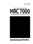
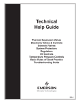
SERVICE MANUAL
FOR
7535, 8534, 8535 SERIES
HEAT PUMPS
TABLE OF CONTENTS
I.
Warnings . . . . . . . . . . . . . . . . . . . . . . . . . . . . . . . . . . . . . . . . . . . . . . . . . . . . . .
3
II.
Unit Specifications . . . . . . . . . . . . . . . . . . . . . . . . . . . . . . . . . . . . . . . . . . . . . .
4
III.
Heat Pump Operation With 7530-716 Or 8530-715 Standard
Ceiling Assemblies . . . . . . . . . . . . . . . . . . . . . . . . . . . . . . . . . . . . . . . . . . . . . .
5
Wall Thermostat Specifications And Heat Pump Operations With
7530-736 Or 8530-735 Ducted Plenums . . . . . . . . . . . . . . . . . . . . . . . . . . . . .
7
V.
Basic Components And Their Functions . . . . . . . . . . . . . . . . . . . . . . . . . . . .
9
VI.
The Heat Pump Refrigeration Cycle . . . . . . . . . . . . . . . . . . . . . . . . . . . . . . . .
11
VII.
General Electrical Operational Information . . . . . . . . . . . . . . . . . . . . . . . . .
12
VIII. Service Problems And Possible Solutions . . . . . . . . . . . . . . . . . . . . . . . . . . .
13
IX.
Individual Electrical Component Checkouts . . . . . . . . . . . . . . . . . . . . . . . .
14
X.
Wiring Diagrams . . . . . . . . . . . . . . . . . . . . . . . . . . . . . . . . . . . . . . . . . . . . . . .
20
IV.
I. WARNINGS
IMPORTANT NOTICE
WARNING - SHOCK HAZARD
These instructions are for the use of qualified individuals
specially trained and experienced in installation of this type
equipment and related system components.
To prevent the possibility of severe personal injury or
equipment damage due to electrical shock, always be sure the
electrical power to the appliance is disconnected.
Installation and service personnel are required by some states
to be licensed. PERSONS NOT QUALIFIED SHALL NOT
SERVICE THIS EQUIPMENT.
CAREFULLY FOLLOW ALL INSTRUCTIONS AND
WARNINGS IN THIS BOOKLET TO AVOID DAMAGE TO
THE EQUIPMENT, PERSONAL INJURY OR FIRE.
WARNING
NOTE
Improper installation may damage equipment, can create a
hazard and will void the warranty.
The words “Shall” or “Must” indicate a
requirement which is essential to
satisfactory and safe product performance.
The use of components not tested in combination with these
units will void the warranty, may make the equipment in
violation of state codes, may create a hazard and may ruin the
equipment.
The words “Should” or “May” indicate a
recommendation which is not essential
and not required, but which may be useful
or helpful.
UNIT MODEL NUMBER BREAKDOWN
3
II. UNIT SPECIFICATIONS
Cooling Capacity
Heating Capacity In Heat Pump Mode
Heating Capacity Of Electric Heat Strip
15,000 (Nominal BTUH)
12,700 (Nominal BTUH at 47°F)
5,600 BTUH
Electrical Rating
115 VAC, 60 HZ, 1 Phase
Compressor Cooling Full Load
Fan Motor Amps At A.R.I.
Total Standard Condition
12.4
Low 2.8
15.2
High 3.3
15.7
Feature Heating Equipment Amps
15.4
Running Watts (Cooling) A.R.I. Standard Condition
(80°F. DB/67°F. WB Indoor, 95°F. DB Outdoor at 103.5 VAC)
1710
Running Watts (Cooling) A.R.I. Maximum Condition
(95°F. DB/71°F. WB Indoor, 115°F. DB Outdoor At 103.5 VAC)
2150
Running Watts (Heating) 47°F. Outdoor Temperature
1675
Compressor Locked Rotor Amps
71.0
Compressor Ohm Ratings (Approx.)
C = Common, S = Start, R = Run
(C-S) 1.8
Thermostat Temperature Range
Cooling 55°F
Metering Device
(C-R) .5
Heating 90°F
Capillary Tube
Refrigerant Charge
20.00 oz.
Evaporator Air Delivery
340 CFM - High
Installed Weight
110 lbs.
Use time delay fuse or circuit breaker (U.L. H.A.C.R. Type C.S.A.) rated at 20 amps.
Supply wires 12 AWG minimum (copper).
4
III. HEAT PUMP OPERATION WITH 7530-716 OR 8530-715
STANDARD CEILING ASSEMBLIES
If your RV air conditioner is operated from the control panel
located in the ceiling assembly, then there are three controls
on the ceiling assembly that help you control the air
conditioner. They are as follows:
A.
The Selector Switch – The selector switch determines
which mode of operation the heat pump will be in. By
rotating the selector switch, the operator can obtain
any system function desired. System functions vary
depending upon options of both the roof top unit
and ceiling assembly. Figures 1 and 2 show selector
switch location and available functions.
FIGURE 1
The “Operation” section explains the operational
characteristics of each mode of operation.
B.
The Thermostat (Temperature Control) – The
thermostat regulates the “ON” and “OFF”
temperature setting at which the compressor will
operate (See Figures 1 and 2).
C.
Louvers – The louvers are located at both ends of the
ceiling assembly shroud and are used in directing the
discharge air from the unit.
CEILING ASSEMBLY STICKER
FIGURE 2
OPERATION
I.
For Cooling Operation
A.
Turn the selector switch to the “LOW COOL” or
“HIGH COOL” position.
B.
C.
II.
Operation During Cooler Nights (Cooling
Operation)
It is important, when the outdoor temperature drops in the
evening or during the night to below 75°F, that the thermostat
(temperature control) be set at a midpoint between “Warmer”
and “Cooler”. If the setting is at “cooler”, the cooler
(evaporator) coil may become iced-up and stop cooling.
During the day, when the temperatures have risen above 75°F,
reset the thermostat switch to the desired setting.
Rotate the thermostat (temperature control) to the
position that is the most comfortable to you. The
thermostat will turn the compressor on when the
temperature of the air entering the air conditioner
rises a few degrees above the setting you have
selected. When the temperature of the air entering
the air conditioner drops below the selected setting,
the thermostat will turn the compressor off. The air
conditioner, while in the cooling mode, will continue
to cycle the compressor on and off in the above
mentioned fashion until the selector switch is turned
to another mode of operation.
NOTE
Should icing-up occur, it is necessary to let the cooling
(evaporator) coil defrost before normal cooling operation is
resumed. During this time, operate the unit in the “HIGH
FAN” position with the system at maximum air flow. When
increased or full air flow is observed, the cooling coil should
be clear of ice.
Position the louvers to the desired direction the
discharge air is to flow.
III.
Short Cycling
When an air conditioner is in operation, its compressor
circulates refrigerant under high pressure. Once off, it will take
two to three minutes for this high pressure to equalize.
5
the vehicle for more efficient circulation and faster
warm-up. Although the air temperature is lower with
the louvers fully opened, the heating capacity is still
the same.
The air conditioning compressor is unable to start against high
pressure. Therefore, once the air conditioner is turned off, it is
important to leave it off for two to three minutes before
restarting.
Short cycling the compressor (or starting it before pressures
have equalized), will in some instances, kick the circuit breaker
or overload.
IV.
For Heating Operation
A.
Turn the selector switch to the “HIGH HEAT”
position. At “HIGH HEAT”, the fan operates on high
speed with heat output at maximum.
B.
Rotate the thermostat (temperature control) switch to
the position that is the most comfortable to you. The
thermostat will turn the compressor/heater on when
the temperature of the air entering the unit drops
below this setting a few degrees, and automatically
turns off when the temperature of the air entering the
unit rises a few degrees above this setting. The
compressor/heater will continue to cycle on and off in
this fashion until the selector switch is turned to
another mode of operation.
C.
NOTE
The heat pump will operate on reverse
refrigerant cycle while heating at outdoor
temperatures above approximately 40 degrees F.
When the outdoor temperature is below
approximately 40 degrees F, the
heat pump compressor will shut down to
prevent outdoor coil freeze-up. At this
time, the auxiliary electric resistance
heater will be utilized to take the chill out
of the indoor air. The electric resistance
heater is not a substitute for a furnace at
these low outdoor temperatures.
Position the louvers to the desired direction the
discharge air is to flow.
V.
For Air Circulation Only
A.
Turn the selector switch to “LOW FAN” or for
maximum air flow, to “HIGH FAN”.
D.
Position the louvers to the desired direction the
discharge air is to flow.
NOTE
Discharge air temperature can be controlled to some
extent by opening or closing the louvers.
When the selector switch is in “LOW
FAN” or “HIGH FAN” position, the
blower motor will operate continuously.
When the louvers are closed, the warmest localized
discharge air is achieved. Fully opened louvers will
throw the warm discharge air to the back and front of
6
IV. WALL THERMOSTAT SPECIFICATIONS AND
HEAT PUMP OPERATIONS WITH
7530-736 or 8530-735 DUCTED PLENUMS
WALL THERMOSTAT SPECIFICATIONS
SET TEMP. RANGE:
55° TO 90°F.
ACCURACY:
± 2% OF SET TEMPERATURE
SAMPLING RATE:
CONTINUOUS
POWER SOURCE:
9 TO 15 VDC UNREGULATED, UNFILTERED
OPERATING TEMPERATURE:
-10° TO +55°C.
CONTROL MODE:
1 STAGE COOL - ON/OFF CONTROL WITH 3 MINUTE DELAY
BETWEEN CYCLES
OUTPUT LOAD:
SAFEGUARDS:
40 mA MINIMUM TO 1.2 AMP MAXIMUM TOTAL LOAD
*
*
*
*
15 KV E.S.D. TO EXPOSED PLASTIC PARTS
REVERSE POLARITY PROTECTION ON R+ TERMINAL
SPIKE PROTECTION TO 400 VDC ON R+ TERMINAL
CONFORMAL COATING ON P.C. BOARD PROTECTION FROM MOISTURE
SUB-BASE SPECIFICATIONS
1.
2.
3.
7330*3351 THERMOSTAT MUST ASSEMBLE SECURELY TO THE SUB-BASE.
WIRES ARE 18 GA. STRANDED COPPER WITH 1/64 MIN. THICK AT INSULATION EXTENDING FROM BACK OF PART
7 INCHES, ENDS STRIPPED BACK 1/2" AND TERMINATED WITH WIRE NUTS.
SNAP DISC SWITCH CLOSES AT 45 ±5°F AND OPENS AT 60 ±3°F.
Sub-base
This thermostat is equipped with
a replaceable 2 amp fuse
located on the back of the
thermostat body.
Thermostat Body
7
OPERATION
The charts below show the system functions. After the entire air conditioning
system (and furnace system) is installed, check each position function.
All cooling functions controlling to setpoint have a short cycle protection time delay of 3 minutes.
There will be no delay if the cycle OFF time exceeds 3 minutes.
8
V. BASIC COMPONENTS AND THEIR FUNCTIONS
HEAT PUMP REFRIGERATION
SYSTEM DIAGRAM
9
1.
Indoor Coil (Cooling Mode)
condenser entering air.
The purpose of the finned evaporator coil is to transfer the
heat from the warm and moist indoor air to the cold low
pressure refrigerant.
As the refrigerant passes through the first few tubes of the
condenser, its temperature will be lowered or it will be desuperheated. After the refrigerant is de-superheated, it will
begin to condense or change from a vapor to a liquid and will
remain at a nearly constant temperature throughout almost all
of the remainder of the coil. This temperature is called the
condensing temperature or high side saturation temperature
and will always be higher than the condenser entering air
temperature.
As the heat leaves the air, the air temperature drops and some
of the moisture in the air condenses from a vapor to a liquid.
The liquid water (condensate) is drained onto the roof of the
recreational vehicle. As the heat enters the refrigerant in the
evaporator, it causes the refrigerant to evaporate (change from
a liquid to a vapor).
Near the bottom of the condenser, the refrigerant will all be
condensed to a liquid and from there on, its temperature will
drop to more nearly the temperature of the outdoor air. After
the temperature of the refrigerant drops below condensing or
saturation temperature, we call its condition sub-cooled liquid.
The refrigerant remains at nearly constant temperature (called
evaporator temperature or low side saturation temperature) in
the evaporator since there are both liquid and vapor together.
However, near the outlet of the evaporator coil, all of the liquid
has boiled (evaporated) away and from there on, the
temperature of the vapor rises (the vapor becomes
superheated). It is necessary that the vapor become
superheated because it is headed down the suction line to the
compressor, and the compressor can only pump superheated
vapor. Any vapor (which might be present if the vapor were
not superheated) could cause serious mechanical damage to
the compressor.
2.
During all of the three processes in the condenser (desuperheating, condensing, sub-cooling), the refrigerant gives
up heat; but most of the heat is given up during the
condensing process.
5.
The reversing valves main function is to reverse the flow of
refrigerant. Internally, it is composed of two pistons on a
sliding block or cylinder with two openings. The operation of
the piston block is controlled by a solenoid valve. The
solenoid valve controls the flow of the refrigerant, which
produces a pressure difference in the valve itself. When the
solenoid valve is energized, it is in the heating mode. When it
is de-energized, it is in the cooling mode.
Suction Line
The suction line is the copper tube which carries the
superheated vapor refrigerant from the evaporator to the
compressor.
3.
Compressor
The compressor is called a hermetic compressor which means
it is completed sealed (welded together). It is, therefore, not
internally field serviceable. Inside the compressor housing is
basically:
a)
an electric motor which drives the compressor,
b)
a pump which is designed to pump superheated
vapor,
c)
a supply of special refrigerant oil. A small portion of
the oil will circulate out through the system with the
refrigerant, but will constantly return to the
compressor with the refrigerant, so the compressor
will not run out of oil.
4.
Reversing Valve
6.
Discharge Line
The discharge line carries the refrigerant out of the compressor
and to the reversing valve. The reversing valve then
distributes this refrigerant to the outdoor coil during the
cooling mode, and to the indoor coil in the heating mode.
Remember that as the refrigerant entered the compressor, it
was superheated vapor. As the compressor works on the
refrigerant, it adds more heat and also compresses the
refrigerant into a smaller space. The refrigerant, therefore,
leaves the compressor highly superheated - so if the discharge
line is hot to the touch (burns), don’t be surprised - it should
be.
7.
Outdoor Coil (Cooling Mode)
By-Flow Restrictor
The by-flow restrictor is the metering device for the heat
pump. The restrictor is made up of two orifices positioned
back to back. There is a space between the orifices. As the
system is either in the cooling or heating mode, it forces one of
the orifices to seat at one of the tapered ends and force the
other to break its seal. Refrigerant goes around one orifice and
through the other, establishing the pressure drop. The orifices
The purpose of the finned condenser coil is to transfer heat
from the high pressure refrigerant to the warm outdoor air. As
the outdoor air passes over the coil, the heat transfer will
cause the air temperature to rise. Thus the condenser
discharge air will be several degrees warmer than the
10
are different sizes to accommodate for the difference in the
condenser and evaporator sizes.
8.
RAISED TO A HIGH TEMPERATURE IN THE PRESENCE OF
WATER (WHICH ALWAYS EXISTS IN THE
ATMOSPHERE), IT DEFINITELY DOES BECOME A TOXIC
GAS by changing from virtually harmless R-22 to phosgene
and hydrofluoric acids. So, if R-22 in the air is exposed to a
welding or soldering torch flame, burning water heater burner,
burning furnace burner, etc., be sure to avoid breathing it.
High and Low Sides
It is customary for air conditioning technicians to use the
terms high side and low side. In doing so, we refer to the parts
of the refrigerant circuit which, when the system is running,
contains high pressure (high side) and low pressure (low side).
The high side of the system exists from the discharge port of
the compressor to the metering device. The low side is from
the metering device to the compressor cylinders. The dividing
points then are the metering device and the compressor
cylinders.
The temperature at which R-22 changes to toxic gases and
acids varies with the amount or concentration of water
present, i.e. the greater the concentration of water, the lower
the temperature and vise versa. High temperatures normally
exist inside a refrigerant circuit, so we must keep the circuit as
absolutely dry as possible to prevent the formation of
destructive acids.
The high side pressure is also referred to as heat pressure or
condensing pressure, and the low side pressure is also
referred to as suction pressure or evaporator pressure.
Liquid R-22 in the atmosphere will always be about -41
degrees. Therefore, always wear safety glasses when working
with R-22.
It is impossible to state the exact pressures that will exist in the
high side or low side because those pressures will both vary
with different temperature and humidity conditions both inside
and outside the recreational vehicle.
Again, unburned R-22 is not a deadly gas. By using
reasonable safety precautions, the service technician will not
be hurt.
9.
In addition to being almost non-toxic, R-22 is non-flammable,
non-corrosive and miscible (mixable) with oil. It also has a
high latent heat value. This means that it must absorb a large
amount of heat per pound to vaporize or change from a liquid
to a vapor, and it must give up a large amount of heat per
pound to condense or change from a vapor to a liquid.
Refrigerant Charge
The system covered by this service manual all use a refrigerant
called monochlorodifluoromethane (better known as R-22).
We know that R-22 is not a deadly gas because many of us
have breathed it several times and are still living. But, no one
has said that R-22 is completely safe to breathe. A wise
service technician will always keep a work space well
ventilated if R-22 can escape into the air. IF R-22 IS
VI. THE HEAT PUMP
REFRIGERATION CYCLE
The Heat Pump is a refrigeration system like any other
refrigeration system, that heat transfers from one place to
another by the change in state of a liquid. The Heat Pump can
reverse the action or direction of heat transfers. For summer
cooling, it can remove heat from occupied areas and dispose
of the heat into outside air. For any time heat is needed, it
reverses the action with a reversing valve and will
also remove heat from the outside air source and supply heat
to the occupied area. We re-label the coils as indoor and
outdoor as they are now dual purpose, depending on the
usage desired. The outdoor coil is the condenser in the
cooling cycle and the evaporator in the heating cycle. The
indoor coil is the evaporator coil in the cooling cycle and the
condenser coil in the heating cycle.
11
VII. GENERAL ELECTRICAL OPERATIONAL
INFORMATION
HEAT PUMP ELECTRICAL OPERATION
7530-716 or 8530-715 STANDARD CEILING ASSEMBLIES
All air conditioning functions operate the same as a standard
air conditioner. While in the heating mode with the selector
switch in the High Heat position, the #3 terminal will energize
the reversing valve and the compressor. At the same time, the
#1 terminal will energize high speed on the fan motor. The
refrigeration cooling cycle is now reversed and the air
conditioner is now heating running on high speed fan.
This heating element will continue to run until the freeze
switch resets allowing the operation of the heat pump. At no
time will you have the heat pump and the electric heat strip on
at the same time.
NOTE
The heat pump should be considered
a cooling unit which also provides
heat at outdoor temperatures above
freezing. This unit will shut down at
low ambient conditions that would
cause outdoor coil freeze-up,
approximately 40 degrees.
The freeze switch or outdoor thermostat located on the
condenser coil opens at 18° (± 6°) actual coil temperature, not
ambient temperature. When this switch opens, the
compressor shuts off. The reversing valve remains in the
heating position and the fan continues to run on high speed.
When the compressor shuts off, the freeze switch will also
energize a 5600 BTU electric heating element.
HEAT PUMP ELECTRICAL OPERATION WITH
7530-736 OR 8530-735 DUCTED CEILING ASSEMBLIES
All air conditioning functions operate the same as a standard
air conditioner. While in the heating mode with the wall
thermostat in the electric heating position, the white wire (or
the “W” terminal) will energize the reversing valve relay in the
ceiling assembly. At the same time, it will energize both the
compressor relay terminal “Y” and high speed fan relay
terminal “GH” through blocking diodes on the terminal board.
Hence, the refrigeration cooling cycle is now reversed and the
air conditioner is now heating and running on high speed fan.
and the fan continues to run on high speed as long as the wall
thermostat is still calling for electric heat. When the
compressor shuts off, the freeze switch will also energize a
5600 BTU electric heating element.
This heating element will continue to run until the wall
thermostat is satisfied or until the freeze switch resets allowing
the operation of the heat pump. At no time will you have the
heat pump and the electric heat strip on at the same time.
Should conditions exist where neither the heat pump nor the
electric heating element are able to meet the demand for heat,
the thermostat will default to gas heat at an indoor ambient
temperature of 45°.
The blocking diode located on the terminal board just ahead of
the “Y” terminal prevents 12 VDC (+) feedback to the cooling
fan circuit while in the heating mode. Without this, someone
could put the fan switch on the thermostat in the low position,
and energize both high and low speed fan operations at the
same time.
NOTE
The electric heat strip or heat pump will
also continue to operate congruently
during this period. The gas heat default
will terminate at 60° (± 3°).
The freeze switch or outdoor thermostat located on the
condenser coil opens at 18° (± 6°) actual coil temperature, not
ambient temperature. When this switch opens the compressor
shuts off. The reversing valve remains in the heating position
7330-3401 THERMOSTAT SUB-BASE OPERATION
The RVP wall thermostat sub-base part #7330-3401 will give
the customer the option to choose between electric or gas
furnace operation. This sub-base may be used with all heat
pump ceiling plenums.
Neither the electric heating strip or the heat pump were
intended to replace the gas furnace, and at some point, the
capacity of either one of these will not be sufficient to keep up
with the heating load required. It will ultimately be up to the
12
retail customer to choose between electric or gas heating to
achieve his or her desired comfort level.
NOTE
The electric heat strip or heat pump will
also continue to operate congruently
during this period. The gas heat default
will terminate at 60° (± 3°).
The thermostat sub-base combination will operate normally in
either the electric or gas heating positions and will cycle on
and off at the setpoints. Should the electric heat strip or heat
pump not be able to keep up with the demand for heating, the
sub-base has a built-in snap disc switch which will
automatically default to gas heat when the temperature inside
drops below 45°F (± 5°), even if the electric heat position is
chosen. This happens for safety purposes to prevent the
vehicle from becoming too cool or possibly freezing when the
customer is not home to monitor his heating system.
VIII. SERVICE PROBLEMS AND POSSIBLE SOLUTIONS
SERVICE PROBLEMS WITH THE HEAT PUMP AND THE
7530-736 OR 8530-735 DUCTED CEILING ASSEMBLY AND WALL THERMOSTAT
The following list of service problems covers only some of the
more common problems which may occur and lists only the
more probable causes.
In many instances, it will be necessary to use the wiring
diagram in this guide to checkout the electrical circuits step by
step, starting at the power source.
13
SERVICE PROBLEMS WITH THE HEAT PUMP
AND THE 7530-716 OR 8530-715 STANDARD CEILING ASSEMBLIES
The following list of service problems covers only some of the
more common problems which may occur and lists only the
more probable causes.
In many instances, it will be necessary to use the wiring
diagram in this guide to check out the electrical circuits step
by step, starting at the power source.
IX. INDIVIDUAL ELECTRICAL COMPONENT
CHECKOUTS
THINK SAFETY
2)
1.
Power Supply - From Commercial Utility
1)
Wire Size
Color Code
The electric power from the electric service panel should be
delivered through a 3 conductor cable and the Service
Technician should check to be sure the color code is correct.
The electrician probably installed the cable with the colors
according to code, but don’t bet your life on it.
The power supply to the air conditioner must come through a
circuit breaker or time delay fuse. The power supply must be
20 amperes and 12 AWG wire minimum. Any size larger wire at
any time may be used and should be used if the length of the
wire is over 32 feet.
a)
14
The wire with black insulation is the hot wire
and there should be 115 volts (domestic
USA) between it and either of the other
wires. All switches, fuses, circuit breakers,
disconnects, etc. should be in this line.
b)
c)
3)
The wire with the white insulation is the
neutral. There should be 115 volts (domestic
USA) between the neutral and the hot
(black) wire, but there should be 0 volts
between the neutral and the ground (the
green wire or the frame of the air
conditioner). There must be no switches,
fuses, disconnects, etc. of any kind in the
neutral wire.
If the resistance between any two terminals is 0 ohms,
the motor windings are shorted.
b)
If the resistance between any terminal and the
compressor housing is anything but infinity, the
winding is grounded.
4.
Overload Switch
Mounted internally within the compressor housing is an
overload switch. The switch is connected in series with the
common terminal; so if the switch opens, it will cut the power
to the compressor motor. The switch will open as the result of
either or both of two conditions that could be harmful to the
compressor.
The third wire may be covered with green
insulation or it may be a bare metal wire. It is
the ground wire. There must be 115 volts
(domestic USA) between this wire and the
hot (black) wire and 0 volts between it and
the neutral (white) wire. The ground wire
must be securely fastened to the air
conditioner cabinet. A green headed screw
is provided for this purpose.
a)
Voltage
b)
High Temperature (Thermal)
The switch is clamped tightly against the compressor
housing and located close to the windings.
Therefore, as the windings reach a higher
temperature, it takes less current to cause the switch
to open.
Power Supply - Generated By On-Board Motor
Generator
As can be seen, the switch is always affected by a
combination of current to the compressor and winding
temperature.
If the power supply for the recreational vehicle is supplied by
an on-board motor generator, its wiring may be identical to the
commercial power described above.
5.
There are, however, some motor generators on which both the
current carrying leads are insulated from the ground. That is
to say, there is no grounded neutral, so there will be 115 volts
(domestic USA) between the black and white leads, but there
will be 0 volts between either lead and ground.
Fan Motor
The air conditioning unit has one double end shaft fan motor.
On one shaft end is mounted a centrifugal or squirrel cage
blower which draws air (return air) out of the recreational
vehicle and blows the conditioned air down into the
recreational vehicle. On the other shaft end is mounted an
axial flow or propeller type fan which circulates outdoor air
through the condenser coil.
WARNING: The service technician must keep in mind when
checking to make sure that the power is turned off. Check
only between the hot (black) lead and the neutral (white) lead.
The black lead could still be hot even though there is 0 volts
between it and ground.
3.
High Amperes (Current)
The switch contains a heater which increases in
temperature as the current increases. The higher
temperature warps the switch and will cause it to
open before the windings reach a dangerous
temperature.
The voltage (electrical pressure) at the unit should be 115
volts (domestic USA) and all electrical components will
perform best at the correct voltage. However, the voltage will
vary and the air conditioning system will perform satisfactorily
within plus or minus 10% of the rated (115) voltage (domestic
USA). Therefore, the voltage has to be between 103.5 volts
and 126.5 volts.
2.
a)
An important step in installing a replacement fan motor is to
check the direction of rotation before it is installed. On all
models, the condenser fan pulls the air through the coil.
Compressor Motor
The compressor motor is located inside the hermetic
compressor housing and is therefore, not accessible for
service or visual observation in the field. However, the motor
winding condition can be analyzed by using an ohm meter. Be
sure to remove all the leads from the compressor terminals
before making this check.
15
Fan Motor Check Procedure
heating position. The thermostat is actuated by sensing the
temperature of the return air through the vent where the bulb
is located. Check continuity between terminals with an ohm
meter.
If a fan motor refuses to perform properly, it can be checked in
the following manner:
1.
Be sure the motor leads are connected to the proper
points –
a)
2.
8.
The heating element is a resistance heater of 1600 watts (5600
BTUH) capacity and is connected across the line when the
selector is set for heating and the thermostat is calling for heat.
The current draw of the heater (element only) will be 13.9
amperes at 120 volts (domestic USA models).
The black wire from the motor connects to a
black wire inside a wire nut then the black
wire connects through the disconnect plug
to the selector switch. The red wire from the
motor connects to a red wire in a wire nut,
then the red wire connects through the
disconnect plug to the selector switch.
b)
The white wire from the motor connects to a
white wire in a wire nut then the white wire
connects through the disconnect plug to the
thermostat.
c)
The brown wires from the motor connect to
the fan capacitor.
9.
10.
One of the terminals of the run capacitors will have a red dot
(the identified terminal). The identified terminal should always
be connected to the run or main terminal of the motor and to
the neutral line.
Capacitor Check
Selector Switch - Free Delivery Ceiling Assemblies
There are several capacitor test devices available. The ohm
meter is one of them. The ohm meter cannot verify a
capacitors MFD (microfarrad) value. However, the following
procedures will show you how to use an ohm meter to
determine if the capacitor is good, open, shorted or grounded.
The selector switch is mounted on the left side of the interior
ceiling assembly. Check for continuity between the terminals
with an ohm meter.
7.
Continuity
HEAT
LO FAN
HI FAN
LO COOL
HI COOL
L-1-3
L-1
L-2
L-1-4
L-2-4
Run Capacitors
The purpose of the run capacitors is to give the motors
starting torque and to maintain high power factor during
running. The run capacitors are always connected between
the start and run or main terminals of the motor.
To check the motor winding resistance carefully,
check the resistance between each of the wires and
ground (preferably a copper refrigerant tube for a
good connection). These readings must be infinity.
Any continuity means the windings are grounded.
Switch Position
Limit Switch (Heating Element)
The limit switch is a safety switch and is mounted in the
heating element frame. It will open and break the circuit on
temperature rise in case the air flow through the heater
becomes low enough to cause the heater to overheat. Limit
switch may be checked for continuity with an ohm meter.
If there is a reading of 0 between any two leads, the
motor is shorted and is no good. If there is a reading
of infinity between any two leads, the winding is
open and the motor is no good.
6.
Heating Element
Before testing any capacitor, always perform the following
procedure:
Thermostat (Mechanical Rotary)
The thermostat (temperature controller) is mounted on the
right side of the interior ceiling assembly. The thermostat
controls the on-off cycle of the compressor when the selector
switch is in the cooling position and the on-off cycle of the
heat pump or electric heater when the selector switch is in the
16
a)
Disconnect all electrical power to the air conditioner.
b)
Discharge the capacitor with a 20,000 ohm (approx. 3
watt) resistor or larger.
c)
You may discharge capacitors with a standard volt
meter if you use a scale over 500 volts and touch the
leads (one lead to each side of the capacitor), the volt
meter will discharge the capacitor.
d)
Identify and disconnect the wiring from the capacitor.
e)
Set and zero the ohm meter on the “highest” scale.
Shorted Capacitor
When testing for a good, open or shorted capacitor,
perform the following checks: Place the ohm meter
leads across the capacitor terminals (one lead on each
terminal) and perform a continuity test. Then observe
the action of the meter needle or indicator. Reverse
the leads and test again. The result should be the
same. Note: If the capacitor had not been properly
discharged, a false reading could be indicated on the
first test. Always test several times (reversing the
leads with each test). This will verify the capacitors
condition.
If the capacitor is shorted, the indicator will move toward and
sometimes hit zero ohms, and will stay there. This indicates a
completed circuit through the inside of the capacitor (shorted).
Shorted capacitors are defective and must be replaced.
SHORT
HIGH
LOW
Indicator moves to the right side of the
scale and stays there (indicating a completed
circuit). The capacitor is shorted.
Good Capacitor
If the capacitor is good, the indicator will move from infinity
(the left side), up towards zero ohms and slowly return back to
infinity. Reverse the leads and test again. The result should
be the same.
Grounded Capacitor
When testing for a grounded capacitor, perform a continuity
check between each terminal on the capacitor and the bare
metal of the capacitors case. Any indication of a circuit
(constant resistance) from either terminal to case, indicates a
grounded capacitor. Grounded capacitors are defective and
must be replaced.
CAPACITOR
OHM METER
CAPACITOR
LOW
HIGH
OHM METER
OK
Indicator sweeps back and forth
as shown above. Capacitor is good.
HIGH
GROUNDED
LOW
Open Capacitor
Indicator moves to the right side of the scale
and stays there (indicating a completed
circuit). The capacitor is grounded.
If the capacitor is open, the indicator will show no deflection
or movement. Reverse the leads and test again. If there is no
indicator movement on the second test, the capacitor is open.
Open capacitors are defective and must be replaced.
HIGH
OPEN
LOW
Indicator shows no movement. Needle stays
to the left side. If needle shows no movement after
reversing the leads, the capacitor is open.
17
11.
Start Capacitor
speed of the motor. Therefore, since the relay is
designed to open the contacts at 75% of normal
running voltage (measured between terminals #5 and
#2), the contacts will open (thus disconnect the start
capacitor) at approximately 75% of normal running
speed.
Most models use a start capacitor and a start relay to give the
compressor high starting torque. The compressor will,
therefore, start against normal pressure difference (head
pressure minus suction pressure) even when shut down for a
short period of time. The start relay will disconnect the start
capacitor when the motor reaches approximately 75% running
speed.
13.
12.
The thermistor is a freeze protection device installed in the
compressor relay circuit to prevent evaporator coil freeze-ups.
This device is a semi-conductor which has electrical resistance
that varies with temperature. The thermistor cutout
temperature is 31°F (± 3°) and reset temperature is
53°F (± 3°).
The start relay consists of –
a)
b)
Thermistor
Start (Potential) Relay
Normally closed contacts internally between
terminals #1 and #2 which switch in the start
capacitor in parallel to the run capacitor during shut
down and then switch out the start capacitor when
the motor reaches approximately 75% normal running
speed.
14.
Outdoor Thermostat (Freeze Switch)
The outdoor thermostat is a normally closed switch wired in
series with the compressor common wire.
A high voltage coil internally between terminals #5
and #2 to actuate the contacts. The coil is too weak
on line voltage to actuate the contacts, but it is
connected in series with the start winding and it gets
the generated voltage of the start winding portion of
the compressor motor. This generated voltage is
much higher than line voltage and varies with the
The outdoor thermostat is located on the condenser coil
opens at 18° (± 6°) actual coil temperature, not ambient
temperature. When this switch opens, the compressor shuts
off.
18
15.
7330-3351 Wall Thermostat
Troubleshooting Tips
The thermostat is a temperature control switch that maintains a
temperature within an occupied space. When different
thermostat operations are chosen, the following internal
The thermostat is a temperature control switch that maintains a
temperature within an occupied space. When different
thermostat operations are chosen, the following internal
electrical connections are made (see chart below). The
electrical signals from the thermostat to the heat pump
controls will ultimately close relays on the printed circuit board
to energize the different functions.
16.
1)
To troubleshoot this printed circuit board, it will first
be necessary to verify the presence of low voltage
(12 VDC) to the low voltage terminal board
connections (see the chart below). For wiring
schematic, see diagram on page 21.
B
Y
GH
GL
W
F
F
7330-3401 Thermostat Sub-base
The thermostat sub-base is also a switch except its purpose is
to make a selection between electric and gas heat. The chart
below shows the connections to its outputs.
-12 VDC for all relay coils
+12 VDC for compressor relay coil
+12 VDC for hi fan relay coil
+12 VDC for low fan relay coil
+12 VDC for heat relay coil
Coil sensor opens circuit to compressor
relay. In case of coil freeze-up, the switch
opens 30° and closes 55°. It is permissible
to jumper these two terminals for test
purposes only.
Example:
17.
For high speed fan operation, a 12 VDC potential
between the terminals GH (+) and B (-) are necessary.
For compressor operation, a 12 VDC potential
between Y (+) and B (-) is necessary. If this is not
present, see the wall thermostat checkout procedure.
The problem is evidently not in the printed circuit
board.
Printed Circuit Boards (Low Voltage Controls)
Ducted Ceiling Plenums
2)
The printed circuit boards and low voltage control circuits for
inducted ceiling plenum applications simply replace the
selector switch and rotary thermostat controls on the manually
controlled units. The printed circuit boards purpose is to
receive the various (12 VDC) low voltage control signals from
the wall thermostat, and then use these signals to close the
relay contacts located on the printed circuit board. Once the
relay has closed, the high voltage power goes through the
heat pump conduit assembly to operate the compressor,
reversing valve coil or the fan motor.
19
After the low voltage control circuits have been
verified, we may now check to see if the relays on the
printed circuit board are operating. The first step is
to insure there is a 115 VAC power supply to the
printed circuit board high voltage terminals.
Secondly, locate the 9 pin high voltage connector
plug located on top of the wiring box (see the wiring
diagram on page 23 of this manual). This is an
excellent place for measuring high voltage output
from the printed circuit board to the upper unit
components. It will be necessary to unplug the upper
unit to perform these tests. The chart below indicates
which pin terminals will have a 115 VAC potential
between them if the relays do successfully close.
X. WIRING DIAGRAM
7535 AND 8535 SERIES HEAT PUMP
20
WIRING DIAGRAM
8534 SERIES HEAT PUMP
WIRING DIAGRAM FOR THE
7530-716 AND 8530-715 HEAT PUMP
FREE DELIVERY CEILING ASSEMBLIES
21
WIRING DIAGRAM FOR THE
7530-736 AND 8530-735 DUCTED
CEILING ASSEMBLIES
22
WIRING DIAGRAM FOR THE
7330*3351 WALL THERMOSTAT
*
*
* Brown and Purple Thermostat Wires May Have Been
Eliminated On The Newer Model Wall Thermostats.
WIRING DIAGRAM FOR THE
7330-3401 SUB-BASE
23
RV Products
A Division of Airxcel, Inc.
P.O. Box 4020
Wichita, KS 67204
1976C299 (3-06)