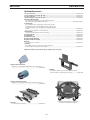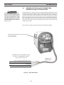
1
POWERCUT-1250 / 1500
MANUAL & MECHANIZED PLASMARC CUTTING PACKAGE
Installation, Operation and Service Manual (GB)
This manual provides complete instructions for MANUAL CONSOLES starting with Serial Number PxxJ245xxx, May 2003:
This manual provides complete instructions for MECHANIZED CONSOLES starting with Serial Number PxxJ316xxx, May 2003:
0558004232
Be sure this information reaches the operator.
You can get extra copies through your supplier.
caution
These INSTRUCTIONS are for experienced operators. If you are not fully familiar with the
principles of operation and safe practices for arc welding and cutting equipment, we urge
you to read our booklet, “Precautions and Safe Practices for Arc Welding, Cutting, and
Gouging,” Form 52-529. Do NOT permit untrained persons to install, operate, or maintain
this equipment. Do NOT attempt to install or operate this equipment until you have read
and fully understand these instructions. If you do not fully understand these instructions,
contact your supplier for further information. Be sure to read the Safety Precautions before installing or operating this equipment.
USER RESPONSIBILITY
This equipment will perform in conformity with the description thereof contained in this manual and accompanying labels and/or inserts when installed, operated, maintained and repaired in accordance with the instructions provided. This equipment must be checked periodically. Malfunctioning or poorly maintained equipment
should not be used. Parts that are broken, missing, worn, distorted or contaminated should be replaced immediately. Should such repair or replacement become necessary, the manufacturer recommends that a telephone
or written request for service advice be made to the Authorized Distributor from whom it was purchased.
This equipment or any of its parts should not be altered without the prior written approval of the manufacturer.
The user of this equipment shall have the sole responsibility for any malfunction which results from improper
use, faulty maintenance, damage, improper repair or alteration by anyone other than the manufacturer or a service facility designated by the manufacturer.
READ AND UNDERSTAND THE INSTRUCTION MANUAL BEFORE INSTALLING OR OPERATING.
PROTECT YOURSELF AND OTHERS!
186
TABLE OF CONTENTS
SECTION
PARAGRAPH
TITLE
PAGE
POWERCUT-1250/1500 MANUAL PLASMARC CUTTING PACKAGE
SECTION 1
1.0
1.1
1.2
DESCRIPTION...........................................................................................................................................193
General........................................................................................................................................................193
Scope...........................................................................................................................................................193
Manual Plasma.........................................................................................................................................194
SECTION 2
2.0
2.1
2.2
2.3
2.4
2.5
2.6
INSTALLATION........................................................................................................................................199
Installation - Manual Plasma Cutting Packages............................................................................199
General........................................................................................................................................................199
Equipment Required..............................................................................................................................199
Location......................................................................................................................................................199
Inspection...................................................................................................................................................199
Primary Electrical Input Connections - Manual Plasma Cutting Packages.........................200
Secondary Output Connections for Manual Plasma..................................................................202
SECTION 3
3.0
3.1
3.2
3.3
OPERATION..............................................................................................................................................203
Operation...................................................................................................................................................203
PowerCut-1250 / 1500 Controls.........................................................................................................203
PT-32EH Torches used with Manual Plasma Only........................................................................205
PT-32EH Possible Cutting Issues.........................................................................................................210
POWERCUT-1250/1500 MECHANIZED PLASMARC CUTTING PACKAGE
SECTION 1
1.0
1.1
1.2
DESCRIPTION...........................................................................................................................................213
General........................................................................................................................................................213
Scope...........................................................................................................................................................213
Mechanized Plasma................................................................................................................................214
SECTION 2
2.0
2.1
2.2
2.3
2.4
2.5
2.6
SECTION 3
3.0
3.1
3.2
3.3
INSTALLATION........................................................................................................................................219
Installation - Mechanized Plasma Cutting Packages..................................................................219
General........................................................................................................................................................219
Equipment Required..............................................................................................................................219
Location......................................................................................................................................................219
Inspection...................................................................................................................................................219
Primary Electrical Input Connections - Mechanized Plas Cutting Packages......................220
Secondary Output Connections for Mechanized Plasma.........................................................222
OPERATION..............................................................................................................................................225
Operation...................................................................................................................................................225
PowerCut-1250 / 1500 Controls.........................................................................................................225
PT-21AMX Torches used with Mechanized Plasma Only...........................................................226
PT-21AMX Possible Cutting Issues.....................................................................................................228
187
TABLE OF CONTENTS
SECTION
PARAGRAPH
TITLE
PAGE
SECTION 4
4.0
4.1
4.2
4.3
MAINTENANCE............................................................................................................363
General........................................................................................................................................................355
Inspection and Cleaning.......................................................................................................................355
Common Cutting Problems.................................................................................................................356
IGBT Handling & Replacement...........................................................................................................357
SECTION 5
5.0
5.1
5.2
5.3
TROUBLESHOOTING...................................................................................................367
Troubleshooting......................................................................................................................................359
Troubleshooting Guide.........................................................................................................................360
Reference Voltage Checks....................................................................................................................364
Sequence of Operation.........................................................................................................................365
SECTION 6REPLACEMENT PARTS.................................................................................................379
188
safety precautions
Safety Precautions
Users of ESAB welding and plasma cutting equipment have the ultimate responsibility for ensuring that
anyoneGB
who works on or near the equipment observes all the relevant safety precautions. Safety precautions
must meet the requirements that apply to this type of welding or plasma cutting equipment. The following
recommendations should be observed in addition to the standard regulations that apply to the workplace.
WARNING
All work must be carried out by trained personnel well acquainted with the operation of the welding or plasma
cutting equipment. Incorrect operation of the equipment may lead to hazardous situations which can result in
Arc
welding
andand
cutting
can betoinjurious
to yourself and others. Take precausions when welding.
injury to
the
operator
damage
the equipment.
Ask for your employer’s safety practices which should be based on manufacturers’ hazard data.
1.
Anyone
who uses
welding
ELECTRIC
SHOCK
- Can or
killplasma cutting equipment must be familiar with:
Install and earth the welding unit in accordance with applicable standards.
- itsS operation
S
Do not touch live electrical parts or electrodes with bare skin, wet gloves or wet clothing.
- location
of emergency stops
S
Insulate yourself from earth and the workpiece.
- itsS function
Ensure your working stance is safe.
- relevant
precautions
FUMESsafety
AND GASES
- Can be dangerous to health
S
Keep
out of
the fumes.
- welding
andyour
/ orhead
plasma
cutting
Use ventilation, extraction at the arc, or both, to take fumes and gases away from your breathing zone
and the general area.
The operator must ensure that:
ARC RAYS - Can injure eyes and burn skin.
- noS unauthorized
stationed
within
the working
area ofand
thefilter
equipment
it is started up.
Protect yourperson
eyes and
body. Use
the correct
welding screen
lens andwhen
wear protective
- no oneclothing.
is unprotected when the arc is struck.
S
Protect bystanders with suitable screens or curtains.
HAZARD
TheFIRE
workplace
must:
S
Sparks (spatter) can cause fire. Make sure therefore that there are no inflammable materials nearby.
- be suitable for the purpose
- Excessive noise can damage hearing
- beNOISE
freeProtect
from
drafts
S
your ears. Use earmuffs or other hearing protection.
S
Warn bystanders of the risk.
Personal
safety equipment:
MALFUNCTION
- Call for expert assistance in the event of malfunction.
S
2.
3.
4.
- Always wear recommended
personal safety equipment, such as safety glasses, flame proof
Read and understand the instruction manual before installing or operating.
clothing, safety gloves.
PROTECT
YOURSELF
AND rings,
OTHERS!
- Do not wear loose fitting items, such
as scarves,
bracelets,
etc., which could become
trapped or cause burns.
5.
General precautions:
- Make sure the return cable is connected securely.
- Work on high
voltage equipment may only be carried out by a qualified electrician.
WARNING!
- Appropriate fire extinquishing equipment must be clearly marked and close at hand.
Read and understand the instruction manual before installing
- Lubrication
and maintenance must not be carried out on the equipment during operation.
or operating.
CAUTION!
CAUTION
Class A (400V CE) equipment is not intended for use in resi-
Class
A equipment
not intended
for use in
residential
locations
dential
locationsiswhere
the electrical
power
is provided
bywhere
the
the
electrical
power
is
provided
by
the
public
low-voltage
supply
public low-voltage supply system. There may be potential difsystem. There may be potential difficulties in ensuring electromagnic
ficulties inofensuring
electromagnetic
compatibility
Class A
compatibility
class A equipment
in those locations,
due toofconducted
in those
locations due to conducted as well as radiasequipment
well as radiated
disturbances.
ated disturbances.
189
Do not dispose of electrical equipment together with normal waste!
safety precautions
WARNING
WELDING AND PLASMA CUTTING CAN BE INJURIOUS TO YOURSELF AND
OTHERS. TAKE PRECAUTIONS WHEN WELDING OR CUTTING. ASK FOR
YOUR EMPLOYER’S SAFETY PRACTICES WHICH SHOULD BE BASED ON
MANUFACTURERS’ HAZARD DATA.
ELECTRIC SHOCK - Can kill.
- Install and earth (ground) the welding or plasma cutting unit in accordance with applicable standards.
- Do not touch live electrical parts or electrodes with bare skin, wet gloves or wet clothing.
- Insulate yourself from earth and the workpiece.
- Ensure your working stance is safe.
FUMES AND GASES - Can be dangerous to health.
- Keep your head out of the fumes.
- Use ventilation, extraction at the arc, or both, to take fumes and gases away from your breathing zone
and the general area.
ARC RAYS - Can injure eyes and burn skin.
- Protect your eyes and body. Use the correct welding / plasma cutting screen and filter lens and wear
protective clothing.
- Protect bystanders with suitable screens or curtains.
FIRE HAZARD
- Sparks (spatter) can cause fire. Make sure therefore that there are no inflammable materials nearby.
NOISE - Excessive noise can damage hearing.
- Protect your ears. Use earmuffs or other hearing protection.
- Warn bystanders of the risk.
MALFUNCTION - Call for expert assistance in the event of malfunction.
READ AND UNDERSTAND THE INSTRUCTION MANUAL BEFORE INSTALLING OR OPERATING.
PROTECT YOURSELF AND OTHERS!
190
POWERCUT-1250 / 1500
MANUAL PLASMARC CUTTING PACKAGE
191
192
section 1description
1.0 General
Use only the ESAB PT-32EH Plasmarc
torch with this console. Use of torches not
designed for use with this console could
create an ELECTRIC SHOCK HAZARD.
The Powercut-1250 / 1500 is a compact, completely self-contained plasma cutting
system. As shipped, the system is fully assembled and ready to cut after being
connected to input power and a source of compressed air (90-150 psi / 6.2 to
10.3 bar). The Powercut package uses the heavy-duty PT-32EH (Manual Plasma)
torch to deliver cutting power for severing materials up to 1-1/2 inch (38.1mm)
thick on the PC-1250 and 1-3/4 inch (45mm) thick on the PC-1500. Refer to the
following pages for descriptions of the Powercut packages available as well as
performance specifications.
1.1 scope
The purpose of this manual is to provide the operator with all the information
required to install and operate the Powercut plasma arc cutting package. Technical reference material is also provided to assist in troubleshooting the cutting
package.
Typical Front View
"Single Voltage" Version Back View
193
section 1description
1.2
MANUAL PLASMA
1.2.1
PC-1250 MANUAL PLASMA
The PowerCut-1250 plasma cutting package combines the
proven reliability of the PowerCut-1250 with the newly
designed PT-32EH torch. The very strong composite case
material makes the PowerCut-1250 an excellent addition
to any equipment rental fleet. The PT-32EH plasma cutting
torch is designed to provide increased performance and
longer consumable life resulting in higher production rates
at lower costs.
Specifications: PowerCut-1250
Cuts 1-1/4 in. (32mm); severs 1-1/2 in. (38mm)
1 ph. Input..................................................208/230 vac, 1 ph, 50/60 Hz, 67/61 A
1 ph. Output..................................................................70 amps @ 60% duty cycle
3 ph. Input..................................................208/230 vac, 3 ph, 50/60 Hz, 33/29 A
..................................................................230/460 vac, 3 ph, 50/60 Hz, 29/20 A
..................................................................................400 vac, 3 ph, 50/60 Hz, 18 A
...................................................................................575 vac, 3ph, 50/60 Hz, 15 A
3 ph. Output............................................................... 70 amps @ 100% duty cycle
Dimensions . ................................................................................W = 12.5” (318mm)
......................................................................................................H = 16.5” (419mm)
..................................................................................................... D = 31.5” (800mm)
Weight...................................................................................................... 86 lbs. (39kg)
Air Requirements . ............................350 cfh @ 80 psig (165 l/min @ 5.5 bars)
PT-32EH Cut Data-70 AMPS
Powercut-1250, PT-32EH, 70A Nozzle P/N 0558002618
Air Pressure - 80 psi (5.5 bar), 5/32” (4.0 mm)Standoff
Torch
PowerCut-1250 uses the PT-32EH torch. For complete list and
breakdown of parts, refer to Figure 1.1.
Ordering Information:
Max Speeds
Carbon Steel
Plate
Inches (mm)
PowerCut-1250, 208/230/460 V, 25’ (7.6m) PT-32EH................ 0558001933
PowerCut-1250, 208/230/460 V, 50’ (15.2m) PT-32EH............. 0558001934
PowerCut-1250, 575 V, 25’ (7.6m) PT-32EH................................. 0558001939
PowerCut-1250, 575 V, 50’ (15.2m) PT- 32EH.............................. 0558001940
PowerCut-1250, 400 V, “CE” 25’ (7.6m) PT-32EH......................... 0558001936
PowerCut-1250, 400 V, “CE” 50’ (15.2m) PT-32EH....................... 0558001937
PowerCut-1250, 460 V, 25’ (7.6m) PT-32EH................................. 0558005332
PowerCut-1250, 460 V, 50’ (15.2m) PT- 32EH.............................. 0558005333
0.250 (6.35)
0.500 (12.7)
0.750 (19.05)
1.000 (25.4)
1.250 (31.75)
1.500 (38.1)
The components that are included in the Powercut-1250 packages (Console,
Torch, Spare Parts Kit) may be purchased separately by using the appropriate
P/N when placing orders. Individual part numbers are listed below:
Consoles:
PowerCut-1250 (208)230/460 V, 50/60 Hz, 1/3-ph................... 0558001935
PowerCut-1250 (208)230/460 V, 50/60 Hz, 1/3-ph (BL)........0558001935F
PowerCut-1250 575 V, 50/60 Hz, 3-ph........................................... 0558001941
PowerCut-1250 400 V, CE, 50 Hz, 3-ph.......................................... 0558001938
PowerCut-1250 460 V, 60 Hz, 3-ph................................................. 0558005331
PT-32EH Torches:
PT-32EH Torch, 25-ft. (7.6m) ............................................................ 0558003548
PT-32EH Torch, 50-ft. (15.2m).......................................................... 0558003549
Spare Parts Kits: (see section 1.2.3)
PT-32EH Spare Parts Kit . ................................................................... 0558003508
PT-32EH, 400 V Long Heat Shield (LHS), Spare Parts Kit, CE units . .............
only............................................................................................................ 0558003560
194
Drop Cut
IPM (mm/min)
131
50 21
10
6
---
(3327.4)
(1270)
(533.4)
(254)
(152.4)
(---)
Sever
IPM (mm/min)
135
53 23
12 7
3 (3429)
(1346.2)
(584.2)
(304.8)
(177.8)
(76.2)
section 1description
1.2.2
PC-1500 MANUAL PLASMA
The PowerCut-1500 plasma cutting package combines the
proven reliability of the PowerCut-1500 with the newly
designed PT-32EH torch. The very strong composite case
material makes the PowerCut-1500 an excellent addition
to any equipment rental fleet. The PT-32EH plasma cutting
torch is designed to provide increased performance and
longer consumable life resulting in higher production rates
at lower costs.
Specifications: PowerCut-1500
Cuts 1-1/2 in. (38mm); severs 1-3/4 in. (45mm)
1 ph. Input..................................................208/230 vac, 1 ph, 50/60 Hz, 82/74 A
1 ph. Output..................................................................90 amps @ 40% duty cycle
3 ph. Input..................................................208/230 vac, 3 ph, 50/60 Hz, 44/40 A
..................................................................230/460 vac, 3 ph, 50/60 Hz, 40/27 A
...................................................................................400 vac, 3ph, 50/60 Hz, 26 A
400V CE Mains Supply . ............................................................... Ssc min 3.8MVA
................................................................................................................. Zmax 0.042Ω
...................................................................................575 vac, 3ph, 50/60 Hz, 18 A
3 ph. Output..................................................................90 amps @ 60% duty cycle
Dimensions . ................................................................................W = 12.5” (318mm)
......................................................................................................H = 16.5” (419mm)
..................................................................................................... D = 31.5” (800mm)
Weight...................................................................................................94 lbs. (42.7kg)
Air Requirements . ............................350 cfh @ 80 psig (165 l/min @ 5.5 bars)
PT-32EH Cut Data-90 AMPS
Powercut-1500, PT-32EH, 90A Nozzle P/N 0558002837
Air Pressure - 80 psi (5.5 bar) , 5/32” (4.0 mm)Standoff
400V CE Mains Supply, Ssc min
Minimum short circuit power on the network in accordance with
IEC61000-3-12.
Max Speeds
Carbon Steel
400V CE Mains Supply, Zmax
Maximum permissible line on the network impedance in accordance
with IEC61000-3-11.
Plate
Inches (mm)
0.250 (6.35)
0.500 (12.7)
0.750 (19.05)
1.000 (25.4)
1.250 (31.75)
1.500 (38.1)
Torch
PowerCut-1500 uses the PT-32EH torch. For complete list and
breakdown of parts, refer to Figure 1.1.
Ordering Information:
PowerCut-1500, 230/460 V, 25’ (7.6m) PT-32EH......................... 0558001942
PowerCut-1500, 230/460 V, 50’ (15.2m) PT-32EH...................... 0558001943
PowerCut-1500, 575 V, 25’ (7.6m) PT-32EH................................. 0558001948
PowerCut-1500, 575 V, 50’ (15.2m) PT- 32EH.............................. 0558001949
PowerCut-1500, 400 V, “CE” 25’ (7.6m) PT-32EH......................... 0558001945
PowerCut-1500, 400 V, “CE” 50’ (15.2m) PT-32EH....................... 0558001946
PowerCut-1500, 460 V, 25’ (7.6m) PT-32EH................................. 0558005902
PowerCut-1500, 460 V, 50’ (15.2m) PT- 32EH.............................. 0558005903
PowerCut-1500, 400 V, 25’ (7.6m) PT-32EH.................................. 0558007827
Drop Cut
IPM (mm/min)
151 (3835.4)
56 (1422.4)
25 (635)
16 (406.4)
11 (279.4)
7 (177.8)
Sever
IPM (mm/min)
153 (3886.2)
58 (1473.2)
26 (660.4)
18 (457.2)
12 (304.8)
8 (203.2)
PT-32EH Torches:
PT-32EH Torch, 25-ft. (7.6m)............................................................. 0558003548
PT-32EH Torch, 50-ft. (15.2m).......................................................... 0558003549
Spare Parts Kits: (see section 1.2.3)
PT-32EH Spare Parts Kit . ................................................................... 0558003062
PT-32EH, 400 V Long Heat Shield (LHS), Spare Parts Kit, CE units . .............
only............................................................................................................ 0558003557
The components that are included in the Powercut-1500 packages (Console,
Torch, Spare Parts Kit) may be purchased separately by using the appropriate
P/N when placing orders. Individual part numbers are listed below:
Consoles:
PowerCut-1500 (208)230/460 V, 50/60 Hz, 1/3-ph................... 0558003570
PowerCut-1500 (208)230/460 V, 50/60 Hz, 1/3-ph (BL).......... 0558003517
PowerCut-1500 575 V, 50/60 Hz, 3-ph........................................... 0558001950
PowerCut-1500 400 V, CE, 50 Hz, 3-ph......................................... 0558001947
PowerCut-1500 460 V, 50/60 Hz, 3-ph........................................... 0558005900
PowerCut-1500 400 V, 50 Hz, 3-ph................................................. 0558007826
195
section 1description
1.2.3
SPARE PARTS / OPTIONAL ACCESSORIES (PC-1250 / 1500 MANUAL PLASMA)
Spare Parts Kits:
Contents of PT-32EH Spare Parts Kit, 70 amp
P/N 0558003508
Contents of PT-32EH (LHS) Spare Parts Kit, 70 amp
P/N 0558003560, "CE"units only
Description
P/N
Quantity
Description
P/N
Quantity
Heat Shield
70 amp Nozzle
40 amp drag Nozzle
Electrode
Valve Pin
Fuse 2amp, 600vdc
Stand-off Guide
Wrench
Lubricant
Long Heat Shield (LHS)
70 amp Nozzle
40 amp drag Nozzle
Electrode
Valve Pin
Fuse 2amp, 600vdc
Drag Heat Shield Wrench
Lubricant
0558001957
0558002618
0558002908
0558001969
0558001959
0558001379
0558002393
19129 (0558000808)
17672 (0558000443)
2
4
1
3
1
1
1
1
1
0558003110
0558002618
0558002908
0558001969
0558001959
0558001379
0558004206
19129 (0558000808)
17672 (0558000443)
2
4
1
3
1
1
1
1
1
The PowerCut-1250 comes out of the box ready to go. The torch is attached with parts in place, primary cord is attached and the filter/regulator is
installed. Just hook up the air, power and begin cutting.
(NOTE: Part numbers in parenthesis apply to "CE"/European units only.)
Contents of PT-32EH Spare Parts Kit, 90 amp
P/N 0558003062
Contents of PT-32EH (LHS) Spare Parts Kit, 90 amp
P/N 0558003557, "CE" units only
Description
P/N
Quantity
Description
P/N
Quantity
Heat Shield
90 amp Nozzle
40 amp drag Nozzle
Electrode
Valve Pin
Fuse 2amp, 600vdc
Stand-off Guide
Wrench
Lubricant
Long Heat Shield (LHS)
90 amp Nozzle
40 amp drag Nozzle
Electrode
Valve Pin
Fuse 2amp, 600vdc
Drag Heat Shield Wrench
Lubricant
0558001957
0558002837
0558002908
0558001969
0558001959
0558001379
0558002393
19129 (0558000808)
17672 (0558000443)
2
4
1
3
1
1
1
1
1
0558003110
0558002837
0558002908
0558001969
0558001959
0558001379
0558004206
19129 (0558000808)
17672 (0558000443)
2
4
1
3
1
1
1
1
1
The PowerCut-1500 comes out of the box ready to go. The torch is attached with parts in place, primary cord is attached and the filter/regulator is
installed. Just hook up the air, power and begin cutting.
85W51 (0558003694)
(Supplied with head)
Valve Pin
0558001959
Electrode
0558001969
Heat Shield
0558001957
Long Heat Shield
0558003110
PT-32EH Torch Head - 0558003412
Nozzle
40 AMP - 0558002908 (Drag Cutting)
50/70 AMP - 0558002618
90 AMP - 0558002837
Figure 1-1. PT-32EH Torch
196
section 1description
Optional Accessories:
70 A Spare Parts Kit.........................................................................................................................................0558003508
70 A 400 V LHS Spare Parts Kit, "CE" units......................................................................................................0558003560
90 A Spare Parts Kit..........................................................................................................................................0558003062
90 A 400 V LHS Spare Parts Kit, "CE" units......................................................................................................0558003557
Plasma Flow Measuring Kit:
This valuable troubleshooting tool allows measurement of
the actual plasma gas flow through the torch....................................................................................................... 19765 (0558000739)
Torch Guide Kit:
This complete kit, in a rugged plastic carrying case, includes
attachments for circle and straight line cutting on ferrous and
non-ferrous metals, 1 3/4" - 42" (44.5mm - 1066.8 mm) Radius,
Deluxe....................................................................................................................................................................................................0558003258
Basic, 1 3/4” - 28” (44.5mm - 711.2 mm) Radius .....................................................................................................................0558002675
Stand-off Guide
For proper stand-off distance when drag cutting.................................................................................................................0558002393
40 amp Drag Nozzle ..........................................................................................................................................................................0558002908
Gouging Nozzle ...................................................................................................................................................................................0558003089
Heat Shield Gouging .........................................................................................................................................................................0558003090
Drag Heat Shield (Standard) .........................................................................................................................................................0558003374
Drag Heat Shield (Heavy Duty) ....................................................................................................................................................0558004206
Wheel Kit
For easy transport of system..........................................................................................................................................................0558003060
Torch Wrap
This enables operator to store spare parts kit, wrap torch
and work cable for easy transport and storage.........................................................................................................................0558003059
(NOTE: Part numbers in parenthesis apply to "CE"/European units only.)
Drag Heat Shield (Standard)
Maintains a constant stand-off, Good life in most applications.............
............................................................................................................... 0558003374
Torch Wrap
This enables operator to store spare parts kit, wrap torch
and work cable for easy transport and storage................... 0558003059
Drag Heat Shield (Heavy Duty)
Maintains a constant stand-off, Long life, Suitable for piercing.............
............................................................................................................... 0558004206
Powercut shown with Optional Torch Wrap
and Spare Parts Kit Holder installed.
Wheel Kit
For easy transport of system....................................................... 0558003060
197
section 1description
198
section 2installation
2.0
INSTALLATION - MANUAL PLASMA CUTTING PACKAGE
2.1
General
Proper installation is important for satisfactory and trouble-free operation of
the PowerCut cutting package. It is suggested that each step in this section be
studied carefully and followed closely.
2.2
Installing or placing any type of filtering
device will restrict the volume of intake
air, thereby subjecting the power source
internal components to overheating.
The warranty is void if any type of filter
device is used.
Equipment Required
A source of clean, dry air that supplies 350 cfh (165.2 l/m) at 80 psig (5.5 bar) is
required for the cutting operation. The air supply should not exceed 150 psig
(10.3 bar) (the maximum inlet pressure rating of the air filter-regulator supplied
with the package).
2.3
Location
Adequate ventilation is necessary to provide proper cooling of the PowerCut.
The amount of dirt, dust, and excessive heat to which the equipment is exposed,
should be minimized. There should be at least one foot of clearance between
the PowerCut power source and wall or any other obstruction to allow freedom
of air movement through the power source.
2.4
Inspection
A.
Remove the shipping container and all packing material and inspect for
evidence of concealed damage which may not have been apparent upon
receipt of the PowerCut. Notify the carrier of any defects or damage at
once.
B.
Check container for any loose parts prior to disposing of shipping materials.
C.
Check air louvers and any other openings to ensure that any obstruction
is removed.
199
section 2installation
2.5
ELECTRIC SHOCK CAN KILL! Precautionary measures should be taken to provide
maximum protection against electrical
shock. Be sure that all power is off by
opening the line (wall) disconnect switch
and by unplugging the power cord to the
unit when connections are made inside of
the power source.
Primary Electrical Input Connections - MANUAL PLASMA CUTTING PACKAGE
The PowerCut-1250 / 1500 consoles are equipped with approximately 10-ft. of
4-conductor input power cable for 3-phase connection. If single-phase connection
is desired, tape back the red (lt. blue) wire on the input power cable. Connect the
single-phase input to the white and black wires only. When operating this machine
from a single-phase source, it must be connected to a dedicated 100 Amp feed.
Due to the higher input current requirements, the duty cycle of the machine is
lower than in three-phase operation. Single phase duty cycle is 60% for PC-1250
and 40% for PC-1500.
Connect your air supply to the inlet connection of the filter-regulator.
Prefiltered DRY AIR SUPPLY (Customer Supplied)
(90 to 150 psig max)
(6.2 to 10.3 bars max)
CUSTOMER FUSED LINE DISCONNECT SWITCH
(See Table 2.3 and WARNING in regards to
chassis ground in Section 2.5.)
Red (Lt Blue) NOT USED ON SINGLE PHASE
White (Brown)
Black (Black)
Green (Yellow/Green)
Figure 2-1. Input Connections
200
PRIMARY INPUT
POWER CABLE
section 2installation
ELECTRIC SHOCK CAN KILL! Before making
electrical input connections to the power
source, "Machinery Lockout Procedures"
should be employed. If the connections
are to be made from a line disconnect
switch, place the switch in the off position
and padlock it to prevent inadvertent
tripping . If the connection is made from
a fusebox, remove the corresponding
fuses and padlock the box cover. If it is
not possible to use padlocks, attach a
red tag to the line disconnect switch (or
fuse box) warning others that the circuit
is being worked on.
Before connecting to input power, make sure there is a line (wall) disconnect
switch with fuses or circuit breakers at the main power panel. You may either use
the factory-installed input power cable (4/c, type SO (90 °C), 10 ft (3.1 m) length)
or provide your own input power leads. If you choose to provide your own, make
sure they are insulated copper conductors. You must have two (single-phase) or
three (three-phase) power leads and one ground wire. The wires may be heavy
rubber covered cable or may be run in a solid or flexible conduit. Refer to Table
2-1 and 2-2 for recommended input conductors and line fuse sizes.
Table 2-1. ( PC-1250 ) Recommended Sizes
For Input Conductors and Line Fuses
Input Requirements
Volts
Phase
Amps
The chassis must be connected to an approved electrical ground. Failure to do
so may result in electrical shock, severe
burns or death.
208
208
230
230
460
400
575
Before making any connections to the
power source output terminals, make
sure that all primary input power to the
power source is deenergized (off) at the
main disconnect switch and that the input
power cable is unplugged.
1
3
1
3
3
3
3
67A
33A/Ph.
61A
29A/Ph.
20
18
15
Conductor
Size
CU/AWG
Amps
6
6
6
6
6
6mm2
10
100
50
100
50
50
50
25
Table 2-2. ( PC-1500 ) Recommended Sizes
For Input Conductors and Line Fuses
Input Requirements Volts
Phase
Amps
Input & GndFuse
208
208
230
230
460
400
575
NOTE !!!
1
3
1
3
3
3
3
82A
44A/Ph.
74A
40A/Ph.
27
24
18
Input & GndFuse
Conductor
Size
CU/AWG
Amps
6
6
6
6
6
6mm2
10
100
80
100
80
50
50
50
400V CE Mains Supply Requirements:
High power equipment may, due to the primary current drawn from the mains supply, influence the power quality of the grid. Therefore connection restrictions or requirements regarding the maximum permissible mains impedance or the required minimum supply capacity at the interface point to the public grid
may apply for some types of equipment (see technical data). In this case it is the responsibility of the
installer or user of the equipment to ensure, by consultation with the distribution network operator if
necessary, that the equipment may be connected.
201
section 2installation
2.6 SECONDARY OUTPUT CONNECTIONS FOR Manual Cutting
The torch comes factory installed.
Clamp the work cable to the workpiece. Be sure
the workpiece is connected to an approved earth
ground with a properly sized ground cable.
WORK
SAFETY GROUND
PT-32EH
Figure 2-2. PowerCut Interconnection Diagram
202
section 3operation
A
B
C
D
Figure 3-1A. PowerCut-1250 / 1500 Controls
3.0
Operation
3.1
PowerCut-1250 / 1500 CONTROLS
A.
Power Switch. When placed in ON position, the white power light will glow indicating control circuit is energized.
B.
Air Test Switch. When placed in TEST position, air filter-regulator can be adjusted
to desired pressure (80 psig / 5.5 bar) before cutting operations. Allow air to flow for
a few minutes. This should remove any condensation that may have accumulated
during shutdown period. Be sure to place switch in OPERATE position before starting
cutting operations.
C.
Trigger Lock Switch.
1. Manual Operation using the PT-32EH torch - When placed in LOCK position,
this permits releasing torch switch button after cutting arc has been initiated. To
extinguish arc at end of cut, press and release torch switch button again or pull
torch away from work. When placed in UNLOCK position, torch switch must be
held closed by the operator during the entire cutting operation and then released
at the end of cut.
2. Mechanized Operation using the PT-21AMX torch - In mechanized operation the
Trigger Lock function disabled. Instead, the switch functions as an "Auto-Restrike"
selector. To turn Auto-Restrike "on" (grate cutting), place the switch in the up
position. To turn Auto-Restrike "off" (grate cutting), place the switch in the down
position.
203
TRIGGER
LOCK
Auto-Restrike "on"
UNLOCK
Auto-Restrike "off"
section 3operation
E
F
G
H
I
Figure 3-1B. PowerCut-1250 / 1500 Controls
D. Output Current Control. Adjustable from 20 to 70 amperes on Powercut-1250. Adjustable
from 20 to 90 amperes on Powercut-1500.
E. Power "ON" Indicator: Illuminates whenever the front panel power switch is in the ON
position.
F. AC Line Indicator or High/Low Line Voltage Indicator: This fault light will blink when
the input voltage is outside the “+ or -” 15% range of the input rating.
G. Gas Flow Indicator: This fault light will blink when the air flow supply is low or has no back
pressure.
H.Fault Indicator: When this light blinks, either the system failed to initiate a pilot arc after
a number of attempts, or there has been an over-current event within the system. If the
light blinks for 10 seconds and then stops, the problem is pilot arc initiation. Check the
consumables in the torch.
If the light continues to blink, and the system does not reset, the fault is an over-current
event. See troubleshooting section.
I.
Over Temperature Indicator: This fault light will blink to indicate that the duty cycle has
been exceeded. Allow the power source to cool down before returning to operation.
All fault signals will remain on for a minimum of 10 seconds. If fault clears, all will
reset automatically except for over-current. To clear over-current, the power must be
shut off for 5 seconds and then turned back on.
204
section 3operation
3.2
ELECTRIC SHOCK can kill.
• Do NOT operate the unit with the cover
removed.
• Do NOT apply power to the unit while
holding or carrying the unit.
• Do NOT touch any torch parts forward of the torch handle (nozzle, heat shield,
electrode, etc.) with power switch
on.
3.2.1 Cutting with the POWERCUT-1250 / 1500 using the
pt-32eh torch (manual plasma only)
Use the following procedures to cut with the PT-32EH torch.
A.
Make sure that the wall disconnect switch is on. Turn on the Front Panel Power
Switch.
B.
Set Pressure Regulator to 80 psig (5.5 bar).
C.
Hold the torch nozzle approximately 1/8 to 3/16 inch (3.2 to 4.8 mm) above
the work and tilted at about 15 - 30°. This reduces the chance of spatter entering the nozzle. If the PT-32EH's stand-off guide (P/N 0558002393) is being
used, the distance between Electrode and Work Piece will be approx. 3/16"
(4.8 mm).
D.
Depress the torch switch. Air should flow from the torch nozzle.
E.
Two seconds after depressing the torch switch, the pilot arc should start. The
main arc should immediately follow, allowing the cut to begin. (If using the
trigger LOCK mode, torch switch may be released after establishing the cutting arc.) See note.
ARC RAYS can burn eyes and skin;
NOISE can damage hearing.
• Wear welding helmet with No. 6 or 7 lens
shade.
• Wear eye, ear, and body protection.
NOTE: Trigger Lock Switch.
Manual Operation using the PT-32EH
torch - When placed in LOCK position,
this permits releasing torch switch button after cutting arc has been initiated.
To extinguish arc at end of cut, press and
release torch switch button again or pull
torch away from work. When placed in
UNLOCK position, torch switch must be
held closed by the operator during the
entire cutting operation and then released
at the end of cut.
PT-32EH TORCH USED WITH MANUAL PLASMA ONLY
Position the PowerCut at least 10 feet (3
meters) from the cutting area. Sparks and
hot slag from the cutting operation can
damage the unit.
Trigger Lock Switch
205
section 3operation
F.
After starting the cut, the torch should be maintained at a 5-15° forward angle. This
angle is especially useful in helping to create a "drop" cut. When not using the stand-off
guide, the nozzle should be held approximately 1/4 inch (6.4mm) from the work.
CUT
DIRECTION
Figure 3-2a. Recommended Torch Angle of 5o to 15o During Cutting
IMPORTANT!!!
Maintain Proper
Stand-Off Distance
3/16 to 1/4 Inch
(4.8 to 6.4mm)
Power Output increases with Stand Off Distance!
Figure 3-2b. Stand-off vs. Power Output During Cutting
G.
H.
When ending a cut, the torch switch should be released (press and release if using
trigger LOCK mode) and the torch lifted off the workpiece just before the end of the
cut. This is to prevent the high frequency from reigniting after cutting arc extinguishes
and causing damage to the nozzle (double arcing).
For rapid re-starts, such as grate or heavy mesh cutting, do not release the torch
switch. In the postflow mode, the arc can be re-started immediately by depressing
the torch switch. This avoids the 2-second preflow portion of the cutting cycle.
206
section 3operation
3.2.2
Drag Cutting with the PT-32EH Torch / PowerCut package.
A. LOW CURRENT AUTO-DRAG FEATURE
If drag cutting is desired for thin material under 3/8" (9.5mm) thick, remove
the standard 70 / 90 amp nozzle from the PT-32EH torch and install ESAB's
40 amp nozzle. Lower the current level setting to be within the AUTODRAG range of 20 to 40 amps (see Auto Drag Scale on front panel). Then
follow steps in Section 3.2.1. Also refer to PT-32EH Instruction Manual No.
F-15-747.
Drag cutting, even with lower current
levels may significantly reduce the life of
torch consumables. Attempting to Drag
Cut with higher currents greater than (40
amps) may cause immediate catastrophic
consumable damage.
B. HIGH CURRENT DRAG CUTTING
If drag cutting is desired on materials above 3/8” (9.5mm) thick, be sure that
the 70 amp / 90 amp nozzle is installed in the PT-32EH torch. Attach ESAB's
stand-off guide and operate as shown in Figure 3.3.
2
1
WHEN THE ARC BREAKS
THROUGH THE WORK, BRING
THE TORCH TO AN UPRIGHT POSITION AND PROCEED TO CUT.
TO START A PIERCE, TILT THE TORCH TO
PREVENT MOLTEN MATERIAL FROM COMING BACK AGAINST AND DAMAGING
THE TORCH.
Figure 3-3. Piercing Technique using the PT-32EH
207
section 3operation
3.2.3
PT-32EH TORCH PARTS INSTALLATION (MANUAL PLASMA ONLY)
PLACE THE VALVE PIN INTO THE ELECTRODE
AND SCREW THE ELECTRODE INTO THE
TORCH HEAD AND TIGHTEN SECURELY WITH
WRENCH #19129.
Make sure power switch on POWERCUT
is in OFF position before working on the
torch.
1
The PT-32EH torch head contains a gas
flow check valve that acts in conjunction
with the flow switch and circuitry within
the power source. This system prevents
the torch from being energized with high
voltage if the torch switch is accidentally
closed when the shield is removed. Always
replace torch with the with the proper
torch manufactured by ESAB since it
alone contains ESAB's patented safety
interlock.
*VALVE
PIN
ELECTRODE
NOZZLE
SHIELD
2
PLACE NOZZLE INTO HEAT
SHIELD AND THREAD
THIS ASSEMBLY TO THE
TORCH BODY AND HAND
TIGHTEN.
3
IMPORTANT!
MAKE SHIELD VERY TIGHT!
valve pin is a crucial member of the system. Its function
*The
is to open the gas flow check valve that is permanently
assembled within the torch head. If the pin is not correctly
placed in the electrode, the valve will not open and the
system will not function. The valve pin also improves electrode cooling by increasing the velocity of air over the inner
surface of the electrode.
Fig 3.4. Exploded View of PT-32EH Torch
208
section 3operation
ADJUST GUIDE BY TURNING
IN A CLOCKWISE DIRECTION
ONLY. THIS WILL PREVENT
ACCIDENTAL LOOSENING
OF SHIELD.
IF GUIDE IS TOO TIGHT ON SHIELD, OPEN
SLOT WITH SCREWDRIVER.
STEEL GUARD
STAND OFF GUIDE
P/N 0558002393
THIN GAUGE MATERIALS
CAN BE CUT WITH 1/16" (1.6 mm)
TORCH-TO-WORK DISTANCE
ADJUST TO 3/16" (4.8 mm) FOR
MATERIALS OVER 1/4" (6.4 mm) THICK
1/16" (1.6 mm) TO
1/4" (6.4mm)
TORCH-TO-WORK
GUIDE AGAINST
STRAIGHT EDGE
OR FREE-HAND
CUT
IF TOO LOOSE, CLOSE
SLOT WITH VISE OR
LARGE PLIERS.
Figure 3-5. Installation and Operation of Stand-off Guide (PT-32EH ONLY)
209
section 3operation
3.3
PT-32EH POSSIBLE Cutting ISSUES
Replace when eroded beyond
.06"(1.5mm) Depth.
REPLACE ELECTRODE BEFORE PITTING
BECOMES DEEPER THAN .06 INCH (1.5
MM)
Figure 3-6. Electrode Wear Limit
NOTE: When replacing the nozzle, always inspect the electrode for wear. If more
than .06" (1.5mm) of electrode has eroded, replace the electrode. If the
electrode is used beyond this recommended wear limit, damage to the torch
and power source may occur. Nozzle life is also greatly reduced when using
the electrode below the recommended limit.
210
POWERCUT-1250 / 1500
MECHANIZED PLASMARC CUTTING PACKAGE
211
212
section 1description
1.0 General
Use only the ESAB PT-21AMX Plasmarc
torch with this console. Use of torches not
designed for use with this console could
create an ELECTRIC SHOCK HAZARD.
The Powercut-1250 / 1500 is a compact, completely self-contained plasma cutting system. The system is shipped with the PT-21AMX mechanized torch. Torch
must be wired to the console before operation. See section 2.6.1. The system is
ready to cut after connections are made to the torch, input power and a source
of compressed air (90-150 psi / 6.2 to 10.3 bar). The mechanized Powercut package uses the PT-21AMX mechanized plasma torch to deliver cutting power for
severing materials up to 1-1/2 inch (38.1mm) thick on the PC-1250 and 1-3/4
inch (45mm) thick on PC-1500. Refer to the following pages for descriptions of
the Powercut packages available as well as performance specifications.
1.1 scope
The purpose of this manual is to provide the operator with all the information
required to install and operate the Powercut plasma arc cutting package. Technical reference material is also provided to assist in troubleshooting the cutting
package.
Typical Front View
"Single Voltage" Version Back View
213
section 1description
1.2
MECHANIZED PLASMA
1.2.1
PC-1250 MECHANIZED PLASMA
The PowerCut-1250 plasma cutting package combines the
proven reliability of the PowerCut-1250 with the newly
designed PT-21AMX torch. The PT-21AMX plasma cutting
torch is designed to provide increased performance and
longer consumable life resulting in higher production rates
at lower costs.
Specifications: PowerCut-1250
Cuts 1-1/4 in. (32mm)
1 ph. Input..................................................208/230 vac, 1 ph, 50/60 Hz, 67/61 A
1 ph. Output..................................................................70 amps @ 60% duty cycle
3 ph. Input..................................................208/230 vac, 3 ph, 50/60 Hz, 33/29 A
..................................................................230/460 vac, 3 ph, 50/60 Hz, 29/20 A
..................................................................................400 vac, 3 ph, 50/60 Hz, 18 A
...................................................................................575 vac, 3ph, 50/60 Hz, 15 A
3 ph. Output............................................................... 70 amps @ 100% duty cycle
Dimensions . ................................................................................W = 12.5” (318mm)
......................................................................................................H = 16.5” (419mm)
..................................................................................................... D = 31.5” (800mm)
Weight...................................................................................................... 86 lbs. (39kg)
Air Requirements . ............................350 cfh @ 80 psig (165 l/min @ 5.5 bars)
Torch
PowerCut-1250 uses the PT-21AMX torch. For complete list and
breakdown of parts, refer to Figure 1.2.
PT-21AMX Cut Data-70 AMPS
Powercut-1250, PT-21AMX, 70A Nozzle P/N 21329
(4485834) Air Pressure - 75-85 psi (5.2 -5.9 bar),
3/16 to 1/4” (4.8 -6.4 mm) Standoff
Ordering Information:
PowerCut-1250,
208/230/460 V, 25’ (7.6m) PT-21AMX............................................. 0558004185
208/230/460 V, 50’ (15.2m) PT-21AMX.......................................... 0558004186
400 V, “CE” 25’ (7.6m) PT-21AMX...................................................... 0558004187
400 V, “CE” 50’ (15.2m) PT-21AMX................................................... 0558004188
Max Speeds
Mild Steel
Plate
Inches (mm)
208/230/460 V, 25’ (7.6m) PT-21NR................................................ 0558005494
208/230/460 V, 50’ (15.2m) PT-21NR.............................................. 0558005495
400 V, “CE” 25’ (7.6m) PT-21NR.......................................................... 0558005496
400 V, “CE” 50’ (15.2m) PT-21NR....................................................... 0558005497
0.125 (3.175)
0.250(6.35)
0.500(12.7)
0.750(19.05)
1.000(25.4)
1.250(31.75)
The components that are included in the Powercut-1250 packages (Console,
Torch, Spare Parts Kit, Torch Holder Assembly & Interface Cable) may be
purchased separately by using the appropriate P/N when placing orders.
Individual part numbers are listed below:
Consoles:
PowerCut-1250 (208)230/460 V, 50/60 Hz, 1/3-ph................... 0558004189
PowerCut-1250 400 V, CE, 50 Hz, 3-ph.......................................... 0558004190
Optimum
IPM (mm/min)
Maximum
IPM (mm/min)
190 (4826)
85 (2159)
30 (762)
13 (330.2)
5 (127)
3 (76.2) 210 (5334)
101 (2565.4)
39 (990.6)
15 (381)
7 (177.8)
5 (127)
(NOTE:
Part numbers in parenthesis apply to "CE"/European units only.)
PT-21AMX Torches:
Without Rack; 50 ft. (15.2m) ............................................................ 0558003615
With Rack; 50 ft. (15.2m).................................................................... 0558003614
Without Rack; 25 ft.(7.6m)................................................................. 0558003617
With Rack; 25 ft. (7.6m)....................................................................... 0558003616
Spare Parts Kits: (see section 1.2.3)
PT-21AMX Spare Parts Kit (50 Amp)..................................... 21370 (2461001)
PT-21AMX Spare Parts Kit (70 Amp)..............................21369 (0558000848)
214
section 1description
1.2.2
PC-1500 MECHANIZED PLASMA
The PowerCut-1500 plasma cutting package combines the
proven reliability of the PowerCut-1500 with the newly
designed PT-21AMX torch. The PT-21AMX plasma cutting
torch is designed to provide increased performance and
longer consumable life resulting in higher production rates
at lower costs.
Specifications: PowerCut-1500
Cuts 1-1/2 in. (38mm)
1 ph. Input..................................................208/230 vac, 1 ph, 50/60 Hz, 82/74 A
1 ph. Output..................................................................90 amps @ 40% duty cycle
3 ph. Input..................................................208/230 vac, 3 ph, 50/60 Hz, 44/40 A
..................................................................230/460 vac, 3 ph, 50/60 Hz, 40/27 A
...................................................................................400 vac, 3ph, 50/60 Hz, 26 A
400V CE Mains Supply . ............................................................... Ssc min 3.8MVA
................................................................................................................. Zmax 0.042Ω
...................................................................................575 vac, 3ph, 50/60 Hz, 18 A
3 ph. Output..................................................................90 amps @ 60% duty cycle
Dimensions . ................................................................................W = 12.5” (318mm)
......................................................................................................H = 16.5” (419mm)
..................................................................................................... D = 31.5” (800mm)
Weight...................................................................................................94 lbs. (42.7kg)
Air Requirements . ............................350 cfh @ 80 psig (165 l/min @ 5.5 bars)
(NOTE:
Part numbers in parenthesis apply to "CE"/European units only.)
400V CE Mains Supply, Ssc min
Minimum short circuit power on the network in accordance with
IEC61000-3-12.
Powercut-1500, PT-21AMX, 90A Nozzle P/N 0558004269
Air Pressure - 85 psi (5.9 bar) ,
3/16 to 1/4” (4.8 -6.4 mm) Standoff
PT-21AMX Cut Data-90 AMPS
400V CE Mains Supply, Zmax
Maximum permissible line on the network impedance in accordance
with IEC61000-3-11.
Max Speeds
Mild Steel
Plate
Inches (mm)
Torch
PowerCut-1500 uses the PT-21AMX torch. For complete list and
breakdown of parts, refer to Figure 1.2.
0.250 (6.35)
0.500 (12.7)
0.750 (19.05)
1.000 (25.4)
1.250 (31.75)
1.500 (38.1)
Ordering Information:
PowerCut-1500,
230/460 V, 25’ (7.6m) PT-21AMX...................................................... 0558004191
230/460 V, 50’ (15.2m) PT-21AMX................................................... 0558004192
400 V, “CE” 25’ (7.6m) PT-21AMX...................................................... 0558004193
400 V, “CE” 50’ (15.2m) PT-21AMX................................................... 0558004194
230/460 V, 25’ (7.6m) PT-21NR......................................................... 0558005490
230/460 V, 50’ (15.2m) PT-21NR....................................................... 0558005491
400 V, “CE” 25’ (7.6m) PT-21NR.......................................................... 0558005492
400 V, “CE” 50’ (15.2m) PT-21NR....................................................... 0558005493
Optimum
IPM (mm/min)
120 (3048)
49 (1244.6)
22 (558.8)
12 (304.8)
7 (177.8)
3 (76.2)
Maximum
IPM (mm/min)
150
55
25
13
9
5
(3810)
(1397)
(635)
(330.2)
(228.6)
(127)
PT-21AMX Torches:
Without Rack; 50 ft. (15.2m)............................................................. 0558003615
With Rack; 50 ft. (15.2m).................................................................... 0558003614
Without Rack; 25 ft. (7.6m)................................................................ 0558003617
With Rack; 25 ft. (7.6m)....................................................................... 0558003616
The components that are included in the Powercut-1500 packages may be
purchased separately by using the appropriate P/N when placing orders.
Individual part numbers are listed below:
Spare Parts Kits: (see section 1.2.3)
PT-21AMX Spare Parts Kit (50 Amp)..................................... 21370 (2461001)
PT-21AMX Spare Parts Kit (70 Amp)..............................21369 (0558000848)
PT-21AMX Spare Parts Kit (90 Amp)..................0558004271 (0558004277)
Consoles:
PowerCut-1500 (208)230/460 V, 50/60 Hz, 1/3-ph................... 0558004195
PowerCut-1500 400 V, CE, 50 Hz, 3-ph......................................... 0558004196
215
section 1description
1.2.3
SPARE PARTS / OPTIONAL ACCESSORIES (PC-1250 / 1500 MECHANIZED PLASMA)
Contents of PT-21AMX Spare Parts Kit,
P/N 21370 (2461001) 50 Amp
Optional Accessories:
Torch Holder Assembly....................................................... 16V83 (0558004250)
50 amp Spare Parts Kit ...............................................................21370 (2461001)
70 amp Spare Parts Kit ....................................................... 21369 (0558000848)
90 amp Spare Parts Kit ...........................................0558004271 (0558004277)
CNC Cable 50' (15.24 m)..........................................................................57002249
Description
STD P/N (CE) P/N
Quantity
Heat Shield (50 A)
Cutting Nozzle (50 A)
Electrode
Electrode Insulator
Electrode Holder Assy
Baffle Tube
Pilot Arc Adaptor
O-ring
Lubricant
(1 oz.)
Seat/Baffle Wrench
Hex-Key Wrench
Tool Box
21447
21330 21150
21373
21332
21374
19497
488157 17672
21375
93750006 950272 (4485832)
(4485833)
(0558004262)
(4485837)
(4485840)
(4485838)
(4485843)
(4485841)
(0558000443)
(4485842)
(4485651)
(0558004270)
2
5
5
1
1
1
1
5
1
1
1
1
Plasma Flow Measuring Kit
This valuable troubleshooting tool allows measurement of the actual
plasma gas flow through the torch........................... 19765 (0558000739)
(NOTE: Part numbers in parenthesis apply to "CE"/European units
only.)
Contents of PT-21AMX Spare Parts Kit,
P/N 21369 (0558000848) 70 Amp
Description
STD P/N (CE) P/N
Quantity
Heat Shield (70/100 A)
Heat Shield (50 A)
Cutting Nozzle (50 A)
Cutting Nozzle (70 A)
Electrode
Electrode Insulator
Electrode Holder Assy
Baffle Tube
Pilot Arc Adaptor
O-ring
Lubricant (1 oz.)
Seat/Baffle Wrench
Hex-Key Wrench
Tool Box
21326 (4485831)
21447 (4485832)
21330 (4485833)
21329 (4485834)
21150 (0558004262)
21373 (4485837)
21332 (4485840)
21374 (4485838)
19497 (4485843)
488157 (4485841)
17672 (0558000443)
21375 (4485842)
93750006 (4485651)
950272 (0558004270)
2
1
5
5
5
1
1
1
1
5
1
1
1
1
Torch Holder Assy................................................................................. 0558005926
Remote Hand Control Switch with 25 ft. (7.6m)
lead for PT-21AMX.......................................................................... 0558003612
Contents of PT-21AMX Spare Parts Kit,
P/N 0558004271(0558004277) 90 Amp
Description
STD P/N (CE) P/N
Quantity
Heat Shield (70/100 A)
Heat Shield (50 A)
Cutting Nozzle (50 A)
Cutting Nozzle (70 A)
Cutting Nozzle (90 A)
Electrode
Electrode Insulator
Electrode Holder Assy
Baffle Tube
Pilot Arc Adaptor
O-ring
Lubricant (1 oz.)
Seat/Baffle Wrench
Hex-Key Wrench
Tool Box
21326
(4485831)
21447
(4485832)
21330
(4485833)
21329
(4485834)
0558004269 21150
(0558004262) 21373
(4485837)
21332
(4485840)
21374
(4485838)
19497 (4485843)
488157 (4485841)
17672
(0558000443)
21375
(4485842)
93750006 (44858442)
950272 (0558004270)
2
1
5
5
5
5
1
1
1
1
5
1
1
1
1
Plasma Flow Measuring Kit...............................................19765 (0558000739)
216
section 1description
Electrode - 21150 (0558004262)
Heat Shield
70/90 amp - 21326 (4485831)
30/50 amp -21447 (4485832)
Baffle Tube - 21374 (4485838)
O-Ring - 488157 (4485841)
Cutting Nozzle (see appropriate
spare parts kit for p/n)
Insulator - 21373 (4485837)
Electrode AdaptorAssembly 21332 (4485840)
Torch Body Assembly 21359 (4485850)
(NOTE:
Part numbers in parenthesis apply to "CE"/
European units only.)
Figure 1-2. PT-21AMX Torch
Cutting Parameters for the PT-21AMX Torch
90AMP Data, Nozzle P/N 0558004269,
Heat Shield P/N 21326 (4485831)
Metal
Thickness
Air
Pressure
Stand-Off
Arc
Voltage
mm DC Volts
mm psig bar in.
in.
0.25
110
6 .188
6
85
5
0.50
120
6 .188
85
13
5
0.75
125
6 .188
85
19
5
1.00
130
6 .250
85
25
6
1.25
140
6 .250
85
32
6
1.50
145
6 .250
85
38
6
“NR” indicates piercing is not recommended
Metal
Thickness
in.
0.25
0.50
0.75
1.00
1.25
1.50
mm
6
13
19
25
32
38
Mild Steel
Maximum
Optimum
ipm (mm/min) ipm (mm/min)
3810
120
150
3048
1397
49
55
1244.6
635
22
25
558.8
330.2
12
13
304.8
228.6
7
9
177.8
127
3
5
76.2
Pierce
Time
seconds
0.1
0.3
1.0
2.75
NR
NR
Travel Speed
Aluminum
Maximum
Optimum
ipm (mm/min) ipm (mm/min)
2667
105
125
3175
1295.4
51
61
1549.4
787.4
31
35
889
381
15
20
508
254
10
13
330.2
177.8
7
10
254
217
Stainless
Maximum
Optimum
ipm (mm/min) ipm (mm/min)
2032
2235.2
80
88
787.4
939.8
31
37
381
330.2
13
15
254
203.2
8
10
127
177.8
5
7
76.2
76.2
3
3
section 1description
Cutting Parameters for the PT-21AMX Torch
70AMP Data, Nozzle P/N 21329 (4485834), Heat Shield P/N 21326 (4485831)
Metal
Thickness
Air
Pressure
Stand-Off
Arc
Voltage
mm DC Volts
mm psig bar in.
in.
.125
105
5 .188
3
75
5
.250
110
5 .188
6
75
5
.500
115
6 .188
85
13
5
.750
125
6 .188
85
19
5
1.000
135
6 .250
85
25
6
1.250
150
6 .250
85
32
6
“NR” indicates piercing is not recommended
Metal
Thickness
in.
.125
.250
.500
.750
1.000
1.250
mm
3
6
13
19
25
32
Mild Steel
Optimum
Maximum
ipm (mm/min) ipm (mm/min)
5334
190
210
4826
2565.4
85
101
2159
990.6
30
39
762
381
13
15
330.2
177.8
5
7
127
127
3
5
76.2
Pierce
Time
seconds
0.1
0.2
0.6
2.3
NR
NR
Travel Speed
Aluminum
Optimum
Maximum
ipm (mm/min) ipm (mm/min)
4699
185
205
5207
2286
90
100
2540
787.4
31
39
990.6
508
20
25
635
228.6
9
12
304.8
127
5
9
228.6
Stainless
Maximum
Optimum
ipm (mm/min) ipm (mm/min)
2032
2311.4
80
91
1397
1549.4
55
61
508
584.2
20
23
228.6
304.8
9
12
152.4
177.8
6
7
76.2
76.2
3
3
40/50AMP Data, Nozzle P/N 21330 (4485833), Heat Shield P/N 21447 (4485832)
Metal
Thickness
Air
Pressure
Stand-Off
Arc
Voltage
mm DC Volts
mm psig bar in.
in.
0.063
3
110
5 .125
2
75
0.125
3
110
5 .125
3
75
0.188
3
110
6 .125
5
85
0.250
5
120
6 .188
6
85
0.375 10
5
125
6 .188
85
0.500 13
5
135
6 .188
85
“NR” indicates piercing is not recommended
Metal
Thickness
in.
0.063
0.125
0.188
0.250
0.375
0.500
mm
2
3
5
6
10
13
Mild Steel
Optimum
Maximum
ipm (mm/min) ipm (mm/min)
4318
155
170
3937
2844.8
100
112
2540
2819.4
102
111
2590.8
1803.4
66
71
1676.4
1092.2
40
43
1016
533.4
18
21
457.2
Pierce
Time
Arc
Current
seconds
0
0.1
0.2
0.4
0.6 / NR
0.8 / NR
amps
40
40
50
50
50
50
Travel Speed
Aluminum
Optimum
Maximum
ipm (mm/min) ipm (mm/min)
3810
150
161
4089.4
2794
110
141
3581.4
2362.2
93
105
2667
1955.8
77
83
2108.2
787.4
31
37
939.8
228.6
9
13
330.2
(NOTE: Part numbers in parenthesis apply to "CE"/European units only.)
218
Stainless
Maximum
Optimum
ipm (mm/min) ipm (mm/min)
330.2
3581.4
130
141
1905
2006.6
75
79
1270
1447.8
50
57
762
939.8
30
37
254
381
10
15
203.2
279.4
8
11
section 2installation
Installing or placing any type of filtering
device will restrict the volume of intake
air, thereby subjecting the power source
internal components to overheating.
The warranty is void if any type of filter
device is used.
2.0
INSTALLATION - MECHANIZED PLASMA CUTTING PACKAGE
2.1
General
Proper installation is important for satisfactory and trouble-free operation of
the PowerCut cutting package. It is suggested that each step in this section be
studied carefully and followed closely.
2.2
Equipment Required
A source of clean, dry air that supplies 350 cfh at 80 psig (165.1 i/m @ 5.5 bars)
is required for the cutting operation. The air supply should not exceed 150 psig
(10.3 bars) (the maximum inlet pressure rating of the air filter-regulator supplied
with the package).
2.3
Location
Adequate ventilation is necessary to provide proper cooling of the PowerCut.
The amount of dirt, dust, and excessive heat to which the equipment is exposed,
should be minimized. There should be at least one foot of clearance between
the PowerCut power source and wall or any other obstruction to allow freedom
of air movement through the power source.
2.4
Inspection
A.
Remove the shipping container and all packing material and inspect for
evidence of concealed damage which may not have been apparent upon
receipt of the PowerCut. Notify the carrier of any defects or damage at
once.
B.
Check container for any loose parts prior to disposing of shipping materials.
C.
Check air louvers and any other openings to ensure that any obstruction
is removed.
219
section 2installation
2.5
ELECTRIC SHOCK CAN KILL! Precautionary measures should be taken to provide
maximum protection against electrical
shock. Be sure that all power is off by
opening the line (wall) disconnect switch
and by unplugging the power cord to the
unit when connections are made inside of
the power source.
Primary Electrical Input Connections - MECHANIZED PLASMA CUTTING PACKAGE
The PowerCut-1250 / 1500 consoles are equipped with approximately 10-ft. of
4-conductor input power cable for 3-phase connection. If single-phase connection
is desired, tape back the red (lt. blue) wire on the input power cable. Connect the
single-phase input to the white and black wires only. When operating this machine
from a single-phase source, it must be connected to a dedicated 100 Amp feed.
Due to the higher input current requirements, the duty cycle of the machine is
lower than in three-phase operation.
Connect your air supply to the inlet connection of the filter-regulator.
Prefiltered DRY AIR SUPPLY (Customer Supplied)
(90 to 150 psig max)
(6.2 to 10.3 bars max)
NUMBER
8
3
9
7
14
13
PIN
H
C
I
G
N
M
To CNC machine
H
C
I
G
N
M
CONNECTION
Voltage Divider (-)
Voltage Divider (+)
Arc On signal from PS
to CNC, Relay Closing
Start signal from CNC
to PS, Relay Closing
P/N 57002249
PRIMARY INPUT
POWER CABLE
Red (Lt Blue) NOT USED ON SINGLE PHASE
White (Brown)
Black (Black)
Green (Yellow/Green)
CUSTOMER FUSED LINE DISCONNECT SWITCH
(See Table 2.3 and WARNING in regards to
chassis ground in Section 2.5.)
Figure 2-1. Input Connections
220
section 2installation
ELECTRIC SHOCK CAN KILL! Before making
electrical input connections to the power
source, "Machinery Lockout Procedures"
should be employed. If the connections
are to be made from a line disconnect
switch, place the switch in the off position
and padlock it to prevent inadvertent
tripping . If the connection is made from
a fusebox, remove the corresponding
fuses and padlock the box cover. If it is
not possible to use padlocks, attach a
red tag to the line disconnect switch (or
fuse box) warning others that the circuit
is being worked on.
The chassis must be connected to an approved electrical ground. Failure to do
so may result in electrical shock, severe
burns or death.
Before connecting to input power, make sure there is a line (wall) disconnect
switch with fuses or circuit breakers at the main power panel. You may either use
the factory-installed input power cable (4/c, type SO (90 °C), 10 ft (3.1 m) length)
or provide your own input power leads. If you choose to provide your own, make
sure they are insulated copper conductors. You must have two (single-phase) or
three (three-phase) power leads and one ground wire. The wires may be heavy
rubber covered cable or may be run in a solid or flexible conduit. Refer to Table
2-3 and 2-4 for recommended input conductors and line fuse sizes.
Table 2-3. (PC-1250) Recommended Sizes
For Input Conductors and Line Fuses
Input Requirements
Volts
208
208
230
230
460
400
575
Before making any connections to the
power source output terminals, make
sure that all primary input power to the
power source is deenergized (off) at the
main disconnect switch and that the input
power cable is unplugged.
Phase
Amps
1
3
1
3
3
3
3
67A
33A/Ph.
61A
29A/Ph.
20
18
15
Conductor
Size
CU/AWG
Amps
6
6
6
6
6
6mm2
10
100
50
100
50
50
50
25
Table 2-4. (PC-1500) Recommended Sizes
For Input Conductors and Line Fuses
Input Requirements Volts
Phase
Amps
Input & GndFuse
208
208
230
230
460
400
575
1
3
1
3
3
3
3
82A
44A/Ph.
74A
40A/Ph.
27
24
18
Input & GndFuse
Conductor
Size
CU/AWG
Amps
6
6
6
6
6
6mm2
10
100
80
100
80
50
50
50
NOTE !!!
400V CE Mains Supply Requirements:
High power equipment may, due to the primary current drawn from the mains supply, influence the power quality of the grid. Therefore connection restrictions or requirements regarding the maximum permissible mains impedance or the required minimum supply capacity at the interface point to the public grid
may apply for some types of equipment (see technical data). In this case it is the responsibility of the
installer or user of the equipment to ensure, by consultation with the distribution network operator if
necessary, that the equipment may be connected.
221
Installation, Operation, and Maintenance Manual for the
section 2installation
SHADOW
2.6 SECONDARY OUTPUT CONNECTIONS FORmechanized cutting
GANTRY SHAPE CUTTING MACHINE
TORCH CABLE
PT-21 AMX
Clamp the work cable to
the workpiece. Be sure the
workpiece is connected to an
approved earth ground with a
properly sized ground cable.
SAFETY GROUND
2.6.1
Figure 2-4. PowerCut Interconnection Diagram
MECHANIZED TORCH INSTALLATION
Use the following procedures to install the PT-21AMX torch.
411 S. Ebenezer Road
Florence, SC 29501-0545
A. Remove torch connection cover from front panel. Cover is held in place by
two screws. If strain relief connector is present, remove berfore connecting
the PT-21AMX torch.
Strain Relief Connector
Torch Connection Cover
222
section 2installation
B. Remove nut on torch cable assembly.
Nut
C. Insert torch cable assembly through opening in cover.
D. Re-attach cable nut and tighten.
E. Pull an adequate amount of hose through the cover to allow ease of hose connections.
F. Attach hoses and tighten.
G. Slide cover back into place and tighten screws.
223
section 2installation
224
section 3operation
3.0
Operation
3.1
PowerCut-1250 / 1500 CONTROLS
NOTE: See Section 3.1.C, for complete operation instructions
NOTE: Trigger Lock Switch.
Mechanized Operation using the PT21AMX torch - In mechanized operation
the Trigger Lock function disabled. Instead, the switch functions as an "AutoRestrike" selector. To turn Auto-Restrike
"on" (grate cutting), place the switch in the
up position. To turn Auto-Restrike "off",
place the switch in the down position.
Trigger Lock Switch
TRIGGER
LOCK
Auto-Restrike "on" (Grate cutting)
UNLOCK
Auto-Restrike "off" (Standard cutting)
225
section 3operation
3.2
Make sure power switch on the POWERCUT
is in the OFF position before working on
the torch.
PT-21AMX TORCH USED WITH MECHANIZED PLASMA ONLY
1. The seat comes assembled to the front end of the torch. If the seat becomes
damaged, the torch body must be replaced. DO NOT attempt to remove the
seat from torch body.
The PT-21 AMX torch head contains a gas
flow check valve that acts in conjunction
with the flow switch and circuitry within
the power source. This system prevents
the torch from being energized with high
voltage if the torch switch is accidentally
closed when the shield is removed. Always
replace torch with the
(NOTE: Part numbers in parenthesis apply to "CE"/European units only.)
2. Electrode holder assembly p/n 21332 (4485840) includes the baffle tube
p/n 21374 (4485838). If baffle tube becomes damaged, it can be replaced
by un-threading the damaged tube out of the holder. Use small hex end of
the wrench p/n 21375 (4485842) in hex broach on the tube. Tighten tube securely but do not over-tighten.
Baffle Tube
Electrode Holder Assembly
Wrench
3. Install the electrode insulator p/n 21373 (4485837) onto electrode holder
assembly p/n 21332 (4485840) and then thread electrode p/n 21150
(0558004262) onto the electrode holder assembly. Assemble electrode firmly
by hand. Do not use wrenches or pliers. These three parts combined are the
electrode assembly.
21332 (4485840)
21373 (4485837)
226
21150 (0558004262)
section 3operation
4. Install nozzle onto the electrode assembly by inserting small shoulder on
electrode insulator into nozzle’s rear opening. Place nozzle and electrode
assembly into the heat shield. If front end of the torch is facing down as normal
in a setup, the nozzle and electrode assembly can be stacked in the heat shield
and then assembled to the torch. Be sure to use proper heat shield and nozzle
combination.
(NOTE: Part numbers in parenthesis apply
to "CE"/European units only.)
5. Apply a thin film of lubricant p/n 17672 (0558000443) to O-ring p/n 488157
(4485841).
O-ring
Lubricant
6. Tighten heat shield fully to hold the parts in firm contact with each other and
to the torch head. “Fully” means at least 3/16" (4.8mm) rotation after electrode
seat contacts electrode holder.
To connect PT-21AMX torch to the console, connect the power cable of the
torch to the ‘‘NEG’’ terminal and pilot arc cable to the ‘‘POS’’ terminal of the unit
using pilot arc adaptor (p/n 19497 (4485843) - supplied with spare parts kit). A
separate remote control switch cable is required for connecting to the switch
receptacle on the console.
The front end of the torch contains a gas flow check valve that acts in
conjunction with the circuitry provided in the power supply. This patented
system provides a safety interlock preventing the torch from being accidentally
energized with high voltage when the heat shield is removed and the torch
switch is accidentally closed.
227
section 3operation
3.3
PT-21AMX POSSIBLE Cutting ISSUES
Replace when eroded beyond
.06"(1.5mm) Depth.
REPLACE ELECTRODE BEFORE PITTING
BECOMES DEEPER THAN .06 INCH (1.5
MM)
Figure 3-1. Electrode Wear Limit
NOTE: When replacing the nozzle, always inspect the electrode for wear. If more
than .06" (1.5mm) of electrode has eroded, replace the electrode. If the
electrode is used beyond this recommended wear limit, damage to the torch
and power source may occur. Nozzle life is also greatly reduced when using
the electrode below the recommended limit.
228