1
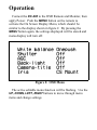
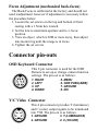
User’s Manual
DAGE-MTI
DC-200
Color Camera
Purchaser’s Record
Model Name: DAGE-MTI DC-200
Serial Number:
Dealer’s Name:
Dealer’s Address:
Dealer’s Phone Number:
Date Purchased:
P.O. Number:
Introduction
The DAGE-MTI DC-200 is a compact color camera based
upon a single 1/3” Interline CCD that provides a high
resolution color image. The CCD employs a state of the art
microlens design to increase the light gathering capability of
the CCD. Digital Signal Processing (DSP) is employed to
provide ultimate video enhancement and function. A
convenient remote setup keypad is included to utilize the On
Screen Display (OSD) commands to set white balance,
shutter, gain, back-light compensation, and an eight character
camera title. The DC-200 also employs automatic edge
enhancement and automatic black balance.
Whether using the camera in a fully automatic mode or in a
manual mode, memory back-up of camera settings allows
you to “set and forget” so you can spend your time
productively obtaining the images needed to perform your
job.
DAGE-MTI offers our customers state-of-the-art video
technology… with an eye on your image.
Installation
MONITOR
VIDEO(COMP) OR Y/C
VIDEO
OSD KEYBOARD
Y/C
TI
-M
E
G
0
DA
20
C
D
DC 12V
12V, 200mA
OSD REMOTE
Figure 1: DC-200 Connections
Power
The red LED located on the camera front lights when
power is supplied to the camera. The camera requires
approximately 200mA at 12VDC. The external power
supply, Dage P/N 738044-02, provides the correct power to
the camera.
Video
The Video BNC connector provides a NTSC (or PAL)
composite video signal to be terminated into 75 Ω. For
improved video performance, the Y/C video output signal
should be used when possible.
Y/C
The Y/C or sometimes referred to as “S Video” connector
provides Y (luminance) and C (color) signals to be
terminated into 75Ω. Because the signals are separate and
not combined like the composite output is, a higher quality
image can be obtained.
OSD Keyboard
The OSD Keyboard connector is used with the OSD
Remote to adjust camera functions such as white balance,
shutter, gain, back light compensation, and the eight character
camera title. The keyboard settings are stored in memory, so
it is only necessary to attach the remote when it is desired to
change settings. The camera Power should be removed
when connecting and disconnecting the remote.
Operation
Connect the DC-200 to the OSD Remote and Monitor, then
apply Power. Push the MENU button on the remote to
activate the On Screen Display Menu, which should be
similar to the display shown in figure 2. By pressing the
MENU button again, the settings displayed will be stored and
menu display will turn off.
Figure 2: OSD Menu
The active editable menu function will be flashing. Use the
UP, DOWN, LEFT, RIGHT buttons to move through menu
items and change settings.
For example, to change the shutter setting from off to auto:
1. Press MENU. WHITE BALANCE will be flashing.
2. Press DOWN. SHUTTER will be flashing.
3. Press RIGHT. OFF will be flashing.
4. Press UP or DOWN to scroll through the available
settings, when AUTO appears, stop.
5. Press MENU to store AUTO and turn off display, or
press LEFT then UP or DOWN to edit other menu
items in a similar matter.
NOTE: When editing MANUAL WHITE BALANCE and
CAMERA TITLE, an additional RIGHT press is needed to
activate the adjustment cursor, then UP/DOWN to change
values and LEFT/RIGHT to change characters as necessary.
White Balance
One Push: By pressing the ONE PUSH (AWB) on the
remote, the camera automatically white balances to the
present scene, then stores setting until ONE PUSH is
pressed again or camera power is turned off. When
camera power is turned back on a ONE PUSH (AWB)
cycle is performed. Pressing the ONE PUSH button
automatically changes the White Balance menu setting
from the previous setting to the ONE PUSH setting.
There must be adequate white area in the scene and
illumination to perform a white balance or the camera
will wait before completing the white balance. The
typical method of white balancing in this mode is to
set the illumination level, place a white object in the
scene (if there is not enough white in scene), then
press ONE PUSH. ONE PUSH (AWB) should be
readjusted when light intensity is changed.
Auto (ATW): This setting places the camera into Auto
Tracking White balance mode. In this mode the
camera continuously measures the object color
temperature and adjusts the white balance
automatically. There must be adequate white area in
the scene and illumination to perform the white
balance.
Manual: The Manual White Balance mode allows the user
to set the white balance. Adjustment is confirmed with
a monitor or vector scope. White balance must be
readjusted when light intensity is changed. When using
the manual adjustment, the green channel is fixed and
the adjustment is made by moving the manual cursor
between blue and red with the UP and DOWN remote
buttons.
3200°K: This fixed color temperature setting is
approximated for indoor incandescent illuminated
subjects.
4600°K: This fixed color temperature setting is
approximated for indoor fluorescent illuminated
subjects.
5600°K: This fixed color temperature setting is
approximated for outdoor illuminated subjects.
Shutter (Electronic Shutter)
Off: Camera is set to standard 1/60 (1/50 PAL) second
shutter. No excessive light shuttering is performed.
Camera gain can be in Auto or Manual (AGC ON or
OFF), but if illumination exceeds the minimum gain of
the camera, overload of the video signal results. If
viewing high illumination scenes, then set shutter to
AUTO or one of the manual settings.
Auto: The exposure time is controlled automatically from
1/60 (1/50 PAL) to 1/10,000 second to obtain the
video level set. Camera gain can be in Auto or Manual
(AGC ON or OFF).
FLCless: (Flicker less) For use in fluorescence
illumination when experiencing flicker problems
associated between fast discharge of fluorescent lamps
and the camera shutter.
Fixed: Six fixed shutter settings are available. 1/250,
1/500, 1/1000, 1/2000, 1/4000, and 1/10,000 second.
AGC
On: The Automatic Gain Control automatically sets the
camera video gain within a 0 to 30 dB range to provide
the correct video output level.
Off: The camera is in a non adjustable manual gain fixed
mode in which the gain is set to minimum. This
setting allows the best possible signal to noise ratio.
Back Light
If the scene has too much Back Light (light behind the
subject) the AGC (Automatic Gain Control) and Auto Shutter
circuits may adjust to the back light instead of the subject.
Use the Pattern which provides the best picture. The Back
Light function works only when AGC and/or Auto Shutter
are on and the illumination level is sufficient for the
automatic circuits to function.
Ptrn.1: Provides highest amount of compensation.
Ptrn.2: Provides moderate amount of compensation.
Off: Provides no Back Light compensation.
Camera Title
The Camera Title provides eight characters of lower or
upper case letters or numbers or symbols. To edit the title,
use the OSD Remote. Press MENU, then DOWN until
CAMERA TITLE flashes, then RIGHT, then DOWN until ON
appears, then RIGHT again. Now the first character of title
will be flashing. Press UP or DOWN to change the character,
then press RIGHT to move to the next character. Repeat this
until all characters have been edited. Press MENU to exit and
store, or LEFT to return to other menu items.
Iris
CCD Iris: This setting sets the camera into AUTO
SHUTTER. (changes shutter setting to auto)
CS Mount: This setting sets the camera SHUTTER to
OFF. (changes shutter setting to off)
Focus Adjustment (mechanical back-focus)
The Back-Focus is calibrated at the factory and should not
need readjustment, however if adjustment is necessary follow
the procedure below:
1. Loosen the set screws on the top and bottom of front
casting with a 1.5mm hex wrench.
2. Set the lens to maximum aperture and to ∞ focus
position.
3. View an object which is 20M or more away, then adjust
lens mount ring until the image is in focus.
4. Tighten the set screws.
Connector pin-outs
OSD Keyboard Connector
This 8 pin connector is used for the OSD
Remote to set-up or change camera function
settings. The pin-out is as follows:
1. RIGHT
2. LEFT
3. UP
4. DOWN
5. MENU
6. ONE PUSH(AWB)
7. GROUND
8. N/C
Y/C Video Connector
This 4 pin connector provides Y (luminance)
and C (color) output signals to be terminated
into 75Ω. The pin-out is as follows:
1. GROUND
2. GROUND
3. Y (LUMINANCE)
4. C (COLOR)
Specifications:
CCD Sensor:
1/3” Interline /w Micro Lenses
NTSC: 768x494 Effective Pixels
PAL: 752x582 Effective Pixels
Sensitivity:
0.015fc, (0.15 lux) /w AGC on
Horizontal Resolution:
480 TVL
Vertical Resolution:
375 TVL-NTSC / 450 TVL-PAL
Signal to Noise:
50dB (AGC off, Y signal)
AGC Range:
30dB
Digital Processing:
9 Bits
Edge Enhancement:
2H Horizontal & Vertical
Memory Back-up:
EEPROM (non volatile)
Auto White Balance:
3000°K to 8000°K
Video Output:
1Vpp, 75Ω comp & Y/C
Gamma Correction:
.45
Electronic Shutter:
Auto from 1/60 to 1/100,000s
Manual Shutter:
1/60, 1/250, 1/500, 1/1000,
1/2000, 1/4000, 1/10,000
Lens Mount:
“C” or “CS”
Camera Mount:
¼-20, Top or Bottom Mount
Dimensions:
2 7/16”W x 2 1/16”H x 2 11/16”L
Weight:
8.6 Ounces
Power:
2.4W (12VDC, 200mA)
Operating Temperature: 0°C to +50°C
Troubleshooting
No Picture (Check or try the following):
1. Camera Power On?
a. External Power Supply Attached?
b. AC Power On?
c. LED on Camera Front On?
2. Monitor Connected to Camera Video Output?
a. Monitor Power On?
3. Light Level Too Low?
a. Open Camera Lens.
b. Set Camera Shutter to Auto or Off.
c. Set Camera AGC to On.
Picture Saturated (Check or try the following):
1. Video Output Cable Terminated Into 75Ω?
2. Light Level Too High?
a. Reduce Lens Setting.
b. Set Camera Shutter to Auto.
c. Set Back-Light Compensation to Off.
Warranty
The DAGE-MTI DC-200 is warranted to be free of
defects in material and workmanship in normal use for a
period of one year from the original date of purchase from
DAGE-MTI.
This warranty does not apply to units which have been
subject to abuse, neglect, accident, improper installation, or
on which the serial number has been removed or damaged.
Units that have been altered without the prior permission of
DAGE-MTI are not covered by this warranty.
This warranty does not apply to other equipment furnished
by DAGE-MTI, which is listed or otherwise identified as
manufactured by another and therefore shall be covered by
the other manufactures’ applicable warranty.
Limitations
1. This warranty is valid only if the malfunctioning unit is
returned to DAGE-MTI service depot. This warranty does
not cover on-location service. If warranty work is needed,
the following should be contacted:
DAGE-MTI, INC.
Customer Service
701 N. Roeske Ave.
Michigan City, IN 46360
(219) 872-5514
Fax: (219) 872-5559
[email protected]
2. This warranty does not cover:
a. Problems caused by or inflicted upon associated
equipment such as digitizing systems, video tape
recorders, cameras, microscopes, etc.
b. Damage caused by accident, misuse, improper power
source, fire, flood, lightning, other acts of God, war,
and repair or alteration by other than a DAGE-MTI
authorized service organization.
c. Labor or incurred charges required in removing or
installing the Product, down time, failure of the
Product to perform properly, and any consequential
damages.
d. Transit damage.
3. Unit must be properly packaged (in original packing, if
possible) when being returned under warranty.
DAGE-MTI Inc.
701 N. Roeske Ave.
Michigan City, IN 46360
(219) 872-5514
Fax: (219) 872-5559
E-mail: [email protected]
http://www.dagemti.com
970204-01
8/5/02