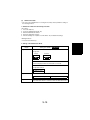
1
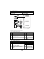
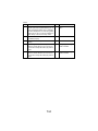
Return to Main Form
Return to Service Form
Exit Program
Di450/Di550
SERVICE MANUAL
[FIELD SERVICE]
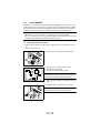
Safety Precautions for Inspection and Service
When performing inspection and service procedures, observe the following precautions to
prevent accidents and ensure utmost safety.
✽ Depending on the model, some of the precautions given in the following do not apply.
Different markings are used to denote specific meanings as detailed below.
WARNING
CAUTION
Indicates a potentially hazardous situation which, if not avoided,
could result in death or serious injury.
Indicates a potentially hazardous situation which, if not avoided,
may result in minor or moderate injury. It may also be used to
alert against unsafe practices.
The following graphic symbols are used to give instructions that need to be observed.
Used to call the service technician’s attention to what is graphically represented
inside the marking (including a warning).
Used to prohibit the service technician’s from doing what is graphically represented inside the marking.
Used to instruct the service technician’s to do what is graphically represented
inside the marking.
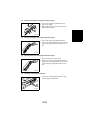
WARNING
1. Always observe precautions.
• Parts requiring special attention in this product will include a label containing the
mark shown on the left plus precautionary notes. Be sure to observe the precautions.
• Be sure to observe the “Safety Information” given in the Operator’s Manual.
2. Before starting the procedures, be sure to unplug the power cord.
• This product contains a high-voltage unit and a circuit with a large current
capacity that may cause an electric shock or burn.
• The product also contains parts that can jerk suddenly and cause injury.
• If this product uses a laser, laser beam leakage may cause eye damage or
blindness.
3. Use the specified parts.
• For replacement parts, always use the genuine parts specified in the manufacturer’s parts manual. Installing a wrong or unauthorized part could cause
dielectric breakdown, overload, or undermine safety devices resulting in possible electric shock or fire.
• Replace a blown electrical fuse or thermal fuse with its corresponding genuine
part specified in the manufacturer’s parts manual. Installing a fuse of a different
make or rating could lead to a possible fire. If a thermal fuse blows frequently,
the temperature control system may have a problem and action must be taken
to eliminate the cause of the problem.
P-1
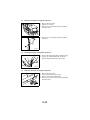
4. Handle the power cord with care and never use a multiple outlet.
• Do not break, crush or otherwise damage the power cord. Placing a heavy
object on the power cord, or pulling or bending it may damage it, resulting in a
possible fire or electric shock.
• Do not use a multiple outlet to which any other appliance or machine is connected.
• Be sure the power outlet meets or exceeds the specified capacity.
5. Be careful with the high-voltage parts.
• A part marked with the symbol shown on the left carries a high voltage. Touching it could result in an electric shock or burn. Be sure to unplug the power cord
before servicing this part or the parts near it.
6. Do not work with wet hands.
• Do not unplug or plug in the power cord, or perform any kind of service or
inspection with wet hands. Doing so could result in an electric shock.
7. Do not touch a high-temperature part.
• A part marked with the symbol shown on the left and other parts such as the
exposure lamp and fusing roller can be very hot while the machine is energized.
Touching them may result in a burn.
• Wait until these parts have cooled down before replacing them or any surrounding parts.
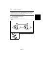
8. Maintain a grounded connection at all times. (This item may not apply in the USA.)
• Be sure to connect the ground wire to the ground terminal even when performing an inspection or repair. Without proper grounding, electrical leakage could
result in an electric shock or fire.
• Never connect the ground wire to a gas pipe, water pipe, telephone ground wire,
or a lightning conductor.
9. Do not remodel the product.
• Modifying this product in a manner not authorized by the manufacturer may
result in a fire or electric shock. If this product uses a laser, laser beam leakage
may cause eye damage or blindness.
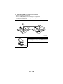
10. Restore all parts and harnesses to their original positions.
• To promote safety and prevent product damage, make sure the harnesses are
returned to their original positions and properly secured in their clamps and saddles in order to avoid hot parts, high-voltage parts, sharp edges, or being
crushed.
• To promote safety, make sure that all tubing and other insulating materials are
returned to their original positions. Make sure that floating components mounted
on the circuit boards are at their correct distance and position off the boards.
P-2
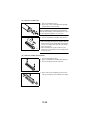
CAUTION
1. Precautions for Service Jobs
• A toothed washer and spring washer, if used originally, must be reinstalled.
Omitting them may result in contact failure which could cause an electric shock
or fire.
• When reassembling parts, make sure that the correct screws (size, type) are
used in the correct places. Using the wrong screw could lead to stripped
threads, poorly secured parts, poor insulating or grounding, and result in a malfunction, electric shock or injury.
• Take great care to avoid personal injury from possible burrs and sharp edges on
the parts, frames and chassis of the product.
• When moving the product or removing an option, use care not to injure your
back or allow your hands to be caught in mechanisms.
2. Precautions for Servicing with Covers and Parts Removed
• Wherever feasible, keep all parts and covers mounted when energizing the
product.
• If energizing the product with a cover removed is absolutely unavoidable, do not
touch any exposed live parts and use care not to allow your clothing to be
caught in the moving parts. Never leave a product in this condition unattended.
• Never place disassembled parts or a container of liquid on the product. Parts
falling into, or the liquid spilling inside, the mechanism could result in an electric
shock or fire.
• Never use a flammable spray near the product. This could result in a fire.
• Make sure the power cord is unplugged before removing or installing circuit
boards or plugging in or unplugging connectors.
• Always use the interlock switch actuating jig to actuate an interlock switch when
a cover is opened or removed. The use of folded paper or some other object
may damage the interlock switch mechanism, possibly resulting in an electric
shock, injury or blindness.
3. Precautions for the Working Environment
• The product must be placed on a flat, level surface that is stable and secure.
• Never place this product or its parts on an unsteady or tilting workbench when
servicing.
• Provide good ventilation at regular intervals if a service job must be done in a
confined space for a long period of time.
• Avoid dusty locations and places exposed to oil or steam.
• Avoid working positions that may block the ventilation ports of the product.
4. Precautions for Handling Batteries
• Replace a rundown battery with the same type as specified in the manufacturer’s parts manual.
• Before installing a new battery, make sure of the correct polarity of the installation or the battery could burst.
• Dispose of used batteries according to the local regulations. Never dispose of
them at the user’s premises or attempt to try to discharge one.
P-3
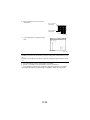
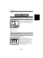
5. Precautions for the Laser Beam (Only for Products Employing a Laser)
• Removing the cover marked with the following caution label could lead to possible exposure to the laser beam, resulting in eye damage or blindness. Be sure
to unplug the power cord before removing this cover.
• If removing this cover while the power is ON is unavoidable, be sure to wear protective laser goggles that meet specifications.
• Make sure that no one enters the room when the machine is in this condition.
• When handling the laser unit, observe the “Precautions for Handling Laser
Equipment.”
1167P001AA
DANGER
Invisible laser radiation when open.
AVOID
DIRECT
TO BEAM
EXPOSURE
0947-7127-01
1144D270AA
P-4
Other Precautions
• To reassemble the product, reverse the order of disassembly unless otherwise specified.
• While the product is energized, do not unplug or plug connectors into the circuit boards
or harnesses.
• The magnet roller generates a strong magnetic field. Do not bring it near a watch, floppy
disk, magnetic card, or CRT tube.
• An air gun and vacuum cleaner generates a strong electrostatic charge that can destroy
the ATDC sensor and other sensors. Before cleaning a component with one of these
devices, be sure to remove all the sensors. Otherwise, use a blower brush and cloth
when cleaning parts.
• When handling circuit boards with MOS ICs, observe the “INSTRUCTIONS FOR HANDLING THE PWBs WITH MOS ICs” (applicable only to the products using MOS ICs).
• The PC Drum is a very delicate component. Observe the precautions given in “HANDLING OF THE PC DRUM” because mishandling may result in serious image problems.
• Note that replacement of a circuit board may call for readjustments or resetting of particular items, or software installation.
• After completing a service job, perform a safety check. Make sure that all parts, wiring
and screws are returned to their original positions.
• Check the area surrounding the service site for any signs of damage, wear or need of
repair.
• Do not pull out the toner hopper while the toner bottle is turning. This could result in a
damaged hopper motor or locking mechanism.
• If the product is to be run with the front door open, make sure that the toner hopper is in
the locked position.
P-5
Used Batteries Precautions
ALL Areas
CAUTION
Danger of explosion if battery is incorrectly replaced.
Replace only with the same or equivalent type recommended by the manufacturer.
Dispose of used batteries according to the manufacturer’s instructions.
Germany
VORSICHT!
Explosionsgefahr bei unsachgemäßem Austausch der Batterie.
Ersatz nur durch denselben oder einen vom Hersteller empfohlenen ähnlichen Typ.
Entsorgung gebrauchter Batterien nach Angaben des Herstellers.
France
ATTENTION
Ily a danger d’explosion s’ily a remplacement incorrec de la batterie.
Remplacer uniquement avec une batterie du meme type ou d’un type équivalent recommande par le constructueur.
Mettre au rebut les batteries usageés conformément aux instructions du fabricant.
Denmark
ADVARSEL!
Lithiumbatteri - Eksplosionsfare ved fejlagtig håndtering Udskiftning må kun ske med batteri af samme fabrikat og type.
Levér det brugte batteri tilbage til leverandøren.
Norway
ADVARSEL
Eksplosjonsfare ved feilaktig skifte av batteri.
Benytt samme batteritype eller en tilsvarende type anbefalt av apparatfabrikanten.
Brukte batterier kasseres i henhold til fabrikantens instruksjoner.
Sweden
VARNING
Explosionsfara vid felaktigt batteribyte.
Använd samma batterityp eller en ekvivalent typ som rekommenderas av apparattillverkaren.
Kassera använt batteri enligt fabrikantens instruktion.
Finland
VAROlTUS
Paristo voi räjähtää, los se on virheellisesti asennettu.
Vaihda paristo ainoastaan laitevalmistajan suosittelemaan tyyppiin. Hävitä Käytetty paristo
valmistajan ohjeiden mukaisesti.
P-6
PRECAUTIONS FOR SERVICE
When performing inspection and service procedures, observe the following precautions to
prevent mishandling of the machine and its parts.
✽ Depending on the model, some of the precautions given in the following do not apply.
Precautions Before Service
• When the user is using a word processor or personal computer from a wall outlet of the
same line, take necessary steps to prevent the circuit breaker from opening due to overloads.
• Never disturb the LAN by breaking or making a network connection, altering termination,
installing or removing networking hardware or software, or shutting down networked
devices without the knowledge and express permission of the network administrator or
the shop supervisor.
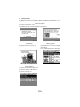
How to Use this Book
1. DIS/REASSEMBLY, ADJUSTMENT
• To reassemble the product, reverse the order of disassembly unless otherwise specified.
2. TROUBLESHOOTING
• If a component on a PWB or any other functional unit including a motor is defective, the
text only instructs you to replace the whole PWB or functional unit and does not give troubleshooting procedures applicable within the defective unit.
• All troubleshooting procedures contained herein assume that there are no breaks in the
harnesses and cords and all connectors are plugged into the right positions.
• The procedures preclude possible malfunctions due to noise and other external causes.
Precautions for Service
• Check the area surrounding the service site for any signs of damage, wear or need of
repair.
• Keep all disassembled parts in good order and keep tools under control so that none will
be lost or damaged.
• After completing a service job, perform a safety check. Make sure that all parts, wiring
and screws are returned to their original positions.
• Do not pull out the toner hopper while the toner bottle is turning. This could result in a
damaged motor or locking mechanism.
• If the product is to be run with the front door open, make sure that the toner hopper is in
the locked position.
• Do not use an air gun or vacuum cleaner for cleaning the ATDC Sensor and other sensors, as they can cause electrostatic destruction. Use a blower brush and cloth. If a unit
containing these sensors is to be cleaned, first remove the sensors from the unit.
PS-1
Precautions for Dis/Reassembly
• Be sure to unplug the copier from the outlet before attempting to service the copier.
• The basic rule is not to operate the copier anytime during disassembly. If it is absolutely
necessary to run the copier with its covers removed, use care not to allow your clothing to
be caught in revolving parts such as the timing belt and gears.
• Before attempting to replace parts and unplug connectors, make sure that the power
cord of the copier has been unplugged from the wall outlet.
• Be sure to use the Interlock Switch Actuating Jig whenever it is necessary to actuate the
Interlock Switch with the covers left open or removed.
• Do not plug in or unplug print jacks on the PWB or connect or disconnect the PWB connectors while power is being supplied to the copier.
• Never use flammable sprays near the copier.
• A battery (lithium, nickel-cadmium, etc.) is used in this machine. Do not charge or short
circuit it and make sure of the correct polarity at replacement.
• A used battery should be disposed of according to the local regulations and never be discarded casually or left unattended at the user's premises.
• When reassembling parts, make sure that the correct screws (size, type) and toothed
washer are used in the correct places.
• If it becomes necessary to replace the thermal fuse or any other fuse mounted on a
board, be sure to use one of the rating marked on the blown fuse. Always note the rating
marked on the fuse, as the rating and mounting site or number used are subject to
change without notice.
Precautions for Circuit Inspection
• Never create a closed circuit across connector pins except those specified in the text and
on the printed circuit.
• When creating a closed circuit and measuring a voltage across connector pins specified
in the text, be sure to use the GND wire.
PS-2
Handling of PWBs
1. During Transportation/Storage:
• During transportation or when in storage, new P.W. Boards must not be indiscriminately
removed from their protective conductive bags.
• Do not store or place P.W. Boards in a location exposed to direct sunlight and high temperature.
• When it becomes absolutely necessary to remove a Board from its conductive bag or
case, always place it on its conductive mat in an area as free as possible from static electricity.
• Do not touch the pins of the ICs with your bare hands.
• Protect the PWBs from any external force so that they are not bent or damaged.
2. During Inspection/Replacement:
• Avoid checking the IC directly with a multimeter; use connectors on the Board.
• Never create a closed circuit across IC pins with a metal tool.
• Before unplugging connectors from the P.W. Boards, make sure that the power cord has
been unplugged from the outlet.
• When removing a Board from its conductive bag or conductive case, do not touch the
pins of the ICs or the printed pattern. Place it in position by holding only the edges of the
Board.
• When touching the PWB, wear a wrist strap and connect its cord to a securely grounded
place whenever possible. If you cannot wear a wrist strap, touch a metal part to discharge static electricity before touching the PWB.
• Note that replacement of a PWB may call for readjustments or resetting of particular
items.
Handling of Other Parts
• The magnet roller generates a strong magnetic field. Do not bring it near a watch, floppy
disk, magnetic card, or CRT tube.
PS-3
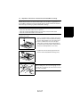
Handling of the PC Drum
✽ Only for Products Not Employing an Imaging Cartridge.
1. During Transportation/Storage:
• Use the specified carton whenever moving or storing the PC Drum.
• The storage temperature is in the range between –20°C and +40°C.
• In summer, avoid leaving the PC Drum in a car for a long time.
2. Handling:
• Ensure that the correct PC Drum is used.
• Whenever the PC Drum has been removed from the copier, store it in its carton or protect
it with a Drum Cloth.
• The PC Drum exhibits greatest light fatigue after being exposed to strong light over an
extended period of time. Never, therefore, expose it to direct sunlight.
• Use care not to contaminate the surface of the PC Drum with oil-base solvent, fingerprints, and other foreign matter.
• Do not scratch the surface of the PC Drum.
• Do not apply chemicals to the surface of the PC Drum.
• Do not attempt to wipe clean the surface of the PC Drum.
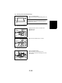
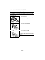
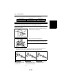
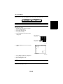
If, however, the surface is contaminated with fingerprints, clean it using the following procedure.
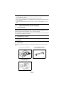
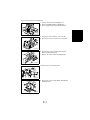
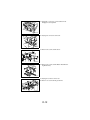
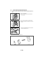
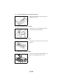
1. Place the PC Drum into one half of its carton.
1076D001
1076D002
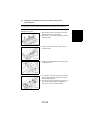
2. Gently wipe the residual toner off the surface of the
PC Drum with a dry, Dust-Free Cotton Pad.
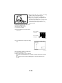
A. Turn the PC Drum so that the area of its surface on
which the line of toner left by the Cleaning Blade is
present is facing straight up. Wipe the surface in
one continuous movement from the rear edge of
the PC Drum to the front edge and off the surface
of the PC Drum.
B. Turn the PC Drum slightly and wipe the newly
exposed surface area with a CLEAN face of the
Dust-Free Cotton Pad. Repeat this procedure until
the entire surface of the PC Drum has been thoroughly cleaned.
✽ At this time, always use a CLEAN face of the dry
Dust-Free Cotton Pad until no toner is evident on the
face of the Pad after wiping.
PS-4
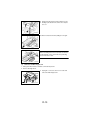
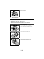
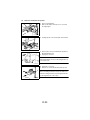
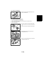
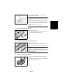
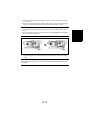
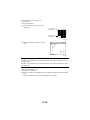
3. Soak a small amount of either ethyl alcohol or isopropyl alcohol into a clean, unused Dust-Free Cotton Pad which has been folded over into quarters.
Now, wipe the surface of the PC Drum in one continuous movement from its rear edge to its front
edge and off its surface one to two times.
✽ Never move the Pad back and forth.
1076D003
4. Using the SAME face of the Pad, repeat the procedure explained in the latter half of step 3 until the
entire surface of the PC Drum has been wiped.
Always OVERLAP the areas when wiping. Two
complete turns of the PC Drum would be appropriate for cleaning.
1076D004
NOTES
• Even when the PC Drum is only locally dirtied, wipe the entire surface.
• Do not expose the PC Drum to direct sunlight. Clean it as quickly as possible even under
interior illumination.
• If dirt remains after cleaning, repeat the entire procedure from the beginning one more
time.
Handling of the Imaging Cartridge
✽ Only for Products Employing an Imaging Cartridge.
1. During Transportation/Storage:
• The storage temperature is in the range between –20°C and +40°C (-4°F and +104°F).
• In summer, avoid leaving the Imaging Cartridge in a car for a long time.
2. Handling:
• Store the Imaging Cartridge in a place that is not exposed to direct sunlight.
3. Precautionary Information on the PC Drum Inside the Imaging Cartridge:
• Use care not to contaminate the surface of the PC Drum with oil-base solvent, fingerprints, and other foreign matter.
• Do not scratch the surface of the PC Drum.
• Do not attempt to wipe clean the surface of the PC Drum.
PS-5
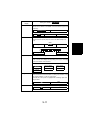
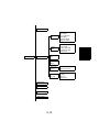
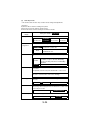
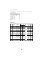
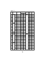
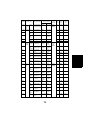
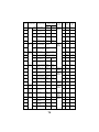
DIS/REASSEMBLY,
ADJUSTMENT
%%$
!
"#$% !
&' ()
#'#*+ ))%,')
,$
,#'!
%- '
&' ()
./.
0
0
1
2
3
4,5#+
,6
%- $%
7
4,5#+
,6
%- 8+%
9"#))
$%
7
4,5#+
,6
%- 8&%,$
$%
7
4,5#+
,6
%- #$
,"" '
$%
:
; 4,5#+
,6
%- $%
3 4,5#+
,6
%- $%
;
< 4,5#+
,6
%- 5 +,"$=
$%
<
> 4,5#+
,6
%- 8*
,"" '
$%
<
? 4,5#+
,6
%- 8)$=
$%
<
7 4,5#+
,6
%- "" '
6%
,,'
@%/8"+ @
(%&-$=
$%
>
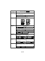
; /
?
4,5#+
,6
%- #" '
#A "
,++0
#" '
!
,++
#$!
#" '
"#'#%,'
,++
))9
?
+ #$$=
,6
%- #" '
#A "
,++
#$!
#" '
!
,++
7
+ #$$=
,6
%- #" '
"#'#%,'
,++
7
; 4,5#+
,6
%- '#( '
6%"
,%,'
:
3 4,5#+
,6
%- "" '
#$!
,( '
'#$)",'%
,++ ')
< + #$$=
,6
%- "" '
'#$)",'%
,++ '
> + #$$=
,6
%- ,( '
'#$)",'%
,++ '
? + #$$=
,6
%- '%&#+
'#$)",'%
,++ ')
;
7 4,5#+
,6
%- 9$&-',$B$=
,++ '
;
: + #$$=
,6
%- "" '
9$&-',$B$=
,++ '
<
4,5#+
,6
%- ,( '
9$&-',$B$=
,++ '
<
+ #$$=
,6
%- ,( '
9$&-',$B$=
,++ '
>
4,5#+
,6
%- 9$&-',$B$=
#" '
8)%
4,5 '
>
; 4,5#+
,6
%- '#$)",'%
#" '
8)%
4,5 '
>
3 + #$$=
,6
%- #" '
8)%
4,5 '
?
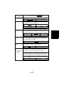
< )#)) 4*+9
,6
%- 8&%,$
$%
?
> )#)) 4*+9
,6
%- 8+%
9"#))
$%
7
? + #$$=
,6
%- 8+%
9"#))
#" '
#A "
,++/#" '
!
,++
7 + #$$=
,6
%- 8+%
9"#))
#" '
"#'#%,'
,++
))9
3 + #$$=
,6
%- '=$#+
+#))
#$!
+#))
+ #$$=
,6
%- '',')
+ #$$=
,6
%- $)
; + #$$=
,6
%- &#$$ '
#+)/*8)-$=)
3 + #$$=
,6
%- +#))
< 4,5#+
,6
%- &#$$ '
> 4,5#+
,6
%- @",)8' #4"
;
? 4,5#+
,6
%- +#))
3
7 4,5#+
,6
%- &#$$ '
'5 #*+ 3
: $!$=
,6
%- &#$$ '
'5 #*+ <
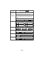
< ;
4,5 ,6
%- 5 +,"$=
$%
;
+ #$$=
,6
%- 5 +," '
&#%% '$=
' 5 $%,$
+#% ;;
+ #$$=
,6
%- ,)%,$$=
,++#')
;;
; + #$$=
,6
%- ,$ '
$%)"++
'#"
;;
3 "+#& 4 $%
,6
%- + #$$=
+#! ;;
< "+#& 4 $%
,6
%- 5 +," '
;<
> + #$$=
,6
%- $),'
,#'!
;>
? + #$$=
,6
%- '84
#" '
"#'#%,'
$= ')
;>
7 4,5#+
,6
%- ,$ '
$%)"++
#+
;>
: + #$$=
,6
%- ,$ '
$%)"++
#+
;?
4,5#+
,6
%- #$
'#) #4"
;?
+ #$$=
,6
%- #$
'#) #4"
+% '
;?
4,5#+
,6
%- B,$ +% '
'84
-#'= ,',$#
;7
; 4,5#+
,6
%- B,$ +% '
4#= '#$)6 '/#" '
"#'#%,'
,',$#)
;7
3 4,5#+
,6
%- ,$ '
,++ &%$=
,%%+ ;7
> /
3:
4,5#+
,6
%- '84
-#'= ,',$#
3:
+ #$$=
,6
%- '84
-#'= ,',$#
,8)$=
3:
+ #$$=
,6
%- '84
-#'= ,',$#
'!
)-
3
; + #$$=
,6
%- ,4*
+ &%',! 3
3 4,5#+
,6
%- 4#= '#$)6 '/#" '
"#'#%,'
,',$#)
3
< + #$$=
,6
%- 4#= '#$)6 '
,',$#
' 3
> 4,5#+
,6
%- 4#= '#$)6 '
,',$#
' 3
? + #$$=
,6
%- #" '
"#'#%,'
,',$#
' 3
7 4,5#+
,6
%- #" '
"#'#%,'
,',$#
' 3;
: + #$$=
,6
%- 4#= '#$)6 '/#" '
"#'#%,'
,',$#)
,8)$=
3;
+ #$$=
,6
%- ' 4#= '#$)6 '
8! +#% 33
? 3<
)#)) 4*+9
,6
%- 8)$=
$%
3<
4,5#+
,6
%- "" '
8)$=
#" '
"#'#%,'
$= ')
<
+ #$$=
,6
%- "" '
8)$=
#" '
"#'#%,'
$= ')
<
; + #$$=
,6
%- ,( '
8)$=
#" '
"#'#%,'
$= ')
<
3 + #$$=
,6
%- $%'#$& 8! +#% <
< 4,5#+
,6
%- "" '
8)$=
,++ '
- '4)%,'
<
> + #$$=
,6
%- "" '
8)$=
,++ '
- '4)%,'
<
? 4,5#+
,6
%- ,( '
8)$=
,++ '
- '4)%,'
<
7 + #$$=
,6
%- ,( '
8)$=
,++ '
- '4)%,'
<
: 4,5#+
,6
%- "" '
8)$=
,++ '
- '4,)%#%
<
+ #$$=
,6
%- "" '
8)$=
,++ '
- '4,)%#%
<
4,5#+
,6
%- *
,++ '
<;
4,5#+
,6
%- *
' ))8' ,++ '
<;
; 4,5#+
,6
%- )6 !
4,5#+
$,*
8)-$=
<3
3 4,5#+
,6
%- 8)$=
$%
'5 ,8"+$=
#'
<3
7 <3
+ #$$=
,6
%- 8'$,5 '
,++ '0
'#$)",'%
,++ ')
<3
C
<<
C
C
<<
C
<>
C
<?
&',)(%&- )
<?
!D8)%4 $%
,6
',$%
,,'
$% '+,&A
(%&-
<7
; C
>:
!D8)%4 $%
,6
%- 8&%,$
'5 4$=
+%
>:
!D8)%4 $%
,6
%- 5 +,"$=
$%
'5 4$=
+%
>:
!D8)%4 $%
,6
%- &#$$ '
,%,'
4$=
+%
>
3 C
>
!D8)%4 $%
,6
#$8#+
!
#" '
&A"
,+ $,!
>
!D8)%4 $%
,6
8'$,5 '
,++ '
%'#&%,$
,+ $,!
>;
!D8)%4 $%
,6
@%/8"+ @
(%&-$=
,+ $,!
>3
; ,)%,$$=
,6
%- '84
#" '
"#'#%,'
$= ')
"#'#%,'
$= '
,+ $,!
><
3 !D8)%4 $%
,6
8'$,5 '
,8% (%&-$=
,+ $,!
>>
< C
>?
&& ))$=
%- &-
"
,! >?
&& ))$=
%- !D8)%
,! >?
> /
C
>7
,8&-
#$ +
!D
>7
'=
B !D8)%
?:
?
$),'
?
; 3
$),'
?
3 =)%'#%,$
?
< =)%'#%,$
?3
> #!
!= '#) ?>
? '#+
!= '#) ?7
7 ,,"
!D8)%4 $%
7
: '#)8' !%-
7
E,,4
73
E,,4
7>
&#+ 77
; &#+ :
? C
:
;
!D8)%4 $%
,6
%- 6 ' $& ,)%,$
,6
#&-
'#( '
:
!D8)%4 $%
,6
%- 6 ' $& ,)%,$
,6
%- 8+%
9"#))
'#9
:3
!D8)%4 $%
,6
%- "" '
=-%
,,'
8+%
9"#))
$%
:<
!D8)%4 $%
,6
%- ,)%,$
,6
%- &#$$ '
#$!
$!/'!
'',')
#''#= :>
3 !D8)%4 $%
,6
%- $!/'!
'',')
#''#= ))9
6,'
#'#++ +
+=$4 $%
:?
< !D8)%4 $%
,6
%- #"
%( $
%- ,&%,'
+#! #$!
+ 5 ,++ '
!D8)%4 $%
:7
; :
; .
:
; E
; .
('%$=
%- #)% '
,#'!
#%#
('%$=
%- 4#= ',& ))$=
,#'!
#%#
('%$=
%- ,#'!
#%#
,"%,$
3
; ('%$=
%- #)% '
,#'!0
4#= ',& ))$=
,#'!0
#$!
,#'!
"%,$
48+%#$ ,8)+9
<
;; >
4,8$%$=
,$
%- #)% '
,#'!
>
4,8$%$=
,$
%- 4#= ',& ))$=
,#'!
?
5
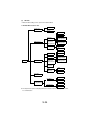
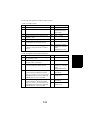
1.
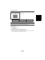
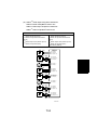
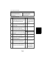
SERVICE INSTRUCTIONS
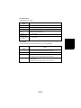
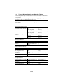
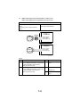
1-1.
IDENTIFICATION OF FUSES AND CIRCUIT BREAKERS
Inverter Board
INV 250 V 2 A (F1)
DC Power Supply Main
PU1 <100 V Areas>
125 V 15 A (F1)
125 V 4 A
(F2)
125 V 15 A (F3)
125 V 6.3 A (F4)
<200 V Areas>
250 V 8 A
(F1)
250 V 3.15 A (F2)
250 V 8 A
(F3)
250 V 3.15 A (F4)
DC Power Supply Sub
PU2 <100 V Areas>
125 V 4 A
(F1)
250 V 3.15 A (F2)
<200 V Areas>
250 V 3.15 A (F1)
250 V 1.60 A (F2)
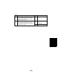
1-2.
Power Supply Board
PWB-C 250 V 4 A (6 pcs.)
Upper Fusing Roller Thermostat
TS1 250 V 10 A
4002M014AB
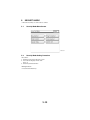
PRECAUTIONS FOR HANDLING THE LASER EQUIPMENT
• The laser used in this copier is a semiconductor laser having the following specifications.
Max. power: 5 mW × 2
Output wavelength: 770 to 800 nm
• When laser protective goggles are to be used, select ones with a lens conforming to the
above specifications.
• When a disassembly job needs to be performed in the laser beam path, such as when
working around the printerhead and PC Drum, be sure first to turn the copier OFF.
• If the job requires that the copier be left ON, take off your watch and ring and wear laser
protective goggles.
• A highly reflective tool can be dangerous if it is brought into the laser beam path. Use
utmost care when handling tools on the user’s premises.
• The printerhead is not maintainable in the field. It is to be replaced as an assembly
including the control board. Never, therefore, attempt to remove the laser diode or adjust
trimmers on the control board.
D-1
NOTES
• The Organic Photoconductor Drum is softer than CdS and Selenium Drums and is therefore susceptible to scratches.
• Even when the PC Drum is only locally dirtied, wipe the entire surface.
• Do not expose the PC Drum to direct sunlight. Clean it as quickly as possible even under
interior illumination.
• If dirt remains after cleaning, repeat the entire procedure from the beginning one more
time.
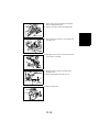
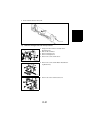
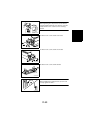
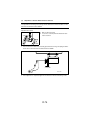
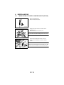
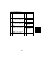
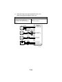
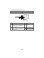
1-3.
(1)
PARTS WHICH MUST NOT BE TOUCHED
Red painted Screws
Purpose of Application of Red Paint
Red painted screws show that the assembly or unit secured can only be adjusted or set at
the factory and should not be adjusted, set, or removed in the field.
Note that when two or more screws are used on the part in questions, only one representative screw may be marked with red paint.
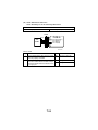
(2)
Variable Resistors on Board
Do not turn the variable resistors on boards for which no adjusting instructions are given in
“ADJUSTMENT.”
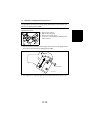
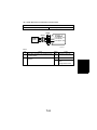
(3)
Other Screws
Although not marked with red paint, the following screws must not be loosened or readjusted.
8 screws on the PH Unit Cover
4 screws on the Image Transfer/
Paper Separator Coronas
4002D104AB
4002D256AA
2 screws on the Separator
Finger Solenoid
4002D257AA
D-2
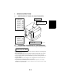
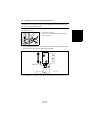
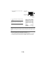
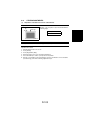
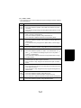
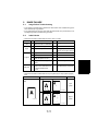
2.
DISASSEMBLY/REASSEMBLY
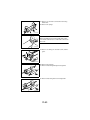
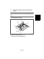
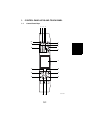
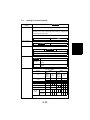
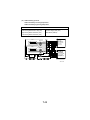
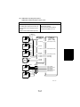
2-1.
DOORS, COVERS, AND EXTERIOR PARTS: IDENTIFICATION
AND REMOVAL PROCEDURES
12
1
2
3
4
5
11
10
6
9
7
8
4002D025AC
13
18
17
14
16
15
4002D026AC
D-3
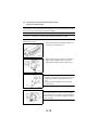
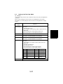
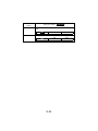
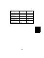
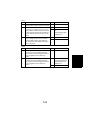
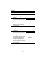
No.
Part Name
Removal Procedure
1
Original Glass
Remove No.3.
2
EDH Glass
Remove No.3.
3
EDH Glass Holder Raise No.13. → Remove four EDH Glass Holder mounting
screws.
4
Control Panel
Raise No.13. → Swing down No.5. → Remove No.18. → Remove
No.11. → Remove five Control Panel mounting screws. → Unplug
two connectors.
5
Front Door
Swing down the Front Door. → Remove two Front Door hinge
shafts. → Remove two belt mounting screws inside the Front
Door.
Slide out the drawer. → Remove one screw and the right stopper.
→ Pressing the tab on the left rail, pull out the drawer.
6
1st Drawer
7
2nd Drawer
8
Middle Left Door
Remove No.11. → Remove two Middle Left Door mounting
screws.
9
Upper Left Door
(Exit/Duplex
Switching Unit)
☞ D-17
10 Filter Cover
Unhook one tab on the Filter Cover.
11 Left Cover
Slide out No.6. → Swing down No.5. → Remove seven Left Cover
mounting screws.
12 Rear Upper Cover Remove No.13. → Remove No.11. → Remove No.18. → Remove
two Rear Upper Cover mounting screws.
13 Original Cover
Remove the Original Cover by pulling up.
14 Rear Cover
Remove nine Rear Cover mounting screws.
15 Connector Cover
Remove one Connector Cover mounting screws.
16 Upper Right Door ☞ D-9
(Multi Bypass
Unit)
17 Counter Cover
Unhook two tabs on the Counter Cover.
18 Right Cover
Slide out No.6. → Swing down No.5. → Open No.16. → Open the
Multi Bypass Table. → Remove seven Right Cover mounting
screws.
D-4
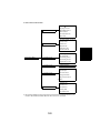
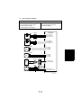
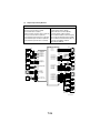
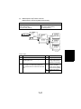
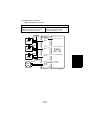
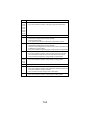
2-2.
REMOVAL OF CIRCUIT BOARDS AND OTHER ELECTRICAL
COMPONENTS
• When removing a circuit board or other electrical component, refer to “Handling of
PWBs” and follow the corresponding removal procedures.
• The removal procedures given in the following omit the removal of connectors and
screws securing the circuit board support or circuit board.
• Where it is absolutely necessary to touch the ICs and other electrical components on the
board, be sure to ground your body.
INV
PWB-A
PWB-IC
PWB-B
PWB-IA
PWB-R
UN2
PWB-I1
PWB-I2
UN1
PU1
PWB-G
PU2
PWB-S
HV1
PWB-C
4002M013AC
D-5
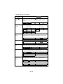
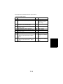
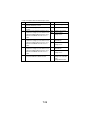
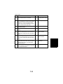
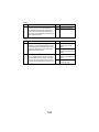
Symbol
Part Name
Removal Procedure
INV
Inverter Board
Remove the Scanner. → Unplug two connectors and
remove two screws and the Inverter Board Mounting
Bracket Assy. → INV
PWB-A
Master Board
Remove the Right Cover. → Remove the Rear Cover. →
Remove three screws and the Cover. → Remove four
screws and the Cover. → PWB-A
PWB-B
Image Processing ☞ D-7
Board
PWB-C
Power Supply
Board
Remove the Right Cover. → Remove the Rear Cover. →
Remove six screws and the Board Cover. → PWB-C
PWB-G
AIDC Sensor
Board
☞ D-41
PWB-I1
Paper Size
Remove four screws and the PC Drum Charge/Developing
Detecting Board 1 Bias HV Mountaing Bracket Assy. → Remove two screws
and the Board Cover. → PWB-I
Paper Size
PWB-I2
Detecting Board 2
PWB-IC
SCP Board
Remove the Rear Upper Cover. → PWB-IC
PWB-M
Memory Board
Remove the Original Glass. → Remove four screws and the
IR Base Plate Left Cover. → PWB-M
PWB-R
HDD Power Supply Board
Remove the Rear Cover. → Remove the Left Cover. →
Remove three screws and the HDD Mounting Bracket Assy.
→ PWB-R
PWB-S
Tech. Rep. Setting Swing down the Front Door. → Remove the Left Cover. →
Switches Board
Remove four screws and the Cover. → PWB-S
UN1
Control Panel
Remove the Control Panel Unit. → UN1
UN2
ATDC Sensor
☞ D-41
PU1
DC Power Supply
Main
Remove the Rear Cover. → Remove six screws and the
Board Cover. → PU1
PU2
DC Power Supply
Sub
Remove the Rear Cover. → Remove the Left Cover. →
Remove three screws and the DC Power Supply Sub
Mounting Bracket Assy. → PU2
HV1
PC Drum Charge/ Remove the Rear Cover. → Remove six screws and the
Developing Bias
Board Cover. → Remove ten screws and the DC Power
HV
Supply Main Mounting Bracket Assy. → HV1
NOTE
PWB-M and PWB-R: optional on both the 45-cpm copier and 55-cpm copier.
D-6
Removal of the Image Processing Board
1. Remove the Rear Cover and Right Cover.
2. Remove the Original Glass and EDH Glass.
3. Remove eight screws and the CCD Unit Cover.
4002D043AB
4. Remove four screws and the cover on the left.
5. Remove three screws and the cover on the right.
4002D044AC
6. Remove three screws and the PH Cooling Fan
Motor mounting bracket Assy.
7. Remove six screws and the mounting bracket.
4002D046AB
8. Remove five screws and the Cover.
Cover
4002D238AC
9. Remove five screws and the Master Board Mounting Bracket Assy.
4002D069AC
D-7
10. Unplug two connectors, one flat cable.
4002D034AC
11. Unplug five connectors, two flat cables.
12. Remove the harness from the edge cover.
4002D258AB
13. Unplug four connectors.
14. Remove five screws and the Imaging Processing
Board Mounting Bracket Assy.
4002D515AA
15. Remove ten screws and the Imaging Processing
Board.
4002D516AA
D-8
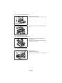
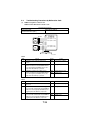
2-3.
(1)
Removal of the Unit
Removal of the Multi Bypass Unit
1. Open the Upper Right Door.
2. Remove two connectors and the cover.
3. Unplug two connectors.
4002D027AD
4. Remove two screws and the Upper Right Cover.
NOTE
When reinstalling the Upper Right Cover, Adjustment
of the Upper Right Door (Multi Bypass Unit).
☞ D-106
4002D028AB
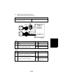
(2)
1.
2.
3.
4.
Removal of the Suction Unit
Swing down the Front Door and slide out the Developer Unit.
Remove the Paper Dust Remover Assy.
Slide out the Fusing Unit.
Slide out the 1st and 2nd Drawers.
5. Unplug two connectors from lower end of the Suction Unit.
4002D029AA
6. Swing the Transport Section Release Lever back to
its original position.
7. Pressing down the Transfer/Paper Separator Coronas Unit, pull out of the copier.
4002D030AB
D-9
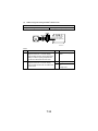
8. Swing down the Transport Section Release Lever.
9. Holding up the Suction Unit, remove the compression coil.
4002D031AD
10. Remove the Suction Unit by sliding it to the right.
1136D101AA
NOTE
When reinstalling the Suction Unit, make sure that two
positioning pins on the copier fit into the positioning
holes in the Suction Unit.
1134D028AA
(3)
Removal of the Main Hopper Unit
1. Swing down the Front Door and slide out the Developer Unit.
2. Remove the Right Cover.
3. Unplug two connectors, remove four screws and
remove the Main Hopper Unit.
4002D032AD
D-10
(4)
Removal of the IR Unit
1. Swing down the Front Door and slide out the Developer Unit.
2. Remove the Right Door, Left Door, Rear Upper Cover, Rear Cover and Control Panel.
3. Slide out the Fusing Unit.
4. Remove four screws and the Cover.
NOTE
Do not remove the belt mounting screw on the cover.
4002D196AC
5. Unplug two connectors, remove four screws and
remove the Main Hopper Unit.
4002D032AD
6. Remove three screws and the PH Cooling Fan
Motor mounting bracket Assy.
7. Remove six screws and the mounting bracket.
4002D046AB
8. Remove the Original Grass and EDH Glass.
9. Remove eight screws and the CCD Unit Cover.
4002D043AB
10. Remove four screws and the Cover.
4002D033AB
D-11
11. Unplug two connectors, one flat cable from the
Imaging Processing Board.
4002D034AC
12. Unplug four connectors at the front.
4002D035AD
13. Remove five screws and the Cover.
Cover
4002D238AC
14. Remove five screws and the Master Board Mounting Bracket Assy.
4002D069AC
15. Unplug ten connectors in the rear.
16. Remove one screw and the ground wire.
4002D036AC
D-12
17. Remove two screws and the relay connector.
4002D037AB
18. Remove four screws and the right mounting
bracket.
4002D038AC
19. Remove four screws and the left mounting bracket.
4002D039AC
20. Remove five screws that secure the IR Unit on the
front side.
4002D040AD
21. Remove four screws that secure the IR Unit in the
rear.
4002D041AB
D-13
22. Remove the IR Unit.
4002D042AB
(5)
Removal of the PH Unit
NOTES
• Do not place the PH Unit upside down, tilt it excessively, or subject it to excessive shock.
• Replace the PH Unit as one unit.
• NEVER attempt to disassemble or adjust the PH Unit.
• Whenever the PH Unit has been removed, make the following adjustments:
Lead/Trail Edge Erase and Registration (CD/FD).
1. Remove the Right Cover.
2. Remove the Original Glass and EDH Glass.
3. Remove eight screws and the CCD Unit Cover.
4002D043AB
4. Remove three screws and the cover.
4002D260AA
5. Unplug two connectors, two flat cables.
6. Remove the harness from the edge cover.
4002D045AB
D-14
7. Remove three screws and the PH Cooling Fan
Motor mounting bracket Assy.
8. Remove six screws and the mounting bracket.
4002D046AB
9. Remove the harness from two cord clamps and
one edge cover.
4002D047AC
10. Unplug two relay connectors and remove the harness from the cord clamp.
4002D048AB
11. Swing down the Front Door and slide out the
Developer Unit.
12. Remove two thumbscrews and one bolt.
4002D049AB
13. Remove the PH Unit.
4002D050AB
D-15
(6)
Removal of the Developing Unit
1. Swing down the Front Door.
2. Swing down the Transport Section Release Lever.
4002D051AB
3. Loosen two screws and remove the Developing
Unit.
4002U072AB
(7)
Removal of the Sub Hopper Unit
1. Swing down the Front Door and slide out the
Developing Unit.
2. Unplug one connector and remove three screws
and the Sub Hopper Unit.
4002D053AA
(8)
Removal of the Fusing Unit
1. Open the Left Door.
2. Swing Down the Front Door.
3. Remove one screw and slide out the Fusing Unit.
4002D054AC
D-16
(9)
Removal of the Upper Left Door (Exit/Duplex Switching Unit)
1. Swing down the Front Cover and slide out the Fusing Unit.
2. Remove the cable from the spring.
4002D261AA
3.
4.
5.
6.
Remove the Rear Cover.
Open the Upper Left Door.
Remove the Left Cover.
Unplug one connector and remove the harness
from the edge cover.
7. Remove one screw, holding bracket, and the band.
4002D055AC
8. Remove one screw and the holding bracket.
9. Remove the Upper Left Door.
4002D056AE
D-17
2-4.
(1)
PAPER TAKE-UP/TRANSPORT SECTION
Removal of the Paper Take-Up Roll, Paper Feed Roll and Paper Separator Roll
Assy.
1. Remove the Right Door.
2. Remove one screw and the Paper Guide Plate
from each drawer.
4002D057AB
3. Remove the Paper Separator Roll/Paper Guide
Plate Assy. by turning it about 90 in the direction of
the arrow.
4002D058AC
4. Loosen one screw and remove the Paper Separator Roll Mounting Bracket Assy.
4002D059AE
5. Disassemble the Paper Separator Roll Assy.
4002D060AB
D-18
6. Unbending one tab of the holder, remove the
holder.
4002D061AB
7. Remove the Paper Take-Up Roll and Paper Feed
Roll.
4002D062AB
(2)
Cleaning of the Paper Take-Up Roll and Paper Feed Roll
1. Remove the Paper Separator Roll Mounting
Bracket Assy.
2. Using a soft cloth dampened with alcohol, wipe
each roll clean of dirt.
4002D063AA
(3)
Cleaning of the Paper Separator Roll
1. Remove the Paper Separator Roll Mounting
Bracket Assy.
2. Using a soft cloth dampened with alcohol, clean
the Paper Separator Roll.
4640D009AA
D-19
(4)
Removal of the Drawer Lift-Up Motor
1. Remove the Right Door.
2. Slide out the drawer and remove one screw and
the right stopper.
4002D065AB
3. Pushing the tab on the left rail, pull out the drawer.
4002D066AC
4. Remove three screws and the Drawer Set Sensor
Mounting Bracket Assy.
5. Unplug one connector.
NOTE
Reinstall the Drawer Set Sensor Mounting Bracket as
you hold the lever.
4002D067AB
6. Unplug two connectors.
7. Remove one screw and the Drawer Lift-Up Unit.
NOTE
When reinstalling the Drawer Lift-Up Unit, make sure
that the mounting bracket is properly aligned with the
positioning dowel pin on the copier.
4002D262AA
D-20
8. Disassemble the Drawer Lift-Up Unit.
1156D022AA
(5)
Removal of the Upper and Lower Transport Rollers
1. Swing down the Front Door and slide out the
Developing Unit.
2. Slide out the 1st Drawer.
3. Remove the Rear Cover.
4. Remove the Right Cover.
5. Remove five screws and the Cover.
Cover
4002D238AC
6. Remove five screws and the Master Board Mounting Bracket Assy.
4002D069AC
7. Remove six screws and the board cover.
4002D068AC
D-21
8. Remove three screws and the Power Supply Board
Mounting Bracket Assy.
4002D070AB
9. Remove three screws and the Flywheel.
4002D071AB
10. Remove three screws and the Transport/Synchronizing Rollers Drive Assy.
4002D073AB
11. Snap off the E-ring and remove the gear.
12. Unhook one spring and snap off one E-ring. Then
remove the bushing from the rear end of the Upper
Transport Roller.
13. Snap off one E-ring and remove the bearing from
the rear end of the Lower Transport Roller.
4002D239AC
14. Remove three screws and the Cover.
NOTE
Do not remove the belt mounting screw on the cover.
4002D075AB
D-22
15. Unhook one spring and snap off two E-rings. Then
remove the bushings from the front end of the
Upper and Lower Transport Roller.
4002D240AB
16. Remove the Upper Transport Roller.
17. Remove the Lower Transport Roller.
4002D241AA
(6)
Cleaning of the Upper Transport Roller
1. Swing down the Front Door and slide out the
Developing Unit.
2. Using a soft cloth dampened with alcohol, clean
the Upper Transport Roller.
4002D242AA
(7)
Cleaning of the Lower Transport Roller
1. Swing down the Front Door and slide out the
Developing Unit.
2. Using a soft cloth dampened with alcohol, clean
the Lower Transport Roller.
4002D243AA
D-23
(8)
Cleaning of the Vertical Transport Rollers
1. Open the Upper Right Door.
2. Using a soft cloth dampened with alcohol, wipe
each roller clean of dirt.
4002D244AA
(9)
Removal of the Synchronizing Roller
1. Swing down the Front Door and slide out the
Developing Unit.
2. Remove the Rear Cover.
3. Remove the Right Cover.
4. Remove five screws and the Cover.
Cover
4002D238AC
5. Remove five screws and the Master Board Mounting Bracket Assy.
4002D069AC
6. Remove six screws and the board cover.
4002D068AC
7. Remove three screws and the Power Supply Board
Mounting Bracket Assy.
4002D070AB
D-24
8. Remove three screws and the Flywheel.
4002D071AB
9. Unplug two connectors and remove five screws
and the Developing Unit Drive Assy.
4002D072AB
10. Unplug two connectors and remove three screws
and the Transport/Synchronizing Rollers Drive
Assy.
4002D073AB
11. Snap off the E-ring and remove the gear.
12. Snap off one E-ring and remove the bushing from
the rear end of the Upper Synchronizing Roller.
4002D074AA
13. Remove three screws and the Cover.
NOTE
Do not remove the belt mounting screw on the cover.
4002D075AB
D-25
14. Snap off the E-ring and remove the bushing from
the front end of the Upper Synchronizing Roller.
15. Remove the Upper Synchronizing Roller.
4002D076AB
(10) Cleaning of the Upper Synchronizing Roller
1. Swing down the Front Door and slide out the
Developing Unit.
2. Using a brush or a vacuum cleaner, clean the
Upper Synchronizing Roller.
4002D080AB
(11) Removal of the Lower Synchronizing Roller
1. Remove the Suction Unit.
2. Unhook the spring, snap off the E-ring, and remove
the bushing from the front end of the Lower Synchronizing Roller.
4002D077AC
3. Unhook the spring, snap off the E-ring, and remove
the gear and bushing from the rear end of the
Lower Synchronizing Roller.
4002D078AC
4. Remove the Lower Synchronizing Roller.
4002D079AC
D-26
(12) Cleaning of the Lower Synchronizing Roller
1. Swing down the Transport Section Release Lever.
2. Using a brush or a vacuum cleaner, clean the
Lower Synchronizing Roller.
4002D081AB
(13) Removal of the Synchronizing Paper Dust Remover
1. Swing down the Front Door and slide out the
Developing Unit.
2. Remove one screw and the Synchronizing Paper
Dust Remover Assy.
4002D082AB
NOTE
When only the Paper Dust Remover is to be replaced,
affix the new one along the reference line as shown on
the left.
1136D094AA
(14) Removal of the Transport Paper Dust Remover
1. Open the Upper Right Door.
2. Remove the Transport Paper Dust Remover Assy.
4002D263AA
D-27
NOTE
When only the Paper Dust Remover is to be replaced,
affix the new one along the reference line as shown on
the left.
1 mm
4002D517AA
(15) Cleaning of the Paper Dust Remover
1. Remove the Synchronizing Paper Dust Remover
Assy.
2. Using a brush, whisk dust off the Synchronizing
Paper Dust Remover.
1136D095AA
1. Remove the Transport Paper Dust Remover Assy.
2. Using a brush, whisk dust off the Transport Paper
Dust Remover.
4002D541AA
(16) Disassembly of the Suction Unit
1. Remove the Suction Unit.
2. Remove two screws and the duct.
3. Remove four screws and the Suction Drive Unit.
NOTE
When reinstalling the Suction Drive Unit, try to press it
down against the Suction Base Plate.
4002D083AB
4. Remove four driven rolls.
4002D084AB
D-28
5. Remove four Suction Belts.
4002D085AB
6. Remove the Suction Roller as shown on the left.
4002D086AB
(17) Disassembly of the Multi Bypass Unit
1. Remove the Right Door.
2. Remove four screws and the Separator Guide
Plate Assy.
4002D087AB
3. Remove the Spring.
NOTE
When reinstalling the Spring, place it so that its closecoiled end faces the Separator Unit.
4002D088AB
4. Snap off the C-clip and remove the Separator Assy.
4002D089AB
D-29
5. Snap off the C-clip and remove the Separator Roll
Assy.
1136D109AA
6. Remove five screws and the Solenoid Mounting
Bracket Assy.
NOTE
Whenever a solenoid has been replaced or a solenoid
mounting screw removed, be sure to adjust the position of the solenoid.
☞ D-72
4002D090AB
7. Snap off the E-ring and remove the gear.
8. Unhook the spring and remove the gear assy.
4002D091AB
9. Snap off the E-ring and remove the Paper Take-Up
Roll Assy.
4002D092AB
10. Snap off the E-ring and remove the Paper Feed
Roll.
4002D093AB
D-30
11. Snap off the E-ring and remove the Paper Take-Up
Roll.
4002D094AB
(18) Cleaning of the Multi Bypass Paper Take-Up Roll/Paper Feed Roll
1. Using a soft cloth dampened with alcohol, clean
the Paper Take-Up Roll/Paper Feed Roll.
4002D095AB
(19) Cleaning of the Multi Bypass Paper Separator Roll Assy.
1. Using a soft cloth dampened with alcohol, clean
the Paper Separator Roll Assy.
4002D097AB
D-31
2-5.
(1)
OPTICAL SECTION
Cleaning of the Original Glass and EDH Glass
1. Wipe clean the Original Glass and EDH Glass with
a soft cloth.
4002O262AB
(2)
Cleaning of the Mirrors
1. Remove the Original Glass.
2. Wipe the surface of each mirror clean of dirt using
a soft cloth.
4002D107AA
(3)
Cleaning of the Lens
1. Remove the Original Glass and EDH Glass.
2. Remove eight screws and the CCD Unit Cover.
3. Remove four screws and the Lens Cover.
4002D108AB
4. Wipe clean the Lens with a soft cloth.
4002D109AA
D-32
(4)
Cleaning of the Scanner Rails/bushings
1. Remove the Original Glass.
2. Wipe clean the Scanner Rails/bushings with a soft
cloth.
NOTE
Apply lubricant to the Scanner Rails/Bushings after
they have been cleaned.
4002D100AA
(5)
Cleaning of the PH Glass
1. Swing down the Front Door and slide out the
Developing Unit.
2. Open the cover.
4002D265AA
3. Wipe clean the PH Glass with a soft cloth.
4002D099AB
(6)
Removal of the Scanner
1. Remove the Original Glass.
2. Slide the Scanner to the position shown.
3. Remove the two Scanner mounting screws at the
front and rear.
4002D101AC
D-33
Scanner mounting screws
NOTE
Do not remove the Scanner positioning screws.
Scanner positioning screws
4002D264AB
4. Swing the Scanner counterclockwise and take it
out of the copier.
NOTE
At this point, the Scanner is kept connected to a flat
cable and cannot be taken off.
4002D102AB
5. Unplug one connector.
6. Remove two screws and the flat cable board.
7. Remove the Scanner.
4002D103AB
(7)
Removal of the Exposure Lamp
1. Remove the Scanner.
2. Unplug one connector from the Inverter Board.
3. Remove the harnesses from the corresponding
wiring saddles.
4002D105AF
4. Remove one screw and the Exposure Lamp.
4002D106AC
D-34
(8)
Removal of the EDH Glass
1. Remove four screws and the EDH Glass Holder.
2. Remove the EDH Glass.
4002D245AB
(9)
1.
2.
3.
4.
Removal of the Scanner Drive Cable
Remove the Original Glass and EDH Glass.
Remove the Left Cover, Right Cover, Rear Upper Cover and Control Panel.
Remove the CCD Unit Cover.
Remove the Scanner.
5. Unhook the springs of the Scanner Drive Cables
on the hook side, one each at the front and in the
rear.
6. Remove the front and rear Scanner Drive Cables.
4002D110AB
7. Remove three screws and the Scanner Motor
Mounting Bracket Assy.
4002D111AC
8. Remove one screw and then slide the front pulley
and bushing toward the rear.
4002D112AA
D-35
9. Remove one screw and the slide the rear pulley
and bushing toward the front.
4002D113AA
10. Remove the Scanner Drive Gear, pulleys and
bushings at the front and rear, and the shaft.
4002D114AD
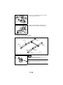
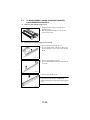
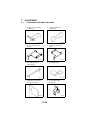
(10) Winding of the Scanner Drive Cable
Pulley F
Pulley E
Pulley D
Pulley C
Pulley B
4002D001AA
Pulley A
Front
Bead
1. Position the round bead of the Scanner Drive
Cable in the pulley as shown.
NOTE
Make sure that the bead snugly rests in the slit in the
pulley.
4002D002AA
D-36
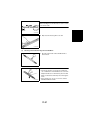
2. Wind the fixed bead end of the cable around the
pulley five turns clockwise, from the rear toward the
front side.
4002D003AA
3. Wind the hook end of the cable around the pulley
five turns counterclockwise, from the front toward
the rear side.
NOTE
Make sure that no part of the cable rides on the other.
4002D004AA
4. Slip the Cable Holding Jig onto the pulley to secure
the cable in position.
4002D501AA
Rear
Bead
5. Position the round bead of the Scanner Drive
Cable in the pulley as shown.
NOTE
Make sure that the bead snugly rests in the slit in the
pulley.
4002D005AA
6. Wind the fixed bead end of the cable around the
pulley five turns clockwise, from the front toward
the rear side.
4002D006AA
D-37
7. Wind the hook end of the cable around the pulley
five turns counterclockwise, from the rear toward
the front side.
NOTE
Make sure that no part of the cable rides on the other.
4002D007AA
8. Slip the Cable Holding Jig onto the pulley to secure
the cable in position.
4002D502AA
9. Mount the front and rear pulleys and bushings on
the shaft and install the shaft to the IR Unit.
10. Mount the Scanner Drive Gear on the shaft and
secure it in position with one screw.
4002D115AD
11. Install an Allen wrench into the holes in the shaft
and the IR Base Plate.
4002D116AD
12. Slide the front pulley and bushing to the front and
install one mounting screw.
4002D117AC
D-38
13. Slide the rear pulley and bushing to the rear and
secure install one mounting screw.
4002D118AD
Front
Pulley C
14. Wind the bead end of the cable around pulley C
and pulley B, then hook the bead onto the Adjustable Anchor.
Pulley B
4002D008AA
15. Wind the hook end of the cable around pulley A
and pulley B.
Pulley B
Pulley A
4002D009AA
16. Fit the hook end of the cable into the groove in the
Cable Guide and hook the spring.
Cable Guide
4002D119AB
Pulley F
Rear
17. Wind the bead end of the cable around pulley F
and pulley E, then hook the bead onto the Adjustable Anchor.
Pulley E
4002D010AA
D-39
18. Wind the hook end of the cable around pulley D
and pulley E.
Pulley E
Pulley D
4002D011AA
19. Fit the hook end of the cable into the groove in the
Cable Guide and hook the spring.
Cable Guide
4002D120AB
20. Mount the Scanner Motor Mounting Bracket Assy.
21. Remove the Cable Holding Jigs from the front and rear pulleys.
22. Remove the Allen wrench.
23. Mount the Scanner.
24. Reinstall the Left Cover, Right Cover, Rear Upper Cover and Control Panel.
25. Reinstall the Original Glass and EDH Glass.
26. Adjust the position of the Scanner and 2nd/3rd Mirrors Carriage.
☞ D-107
NOTE
Whenever the Scanner Drive Cables have been removed, be sure to carry out the following
check and adjustment: Orig. Size Adjust and Registration (CD).
D-40
2-6.
(1)
DEVELOPING UNIT
Remove of the Developing Unit
1. Swing down the Front Door and slide out the
Developing Unit.
2. Move the PC Drum Charge Corona to the rear,
raise it, and take it off.
4002U015AA
3. Loosen the two screws of the PC Drum stopper
and remove the PC Drum stopper.
4. Remove the PC Drum.
4002D122AB
4002D123AB
NOTES
• When reinstalling the PC Drum, refer to the illustration on the left and make sure of the correct direction
of installation. Be also sure to hold the PC Drum on
both sides with care not to touch the surface of the
drum with bare hands.
• When the PC Drum has been replaced, clear the
counts of “PC Drum 1”, “PC Drum 2” and “PC Drum
3” of “PM” of “Counter” available from the Tech. Rep.
mode.
5. Remove two screws and the Developing Unit Front
Cover.
4002D124AB
D-41
6. Remove two screws and the Stopper and Developer Scattering Prevention Plate.
4002D125AB
7. Remove two screws and the Cleaning Blade.
4002D127AB
NOTE
When reinstalling the Cleaning Blade, press the blade
tightly up against the mounting bracket.
1136D173AA
8. Remove two screws, unplug one connector, and
remove the ATDC Sensor.
4002D246AA
9. Unplug one connector.
10. Remove three screws and the PC Drum Paper Finger Holder Assy.
1156D061AA
D-42
Coupling Holder
NOTE
When reinstalling the PC Drum Paper Separator Finger Holder Assy., fit the collar of the assy onto the coupling holder in the rear.
Collar
1134D047AA
11. Remove the PC Drum Paper Fingers and AIDC Sensor Board as shown below.
Assy
AIDC Sensor Board
4002D128AB
NOTES
• At removal and reinstallation, use care not to damage the tip of the fingers.
Also, use care not to get hurt by the tip of the fingers.
• After reinstallation, perform the following adjustment procedure: Positioning of the PC
Drum Paper Separator Fingers.
☞ D-76
PC Drum Paper Separator Finger Installed
Top View
Rear View
1156D063AA
D-43
Hook the spring property.
After installation, check that the
Paper Separator Fingers operate
smoothly.
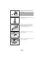
(2)
Cleaning of the Developer Scattering Prevention Plate
1. Using a brush, whisk dust off the Developer Scattering Prevention Plate.
4002D129AA
(3)
Cleaning of the DS Positioning Collars
1. Using a brush or a soft cloth dampened with alcohol, clean the DS Positioning Collars.
1136D177AA
(4)
Cleaning of the Toner Antispill Trap
1. Using a brush or a soft cloth, clean the Toner Antispill Trap.
4002D130AA
(5)
Replacement of the Cleaning Blade
1. Remove two screws and the Cleaning Blade, and
replace the Cleaning Blade with a new one.
4002D127AB
D-44
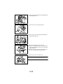
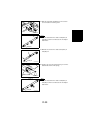
2. Remove the Toner Bottle from Main Hopper. Insert
a brush through the toner port and into the toner.
4002U022AA
3. Apply toner to the entire surface of the new Cleaning Blade.
4002D132AA
4. Using the brush, apply lubricant shipped with the
Cleaning Blade to the two side seals shown.
4002D133AB
5. Install the PC Drum.
4002D123AB
6. Fit the PC Drum stopper and tighten the screws.
4002D135AC
D-45
7. Apply a thin coat of toner to the surface of the PC
Drum.
4002U023AB
8. Holding onto the both sides of the PC Drum with
hands, turn the PC Drum a half turn in the direction
of the arrow.
4002U024AC
9. Holding onto the both sides of the PC Drum with
hands, turn the PC Drum a half turn in the direction
of the arrow.
4002U025AC
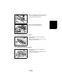
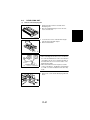
(6)
Replacement of the Developer
1. Remove the Sub Hopper Unit.
2. Dump the developer out the Developing Unit.
4002D126AA
D-46
3. Turning the Bucket Roller, pour fresh developer
evenly into the chamber.
1134D051AA
(7)
NOTES
• Shake the packet of developer well before opening
it.
• When the developer has been replaced, clear the
counts of “Developer 1” and “Developer 2” of “PM” of
“Counter” available from the Tech. Rep. mode and
run the F8 ATDC Sensor operation.
☞ D-81
Cleaning of the AIDC Sensor Board
1. Remove the PC Drum.
2. Using a brush or a soft cloth dampened with alcohol, clean the AIDC Sensor Board.
4002D136AA
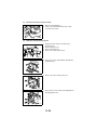
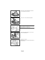
(8)
Cleaning of the PC Drum Paper Separator Fingers
1. Remove the PC Drum.
2. Using a brush or a soft cloth dampened with alcohol, clean the PC Drum Paper Separator Fingers.
4002D137AA
(9)
NOTE
During the cleaning procedure, use care not to
scratch, bend, or otherwise damage the tips of the PC
Drum Paper Separator Fingers. Be also careful not to
get hurt with the tips.
Removal of the Toner Antispill Seal
1. Remove the PC Drum Paper Separator Fingers
Assy.
2. Remove two screws and the Toner Antispill Plate
and Toner Antispill Seal.
4002D138AB
D-47
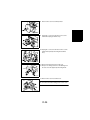
NOTE
When reinstalling the Toner Antispill Plate and Toner
Antispill Seal, press them in the direction of the arrows.
4002D139AB
(10) Cleaning of the Toner Antispill Seal
1. Remove the Toner Antispill Seal.
2. Using a brush, clean the Toner Antispill Seal.
4002D140AA
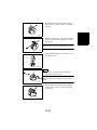
(11) Removal of the Main Erase Lamp
1. Swing down the Front Door.
2. Unplug one connector.
3. Remove one screw and the Main Erase Lamp.
4002D141AB
(12) Cleaning of the Main Erase Lamp Filter
1. Swing down the Front Door.
2. Remove the Main Erase Lamp Filter.
4002D142AB
D-48
3. Using a soft cloth dampened with alcohol, wipe
clean the Main Erase Lamp Filter.
1136D187AA
(13) Removal of the Ozone Filter (PC Drum Charge Corona)
1. Swing down the Front Door.
2. Swing out the Main Hopper.
3. Slide out the Ozone Filter.
4002D143AB
(14) Removal of the Ozone Filter (Image Transfer/Paper Separator Coronas)
1. Unhook one tab and remove the Filter Cover.
2. Pull out the Ozone Filter.
4002D144AB
(15) Removal of the Toner Collecting Bottle
1. Slide out the drawers from the applicable paper
source option.
(There is no need of sliding out the drawer for
LCC.)
2. Swing down the Toner Collecting Bottle Cover.
3. Remove the Toner Collecting Bottle.
4640U006AA
NOTE
When the Toner Collecting Bottle has been replaced,
clear the “Waste Toner-Count” count of “Consumables”
available from “Counter” under the Tech. Rep. mode.
D-49
2-7.
PC DRUM CHARGE CORONA AND IMAGE TRANSFER/
PAPER SEPARATOR CORONAS
(1)
Removal of the PC Drum Charge Corona
1. Swing down the Front Door and slide out the
Developing Unit.
2. Move the PC Drum Charge Corona to the rear,
raise it, and take it off.
4002U015AA
(2)
Cleaning of the PC Drum Charge Corona Housing
1. Remove the PC Drum Charge Corona.
2. Press the Mesh Holder on the front of the Corona
Unit in the direction of arrow A to remove the Grid
Mesh.
1156D070AA
3. Remove the Cleaning Pad Holder.
4. Remove the End Caps from the front and rear ends
of the Unit.
4002D146AB
5. Remove the Comb Electrode.
NOTES
• Use care not to deform the Comb Electrode.
• When removing the electrode, first snap off its spring
end.
1139D176AA
D-50
NOTE
When handling the Comb Electrode, be sure to hold it
onto its both ends.
10 mm
17 mm
4002D147AB
6. Wipe clean the Housing with a soft cloth.
1139D177AA
(3)
Cleaning of the PC Drum Charge Corona Grid Mesh
1. Blow all foreign matter off the Grid Mesh with a
blower brush.
1136D195AA
1136D196AA
NOTES
• If the blower brush is not effective in cleaning serious contamination of the Grid Mesh, use a soft cloth
dampened with alcohol. At this time, place the Grid
Mesh on a flat surface and sweep the cloth along the
mesh.
• After cleaning, use care not to touch the cleaned
Grid Mesh with bare hands.
D-51
(4)
Cleaning of the Comb Electrode
1. Clean Comb Electrode using the PC Drum Charge
Corona Cleaning Lever.
1156D072AA
(5)
Removal of the Image Transfer/Paper Separator Coronas
1. Swing down the Front Door.
2. Pull out the Transfer/Paper Separator Coronas.
1134D062AA
(6)
Cleaning of the Image Transfer Corona Wire
1. Swing down the Front Door.
2. Clean Image Transfer Corona Wire using the
Image Transfer Corona Wire Cleaning Lever.
1136D198AA
NOTE
If the Image Transfer Corona Wire is seriously contaminated, dampen a soft cloth with alcohol, hold it with a
pair of tweezers, and wipe the wire gently in one direction-from the hook end to the spring end.
4002D148AA
D-52
(7)
Removal of the Image Transfer Corona Wire
1. Remove the End Caps from the front and rear ends
of the Unit.
4002D149AA
2. Remove the corona wire, first at the spring end.
4002D150AA
(8)
Cleaning of the Paper Separator Corona Wire
1. Remove the four Paper Guides.
4002D151AA
2. Dampen a soft cloth with alcohol, hold it with a pair
of tweezers, and wipe the Paper Separator Corona
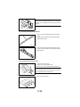
Wire gently in one direction.
NOTE
Wipe the wire from the hook to spring end.
1136D203AA
D-53
(9)
Removal of the Paper Separator Corona Wire
1. Remove the End Caps from the front and rear ends
of the Unit.
4002D149AA
2. Remove the four Paper Guides.
4002D151AA
3. Remove the corona wire, first at the spring end.
4002D150AA
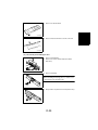
(10) Cleaning of the Image Transfer/Paper Separator Coronas Housing
1. Remove the four Paper Guides.
2. Remove the End Caps from the front and rear ends
of the Unit.
3. Remove the corona wire, first at the spring end.
4. Wipe clean the Housing with a soft cloth.
1136D205AA
D-54
(11) Cleaning of the Pre-Image Transfer Guide Plate
1. Using a soft cloth dampened with alcohol, wipe
clean the Pre-Image Transfer Guide Plate.
4002D152AA
D-55
2-8.
(1)
FUSING UNIT
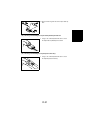
Disassembly of the Fusing Unit
1. Slide out the Fusing Unit.
2. Remove two screws and the Fusing Unit Front
Cover.
4002D153AB
NOTE
When reinstalling the Front Cover, hook the tab into
position.
4002D266AA
3. Remove four harness holders.
4. Unplug the connector of the Heater Lamp on the
front.
5. Remove the Heater Lamp cord from the one edge
cover.
4002D154AC
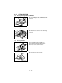
6. Remove five harness holders.
7. Remove one screw and the Heater Lamp cord.
4002D155AB
8. Remove one screw each and the upper and lower
lamp holders at the front.
4002D156AB
D-56
9. Remove four harness holders.
10. Remove the Upper Fusing Roller Heater Lamp harness from one wiring saddle.
11. Unplug two connectors of the Heater Lamp on the
rear.
12. Remove the Upper and Lower Fusing Roller
Heater Lamp harnesses from three edge covers.
4002D157AB
13. From the front side, slide out the Upper and Lower
Fusing Roller Heater Lamps.
4002D158AB
14. Unplug one Thermistor connector.
15. Remove the Thermistor harness from the harness
guide.
16. Remove one screw and the cord.
4002D159AD
17. Remove two screws and the Harness Guide.
4002D160AB
18. Remove two screws and the Upper Cover.
4002D161AA
D-57
19. Remove two screws and the Web Roller Assy.
4002D162AD
20. Remove two springs.
21. Remove one shoulder screw and the Lower Exit
Guide Assy.
4002D165AA
NOTE
When reinstalling the Upper Fusing Guide Plate Assy,
press both ends of the guide plate up against the
frame.
4002D164AB
22. Remove two screws and the Upper Fusing Guide
Plate Assy.
4002D163AA
23. Loosen the front roller pressure screw and unhook
the upper end of the spring.
NOTE
Repeat the same step for the spring in the rear.
4002D166AC
D-58
NOTE
When tightening the roller pressure screws with the
springs installed, tighten the front and rear ones alternately until there is no clearance in the mounting
bracket.
4002D167AB
24. Remove two screws and the rear holder.
4002D168AA
25. Remove two screws and the front holder.
4002D169AA
26. Remove two screws and the bracket.
4002D170AB
NOTE
When installing the mounting bracket, press its both
ends up against the frame.
4002D171AB
D-59
27. Remove one shoulder screw and the Pre-Fusing
Guide Plate.
28. Remove two springs.
4002D172AA
NOTE
When reinstalling the Pre-Fusing Guide Plate, make
sure that the rear harness is on the inside of the shoulder screw.
4002D173AA
29. Remove one E-ring, two shoulder screws, and two
gears.
4002D174AC
30. Remove two bearings.
31. Remove the bushing and Upper Fusing Roller.
4002D175AB
32. Remove the bearing and Lower Fusing Roller.
4002D176AB
D-60
(2)
Removal of the Upper Fusing Paper Separator Fingers
1. Remove the Upper Fusing Guide Plate Assy.
2. Remove five springs.
3. Slide out the shaft to remove five Upper Fusing
Paper Separator Fingers.
4002D177AA
(3)
Cleaning of the Upper Fusing Paper Separator Fingers
1. Remove the Upper Fusing Guide Plate Assy.
2. Using a soft cloth dampened with oil, wipe the five
Upper Fusing Paper Separator Fingers clean of
dirt.
4002D178AA
(4)
Cleaning of the Lower Fusing Paper Separator Fingers
1. Remove the Fusing Unit Front Cover.
2. Swing open the Lower Fusing Guide Plate Assy.
Using a soft cloth dampened with oil, wipe the five
Lower Fusing Paper Separator Fingers clean of
dirt.
4002D179AA
(5)
Cleaning of the Entrance Guide Plate
1. Using a soft cloth dampened with alcohol, wipe
clean the Entrance Guide Plate.
4002D180AA
D-61
(6)
Removal of the Upper Fusing Roller Thermistor
1. Slide out the Fusing Unit.
2. Unplug one connector.
3. Remove one screw and the Upper Fusing Roller
Thermistor Assy.
4002D159AD
4. Remove one screw and the Upper Fusing Roller
Thermistor.
4002D182AB
(7)
Cleaning of the Upper Fusing Roller Thermistor
1. Remove the Upper Fusing Roller Thermistor Assy.
2. Using a soft cloth dampened with oil, wipe the
Upper Fusing Roller Thermistor clean of dirt.
4002D183AA
(8)
Removal of the Lower Fusing Roller Thermistor
1.
2.
3.
4.
Slide out the Fusing Unit.
Remove the Fusing Unit Front Cover.
Remove the Pre-Fusing Guide Plate.
Remove one screw to free the Lower Fusing Roller
Thermistor Assy.
4002D184AB
D-62
5. Remove the rubber stopper, and slide out the shaft.
6. Remove the Lower Fusing Roller Thermistor.
4002D185AB
(9)
Cleaning of the Lower Fusing Roller Thermistor
1. Remove the Lower Fusing Roller Thermistor Assy.
2. Using a soft cloth dampened with oil, wipe the
Lower Fusing Roller Thermistor clean of dirt.
4002D186AA
(10) Removal of the Upper Fusing Roller Thermostat
1. Remove the Harness Guide.
2. Remove two screws and the Upper Fusing Roller
Thermostat Assy.
3. Remove two screws and the Upper Fusing Roller
Thermostat.
4002D187AA
(11) Cleaning of the Upper Fusing Roller Thermostat
1. Remove the Upper Fusing Roller Thermostat Assy.
2. Using a soft cloth dampened with silicone oil, wipe
the Upper Fusing Roller Thermostat clean of dirt.
4002D188AA
D-63
(12) Removal of the Web Roller
1. Remove the Web Roller Assy.
2. Remove two screws and the Web Roller bushing
and Web Take-Up Roller bushing.
NOTE
When reinstalling the Web Roller bushing and Web
Take-Up Roller bushing, ensure that they are in correct
position without being tilted or out of position.
4002D189AA
3. Remove the Web Roller and Web Take-Up Roller.
4002D190AB
NOTES
• When reinstalling the Web Roller and Web Take-Up
Roller, wind the web around the Web Take-Up Roller
at least one complete turn. Make also sure that the
web is not slack off.
• When the Web Roller has been removed, clear
Web-Count of Consumables Counter available from
Tech. Rep. mode.
(13) Removal of the Web Pressure Roller
1. Remove the Web Roller Assy.
2. Remove the Web Roller and Web Take-Up Roller.
3. Remove the springs at the front and rear.
4002D191AB
4. Remove the E-rings and bushings from the front
and rear end and remove the Web Pressure Roller.
4002D192AC
D-64
(14) Removal of the Misfeed Removal Knob Bushing
1. Slide out the Fusing Unit.
2. Remove one E-ring and the gear and bearing.
4002D193AC
3. Remove the Misfeed Removal Knob Assy. and
bushing.
4002D194AB
(15) Removal of the Fusing Unit Drive Coupling Gear
1. Slide out the Fusing Unit.
2. Remove one E-ring and the Fusing Unit Drive Coupling Gear.
4002D248AC
2-9.
(1)
TURNOVER UNIT
Cleaning of the Turnover Roller, Transport Rollers
1. Open the Lower Left Door.
2. Using a soft cloth dampened with alcohol, wipe
clean the Turnover Roller, Transport Rollers.
4002D195AC
D-65
3.
3-1.
ADJUSTMENT
ADJUSTMENT JIGS AND TOOLS USED
1. Front Door Interlock Switch
Actuating Jig
2. Predrive Inhibit Switch
Actuating Jig
1136D001AA
1136D005AA
3. Scanner Positioning Jig
(Front)
4. Scanner Positioning Jig
(Rear)
4002D505AA
4002D504AA
5. Sleeve/Magnet Roller
Positioning Jig
6. D.B. Adjusting Jigs
1136D003AA
1074D129AA
7. PC Drum Paper Separator
Finger Positioning Jig
8. Scanner Drive Cable
Holding Jig
1136D004AA
4002D503AA
D-66
3-2.
ADJUSTMENT REQUIREMENTS LIST
Adjustment Item
Requirements
Ref. Page
Automatically adjusted
☞ D-79
F5 AIDC Sensor
→ → →
☞ D-80
Registration (CD)
5.0 ± 0.5 mm
☞ D-83
Registration (FD)
Lead Edge Erase
Touch Panel Adj.
Orig. Size Adjust
F8 ATDC Sensor
☞ D-81
☞ D-82
→
☞ D-85
3.0 ± 1.0 mm
☞ D-87
Trail Edge Erase
→
☞ D-89
Loop Adjustment
Approx. 4.0 mm
☞ D-91
3.0 mm
☞ D-93
Erasure Width
Zoom (CD)
200 ± 1.0 mm
☞ D-95
Zoom (FD)
300 ± 1.0 mm
☞ D-97
Scale (CD)
☞ D-99
Scale (FD)
☞ D-101
D-67
3-3.
(1)
ADJUSTMENT OF SWITCHES
Microswitches
The following microswitches are used in various parts of this copier.
Blue (NC)
Yellow (NO)
Red (COM)
Red (COM)
1136D007AA
1136D008AA
Wiring for the NO Type
Wiring for the NC Type
NC (Normally-Closed)
: Current flows between NC and COM when the actuator is
open.
NO (Normally-Open)
: Current flows between NC and COM when the actuator is
closed.
COM (Common)
: Common contact for NC and NO.
Requirement
Actuator
COM
0.1 mm to
0.5 mm
The gap between the switch and actuator should be
0.1 to 0.5 mm when the actuator is closed.
NC
NO
1074D040AA
Out-of-Adjustment (When the actuator is closed)
• If the gap between the switch and actuator is too big, current does not at times flow to NC
or NO.
• If there is no gap between the switch and actuator, the actuator is bent or the switch can
be broken.
D-68
(2)
Adjustment of Front Door Interlock Switch
1.
2.
3.
4.
Swing down the Front Door.
Remove the Left Cover.
Slide out the Fusing Unit.
Remove four screws and the Cover.
NOTE
Do not remove the belt mounting screw on the cover.
4002D196AC
5. Loosen two screws that secure Front Door Interlock Switch.
4002D197AB
6. If the interlock switch is OFF when the Front Door
is closed in position, move the interlock switch
toward the front.
7. If it is impossible to close the Front Door in position
because of the interlock switch located excessively
to the front, move the switch to the rear.
4002D198AC
8. After the Interlock Switch is moved, tighten two
mounting screws.
9. Check the Interlock Switch ON/OFF by closing and
opening the Front Door.
Reference
An NO type switch is used for the Interlock Switch.
4002D199AB
D-69
3-4.
ADJUSTMENT OF BELT TENSION
Checks after Adjustment
• Turn the Timing Belt and check that all the Pulleys and grooves of the Belt fit securely.
• Each Belt should flex a little when the Belt is lightly pressed with a finger.
Reference
Since a given tension is applied by a tension spring to the Tension Lever that maintains the
tension of each timing belt, adjustment is completed by re-tightening the mounting screw
after it has been loosened.
(1)
Adjustment of the Suction Drive Timing Belt
1. Remove the Rear Cover.
2. Loosen the screw by which the Tension Lever is
mounted as shown on the left and then re-tighten
it.
4002D200AB
(2)
Adjustment of the Developing Unit Drive Timing Belt
1. Remove the Rear Cover.
2. Remove the Master Board mounting bracket Assy.
and FlyWheel.
3. Remove five screws and the Developing Unit Drive
Assy.
4002D072AB
Tension Lever 2
Tension
Lever 1
4. Remove two screws and the Tension Lever 2.
5. Loosen the screw by which the Tension Lever 1 is
mounted as shown on the left and then re-tighten
it.
6. Reinstall the Tension Lever 2.
4002D201AC
D-70
Tension Lever 2
7. Loosen two screws by which the Tension Lever 2 is
mounted as shown on the left and then re-tighten
it.
4002D202AC
(3)
Adjustment of the Scanner Motor Timing Belt
1. Remove the Rear Upper Cover.
2. Loosen three screws on the Scanner Motor mounting bracket and then re-tighten them.
4002D203AB
D-71
3-5.
(1)
SOLENOID POSITION ADJUSTMENT
Adjustment of Manual Feed Paper Pick-Up Solenoid
Requirement
The Paper Stoppers should be fixed perpendicularly when the Pick-Up Solenoid is ON.
Adjustment Procedure
1. Remove the Right Cover.
2. Remove five screws and the Manual Feed Paper
Pick-Up Solenoid mounting bracket Assy.
4002D090AB
3. Remove two screws and the bracket.
4002D206AB
4. Set the Pick-Up Solenoid to ON.
Reference
Since a keeper solenoid is used as the Pick-Up Solenoid, the set condition is kept when the Pick-Up Solenoid is on.
4002D207AA
D-72
5. Move the Pick-Up Solenoid in the direction of arrow ➀, then slowly move it in the direction of arrow ➁.
6. Move the Pick-Up Solenoid up to the position where the Lock Lever of the Paper Stopper becomes perpendicular (the position where the Paper Stopper is locked).
NOTES
• Be careful that the Pick-Up Solenoid is canceled from its set condition if moved excessively.
• If the set condition is canceled, set the solenoid to the energized (ON) position again and
repeat steps starting with step 6.
4002D208AA
4002D209AA
7. After the adjustment has been made, tighten the two the Pick-Up Solenoid mounting
screws.
Check after Adjustment
Check that the Paper Stopper is securely locked perpendicularly when the Pick-Up Solenoid is ON.
D-73
(2)
Adjustment of Turnover Roller Retraction Solenoid
Requirement
The gap between the E-ring of the plunger and the Retraction Solenoid should be 3 ± 0.2
mm when the Retraction Solenoid OFF.
Adjustment Procedure
1. Slide out the Fusing Unit.
2. Loosen two screws by which the Retraction Solenoid is mounted.
4002D210AC
3. Move the Retraction Solenoid so that the gap between the E-ring of the plunger and the
Solenoid is 3 ± 0.2 mm when the Retraction Solenoid OFF.
3 ± 0.2 mm
4002D012AA
4. After adjustment is completed, tighten the two Retraction Solenoid mounting screws.
D-74
(3)
Adjustment of Exit/Duplex Switching Solenoid
Requirement
The gap between the E-ring of the plunger and the Switching Solenoid should be 3 ± 0.2
mm when the Switching Solenoid OFF.
Adjustment Procedure
1.
2.
3.
4.
Remove the Left Cover.
Slide out the Fusing Unit.
Remove the Left Inner Cover.
Loosen two screws by which the Switching Solenoid is mounted.
4002D211AB
5. Move the Switching Solenoid so that the gap between the E-ring of the plunger and the
Solenoid is 3 ± 0.2 mm when the Switching Solenoid OFF.
3 ± 0.2 mm
4002D013AA
6. After adjustment is completed, tighten the two Switching Solenoid mounting screws.
D-75
(4)
Positioning of the PC Drum Paper Separator Fingers
(Separator Finger Solenoid)
Requirement
The gap between the three PC Drum Paper Separator Fingers and the PC Drum should be
0.3 to 1.0 mm when the Separator Finger Solenoid OFF.
NOTE
Use care not to deform the Separator Fingers during the adjustment procedure.
Adjustment Procedure
1. Attach the PC Drum Paper Separator Finger Positioning Jig to the Developer Unit.
1136D053AA
2. With the Separator Finger Solenoid in the deenergized position, adjust the position of the three
Paper Separator Fingers using an Allen wrench.
4002D212AC
Adjustment Instructions
• With the solenoid in the deenergized position, the tip
of the finger should be at a point between A to B
end.
• With the solenoid energized, the tip of the finger
should touch C.
1136D055AA
NOTE
If the requirements are not met, loosen the hexagon
socket head screw, loosen the two screws indicated on
the left, reposition the solenoid, and make the adjustment once again.
4002D213AB
D-76
(5)
Adjustment of Turnover Route Switching Solenoid
Requirement
The gap between the E-ring of the plunger and the Switching Solenoid should be 3 ± 0.2
mm when the Switching Solenoid OFF.
Adjustment Procedure
1. Remove the Left Cover.
2. Loosen two screws by which the Switching Solenoid is mounted.
4002D214AC
3. Move the Switching Solenoid so that the gap between the E-ring of the plunger and the
Solenoid is 3 ± 0.2 mm when the Switching Solenoid OFF.
3 ± 0.2 mm
4002D014AA
4. After adjustment is completed, tighten the two Switching Solenoid mounting screws.
D-77
3-6.
(1)
ACCESSING THE TECH. REP. MODE AND ADJUST MODE
Accessing the Tech. Rep. Mode
1. Press the Utility key.
2. Touch [Meter Count].
3. Press the following keys in this order:
Stop → 0 → 0 → Stop → 0 → 1
(2)
Accessing the Adjust Mode
1. Enter the Tech. Rep. mode.
2. Press the following keys in this order:
Start → Stop
D-78
3-7.
(1)
ELECTRICAL/IMAGE ADJUSTMENT
Touch Panel Adj.
Make this adjustment after either of the following procedures have been performed:
• Memory Clear
• Control Panel replacement
Adjustment Procedure
1. Call the Tech. Rep. mode to the screen.
2. Touch [Tech. Rep. Choice] and [System Set], in that order.
3. Touch [Touch Panel Adj.].
4. With the tip of a pen or similar object, touch the
four crosses (+) on the screen in sequence.
NOTES
• These crosses may be touched in any order; but be
sure to touch the center of each cross.
• Use care not to damage the screen surface with the
tip of the pen.
1155D191CA
5. The cross touched changes into a grid marker (that
consists of a square with a cross superimposed).
6. Touch [END].
1155D192CA
D-79
(2)
Orig. Size Adjust
Make this adjustment after any of the following procedures have been performed:
• Memory Clear
• The original size is incorrectly detected
• Replacement of the CCD Unit and Scanner parts
• An Original Size Detecting Sensor has been replaced or added
Adjustment Procedure
1. Place a blank sheet of A3 or 11 × 17 paper on the
Original Glass and lower the Original Cover.
4002D215AB
2.
3.
4.
5.
6.
Call the Tech. Rep. mode to the screen.
Touch [I.R. & EDH Check].
Touch [Function (I.R.)].
Touch [Orig. Size Adjust].
Press the Start Key to execute Orig. Size Adjust.
NOTE
The Start key remains lit up orange while this function is being run and lights up green as
soon as the sequence is completed.
7. If the adjustment results have been made okay, touch [Save].
NOTE
If the adjustment results have been NG, refer to “I/O Check List” of TROUBLESHOOTING.
D-80
(3)
F8 ATDC Sensor
Make this adjustment after any of the following procedures have been performed:
• Developer replacement
• ATDC replacement
• Memory Clear
NOTE
Make this adjustment before running an F5 AIDC Sensor operation.
Adjustment Procedure
1. Load the Developing Unit with fresh developer.
2. Install the Developing Unit in the copier.
3. Close the Front Door.
NOTE
Do not open and close the Front Door until the F8
ATDC Sensor operation is completed after the Power
Switch has been turned ON.
1134D051AA
4.
5.
6.
7.
8.
9.
Turn the Power Switch ON.
Call the Tech. Rep. mode to the screen.
Touch [Function].
Touch [Printer].
Touch [F8 ATDC Sensor].
Press the Start Key to let the copier make the F8 ATDC Sensor. (It will run for about 4
minutes.)
NOTES
• Note that the press of the Start Key lets the ATDC Sensor Adjustment run automatically.
Run this function only after the developer has been changed, ATDC Sensor replaced.
• While the copier is in the adjustment cycle, the Start Key is lit up orange. The key turns
green as soon as the adjustment cycle is completed.
10. Call the Adjust mode to the screen.
11. Touch [Printer].
12. Touch [ATDC Control].
13. Write down the value for “Current” in the ATDC column on the Adjust Label.
D-81
(4)
F5 AIDC Sensor
Make this adjustment after any of the following procedures have been performed:
• Developer replacement
• ATDC replacement
• Memory Clear
NOTE
This adjustment must be made after F8 ATDC Sensor.
Adjustment Procedure
1. Turn the Power Switch ON.
2. Call the Tech. Rep. mode to the screen.
3. Touch [Function].
4. Touch [Printer].
5. Touch [F5 AIDC Sensor].
6. Press the Start Key to let the copier make the F5 AIDC Sensor. (It will run for about 30
seconds.)
NOTE
While the copier is in the adjustment cycle, the Start Key is lit up orange. The key turns
green as soon as the adjustment cycle is completed.
D-82
(5)
Registration (CD)
Requirement
Width A on the test pattern output should fall within the
following range.
lead edge
1155D154AB
Specification
Adjust Mode
Setting Range
5.0 ± 0.5 mm
Registration (CD)
-8.2 to +8.2
This adjustment must be made after the PH Unit has been replaced.
Adjustment Procedure
1. Call the Adjust mode to the screen.
2. Touch [Printer].
3. Touch [Registration (CD)].
4. Select the paper source to be checked and adjusted.
5. Press the Start Key to let the copier produce a test pattern.
6. Check to see if width A on the test pattern is up to the specifications. If it is outside the
specified range, perform the following adjustment steps.
D-83
7. Press the Clear key to clear the current
setting value.
Use to clear the
setting value.
Use to enter the
setting value.
3
4
5
6
7
8
9
0
C
Use to change the
+ or - sign.
4002D510CB
8. Use the 10-key pad to change the setting
value.
NOTE
Use the Access key to select the sign of
+ or -.
Setting Value
4002D509CB
Setting Instructions
If width A is longer than the specifications, make the setting value smaller than the current
one.
If width A is shorter than the specifications, make the setting value greater than the current
one.
9. Press the Start key to let the copier produce a test pattern.
10. Check to see if width A on the test pattern is up to the specifications.
If it is outside the specified range, change the setting value and make a check again.
11. If width A falls within the specified range, touch [END] to validate the setting value.
D-84
(6)
Registration (FD)
Requirement
lead edge
Width A on the test pattern output should fall within the
following range.
1155D155AB
Specification
Adjust Mode
Setting Range
5.0 ± 0.5 mm
Registration (FD)
-8.2 to +8.2
This adjustment must be made after the PH Unit has been replaced.
Adjustment Procedure
1. Call the Adjust mode to the screen.
2. Touch [Printer].
3. Touch [Registration (FD)].
4. Press the Start Key to let the copier produce a test pattern.
5. Check to see if width A on the test pattern is up to the specifications. If it is outside the
specified range, perform the following adjustment steps.
D-85
6. Press the Clear key to clear the current
setting value.
Use to clear the
setting value.
Use to enter the
setting value.
3
4
5
6
7
8
9
0
C
Use to change the
+ or - sign.
4002D510CB
7. Use the 10-key pad to change the setting
value.
NOTE
Use the Access key to select the sign of
+ or -.
Setting Value
4002D511CB
Setting Instructions
If width A is longer than the specifications, make the setting value smaller than the current
one.
If width A is shorter than the specifications, make the setting value greater than the current
one.
8. Press the Start key to let the copier produce a test pattern.
9. Check to see if width A on the test pattern is up to the specifications.
If it is outside the specified range, change the setting value and make a check again.
10. If width A falls within the specified range, touch [END] to validate the setting value.
D-86
(7)
Lead Edge Erase
Requirement
Width A on the test pattern output should fall within the
following range.
NOTE
The measurement shall be taken at the center on the
leading edge of the paper.
1155D156AB
Specification
Adjust Mode
Setting Range
3.0 ± 1.0 mm
Lead Edge Erase
0 to 5
This adjustment must be made after the PH Unit has been replaced and following Registration (CD/FD).
Adjustment Procedure
1. Call the Adjust mode to the screen.
2. Touch [Printer].
3. Touch [Lead Edge Erase].
4. Press the Start Key to let the copier produce a test pattern.
5. Check to see if width A on the test pattern is up to the specifications. If it is outside the
specified range, perform the following adjustment steps.
D-87
6. Press the Clear key to clear the current
setting value.
Use to clear the
setting value.
Use to enter the
setting value.
3
4
5
6
7
8
9
0
C
4002D519AA
7. Use the 10-key pad to change the setting
value.
Setting Value
4002D512CB
Setting Instructions
If width A is longer than the specifications, make the setting value smaller than the current
one.
If width A is shorter than the specifications, make the setting value greater than the current
one.
8. Press the Start key to let the copier produce a test pattern.
9. Check to see if width A on the test pattern is up to the specifications.
If it is outside the specified range, change the setting value and make a check again.
10. If width A falls within the specified range, touch [END] to validate the setting value.
D-88
(8)
Trail Edge Erase
Requirement
Width A on the test pattern output should fall within the
following range.
NOTE
The measurement shall be taken at the center on the
trailing edge of the paper.
1155D157AB
Specification
Adjust Mode
Setting Range
3.0 ± 1.0 mm
Trail Edge Erase
0 to 5
This adjustment must be made after the PH Unit has been replaced and following Registration (CD/FD).
Adjustment Procedure
1. Call the Adjust mode to the screen.
2. Touch [Printer].
3. Touch [Trail Edge Erase].
4. Press the Start Key to let the copier produce a test pattern.
5. Check to see if width A on the test pattern is up to the specifications. If it is outside the
specified range, perform the following adjustment steps.
D-89
6. Press the Clear key to clear the current
setting value.
Use to clear the
setting value.
Use to enter the
setting value.
3
4
5
6
7
8
9
0
C
4002D519AA
7. Use the 10-key pad to change the setting
value.
Setting Value
4002D513CB
Setting Instructions
If width A is longer than the specifications, make the setting value smaller than the current
one.
If width A is shorter than the specifications, make the setting value greater than the current
one.
8. Press the Start key to let the copier produce a test pattern.
9. Check to see if width A on the test pattern is up to the specifications.
If it is outside the specified range, change the setting value and make a check again.
10. If width A falls within the specified range, touch [END] to validate the setting value.
D-90
(9)
Loop Adjustment
Requirement
Adjust so that a correct loop is formed at part A when paper is fed through.
Specification
Adjust Mode
Setting Range
Approx. 4.0 mm (visual)
Loop Adjustment
-3 to +3
This adjustment is to be made when any of the following symptoms occurs: variation in the
amount of print leading edge void, paper skew, folded edge, and misfeed.
Adjustment Procedure
1. Swing down the Front Door and fit the Front Door
Interlock Switch Actuating Jig.
4002D249AA
2. Remove three screws and the Cover.
NOTE
Do not remove the belt mounting screw on the cover.
4002D075AB
3. Press the Start Key to let the copier take up and feed a sheet of paper and visually
check that a correct loop is formed at part A of the location shown below.
4002D526AA
Advanced
The loop length is too long
causing the paper to have
too much slack.
4002D527AA
Correct
A good length of loop is
formed as the paper moves
into the Synchronizing Rollers.
D-91
4002D528AA
Retarded
No loop is formed causing
the paper to be taut.
If the loop length falls outside the specified range, perform the following adjustment steps.
4. Call the Adjust mode to the screen.
5. Touch [Printer].
6. Touch [Loop Adjustment].
7. Touch [Drawer].
8. Press the Clear key to clear the current
setting value.
Use to clear the
setting value.
Use to enter the
setting value.
3
4
5
6
7
8
9
0
C
Use to change the
+ or - sign.
4002D510CB
9. Use the 10-key pad to change the setting
value.
NOTE
Use the Access key to select the sign of
+ or -.
Setting Value
4002D514CB
Setting Instructions
If the loop length is longer than the specifications, decrease the setting value.
If the loop length is shorter than the specifications, increase the setting value.
10. Touch [END] to validate the setting value.
11. Go back to the Basic screen.
12. Press the Start key and check for the loop length again.
13. If the loop length falls outside the specified range, change the setting value and make a
check again.
14. Place a sheet of paper on the Multi Bypass Tray.
15. Following the same procedures, make the loop adjustment for the Multi Bypass Tray.
D-92
(10) Erasure Width
Requirement
Adjust so that no shade of the Original Scale is produced on the sample copy.
Adjust Mode
Setting Range
Erasure Width
0 to 5
This adjustment must be made when a shadow is produced from the Original Scale.
Adjustment Procedure
1. Call the Tech. Rep. mode to the screen.
2. Touch [I.R. (EDH) Check].
3. Touch [Tech. Rep. Choice].
4. Touch [Erasure Width].
5. Press the Clear key to clear the current
setting value.
Use to clear the
setting value.
Use to enter the
setting value.
1
2
3
4
5
6
7
8
9
0
C
4002D519AA
6. Using the 10-Key Pad, set “3” for Erasure
Width.
Setting Value
4002D533CA
7. Touch [END] to validate the setting value.
8. Go back to the Basic screen.
9. Set Lead Edge Erase to 0.
☞ D-87
NOTE
Be sure to record to current setting value.
10. Go back to the Basic screen.
D-93
4002D215AB
11. Place a sheet of A3 or 11 × 17 paper on the Original Glass and lower the Original Cover.
12. Make a copy in the full size (× 1.000) mode.
13. Check to see if a shadow of the Original Scale is
produced on the sample copy.
If no shadow is produced, return Lead Edge Erase
to the value which has been recorded.
If a shadow is produced, perform the following
adjustment steps.
14. Call the Tech. Rep. mode to the screen.
15. Touch [I.R. (EDH) Check].
16. Touch [Tech. Rep. Choice].
17. Touch [Erasure Width].
18. Press the Clear key to clear the current
setting value.
Use to clear the
setting value.
Use to enter the
setting value.
1
2
3
4
5
6
7
8
9
0
C
4002D519AA
19. Use the 10-key pad to change the setting
value.
Setting Value
4002D533CA
20. Touch [END] to validate the setting value.
21. Go back to the Basic screen.
22. Make another sample copy for rechecking.
If a shadow from the Original Scale is produced, try another setting value and check
again.
If no shadow is produced, return Lead Edge Erase to the value which has been
recorded.
D-94
(11) Zoom (CD)
Requirement
Adjust to eliminate any difference in width between the original test pattern and a test pattern copy.
Adjust Mode
Setting Range
Zoom (CD)
0.990 to 1.010
This adjustment must be made when the CCD Unit has been replaced.
Adjustment Procedure
1. Call the Tech. Rep. mode to the screen.
2. Touch [Function].
3. Touch [Printer].
4. Touch [F12 Test Pattern].
5. Touch [F12-3 (64-dot checkered)].
6. Select the paper source loaded with A4 crosswise or Letter crosswise paper.
7. Press the Start key, and without any delay, press the Stop key to let the copier produce
a test pattern.
8. Go back to the Basic screen.
9. Place the test pattern on the Original Glass and
lower the Original Cover.
10. Make a copy in the full size (× 1.000) mode.
lead edge
4002D269AA
A
11. Measure width A on the original test pattern and
the copy of the test pattern and find any difference
between the two measurements.
If there is any difference, perform the following
adjustment steps.
4002D531AA
D-95
12. Call the Adjust mode to the screen.
13. Touch [IR].
14. Touch [Zoom (CD)].
15. Press the Clear key to clear the current
setting value.
Use to clear the
setting value.
Use to enter the
setting value.
1
2
3
4
5
6
7
8
9
0
C
4002D519AA
16. Use the 10-key pad to change the setting
value.
Setting Value
4002D534CA
Setting Instructions
If width A on the test pattern copy is greater than that on the original test pattern, decrease
the setting value.
If width A on the test pattern copy is smaller than that on the original test pattern, increase
the setting value.
17. Touch [END] to validate the setting value.
18. Go back to the Basic screen.
19. Perform steps 9 and 10.
20. Check for any difference in width A between the original test pattern and the test pattern
copy.
If there is any difference, try another setting value for rechecking.
D-96
(12) Zoom (FD)
Requirement
Adjust to eliminate any difference in width between the original test pattern and a test pattern copy.
Adjust Mode
Setting Range
Zoom (FD)
0.990 to 1.010
This adjustment must be made when the Scanner Drive Cable has been replaced.
Adjustment Procedure
1. Call the Tech. Rep. mode to the screen.
2. Touch [Function].
3. Touch [Printer].
4. Touch [F12 Test Pattern].
5. Touch [F12-3 (64-dot checkered)].
6. Select the paper source loaded with A4 lengthwise or Letter lengthwise paper.
7. Press the Start key, and without any delay, press the Stop key to let the copier produce
a test pattern.
8. Go back to the Basic screen.
9. Place the test pattern on the Original Glass and
lower the Original Cover.
10. Make a copy in the full size (× 1.000) mode.
4002D217AD
11. Measure width A on the original test pattern and
the copy of the test pattern and find any difference
between the two measurements.
If there is any difference, perform the following
adjustment steps.
lead edge
A
4002D532AA
D-97
12. Call the Adjust mode to the screen.
13. Touch [IR].
14. Touch [Zoom (FD)].
15. Press the Clear key to clear the current
setting value.
Use to clear the
setting value.
Use to enter the
setting value.
1
2
3
4
5
6
7
8
9
0
C
4002D519AA
16. Use the 10-key pad to change the setting
value.
Setting Value
4002D535CA
Setting Instructions
If width A on the test pattern copy is greater than that on the original test pattern, decrease
the setting value.
If width A on the test pattern copy is smaller than that on the original test pattern, increase
the setting value.
17. Touch [END] to validate the setting value.
18. Go back to the Basic screen.
19. Perform steps 9 and 10.
20. Check for any difference in width A between the original test pattern and the test pattern
copy.
If there is any difference, try another setting value for rechecking.
D-98
(13) Scale (CD)
Requirement
Adjust so that the leading edge of the image of the scale on the copy sample meets the
requirements.
Adjust Mode
Setting Range
Scale (CD)
-10.0 to +10.0
This adjustment must be made when the CCD Unit or Original Glass has been replaced.
Adjustment Procedure
1. Place a scale on the Original Glass so that it runs
parallel with the Original Width Scale and its leading edge is aligned with the Original Length Scale.
4002D270AA
2. Set Registration (CD) to +8.2.
☞ D-83
3. Set Erasure Width to 0.
☞ D-93
NOTE
Be sure to record the current setting value.
4.
5.
6.
7.
Go back to the Basic screen.
Select the paper source that has been checked for “Registration (CD).”
Make a copy in the full size (× 1.000) mode.
Make a copy at an enlargement ratio (e.g.: × 1.294).
Scale Leading Edge Position
Full-Size Copy Enlarged Copy
4002D506AA
8. Check to see if the leading edge of the scale is
reproduced on the full-size copy.
9. Check to see if the position of the leading edge of
the scale reproduced on the enlarged copy does
not deviate from that on the full-size copy.
If the conditions of steps 8 and 9 are met, return
Registration (CD) and Erasure Width to the values
recorded.
If conditions of steps 8 and 9 are not met, perform
the following adjustment steps.
D-99
10. Call the Adjust mode to the screen.
11. Touch [IR].
12. Touch [Scale (CD)].
13. Press the Clear key to clear the current
setting value.
Use to clear the
setting value.
Use to enter the
setting value.
3
4
5
6
7
8
9
0
C
Use to change the
+ or - sign.
4002D510CB
14. Use the 10-key pad to change the setting
value.
NOTE
Use the Access key to select the sign of
+ or -.
Setting Value
4002D536CA
Setting Instructions
If the position of the leading edge of the scale reproduced on the enlarged copy deviates
from that on the full-size copy, decrease the setting value.
If the leading edge of the scale is not reproduced on the full-size copy, increase the setting
value.
15. Go back to the Basic screen.
16. Perform steps 5 through 9.
17. Check to see if conditions of steps 8 and 9 are met.
If the conditions are not met, try another setting value for rechecking.
18. If the conditions are met, return Registration (CD) and Erasure Width to the values
recorded.
D-100
(14) Scale (FD)
Requirement
Adjust so that the leading edge of the image of the scale on the copy sample meets the
requirements.
Adjust Mode
Setting Range
Scale (FD)
-7.0 to +7.0
This adjustment must be made when the Scanner has been removed the Scanner Drive
Cable or Original Glass has been replaced.
Adjustment Procedure
1. Place a scale on the Original Glass so that it runs
parallel with the Original Length Scale and its leading edge is aligned with the Original Width Scale.
4002D218AC
2. Set Lead Edge Erase to 0.
☞ D-87
3. Set Registration (FD) to +8.2.
☞ D-85
4. Set Erasure Width to 0.
☞ D-93
NOTE
Be sure to record the current setting value.
5. Go back to the Basic screen.
6. Make a copy in the full size (× 1.000) mode.
7. Make a copy at an enlargement ratio (e.g.: × 1.294).
Scale Leading Edge Position
Full-Size Copy Enlarged Copy
4002D507AA
8. Check to see if the leading edge of the scale is
reproduced on the full-size copy.
9. Check to see if the position of the leading edge of
the scale reproduced on the enlarged copy does
not deviate from that on the full-size copy.
If the conditions of steps 8 and 9 are met, return
Lead Edge Erase, Registration (FD), and Erasure
Width to the values recorded.
If conditions of steps 8 and 9 are not met, perform
the following adjustment steps.
D-101
10. Call the Adjust mode to the screen.
11. Touch [IR].
12. Touch [Scale (FD)].
13. Press the Clear key to clear the current
setting value.
Use to clear the
setting value.
Use to enter the
setting value.
3
4
5
6
7
8
9
0
C
Use to change the
+ or - sign.
4002D510CB
14. Use the 10-key pad to change the setting
value.
NOTE
Use the Access key to select the sign of
+ or -.
Setting Value
4002D537CA
Setting Instructions
If the position of the leading edge of the scale reproduced on the enlarged copy deviates
from that on the full-size copy, decrease the setting value.
If the leading edge of the scale is not reproduced on the full-size copy, increase the setting
value.
15. Go back to the Basic screen.
16. Perform steps 6 through 9.
17. Check to see if conditions of steps 8 and 9 are met.
If the conditions are not met, try another setting value for rechecking.
18. If the conditions are met, return Lead Edge Erase, Registration (FD), and Erasure
Width to the values recorded.
D-102
3-8.
(1)
OTHER ADJUSTMENTS
Adjustment of the Reference Position of Each Drawer
Requirement
lead edge
Width A on the test pattern output should fall within the
following range.
Specification
5 ± 0.5 mm
1155D154AB
The adjustment should be made after Registration (CD/FD).
Adjustment Procedure
1. Call the Adjust mode to the screen.
2. Touch [Printer].
3. Touch [Registration (CD)].
4. Select the paper source to be checked and adjusted.
5. Press the Start Key to let the copier produce a test pattern.
6. Check to see if width A on the test pattern is up to the specifications. If it is outside the
specified range, perform the following adjustment steps.
D-103
7. Slide out the drawer used as the paper source for
the test pattern and then loosen the seven screws
shown on the left.
4002D250AA
8. Watching the scale on the adjustment plate in the
drawer, move the Edge Guide.
4002D251AA
Setting Instructions
If width A on the test pattern is greater than the specifications, move the Edge Guide to the
rear.
If width A on the test pattern is smaller than the specifications, move the Edge Guide to the
front.
9. Press the Start key to let the copier produce a test pattern.
10. Check to see if width A on the test pattern is up to specifications.
If the width falls outside the specified range, move the Edge Guide as necessary and
check again.
11. Following the same procedures, make the adjustment for all drawers.
D-104
(2)
Adjustment of the Reference Position of the Multi Bypass Tray
Requirement
lead edge
Width A on the test pattern output should fall within the
following range.
Specification
5 ± 0.5 mm
1155D154AB
The adjustment should be made after Registration (CD/FD).
Adjustment Procedure
1. Place a sheet of paper on the Multi Bypass Tray.
2. Call the Adjust mode to the screen.
3. Touch [Printer].
4. Touch [Registration (CD)].
5. Touch [Manual].
6. Press the Start Key to let the copier produce a test pattern.
7. Check to see if width A on the test pattern is up to the specifications. If it is outside the
specified range, perform the following adjustment steps.
8. Loosen one screw that secures the Multi Bypass
Tray in position and move the tray as necessary.
4002D219AB
Setting Instructions
If width A on the test pattern is greater than the specifications, move the Multi Bypass Tray
to the rear.
If width A on the test pattern is smaller than the specifications, move the Multi Bypass Tray
to the front.
9. Press the Start key to let the copier produce a test pattern.
10. Check to see if width A on the test pattern is up to specifications.
If the width falls outside the specified range, move the tray as necessary and check
again.
D-105
(3)
Adjustment of the Upper Right Door (Multi Bypass Unit)
If the Right Door has been removed and reinstalled, the position of the actuator of Upper
Right Door Set Sensor may deviate from the correct position. Hence, the necessity of the
following adjustment.
1. Lifting the front end slightly, tighten the two mounting screws.
NOTE
At this time, only temporarily tighten these screws.
4002D220AB
2. Lightly close the Upper Right Door so that the Set
Sensor actuator will not contact the frame.
4002D221AA
3. Due to its own weight, the front end of the Upper
Right Door tends to hang lower. Lifting the front
end slighting the two mounting screws.
4002D222AB
4. Open and close the Upper Right Door two to three
times to make sure that the actuator of the Upper
Right Door Set Sensor does not contact the frame.
4002D223AA
D-106
(4)
Adjustment of the Position of the Scanner and 2nd/3rd Mirrors Carriage
Requirement
With the Scanner fixed to the Scanner Drive Cables, there should be no gap between the
Scanner/Mirrors Carriage Positioning Jig and the Scanner and also between the Scanner/
Mirrors Carriage Positioning Jig and the 2nd/3rd Mirror Carriage.
Make this adjustment after either of the following procedures have been performed:
• After the Scanner Drive Cable has been replaced.
• When the Scanner Fixing Bracket has been removed from Scanner Drive Cable.
• When the Scanner Drive Cable comes unwound.
Adjustment Procedure
1. Remove the Original Glass and Rear Upper Cover.
2. Move the Scanner so that the Scanner Positioning
Screw is aligned with the hole in the upper frame.
3. Insert a screwdriver into the hole in the upper
frame and loosen the Scanner Positioning Screw
(so that the Scanner Drive Cables and the Scanner
can be moved independently of each other).
4002D234AC
4. Install the Scanner Positioning Jigs between the
Scanner and the 2nd/3rd Mirrors Carriage Assy.
4002D252AC
NOTE
When installing the Scanner Positioning Jigs, be sure
to fit the tabs on the jigs into the holes at the front and
rear ends of the frame.
4002D253AB
D-107
4002D508AA
5. Press the Scanner and the 2nd/3rd Mirrors Carriage Assy tightly up against the Scanner Positioning Jigs.
6. Check that there is no clearance between the
Scanner and the Scanner Positioning Jig, and
between the 2nd/3rd Mirrors Carriage Assy and
the Scanner Positioning Jig.
If there is any clearance, adjust parallel alignment
of the 2nd/3rd Mirrors Carriage Assy after this
adjustment has been completed.
7. Tighten the two Scanner Positioning Screws.
4002D237AB
(5)
Adjustment of the 2nd/3rd Mirrors Carriage Assy for Parallel Alignment
1. Remove the Original Glass.
2. Loosen one screw that secures the adjusting plate.
4002D235AB
a
3. Turn the adjusting screw as necessary.
b
Adjusting Screw
4002D236AA
Setting Instructions
If there is a gap between the 2nd/3rd Mirrors Carriage Assy and the Scanner Positioning
Jig at the front, turn the adjusting screw clockwise.
If there is a gap between the 2nd/3rd Mirrors Carriage Assy and the Scanner Positioning
Jig in the rear, turn the adjusting screw counterclockwise.
4. Lightly press the 2nd/3rd Mirrors Carriage Assy up against the Scanner Positioning Jig
and check that there is no clearance between the two.
5. Tighten one screw to secure the adjusting plate in position.
D-108
(6)
Adjustment of the Gap Between the Doctor Blade and Sleeve Roller
(D.B. Adjustment)
Requirement
The gap between the Doctor Blade and Sleeve Roller should be 0.6 + 0.03 - 0.05 mm.
Adjustment Procedure
1. Slide out the Developer Unit and remove the PC
Drum Charge Corona and PC Drum.
2. Remove two screws and the Developer Scattering
Prevention Plate.
4002D224AA
3. Using a brush, whisk developer off the surface of
the Sleeve Roller.
4002D225AA
4. Install the Sleeve/Magnet Roller Positioning Jig into
the Developer Unit.
1136D051AA
5. Loosen three screws that secure the Doctor Blade.
Insert the D.B. Adjusting Jigs between the Doctor
Blade and Sleeve Roller.
6. Press down the Doctor Blade until it positively contacts the D.B. Adjusting Jigs. Then, tighten the
three screws to secure the Doctor Blade.
4002D226AA
D-109
4.
4-1.
MISCELLANEOUS
INSTALLATION OF THE KEY COUNTER SOCKET (OPTION)
1. Remove the Right Cover.
2. Remove the Counter Cover.
4002D227AA
3. Swing down the Front Door and slide out the
Developer Unit.
4. Remove three screws and the cover.
NOTE
Do not remove the belt mounting screw on the cover.
4002D075AB
5. Connect the Key Counter Socket connector.
6. Using one screw and nut, secure the counter
socket.
NOTE
When the Key Counter Socket is mounted, set to “ON”
the “Key Counter” available from the Security mode.
4002D228AB
D-110
4-2.
MOUNTING THE ORIGINAL SIZE DETECTING SENSORS
(OPTION)
NOTE
When an Original Size Detecting Sensor has been added, turn “ON” “Original Size Detecting Option” of “System Input” under the Tech. Rep. mode and make the “Orig. Size Adjustment.”
☞ D-80
1. Remove the Original Glass and EDH Glass.
2. Install the Original Size Detecting Sensor.
FD3 (✽2)
FD1 (✽1)
(✽3)
A
CD2 (✽2)
G
4002D268AB
✽ 1: Standard for the Except U.S.A., Canada
✽ 2: Standard for the Other Areas (Except Korea, Taiwan)
✽ 3: Mount the sensor in hole D for Korea and Taiwan.
Mount it in hole E for areas other than Korea and Taiwan.
D-111
4-3.
FLASH MEMORY
Software has conventionally been upgraded by replacing ROM on each board. This copier
employs flash memory for the system control IC mounted on the Master Board and Image
Processing Board. Its contents are reprogrammed easily by performing the following steps
using the IC card (memory card), into which data has been previously downloaded.
NOTES
• NEVER remove or insert the memory card with the copier power turned ON.
• An error code appears on the Touch Panel while data is being rewritten. It does not, however, indicate any problematic symptom and can be ignored.
(1)
Rewriting the Master Board Data
1. With the Power Switch in the OFF position, unplug the power cord from the power outlet.
2. Remove the Rear Cover.
3. Insert the memory card into the Master Board.
4002D229AC
LD5
LD3
LD6
LD7
LD4
4002D267AA
4. Plug the power cord into the power outlet.
5. Turn ON the Power Switch.
6. This starts the data rewriting sequence.
NOTE
While the data is being rewritten, LD3 on the Master
Board remains blinking and LD4 remains OFF.
7. Check that LD3 and LD4 on the Master Board turn
ON.
8. Unplug the power cord from the power outlet.
NOTE
Do not turn OFF the Power Switch at this time.
9. Remove the memory card.
4002D230AA
D-112
10. Turn OFF the Power Switch.
11. Plug the power cord into the power outlet.
12. Turn ON the Power Switch.
13. Call the Tech. Rep. Mode to the screen.
14. Touch [ROM Version].
15. Check to see if the printer version shown on the screen matches the version marked on
the flash memory.
(2)
Rewriting the Image Processing Board Data
1. With the Power Switch in the OFF position, unplug the power cord from the power outlet.
2. Remove the Right Cover.
3. Close the Front Cover.
4. Remove three screws and the PH Cooling Fan
Motor mounting bracket Assy.
NOTE
Do not disconnect the connector of the PH Cooling
Fan Motor.
5. Remove six screws and the mounting bracket.
4002D046AB
6. Insert the memory card into the Image Processing
Board.
4002D231AB
7. Plug the power cord into the power outlet.
8. Holding down the particular numeric key of the 10Key Pad corresponding to the language in which
the data is to be rewritten, turn ON the Power
Switch.
1154D277AA
NOTE
For the specific numeric key of the 10-Key Pad, refer to
the “List of Numeric Keys Corresponding to Languages.”
☞ D-114
9. The data rewriting sequence starts.
(The Start key starts blinking red.)
10. Check that a message appears on the Touch
Panel, indicating that the data has been rewritten
correctly.
(The Start key lights up green steadily.)
D-113
Check Items
• “Downloading Completed.” is shown.
• The number shown to the left of “Language”
matches that entered from the 10-Key Pad when the
Power Switch is turned ON.
• The Check Sum value matches the value given on
the memory card.
11. If rewriting has been NG (as indicated by the Start
key lighting up red), perform steps 12 and 13 and
then start the procedure over, beginning with step
5.
NOTE
If the second rewriting fails, perform steps 12 and 13
and abandon the procedure.
12. Unplug the power cord from the power outlet.
NOTE
At this time, do not turn OFF the Power Switch.
13. Remove the memory card.
4002D233AA
<List of Numeric Keys Corresponding to Languages>
10-Key Pad
Marketing
Areas
None pressed
U.S.A. and
Canada
2
3
4
Europe 2
Europe 3
Other
Areas 1
Other
Areas 2
English
English
English
English
English
English
French
German
Ukrainian
Czech
Spanish
Chinese 1
Spanish
French
Lithuanian
Slovak
Japanese
Languages
Europe 1
1
Portuguese Chinese 2
Dutch
Estonian
Turkish
French
Italian
Hungarian
French
Russian
Spanish
Romanian
German
Thai
Portuguese
Polish
Greek
Malay
Indonesian
Danish
Croatian
Chinese
Norwegian
German
Arabic
Arabic
Swedish
Russian
Slovenian
Japanese
Finnish
Chinese 1
Japanese
Chinese 2
D-114
Japanese
(3)
Rewriting the ECC Board Data (option)
1. Unplug the power cord from the power outlet with the Power Switch OFF.
2. Remove the Rear Cover.
3. Insert the memory card into the ECC Board.
4002D538AB
4. Plug the power cord into the power outlet.
5. Turn ON the Power Switch.
6. This starts the rewriting sequence.
NOTE
D1 on the Master Board remains blinking while data is
being rewritten.
4002D540AB
7. Check that D3 on the ECC Board turns ON.
8. If an LED other than D3 turns ON or if it takes
longer than 3 min. to rewrite the data, perform
steps 9 and 10, turn OFF the Power Switch, and
start the procedure over beginning with step 4.
9. Unplug the power cord from the power outlet.
NOTE
At this time, do not turn OFF the Power Switch.
10. Remove the memory card.
4002D539AB
D-115
(4)
Rewriting the Master Board, Image Processing Board, and ECC Board (Option)
Simultaneously
NOTE
Steps 4 and 9 are to be performed only when the ECC Board (option) is mounted.
1. With the Power Switch in the OFF position, unplug the power cord from the power outlet.
2. Insert the memory card into the Image Processing Board.
☞ D-113
3. Insert the memory card into the Master Board.
☞ D-112
4. Insert the memory card into the ECC Board.
☞ D-115
5. Plug the power cord into the power outlet.
6. Turn ON the Power Switch.
7. Check that a message appears on the Touch
Panel, indicating that the data has been rewritten
correctly.
4002D525AA
8. Check that LD3 and LD4 on the Master Board are
ON.
LD5
LD3
LD6
LD7
LD4
Check Items
• “Downloading Completed.” is shown.
• The number shown to the left of “Language”
matches that entered from the 10-Key Pad when the
Power Switch is turned ON.
• The Check Sum value matches the value given on
the memory card.
4002D267AA
9. Check that D3 on the ECC Board turns ON.
4002D540AB
10. Unplug the power cord from the power outlet.
NOTE
Do not turn OFF the Power Switch at this time.
11. Remove the memory card.
D-116
4-4.
REMOUNTING EPROM
NOTE
If the PW Board has replaced, be sure to remount EPROM from the old to new PW Board.
If the PW Board has been replaced and EPROM has not been remounted, be sure to
replace the PC Drum with a new one. EPROM contains no data in this case, so make
entries again of numeric values given on the Adjust Label.
(1)
Remounting EPROM on the Master Board
1. Remove the Master Board.
2. Remove EPROM (IC101) from the new Master Board.
3. Remove EPROM (IC101) from old Master Board and remount it onto the new Master
Board.
4002D529AA
A
NOTE
Note the alignment notch (A) on EPROM (IC101) when
mounting the IC.
4002D530AA
D-117
(2)
Remounting EPROM on the Image Processing Board
1. Remove the Image Processing Board.
2. Remove EPROM (IC400) from the new Image Processing Board.
3. Remove EPROM (IC400) from old Image Processing Board and remount it onto the
new Image Processing Board.
4002D254AB
A
NOTE
Note the alignment notch (A) on EPROM (IC400) when
mounting the IC.
4002D255AB
D-118
SWITCHES ON PWBs,
TECH. REP. SETTINGS
CONTENTS
1. CONTROL PANEL KEYS AND TOUCH PANEL ............................................. S-1
1-1. Control Panel Keys .................................................................................. S-1
1-2. Explanation of the Touch Panel ............................................................... S-3
(1) Basis Screen ................................................................................... S-3
(2) Warning Screens ............................................................................. S-4
2. FUNCTION OF SWITCHES AND OTHER PARTS ON PWBs ........................ S-5
2-1. PWB Location .......................................................................................... S-5
2-2. PWB-S (Tech. Rep. Setting Switches Board) .......................................... S-5
(1) Clearing Procedures ........................................................................ S-6
(2) Data/Conditions Cleared by Reset Switches/Pins ........................... S-6
3. UTILITY MODE ................................................................................................ S-7
3-1. Utility Mode selection Screen .................................................................. S-7
3-2. Utility Mode Function Tree ....................................................................... S-7
3-3. Settings in the Utility Mode ...................................................................... S-8
(1) User’s Choice Mode ........................................................................ S-8
(2) Administrator Mode ......................................................................... S-15
4. TECH. REP. MODE ......................................................................................... S-17
4-1. Tech. Rep. Mode Menu Screen ............................................................... S-17
4-2. Tech. Rep. Mode Function Setting Procedure ......................................... S-17
4-3. Tech. Rep. Mode Menu Function Tree .................................................... S-18
4-4. Setting in the Tech. Rep. Mode ............................................................... S-21
(1) Function ........................................................................................... S-21
(2) Tech. Rep. Choice ........................................................................... S-24
(3) System Input .................................................................................... S-26
(4) Counter ............................................................................................ S-27
(5) I/O Check ......................................................................................... S-32
(6) I.R. & EDH Check ............................................................................ S-32
(7) ROM Version ................................................................................... S-33
(8) RD Mode ......................................................................................... S-34
(9) Level History .................................................................................... S-36
(10) Admin. Mode ................................................................................... S-37
(11) Finisher ............................................................................................ S-37
5. SECURITY MODE ........................................................................................... S-38
5-1. Security Mode Menu Screen ................................................................... S-38
5-2. Security Mode Setting Procedure ............................................................ S-38
5-3. Settings in the Security Mode .................................................................. S-39
6. ADJUST MODE ............................................................................................... S-41
6-1. Adjust Mode Menu Screen ...................................................................... S-41
6-2. Adjust Mode Setting Procedure ............................................................... S-41
6-3. Adjust Mode Function Tree ...................................................................... S-42
6-4. Settings in the Adjust Mode ..................................................................... S-43
i
1.
1-1.
CONTROL PANEL KEYS AND TOUCH PANEL
Control Panel Keys
1 2 3 4
20
19
5
6
7
18
8
9
17
10
16
11
15
12
4002O279EA
14
13
S-1
1. HDD Lamp
• Lights up to indicate that the Hard Disk
Drive Kit (option) is being accessed.
2. Access Key
• Press to enter the access number when
Copy Track of the Administrator mode
available.
Press the access Key.
3. Energy Saver Key
• Press to set machine into the Energy
Saver mode.
4. Interrupt Key
• Press to select the Interrupt mode.
5. Panel Reset Key
• Press to set the machine into the initial
mode, clearing all settings made on the
control panel.
6. Clear Key
• Clear the various numeric values.
7. Stop Key
• Stop a print cycle.
• Stop a scanning cycle.
8. Start Key
• Start a print cycle.
9. Touch Panel
• Shows various screens and message.
10. Mode Check Key
• Press to show the Mode Check screen.
11. Original Key
• Press to select the Mixed Orig. Detection and other document-related functions setting screen.
12. Job List Key
• Press to check for the settings made for
a job (Mode Check), modify the settings
of a job (Change), delete a job (Delete),
and unlock a job (Unlock).
13. Ready Key
• Lights up to indicate that data can be
transferred.
14. On Line Key
• Press to select either Online or Offline
mode.
15. Display Contrast Knob
• Use to adjust the brightness of the
Touch Panel.
16. Utility Key
• Press to show the Utility Mode menu.
17. Job Recall Key
• Press to show the Job Recall screen on
which you can check or recall a copyjob program previously stored in memory.
18. 10-Key pad
• The number of copies to be made.
• The various numeric values.
19. Scan Key
• Press to select the Scanner mode.
20. Copy Key
• Press to select the Copy mode.
S-2
1-2.
(1)
Explanation of the Touch Panel
Basis Screen
The Basic screen is the initial screen that appears when the copier is turned ON.
1
2
3
5
4003P137CA
4
1. Supplementary Function Keys
• The auxiliary, Density, Orig. Copy, and Basics keys are displayed.
2. Message Display
• Shows the current machine status, operating instructions and precautions, and other
data including the number of copies selected and the amount of paper still available for
use.
3. Basic Function/Key
• Shows the basic function keys and the corresponding functions currently selected for
use.
4. Set Function
• Shows graphic representations of the settings currently made for Orig. Copy and Finishing.
5. Sub-message Display
• Shows what is being done with the currently reserved job.
S-3
(2)
Warning Screens
The Warning screen may be a malfunction display, error display, warning display, or a caution display.
<Malfunction Display>
Given when a malfunction occurs.
E.g.: Malfunctions that can be identified with a specific code.
4003P200CA
4003P201CA
<Error Display>
Given when an error occurs.
E.g.: Paper misfeed, door open, etc.
<Warning Display>
Given when only a defective copy will be
produced because of erroneous or illegal
panel settings.
E.g.: Unmatched paper size in Auto Paper.
4003P189CA
4003P601DA
<Caution Display>
Given when, though further copier operation will be possible, it could eventually
result in a malfunction.
E.g.: Toner near empty, etc.
4003P185CA
S-4
2.
FUNCTION OF SWITCHES AND OTHER PARTS ON
PWBs
2-1.
PWB Location
PWB-S
4002S001AB
2-2.
PWB-S (Tech. Rep. Setting Switches Board)
4002S002AB
Symbol
Name
Description
S25
Trouble Reset Switch
Resets the malfunction display.
S26
Tech. Rep. Switch
Display the Tech. Rep. mode screen.
PJ2
Initialize Switch
Resets a misfeed, malfunction, and
erratic display.
TP1
Memory Clear Test Point
Clears all data.
NOTE:
• It does not, however, clear data of
Electronic counters, Adjust mode,
Administrator and RD mode functions.
TP3
COM Test Point
Ground used for memory clear.
S-5
(1)
Clearing Procedures
<Initialize>
1. Turn OFF the Power Switch.
2. With the circuit across pins of PJ2 closed, turn ON the Power Switch.
3. Open the circuit in about 5 seconds.
4. Check that the message “Initialize Completed” is displayed on the Touch Panel and then
touch the “OK” key.
<Memory Clear>
1. Turn OFF the Power Switch.
2. With the circuit across TP1 and TP3 closed, turn ON the Power Switch.
3. Open the circuit in about 5 seconds.
4. Check that the message “Memory Clear Completed” is displayed on the Touch Panel
and then touch the “OK” key.
NOTES:
• If the copier exhibits an erratic display or operation, reset and clear in the following order:
Initialize → Memory Clear.
• If Memory Clear has been performed, make settings of various functions once again.
(2)
Data/Conditions Cleared by Reset Switches/Pins
Clearing Method
Data Cleared
Trouble Reset
Switch S25
Initialize
PJ2
Memory
Clear
TP1
❍
–
❍
❍
Fusing/
Optical
–
❍
❍
❍
Others
❍
Misfeed display
Malfunction
display
Front Door
Open/Close
❍
❍
❍
Erratic operation/display
–
❍
❍
❍
Job/Image
–
–
–
❍
User’s Choice
–
–
–
❍
Tech. Rep. Mode
–
–
–
❍
Security Mode
–
–
–
❍
❍: Cleared
–: Not cleared
S-6
3.
UTILITY MODE
• Utility Mode is used to make various settings according to the user’s need.
3-1.
Utility Mode selection Screen
• Press the Utility key on the control panel.
4003P605CA
3-2.
Utility Mode Function Tree
Job Memory Input
Image Memory Input
Job/Image Mem. Input
Meter Count
Utility
User’s Choice
User’s Choice 1/6
User’s Choice 2/6
User’s Choice 3/6
User’s Choice 4/6
User’s Choice 5/6
User’s Choice 6/6
Administrator Mode
Copy Track
Copy Track Data
Max. Copy Sets
Disable Auto Shut off
Data Send
✽1
✽2
Toner Replenisher
✽ 1: The description of the function displayed on the Touch Panel is “Disable Sleep” when
a Printer Controller is connected to the machine and “Disable Auto Shut off” when one
is not connected.
✽ 2: The description of the function is displayed when a Data Terminal is connected to the
machine.
S-7
3-3.
Settings in the Utility Mode
Touch Panel
Display
Setting
Job/Image
Men. Input
Permits programming of various functions, including copying jobs.
Meter Count
Displays the counts of various counters.
User’s Choice
User’s Choice is used to make various settings according to the user’s
need.
Administrator
Mode
The entry of the “Administrator #” set using the Tech. Rep. mode permits the settings of the following functions.
Toner Replenisher Replenishes the supply of toner.
(1)
User’s Choice Mode
• User’s Choice is used to make various settings according to the user’s need.
1. User’s Choice Function Setting Procedure
<Procedure>
1. Press the Utility key.
2. Touch the “User’s Choice” key.
3. Select the appropriate screen from the menu.
4. Select the appropriate function.
5. After the settings are complete, touch the “Enter” key to validate the settings.
<Exiting the Mode>
• Press the Panel Reset key.
S-8
2. User’s Choice Function Tree
Original
Copy Default
Language selected
User’s Choice 1/6
Mixed Original Detect
Memory Recall
Auto Paper/Auto Size
Tray Priority
2in1, 4in1, Booklet, copy Zoom
Density Priority
User’s Choice 2/6
Default Level
Output Priority
Intelligent Sorting
Criss Cross Mode
“Small” Originals
4in1 Copy Order
User’s Choice Mode
User’s Choice 3/6
Date Printing Format
Date Printing Position
Page Number Position
User’s Choice 4/6
Confirmation Beep
Universal Tray
Special Paper
User’s Choice 5/6
Auto Panel Reset
Energy Save Mode
Plug-in Counter Reset
✽ Sleep
Date/Time Set
Print Exposure
User’s Choice 6/6
Priority Device
Density (ADF)
Priority Offset Tray
✽ The function displayed on the Touch Panel is “Sleep” when a Printer Controller is connected to the machine and “Auto Shut off” when one is not connected.
S-9
3. Settings in the User’s Choice Mode
Touch Panel
Display
Original
Default
Copy
Setting (The default is Highlighted ).
Select the priority type of Original
Copy setting selected automatically when the Power Switch is turned ON or Panel Reset key
pressed.
1-Sided
Language
selected
Mixed Original
Detect
1-Sided 1-Sided
2-Sided 2-Sided
Select the language of the Touch Panel messages.
<Metric Areas>
<Inch Areas>
ENGLISH
GERMAN
FRENCH
ENGLISH
DUTCH
ITALIAN
SPANISH
JAPANESE
PORTUGUESE
DANISH
NORWEGIAN
SWEDISH
FINISH
JAPANESE
Select whether to enable or disable the Memory Recall function.
OFF
Select the priority Auto mode (Auto Paper or Auto Size) selected
when the Power Switch is turned ON or Panel Reset key pressed.
Auto Size
Auto Paper
Tray Priority
SPANISH
OFF
ON
Auto Paper/Auto
Size
FRENCH
Select the priority Mixed Original Detection mode that is automatically
selected when the Power Switch is turned ON or Panel Reset key
pressed.
ON
Memory Recall
2-Sided
Manual
Select the priority paper source that is automatically selected when
the copier is set into the Auto Size or Manual mode.
1st Drawer
2nd Drawer
3rd Drawer
4th Drawer
LCT
2in1, 4in1,
Booklet Copy
Zoom
Select whether to enable or disable recalling a default zoom ratio
when Auto Paper is selected for 2in1, 4in1, or Booklet Creation.
<2in1 4in1>
OFF
ON
<Booklet Creation>
OFF
ON
S-10
Touch Panel
Display
Density Priority
Setting (The default is Highlighted ).
Specify the priority exposure mode that is selected automatically
when the Power Switch is turned ON or the Panel Reset key pressed.
<Density>
Manual
Auto Exposure
<Original Image Type>
Text/Photo
Text
Default Level
Photo
Auto: Select the priority exposure level in the Auto Exposure mode.
Manual: Select the priority exposure level in the Manual Exposure
mode.
<Auto>
Lighter
Normal
Darker
<Manual>
Darker
Lighter
Output Priority
Select the priority finishing type.
NOTE:
• The contents of the display vary depending on the types of finishing
options mounted on the machine.
Non Sort
Corner Staple
2-Hole Punch
Sort
2-Point Staple
3-Hole Punch
Group
Intelligent Sorting
Select whether to enable or disable the function that automatically
switches between Sort and Non-Sort according to the number of originals and the number of copy sets to be made.
Applicable when the system is equipped with a finishing option and
using an EDH.
OFF
ON
Criss Cross Mode Select whether to enable or disable crisscross sorting automatically.
OFF
ON
S-11
Touch Panel
Display
Setting (The default is Highlighted ).
“Smaller” Originals Select whether to enable or disable a copy cycle when it is initiated
with an original of a small size that is not detectable by the system
placed on the Original Glass.
ON
OFF
✽ Default: Metric areas OFF/Inch Areas ON.
4in1 Copy Order
Date Printing
Format
Specify the default copying order in the 4in1 mode.
1 2
1 3
3
2 4
4
Select the delimiter and format for date printing.
<Punctuation>
X X. X X. X X
XX/XX/XX
<Year>
yyyy
’yy
<Date Format>
Date Printing
Position
Page Number
Position
’00/12/24
DEC/24/’00
12/24/’00
24/12/’00
24/DEC/’00
Select the position at which to print the date.
<Metric Areas>
<Inch Areas>
X
4 to 40 (
)
X 3/16 to 1-9/16” ( 1/4”
)
Y
4 to 40 ( 20 mm )
Y 3/16 to 1-9/16” ( 3/4”
)
8 mm
Set the position at which to print the page number, how many millimeters or inches from the bottom of the page.
<Metric Areas>
4 to 40 (
<Inch Areas>
8 mm
)
3/16 to 1-9/16” ( 1/4”
)
Confirmation Beep Select whether to enable or disable the beep that sounds each time a
key on the control panel is pressed or a function on the Touch Panel
touched.
OFF
ON
S-12
Touch Panel
Display
Universal Tray
Setting (The default is Highlighted ).
Set the paper size for the Universal Tray.
Size Input
Auto Detect
Special Paper
Auto Panel Reset
Energy Saver
Mode
Define the type of paper used for each paper source, or designate a
particular paper source for special paper.
Normal
Cover/Insert
Recycled
Cover
Not for 2-Sided
Insert
Select the time it takes the Auto Panel Reset function, which resets
the panel settings when the set period of time elapses after a copy
cycle has been completed or the last key operated, to be activated.
30 sec.
1 min.
2 min.
3 min.
5 min.
No Reset
Select the time it takes the copier to enter the Energy Saver mode
after a copy cycle has been completed or the last key operated.
Use the 10-Key Pad to set the time.
1 to 90 ( 15 min. )
Plug-In Counter
Reset
Select whether or not to activate the Panel Reset function when the
Plug-In Counter or a magnetic card is pulled out.
OFF
ON
Sleep
✽ When a Printer
Controller is
connected.
Select the time it takes the Sleep function, which shuts down the
copier when the set period of time elapses after a copy cycle has
been completed or the last key operated, to be activated.
NOTE:
• The option of “OFF” becomes available on the screen if “Yes” is
selected for “Disable Sleep” of the “Administrator Mode” function.
OFF
S-13
15 to 90 ( 90 min. )
Touch Panel
Display
Auto Shut-Off
Mode
Setting (The default is Highlighted ).
Select the time it takes the Auto Shut Off function, which shuts down
the copier when the set period of time elapses after a copy cycle has
been completed or the last key operated, to be activated.
✽ When a Printer
Controller is not NOTE:
• The option of “OFF” becomes available on the screen if “Yes” is
connected.
selected for “Disable Auto Shut off” of the “Administrator Mode”
function.
OFF
Date/Time Set
Print Exposure
Set the date and time-of-day for Date Printing.
Year
1999 to 2089
Month
1 to 12
Day
1 to 31
Time
00 to 23 (hour)
00 to 59 (min)
Set the image density level for printing.
Lighter
Priority Device
Normal
Darker
Select the priority configuration of the copier established when the
Power Switch is turned ON or the Panel Reset key pressed.
Copier
Density (ADF)
15 to 90 ( 90 min. )
Printer
Adjust the copy image density level when the ADF is being used.
Mode 1
When the standard original (text, etc.) is used.
Mode 2
To give better reproduction of faint original.
Priority Offset Tray Select the particular Offset Tray to which priority is given.
Top Tray
S-14
Bottom Tray
(2)
Administrator Mode
• The entry of the “Administrator #” set using the Tech. Rep. mode permits the settings of
the following functions.
1. Administrator Mode Function Setting Procedure
<Procedure>
1. Press the Utility key.
2. Touch the “Administrator Mode” key.
3. Enter the Administrator number.
4. Select the appropriate function.
5. After the settings are complete, touch the “Enter” key to validate the settings.
<Exiting the Mode>
• Press the Panel Reset key.
2. Settings in the Administrator Mode
Touch Panel
Display
Copy Track
Setting (The default is Highlighted ).
Select the number of accounts to be controlled.
-Copy Track<Copy>
<Printer>
ON
ON
OFF
OFF
NOTE:
• Printer is displayed when an external I/F is connected.
-Copy Track method100 Accounts
1000 Accounts
Copy Track
Select whether or not to initialize the copy track data so far taken.
Yes (initialize)
Copy Track Data
No (do not initialize)
Select the particular account number.
When “All Counter Reset” is touched, it clears all data under control.
S-15
Touch Panel
Display
Setting (The default is Highlighted ).
100 Accounts
The copy track data of the selected page is displayed.
“No.”: Enter the set account number from the 10-Key Pad.
“Total Count”: Displays the count of the Total Counter.
“Size Count”: Displays the count of the Size Counter.
“Copy Limit”: Enter the maximum number of copies that can be made
from the 10-Key Pad.
“Access Code”: Enter the access number, which can range from 0001
to 9999, from the 10-Key Pad.
These data can be cleared with the Clear key.
1000 Accounts
The copy track data of the selected page is displayed.
“No.”: Displays the account number. (Setting cannot be changed.)
“Total Count”: Displays the count of the Total Counter. (It can be
cleared with the Clear key.)
NOTE:
• The account number corresponds to the access code (ID) of that
particular account.
Permission Level
Determine the number of copies or copy sets that can be set using the
10-Key Pad.
1 to 99
Disable Sleep
✽ When a Printer
Controller is
connected.
Disable Auto
Shut off
✽ When a Printer
Controller is not
connected.
Data Send
OFF
Select whether to enable or disable the setting of the “Sleep” function
available from User’s Choice.
No
Yes
Not displayed.
Displayed.
Select whether to enable or disable the setting of the “Auto Shut Off”
function available from User’s Choice.
No
Not displayed.
Yes
Displayed.
Transmits various data to the Center when a Data Terminal is
mounted.
S-16
4.
TECH. REP. MODE
• This mode is used by the Tech. Rep. to check, set, adjust, and/or program various service functions.
4-1.
Tech. Rep. Mode Menu Screen
4003P602CA
4-2.
Tech. Rep. Mode Function Setting Procedure
<Procedure>
1. Press the Utility key.
2. Press the Meter Count key.
3. Press the following keys in this order:
Stop → 0 → 0 → Stop → 0 → 1
4. Select the desired Tech. Rep. Mode function.
<Exiting the Mode>
• Press the Panel Reset key.
S-17
Tech. Rep. Mode Menu Function Tree
Function
Image
Memory
Tech. Rep.
Choice
Tech. Rep. Mode
Opt. Mem. Check
Memory Check
Comp./Expansion
I.R. → Mem. → Prn.
→
Printer
F1: Paper Passage
F2: HV Output
F5: AIDC Sensor
F8: ATDC Sensor
F12: Test Pattern
→
4-3.
Hard Disk Format
Hard Disk Check
ECC Check
Date/Time Check
System Set
FLS Paper
Auto Paper Configuration
Function Limit
Touch Panel Adj.
Smoothing (Text)
Maintenance Call
Universal Tray
Printer
Toner Empty Stop
T/C Abnormal
Fusing (°C) Input
T/C Auto Recover
Controller
Set
Controller Type
Main. Sw notice
Printer Time-out
Warning Level
Peripheral Mode
System Input
Change Fixed Zoom
Paper Size Input
Marketing Area
Orig. Size Option
Tel. # Input
Hard Disk
Counter
Paper
Maintenance
Jam
PM
Consumables
Trouble
~
S-18
~
I/O Check
I.R. & EDH Check
Tech. Rep. Mode
Function
(IR)
Focus Check
Zoom (CD)
Zoom (FD)/Scale
Scale (CD)
Scanning Check
Orig. Size Adjust
Function
(EDH)
Position/Zoom (FD)
Position (CD)
S-ADF Mode (CD)
S-ADF Mode (FD)
Skew Check
I/O Check
(IR)
I/O Check
(EDH)
Tech. Rep
Choice
Erasure Width
ID in Photo Mode
EDH Paper
Passage
1-Sided
2-Sided
Auto size
Single Feed
ROM Version
RD Mode
Level History
Admin. Mode
~
S-19
~
Tech. Rep. Mode
Punch Loop
Adjust
Finisher
I/O Check
S-20
Sensors
Port Signals
4-4.
(1)
Setting in the Tech. Rep. Mode
Function
• This function allows the Tech. Rep. to make the various function tests and adjustments.
<Functions>
Printer: Used for making the various function tests and adjustments for the printer.
Image Memory: Used for making the various function tests and adjustments for image
memory.
Touch Panel
Display
F1:
Paper Passage
Operation
A check is made for paper passage performance.
<Procedure>
1. Select the paper source.
2. Touch “Duplex” for paper passage output on paper fed from the
Duplex Unit.
3. Press the Start key to start the paper passage cycle.
4. Press the Stop key to stop the paper passage cycle.
F2: HV Output
This test is for factory adjustment only and should NOT be used.
F5: AIDC Sensor
Adjusts the output level of the AIDC Sensor.
✽ For details, see DIS/REASSEMBLY, ADJUSTMENT.
F8: ATDC Sensor
Adjusts the output level of the ATDC Sensor.
✽ For details, see DIS/REASSEMBLY, ADJUSTMENT.
F12: Test Pattern
Outputs the test pattern.
<Procedure>
1. Touch “Duplex” for test pattern output on paper fed from the
Duplex Unit.
2. Select the test pattern type.
3. Select the paper source.
4. Press the Start key to start the output sequence.
5. Press the Stop key to stop the output sequence.
Display
F12-0
Display
F12-5
Type
ID self printing
F12-1
Gradation
F12-6
Double dots
F12-2
Halftone
F12-7
45° slant line
F12-3
64-dot checkered
F12-8
2-dot line pair
F12-9
LD beam position
correction
F12-4
Opt. Men. Check
Type
Dots
Solid black
Checks for the connection of optional memory.
S-21
Touch Panel
Display
Operation
Memory Check
Writes data in the image memory and reads it out to check for exact
correspondence.
The Touch Panel shows the percentage of processing completed of
each diagnostic sequence and the number of diagnostic sequences
carried out. If a fault is encountered, it gives the message of “NG”
together with the address at which the fault occurred.
<Procedure>
1. Press the Start key to start the diagnostic sequence.
2. Press the Stop key to stop the diagnostic sequence.
Comp./Expansion
Comp.: Checks to determine if the image data has been properly
compressed in memory.
Expansion: Checks to determine if the compressed image data is
properly expanded in memory.
The Touch Panel shows the percentage of processing completed of
the diagnostic sequence. If the sequence has been completed okay, it
gives the message of “OK”; if a fault was encountered, it gives the
message of “NG” together with the corresponding malfunction code.
<Procedure>
• Press the Start key to start the diagnostic sequence.
I.R. → Mem. → Prn. I.R. → Memory: Checks for correct image signal transfer between I.R.
and memory.
The Touch Panel shows the percentage of processing completed of
the diagnostic sequence. If the sequence has been completed okay, it
gives the message of “OK”; if a fault was encountered, it gives the
message of “NG” together with the corresponding malfunction code.
<Procedure>
1. Touch “IR → Memory”.
2. Press the Start key to start the diagnostic sequence.
→
Memory → Printer: Checks for correct image signal transfer between
memory and printer.
The Touch Panel shows the percentage of processing completed of
the diagnostic sequence. If the sequence has been completed okay, it
gives the message of “OK”; if a fault was encountered, it gives the
message of “NG” together with the corresponding malfunction code.
During the sequence, the copier also produces a test copy which can
be checked for correct image.
<Procedure>
1. Touch either “Memory → Prn” or “Memory → Prn”.
2. Load the Multi Bypass Table with A4 lengthwise paper.
3. Press the Start key to start the diagnostic sequence.
S-22
→
Touch Panel
Display
Operation
Hard Disk Format
Formats the Hard Disk.
The Touch Panel shows the percentage of processing completed.
If formatting has been normally completed, the panel gives the message of “OK”; if it has been abnormally terminated, the panel gives
the message of “NG” together with the corresponding malfunction
code.
<Procedure>
• Press the Start key to start the formatting sequence.
Hard Disk Check
Checks for proper connection and read/write operation of the Hard
Disk.
The Touch Panel shows the percentage of sequence completed. If the
check has been completed okay, it gives the message of “OK”; if a
fault was encountered, it gives the message of “NG” together with the
corresponding malfunction code.
<Procedure>
• Press the Start key to start the check sequence.
ECC Check
Checks for proper connection of the ECC.
The Touch Panel shows the percentage of sequence completed. If the
check has been completed okay, it gives the message of “OK”; if a
fault was encountered, it gives the message of “NG” together with the
corresponding malfunction code.
<Procedure>
• Press the Start key to start the check sequence.
Date/Time Check
Checks for the current time-of-day and date.
S-23
(2)
Tech. Rep. Choice
• This function allows the Tech. Rep. to make various settings and adjustments.
<Functions>
System Set: Choice functions relating to the printer.
Printer: Choice functions relating to image memory.
Controller Set: Choice functions relating to the Printer Controller.
Touch Panel
Display
FLS Paper
Setting (The default is Highlighted ).
Set the size for FLS.
F: 330.2 mm
C: 203.2 mm
Auto Paper
Configuration
Function Limit
Touch Panel Adj.
F: 330 mm
C: 210 mm
F: 330.2 mm
C: 215.9 mm
F: 330 mm
C: 220 mm
Select the method of rounding of the detected original size.
Inch/Metric
The measurement is rounded to the nearest
standard inch or metric size.
Metric
The measurement is rounded to the nearest
standard metric size.
Select whether to limit the functions to be set on the control panel or
not.
Enable
Limits the functions to the paper, zoom ratio, density, number of copies to be made, Mixed Orig.
Detection, Free Orig. Placement, and Small Orig.
Adjustment.
Disable
Enables all functions (no Limit).
Corrects deviation in the sensitive area of the Touch Panel.
<Procedure>
• Sequentially touch the four points marked with + on the screen.
NOTE:
• Be sure to touch the exact center of the + marking.
Smoothing (Text)
Select whether to turn ON or OFF the smoothing for function for the
Text mode.
OFF
ON
Maintenance Call
Select whether to enable or disable the maintenance call reminder
(M1) message that is displayed when the maintenance counter count
reaches the preset value.
Call Indicated
Universal Tray
Call Not Indicated
Set the inch size of paper to be used.
14 × 81/4
S-24
14 × 81/2
Touch Panel
Display
Setting (The default is Highlighted ).
Toner Empty Stop Select whether or not to inhibit copying when a toner-empty condition
is detected.
Disable
Enable
T/C Abnormal
Select whether to enable or disable copying when an abnormal T/C is
detected.
Disable
Enable
Fusing (°C) Input
T/C Auto Recover
Set the temperature for fusing temperature control according to the
operating environment and the type of paper used.
1
2
3
180 °C
190 °C
195 °C
Select whether to enable or disable auto recovery of T/C when it
drops.
Disable
Enable
Controller Type
Set the type of the Printer Controller.
0 to 9 ( 0 )
✽ After the setting has been made, touch “END” and turn OFF and
ON the Power Switch.
Main. Sw. notice
Select the timing at which the Printer Controller power is turned ON.
Mode 1
After the machine has completed its initial operation.
Mode 2
When the machine is turned ON.
✽ After the setting has been made, touch “END” and turn OFF and
ON the Power Switch.
Printer Time-Out
Set the timeout period for the printer.
Disable
1 to 99 ( 10 min. )
✽ After the setting has been made, touch “END” and turn OFF and
ON the Power Switch.
Warning Level
Select the type of warning display given when an error occurs in the
Printer Controller.
Trouble
Attention
✽ After the setting has been made, touch “END” and turn OFF and
ON the Power Switch.
S-25
Touch Panel
Display
Peripheral Mode
Setting (The default is Highlighted ).
Select the type of external I/F operation.
Mode 1
External I/F operation mode 1
Mode 2
External I/F operation mode 2
Mode 3
External I/F operation mode 3
✽ After the setting has been made, touch “END” and turn OFF and
ON the Power Switch.
(3)
System Input
• This function allows the Tech. Rep. to change the fixed zoom ratios, set the paper size,
define the marketing area, and make other settings.
Touch Panel
Display
Setting (The default is Highlighted ).
Change Fixed
Zoom
Change a fixed zoom ratio to a desired value.
<Procedure>
1. Touch the key of the fixed zoom ratio to be changed.
2. Press the Clear key.
3. Enter the new ratio from the 10-Key Pad.
4. Touch “Input” to validate the new setting.
Paper Size Input
Set the paper size.
<Procedure>
1. Select the paper source.
2. Select the paper size.
3. Touch “END” to validate the new setting.
Marketing Area
Set the marketing area.
MSJ
Original Size
Detecting Option
MC
ME
Other Areas
Select “ON” when the optional Original Size Detecting Sensor is
mounted.
ON
OFF
Tel. # Input
Enter the telephone number that will appear on the Touch Panel when
a malfunction occurs in the copier.
<Procedure>
1. Enter the phone number from the 10-Key Pad. Use the Interrupt
key to enter a hyphen “-.”
2. Touch “END” to validate the phone number setting.
Hard Disk
Select “ON” if a Hard Disk is mounted.
ON
OFF
S-26
(4)
Counter
• Shows the number of copies made on each paper size or type.
<Clearing a Count>
1. Open the counter menu screen.
2. Select the counter to be cleared.
3. Press the Clear key.
4. Touch “END”.
Press the Interrupt key to undo the clearing operation, restoring the original count.
<Clearing All Counts of a Counter Type at Once>
1. Touch the “Counter Reset” key.
2. Select the counters to be cleared all at once.
3. Touch “OK”.
Touch Panel
Display
Paper
Setting
Counts the number of sheets of paper used according to the size and
type.
Paper size
Maintenance
Paper Type
A3
11 × 17
Not-2-Sided
B4
11 × 14
Normal
A4
Letter
Recycle
B5
Legal
Cover
A5
5-1/2 × 8-1/2
Insert
B6
FLS
Cover/Insert
A6
Executive
Set different count values for the Maintenance Counter.
When the preset count is reached, the maintenance call reminder
message and maintenance code “M1” appear on the Touch Panel.
NOTE:
• Whether the maintenance call reminder message and maintenance
code is given or not depends on the setting made in Tech. Rep.
Choice.
<Procedure>
1. Touch “Maintenance Set”.
2. Press the Clear key to clear the current value.
Press the Interrupt key to undo the clearing operation, restoring
the original value.
3. Enter the value from the 10-Key Pad.
4. Touch “END”.
S-27
Touch Panel
Display
Jam
Setting
Counts the number of misfeeds that have occurred at different locations in the copier.
Display
MCBJ System
MCBJ Machine
Only
Manual Feed
1st Drawer
2nd Drawer
3rd Drawer
4tht Drawer
Description
Total Counter divided by the sum of all misfeedcounters (including misfeeds in the Finisher)
Total Counter divided by the sum of machine misfeed counter (excluding misfeeds in the Finisher)
No. of misfeeds that occurred at the Multi Bypass
Tray
No. of misfeeds that occurred at the 1st Drawer
No. of misfeeds that occurred at the 2nd Drawer
No. of misfeeds that occurred at the 3rd Drawer
No. of misfeeds that occurred at the 4th Drawer
Display
LCT
Vertical Transport
(Upper)
Vertical Transport
(Lower)
Horizontal Transport
Separator
Fusing
Turnover
Description
No. of misfeeds that occurred at the LCT
No. of misfeeds that occurred at the paper take-up
upper vertical transport section
No. of misfeeds that occurred at the paper take-up
lower vertical transport section
No. of misfeeds that occurred at the vertical transport section
No. of misfeeds that occurred at the paper separation section
No. of misfeeds that occurred at the Fusing Unit
No. of misfeeds that occurred at the exit/turnover
section
Display
MCBJ (EDH)
EDH Feed
EDH Transport
EDH Reverse
EDH Exit
EDH Exit-Reverse
SADF Feed
Description
EDH paper feed counter divided by EDH misfeed
counter
No. of misfeeds that occurred at the document takeup section of the EDH
No. of misfeeds that occurred at the document
transport section of the EDH
No. of misfeeds that occurred at the document turnover section of the EDH
No. of misfeeds that occurred at the document exit
section (straight) of the EDH
No. of misfeeds that occurred at the document exit
section (turnover) of the EDH
No. of misfeeds that occurred at the SADF
S-28
Touch Panel
Display
Setting
Jam
Display
Fold
Staple
Finisher
Needle
Duplex Entrance
Duplex Exit
PM
Description
No. of misfeeds that occurred at the Folding Unit
No. of misfeeds that occurred at the Stapling Unit
No. of misfeeds that occurred in the Finisher, other
than above
No. of staple misfeeds that occurred.
No. of misfeeds that occurred at the turnover/storage section of the Duplex Unit
No. of misfeeds that occurred at the horizontal transport section of the Duplex Unit
Counts the frequency of use of each of the different parts of the
copier.
Display
Manual Feed
1st Drawer
2nd Drawer
3rd Drawer (LCC)
LCC Parts
4th Drawer
Description
No. of sheets of paper fed from the Multi Bypass Tray
No. of sheets of paper fed from the 1st Drawer
No. of sheets of paper fed from the 2nd Drawer
No. of sheets of paper fed from the 3rd Drawer
No. of sheets of paper fed from the 3rd Drawer
No. of sheets of paper fed from the 4th Drawer
Display
LCT
LCT Parts
PC Drum 1
PC Drum 2
PC Drum 3
Description
No. of sheets of paper fed from the LCT
No. of sheets of paper fed from the LCT
No. of times a sheet of paper is fed through
No. of times a sheet of paper is fed through
No. of times a sheet of paper is fed through
Display
Developer 1
Developer 2
Others PM Parts 1
Others PM Parts 2
Cleaning 1
Cleaning 2
Cleaning 3
Description
Time over which the PC Drum has turned (H), the number of copies made as calculated from the time (K)
Time over which the PC Drum has turned (H), the number of copies made as calculated from the time (K)
No. of times a sheet of paper is fed through
No. of times a sheet of paper is fed through
No. of times a sheet of paper is fed through
No. of times a sheet of paper is fed through
No. of times a sheet of paper is fed through
Display
Fusing Unit
Fusing Roller
Image Reader
EDH Simplex
EDH Duplex
EDH Single Feed
Fold
Description
No. of times a sheet of paper is fed through
No. of times a sheet of paper is fed through
No. of scan motions carried out for originals placed
manually
No. of scan motions carried out for 1-sided originals
No. of scan motions carried out for 2-sided originals
No. of scan motions carried out for single feed
No. of copies fed out in the Folding mode
S-29
Touch Panel
Display
Setting
PM
Display
Description
Staple 1
Staple 2
Punch
Sort/Group
Trans./Sepa. pass
Ozone Filter
No. of stapling sequences performed
No. of stapling sequences performed (FN-105)
No. of holes made (FN-105)
No. of copies fed out in the Sort/Group mode
No. of times a sheet of paper is fed through
No. of times a sheet of paper is fed through
✽ See MAINTENANCE SCHEDULE (machine/options) for the applicable parts.
Consumables
Enter the count of the Waste Toner and Web Roller counters. When
the count reaches the set value, the maintenance code is displayed.
Waste Toner: Maintenance code “M2”
Description
Initial set
value
If the initial
set value is
changed
Maintenance code
Machine stop
45 cpm Approx. 220 k 45 cpm Approx. 240 k
55 cpm Approx. 270 k 55 cpm Approx. 300 k
45 cpm
The set value 45 cpm
Approx. 20 k
Set value
55 cpm
The set value 55 cpm
Approx. 30 k
Set value
Web: Maintenance code “M3”
Description
Initial set
value
Maintenance code
Machine stop
45 cpm
460 k
45 cpm
480 k
55 cpm
470 k
55 cpm
500 k
If the initial
45 cpm
480 k
When the count reaches
set value is
the set value
55 cpm
500 k
changed
✽ “-”: Subtract
<Procedure>
1. Touch “Set”.
2. Press the Clear key to clear the current value.
Press the Interrupt key to undo the clearing operation, restoring
the original value.
3. Enter the value from the 10-Key Pad.
4. Touch “END”.
Trouble
Counts the number of malfunctions that have occurred at different
parts of the copier.
Malfunction
Code
Description
Malfunction
Code
Description
C0000
Main Drive Motor
C004C
C0010
PC Drum Drive Motor
C0045
Image Unit Cooling Fan
C0040
Suction Fan
C0046
PH Cooling Fan 1
C0044
EDH Cooling Fan
C0047
PH Cooling Fan 2
S-30
Ventilation Fan
Touch Panel
Display
Setting
Trouble
Malfunction
Code
Description
Malfunction
Code
Description
C004E/F
Cooling Fan
C0210
C0042
Fusing Unit Fan
C04X0
Exposure Lamp
C0070/2
Toner Hopper Motor
C05X0
Fusing Unit
C0090
Dev. Unit Drive Motor
C0602
Scanner Drive
Malfunction
Code
Description
Transfer Corona
Malfunction
Code
Description
C0650
Scanner Home
C095X
4th Drawer
C090X
3rd Drawer
C099X
LCC
C091X
2nd Drawer
C09CX
LCT
C092X
1st Drawer
Malfunction
Code
Description
Malfunction
Code
Description
C0B0X
Finisher Transport
C0B5X
Staple Unit (Rotation)
C0B2X
Staple Unit (CD direction)
C0B7X
Punch
C0B3X
Finisher Alignment
C0B8X
C0B4X
Finisher Staple Transport C0BAX
Malfunction
Code
Description
Malfunction
Code
Finisher Shift Tray
Finisher Elevator Tray
Description
C0BCX
Finisher Fold Unit
C1200/3/4
Memory
C0E00
Main Erase
C12XX
Memory Board
C0F24
AIDC Sensor
C128A/B/C Load TimeOut
C0F3X
ATDC Sensor
C128D/E
Malfunction
Code
C12A0/4
Description
Peripheral Signal (Input)
Malfunction
Code
Save TimeOut
Description
C13F0
SOS Sensor
Peripheral Signal
C12A8/9/C
(Output)
C1330
VD Trouble
C12CX
HDD Trouble
C13FA-8/
A-C
LaserBeam Adj. Trouble
C1300
Polygon Motor
C13F9
Printer EEPROM Trouble
S-31
Touch Panel
Display
Setting
Trouble
Malfunction
Code
Malfunction
Code
Description
Description
C1430
H. sysnc Trouble
C1461/2
Serial GA Trouble
C143E
EDH Trouble
C1499
IR Cooling Fan
C1440
Gain Adjust Trouble
C14XX
IR Sequence Trouble
C1441
CCD Trouble
C1802
SPC Error
Malfunction Code
Description
C1803
Memory Check Trouble
C180X
ECC Control Trouble
C10A1/2, C11EX
Communication (IR)
C10A5/6, C11FX, C1326/34 Com. (Prin.)
(5)
C133B
Communication (Option)
C10XX, C11XX
Others
I/O Check
• The following functions are used to locate the faulty spot.
• Shows the states of the I/O ports when the copier is in the standby state.
✽ For details, see TROUBLESHOOTING.
(6)
I.R. & EDH Check
• Allows the Tech. Rep. to make the various functional tests and adjustments of the IR
(EDH).
Touch Panel
Display
Setting
Function (IR)
Displays the screens used to adjust and check the IR.
Focus Check
Adjusts the focus level and displays the results of the adjustment
made.
✽ For details, see DIS/REASSEMBLY, ADJUSTMENT.
Zoom (CD)
Adjusts the zoom ratio in the CD direction and displays the results of
the adjustment made.
✽ For details, see DIS/REASSEMBLY, ADJUSTMENT.
Zoom (FD)/Scale
Adjusts the zoom ratio and the position of the scale in the FD direction, and displays the results of the adjustment made.
✽ For details, see DIS/REASSEMBLY, ADJUSTMENT.
Scale (CD)
Adjusts the position of the scale in the CD direction and displays the
results of the adjustment made.
✽ For details, see DIS/REASSEMBLY, ADJUSTMENT.
S-32
Touch Panel
Display
Scanning Check
Setting
Check the operations from image scanning to image processing.
Normal: OK: Abnormal: NG
See the following for details of “NG” display
Display
Action
Optical
Analog
✽ Check the optical system, change PWB-IA or B.
Digital
Change PWB-B.
✽ Made for correct alignment of the optical axis.
Orig. Size Adjust
Adjusts the threshold of original detection level.
✽ For details, see DIS/REASSEMBLY, ADJUSTMENT.
Function (EDH)
Displays the screens used to adjust and check the EDH.
Position./Zoom
(FD)
Adjusts the zoom ration and the scanning position in the FD direction
when the EDH is used.
✽ For details, see the relevant option service manual.
Position (CD)
Adjusts the scanning position in the CD direction when the EDH is
used.
✽ For details, see the relevant option service manual.
S-ADF Mode (CD) Adjusts the scanning position in the CD direction for a single feed
scan.
✽ For details, see the relevant option service manual.
S-ADF Mode (FD) Adjusts the scanning position in the FD direction for a single feed
scan.
✽ For details, see the relevant option service manual.
Skew Check
Checks the EDH for correct alignment.
✽ For details, see the relevant option service manual.
I/O Check (IR)
Checks the function of sensors.
I/O Check (EDH)
Checks the function of sensors.
✽ For details, see the relevant option service manual.
Tech. Rep. Choice Displays the screens for setting the various Tech. Rep. functions.
Erasure Width
Set the fixed erase width from the scales in the CD and FD directions.
✽ For details, see DIS/REASSEMBLY, ADJUSTMENT.
0 to 5 (
3 mm
)
ID in Photo Mode
This function does not function because it is applicable on a case-bycase basis.
EDH Paper
Passage
Makes a paper passage check through the EDH.
<Procedure>
1. Select the paper passage mode.
2. Place paper on the Document Feed Tray.
3. Press the Start key.
(7)
ROM Version
• Shows the ROM versions.
S-33
(8)
RD Mode
• Make the initial settings of the copier for the Data Terminal.
1. RD Mode Menu Function Tree
e-mail
System Set
Modem
CT-ID
DT-ID
Billing Center
DT Setting
TEL. No.
(Setting Modem)
Initial
Transmission
(Setting Modem)
Mail Address
(Setting e-mail)
Billing
RAM Clear
YES
NO
CT-ID
RD Mode
Maint. Center
ID Code
DT-ID
DT Setting
TEL. No.
(Setting Modem)
Initial
Transmission
(Setting Modem)
Mail Address
(Setting e-mail)
Call
Completion
Maint.
RAM Clear
YES
NO
Date/Time
Tone
Dial Mode
Pulse
Common DT
(Setting Modem)
YES
Auto Receive
NO
✽ The “System Set” portion is displayed when the machine has been set up for the Center
for communication.
S-34
2. Setting in the RD Mode
Touch Panel
Display
System Set
Setting
Set the control system.
e-mail
Modem
Billing Center
Displays the various setting screens.
DT Setting
Displays the setting screens for CT-ID, DT-ID, and telephone number.
The mail address is also displayed if “e-mail” is set for System Set.
CT-ID
Enter the ID number of the Center PC from the 10-Key Pad.
DT-ID
Enter the ID number of the Data Terminal from the 10-Key Pad.
TEL No.
Enter the telephone number of the modem connected to the Center
PC.
Initial
Transmission
Performs the initial transmission from the PPC to the Center to check
for correct communication after the Data Terminal has been set up.
Billing RAM Clear
Initializes the Data Terminal settings.
YES
NO
Maint. Center
Displays the various setting screens.
ID Code
Enter the ID code.
<Procedure>
1. Touch the ID Code key.
2. Enter the ID code from the 10-Key Pad.
3. Touch the ID Code key. (This executes the transmission of MAINT.
START to the Center.)
DT Setting
Displays the setting screens for CT-ID, DT-ID, and telephone number.
The mail address is also displayed if “e-mail” is set for System Set.
CT-ID
Enter the ID number of the Center PC from the 10-Key Pad.
DT-ID
Enter the ID number of the Data Terminal from the 10-Key Pad.
TEL No.
Enter the telephone number of the modem connected to the Center
PC.
Initial
Transmission
Performs the initial transmission from the PPC to the Center to check
for correct communication after the Data Terminal has been set up.
Call Completion
Transmits the signal of notifying the completion of service job to the
Center.
Maint. RAM Clear Initializes the Data Terminal settings.
YES
S-35
NO
Touch Panel
Display
Setting
Date/Time Set
Set the date and time-of-day for Date Printing.
Common DT
Displays the screens for communications settings.
Dial Mode
Sets the type of telephone line of the user.
Tone
Auto Receive
Pulse
Sets the auto reception function.
YES
(9)
NO
Level History
• Displays the various level histories.
Touch Panel
Display
Setting
Fuser (Upper)
Displays the current value of the fusing temperature.
Fuser (Lower)
Displays the current value of the fusing temperature.
ATDC Set
Displays the voltage set with ATDC Sensor Automatic Adjustment
(F8).
ATDC Current
Displays the output voltage of the ATDC Sensor.
AIDC Fine Set
Displays the AIDC Sensor LED control voltage.
AIDC Coarse Set
Displays the load resistance level of the phototransistor used in the
AIDC Sensor.
AIDC Current
Displays the output voltage of the AIDC Sensor.
Vg Current
Displays the current value of the grid voltage.
Vb Current
Displays the current value of the developing bias voltage.
LD1
Displays the intensity value of LD1.
LD2
Displays the intensity value of LD2.
S-36
(10) Admin. Mode
• Makes the various settings.
Touch Panel
Display
Setting
Copy Track
See User’s Choice.
Copy Track Data
See User’s Choice.
Max. Copy Sets
See User’s Choice.
Administrator #
Input
Set an ID number for opening the “Administrator Mode” screen of Utility Mode from the 10-Key Pad.
Data send
See User’s Choice.
Telephone number of Copy Track
on the LAN
See User’s Choice.
(11) Finisher
• Checks the Finisher for operation and makes necessary adjustments.
Touch Panel
Display
Setting
Punch Loop Adj.
Adjust the loop length for Hole Punch.
✽ For details, see the relevant option service manual.
I/O Check
Displays the screens for sensor monitor and port input check.
Sensors
Checks the function of sensors (on the paper path).
✽ For details, see the relevant option service manual.
Port Signals
Checks the function of sensors (installed in different places other than
the paper path).
✽ For details, see the relevant option service manual.
S-37
5.
SECURITY MODE
• Allows the Tech. Rep. to set the various counters.
5-1.
Security Mode Menu Screen
4003P603CA
5-2.
Security Mode Setting Procedure
<Procedure>
1. Show the Tech. Rep. mode menu screen.
2. Press the following keys in this order:
Stop → 9
3. Select the particular function.
<Exiting the Mode>
• Press the Panel Reset key.
S-38
5-3.
Settings in the Security Mode
Touch Panel
Display
Key Counter
Setting (The default is Highlighted ).
Set to “ON” if a Key Counter is plugged in.
NOTE:
• If “OFF” is set, copies can be made without having to plugging the
Key Counter into the socket.
ON
Plug-In Counter
OFF
Select the condition by which the Counter count is increased.
Copy Cycles
Copy Made
Size Counter
Select the size of the paper to be counted by the Size Counter.
7
No Count
A6
A3/11 × 17
A3/B4/11 × 17/Legal
A3/B4/FLS/11 × 17/Legal
Total Counter
Select the condition by which the Counter count is increased.
Mode 1
1 Copy per 1 copy cycle
Mode 2
Multiple count-up according to paper size 1/2-sided
copying
Mode 3
Multiple count-up according to paper size 1/2-sided
copying
<Count-up Table>
Copying
1-Sided
Sizes
Other
than
those set
Size
Set
sizes
Mode
Total
1
2
2-Sided
Sizes
Other
than
those set
Mode
3
Mode
1
2
3
Total Counter
1
1
2
2
1
1
2
Size Counter
0
2-sided Total Counter
0
0
2-sided Size Counter
0
0
Plug-in
Counter
1
2
Mode
3
2
0
1
1
2
0
Counting
copies
1
1
2
2
Counting
copy cycle
1
1
2
2
1
0: No count 1: 1 count 2: 2 counts 4: 4 counts
S-39
Set
sizes
2
2
2
1
2
3
2
4
4
2
2
0
1
1
4
1
1
4
1
4
4
2
4
4
Touch Panel
Display
Vendor Mode
Setting (The default is Highlighted ).
Set the initial screen according to the type of vendor mounted on the
copier.
Coin
OFF
Admin. Unit
Card
Select the model of the Data Controller mounted on the copier.
D102
OFF
S-40
D103
6.
ADJUST MODE
• Used at the factory for making adjustments.
NOTE:
• Use only when the RAM Board has been replaced. If any of the adjustment values has
been changed, be sure to enter the value in the label affixed to the copier.
6-1.
Adjust Mode Menu Screen
4003P604CA
6-2.
Adjust Mode Setting Procedure
<Procedure>
1. Show the Tech. Rep. mode menu screen.
2. Press the following keys in this order:
Stop → Start
3. Select the desired function.
<Exiting the Mode>
• Press the Panel Reset key.
S-41
6-3.
Adjust Mode Function Tree
Adjust Mode
Printer
Registration (CD)
Registration (CD)
PHC beam Adjust
Image Density
ATDC Control
Separator Charge
LD Bias
Leading Edge Erase
Trailing Edge Erase
Loop Adjustment
Vg adjust
Image Reader
Zoom (CD)
Zoom (FD)/Manual
Scale (FD)
Scale (CD)
EDH
Zoom (FD)/EDH
Feed (2)
Feed (FD)
Feed (CD)
S-ADF Feed (FD)
S-ADF Feed (CD)
Regist. Loop (1)
Regist. Loop (2)
Feed Position
S-42
6-4.
Settings in the Adjust Mode
<Function>
Printer: Adjust functions relating to the printer.
I.R.: Adjust functions relating to the I.R.
EDH: Adjust functions relating to the EDH.
Touch Panel
Display
Registration (CD)
Setting (The default is Highlighted ).
Adjust registration in the CD direction on the engine side.
Setting
-8.2 ................................ 0 ...............................+8.2
Description Smaller
Registration (FD)
Greater
Adjust registration in the FD direction on the engine side.
Setting
-8.2 ................................ 0 ...............................+8.2
Description Smaller
Greater
PHC beam Adjust Adjust the intervals which the laser beam is illuminated (for the mainscanning and sub-scanning).
Setting
-5 ................................... 0 ..................................+5
Description Smaller
Image Density
Greater
Set the image density for the printer. The value set for this function
becomes the central value of “Print Exposure” of User’s Choice.
Setting
-3 ................................... 0 ..................................+3
Description Lighter
ATDC Control
Darker
Current: Displays the current ATDC control voltage.
Set: Displays the set value entered.
If a spare Developing Unit is to be used, input the F8 adjustment
value for that particular Developing Unit.
<Procedure>
1. Clear the Set value using the Clear key.
2. Enter the F8 value of the Developing Unit to be used from the 10Key Pad.
0 to 9.4 (V)
Separator Charge Adjust the output voltage of the Paper Separator Corona.
-12 to +12
LD Bias
Current: Displays the current intensity of the laser light.
Set: Displays the adjustment value for the intensity of the laser light.
0 to 255
S-43
Touch Panel
Display
Leading Edge
Erase
Setting (The default is Highlighted ).
Select whether to enable or disable the leading edge erase.
0 to 5 ( 3 mm )
Trailing Edge
Erase
Select whether to enable or disable the trailing edge erase.
0 to 5 ( 3 mm )
Loop Adjustment
Set the length of the loop to be formed in paper before the Synchronizing Rollers.
Setting
-3 ................................... 0 ..................................+3
Description Smaller
VG Adjust
Vary the Vg voltage to set the desired image density.
Setting
Description
Zoom (CD)
Greater
-4 ................................... 0 ..................................+4
Lighter
Darker
Set the correction value for the zoom ratio in the CD direction on the
IR side.
0.990 to 1.010 ( 1.000
)
Zoom (FD)/Manual Set the correction value for the zoom ratio in the FD direction on the
IR side.
0.990 to 1.010 ( 1.000
Scale (FD)
)
Set the correction value for the start-of-scan position of the original in
the FD direction with respect to the Original Width Scale position.
-4.0 to +4.0 ( 0.0 mm )
Scale (CD)
Set the correction value for the start-of-scan position of the original in
the CD direction with respect to the Original Length Scale position.
-10.0 to +10.0 ( 0.0 mm )
Zoom (FD) EDH
Set the correction value for the zoom ratio in the FD direction when
the EDH is used.
0.980 to 1.020 ( 1.000
Feed (2)
)
Set the correction value for the original scanning position for the second page of a 2-sided original when the EDH is used.
-5.0 to +5.0 ( 0.0 mm )
S-44
Touch Panel
Display
Feed (FD)
Setting (The default is Highlighted ).
Set the correction value for the original scanning position in the FD
direction when the EDH is used.
-4.0 to +4.0 ( 0.0 mm )
Feed (CD)
Set the correction value for the original scanning position in the CD
direction when the EDH is used.
-3.0 to +3.0 ( 0.0 mm )
S-ADF Feed (FD)
Set the correction value for the original scanning position in the FD
direction in the single feed mode.
-4.0 to +4.0 ( 0.0 mm )
S-ADF Feed (CD) Set the correction value for the original scanning position in the CD
direction in the single feed mode.
-3.0 to +3.0 ( 0.0 mm )
Regist Loop (1)
Set the length of the loop formed in the 1-sided original before the
Registration Roller of the EDH.
-5.0 to +5.0 ( 0.0 mm )
Regist Loop (2)
Set the length of the loop formed in the 2-sided original before the
Registration Roller of the EDH.
-5.0 to +5.0 ( 0.0 mm )
Feed Position
Set the target stop position of the Scanner during scanning by the
EDH.
Setting
0 ................................... ......................................4
Description Smaller
S-45
Greater
TROUBLESHOOTING
13430
CONTENTS
1. INTRODUCTION ............................................................................................. T-1
1-1. Reading the Text ..................................................................................... T-1
2. I/O CHECK ...................................................................................................... T-1
2-1. Controlled Parts Check Procedure .......................................................... T-1
2-2. I/O Check List .......................................................................................... T-2
3. PAPER TRANSPORT FAILURE ..................................................................... T-8
3-1. Paper Misfeed .......................................................................................... T-8
3-2. Misfeed Detection Sensor Layout ............................................................ T-9
3-3. Types of Misfeed Detection and Detection Timings ................................ T-10
3-4. Misfeed Troubleshooting Procedures ...................................................... T-12
(1) Copier Paper Take-Up Misfeed ....................................................... T-12
(2) Multi Bypass Misfeed ....................................................................... T-15
(3) Transport/Separator Misfeed ........................................................... T-17
(4) Fusing/Exit Misfeed ......................................................................... T-20
(5) PF-208 Paper Take-Up Misfeed ...................................................... T-21
(6) PF-115 Paper Take-Up Misfeed ...................................................... T-24
(7) Duplex Paper Take-Up Misfeed ...................................................... T-26
4. MALFUNCTIONS ............................................................................................ T-29
4-1. Detection Timing by Malfunction Code .................................................... T-29
4-2. Troubleshooting Procedures by Malfunction Code .................................. T-36
(1) C0000: Fusing Motor’s failure to turn
C0010: PC Drum Drive Motor’s failure to turn ................................. T-36
(2) C0040: Suction Fan Motor’s failure to turn
C004C: Ventilation Fan Motor’s failure to turn ................................. T-37
(3) C0042: Fusing Unit Cooling Fan Motor’s failure to turn ................... T-38
(4) C0045: IR Cooling Fan Motor malfunction
C0046: PH Cooling Fan Motor 1 malfunction
C0047: PH Cooling Fan Motor 2 malfunction .................................. T-39
(5) C0049: Paper source option Vertical Transport Cooling Fan Motor
malfunction ...................................................................................... T-41
(6) C004E: Power Supply Unit Cooling Fan Motor 1’s failure to turn
C004F: Power Supply Unit Cooling Fan Motor 2’s failure to turn .... T-42
(7) C0072: Main Hopper Toner Replenishing Motor’s failure to turn
C0090: Developing Unit Drive Motor’s failure to turn ...................... T-44
(8) C0210: Image Transfer/Paper Separator Corona charge leak
detected ........................................................................................... T-46
(9) C0400: Exposure Lamp’s failure to turn ON
C0420: Exposure Lamp turning ON at abnormal timing .................. T-47
(10) C0500: Warming-up failure
C0510: Abnormally low fusing temperature
C0520: Abnormally high fusing temperature ................................... T-48
(11) C0602: Cable unwound
C0650: SHOME signal error ............................................................ T-51
(12) C0910: 2nd Drawer Paper Lift-Up Sensor malfunction
C0914: 2nd Drawer Lift-Up Motor’s failure to turn
C0920: 1st Drawer Paper Lift-Up Sensor malfunction
i
C0924: 1st Drawer Lift-Up Motor’s failure to turn ............................ T-53
(13) C0900: 3rd Drawer Paper Lift-Up Sensor malfunction
C0904: 3rd Drawer Paper Lift-Up Motor’s failure to turn
C0950: 4th Drawer Paper Lift-Up Sensor malfunction
C0954: 4th Drawer Paper Lift-Up Motor’s failure to turn ................. T-55
(14) C0990: Main Tray lifting motion failure
C0994: Main Tray Elevator Motor’s failure to turn ........................... T-57
(15) C0996: Main Tray lock release failure
C0997: Shift Gate malfunction ......................................................... T-59
(16) C0998: Shifter return failure
C099C: Shift Motor’s failure to turn ................................................. T-61
(17) C0D50: Duplex Horizontal Transport Motor malfunction ................. T-63
(18) C0E00: Main Erase Lamp’s failure to turn ON ................................ T-64
(19) C0F24: AIDC Sensor contamination correction failure .................... T-65
(20) C0F32: ATDC Sensor malfunction
C0F33: Abnormally low T/C as detected by ATDC Sensor ............. T-66
(21) C10XX to C18XX ............................................................................. T-67
(22) Copier does not turn ON. ................................................................. T-69
5. IMAGE FAILURE ............................................................................................. T-71
5-1. Image Failure Troubleshooting ................................................................ T-71
5-2. Initial Checks ........................................................................................... T-71
5-3. Troubleshooting Procedures Classified by Image Failure ....................... T-72
(1) Blank copy ....................................................................................... T-73
(2) Black copy ....................................................................................... T-73
(3) Low image density ........................................................................... T-74
(4) Foggy background ........................................................................... T-74
(5) High image density .......................................................................... T-74
(6) Black streaks or bands .................................................................... T-75
(7) Black spots ...................................................................................... T-75
(8) Blank streaks or bands .................................................................... T-76
(9) Void areas ....................................................................................... T-76
(10) Smear on back ................................................................................ T-77
(11) Uneven image density ..................................................................... T-77
(12) Gradation reproduction failure ......................................................... T-77
(13) Rough image ................................................................................... T-78
(14) Traces of PC Drum Paper Separator Fingers ................................. T-78
(15) Void areas along leading edge ........................................................ T-78
6. RESETTING THE MAINTENANCE CODE DISPLAY ..................................... T-79
6-1. Details of Maintenance Codes ................................................................. T-79
6-2. Resetting the Maintenance Code Display ................................................ T-79
(1) Entering the Tech. Rep. Mode ......................................................... T-79
(2) Resetting the Maintenance Code Display ....................................... T-79
ii
1.
INTRODUCTION
1-1.
Reading the Text
1. The paper transport failure troubleshooting procedures are given according to the
symptom. First identify the location where the paper is present and start the procedure
for that particular location. For malfunction troubleshooting, start with step 1 and
onward.
2. Make checks in the numerical order of steps and, if an item is checked okay, go to the
next step.
Pattern 1
Pattern 2
Step
Check
Result
Action
Step
Check
Result
Action
1
~
YES
~
1
~
YES
~
NO
~
2
2
Go to step 2 if you answered No.
Go to step 2 if it checks okay.
2.
2-1.
I/O CHECK
Controlled Parts Check Procedure
To allow the Tech. Rep. to easily and safely determine whether a particular controlled part
is fully operational, this copier provides the following provision. Checking the data of the
input port of the board IC with the copier in the standby state (including a misfeed, malfunction, and closure failure condition) allows the Tech. Rep. to determine whether signals are
properly input to a controlled part.
<Procedure>
1. When a misfeed or malfunction occurs, locate on a circuit diagram accompanying the
text the controlled part which is probably defective.
2. Select “I/O Check” from the Tech. Rep. Mode menu screen and access the screen that
contains the controlled part picked out in step 1 above. (See SWITCHES ON PWBs/
TECH. REP. MODE.)
3. Check the input port data to determine if a signal is properly input to the controlled part.
<Controlled Part Check Procedure Through Checking Input Port Data>
Example
When a paper misfeed occurs in the paper take-up section of the copier, the Synchronizing
Roller Sensor (PC1) is considered to be responsible for it.
<Procedure>
1. Remove the sheet of paper misfed.
2. From the I/O Check list, it is found that the signal input to PC1 is “Timing Roller.”
3. Select “Tech. Rep. Mode” → “I/O Check” → “Printer.” Then access the screen that contains “Timing Roller.”
4. Check that the input port data of “Timing Roller” is “0” (sensor is blocked).
5. Move the PC1 actuator to unblock the sensor.
6. Check at this time that the input port data on the screen changes from “0” to “1.”
1: PC1 is operational.
0: PC1 is faulty.
T-1
2-2.
I/O Check List
<I/O Check Screens>
• The following screen is only typical and the port data shown does not necessarily represent the actual one.
[IR]
4002T003CA
<I/O Check List>
[IR]
Symbol
Panel Display
Parts/Signal Name
Operation Characteristics/Panel Display
1
0
Input
Board
IC
No.
Port
No.
CN/PJ
No.
—
—
PJ6B-1
—
—
PJ6B-14
PC53
Orig. Size S1
Original Size Detect- Original
ing Sensor FD1
present
PC54
Orig. Size S2
Original Size Detect- Original
ing Sensor FD2
present
Original
Image
not present Processing Board
Original
(PWB-B)
not present
PC54
Orig. Size S3
Original Size Detect- Original
ing Sensor FD2
present
Original
not present
—
—
PJ6B-14
PC55
Orig. Size S4
Original Size Detect- Original
ing Sensor FD3
present
Original
not present
—
—
PJ7B-10
PC55
Orig. Size S5
Original Size Detect- Original
ing Sensor FD3
present
Original
not present
—
—
PJ7B-10
PC56
Orig. Size S6
Original Size Detect- Original
ing Sensor CD1
present
Original
not present
—
—
PJ6B-9
PC56
Orig. Size S7
Original Size Detect- Original
ing Sensor CD1
present
Original
not present
—
—
PJ6B-9
PC57
Orig. Size S8
Original Size Detect- Original
ing Sensor CD2
present
Original
not present
—
—
PJ7B-5
PC51
Home
Scanner Reference
Position Sensor
At home
Not at
home
—
—
PJ306B-9
S51
EDH Open/Close
Size Reset Switch
When
raised
When lowered
—
—
PJ306B-7
PC52
15° Sensor
Original Cover
Detecting Sensor
Less than
15°
15° or
more
—
—
PJ5B-2
T-2
<I/O Check Screens>
• The following screens are only typical and the port data shown does not necessarily represent the actual one.
[Printer]
Previous
Screen
Next
Screen
4002T005CB
4002T004CA
Next
Screen
4002T006CA
4002T009CA
Previous
Screen
Previous
Screen
Next
Screen
Next
Screen
Previous
Screen
Next
Screen
Previous
Screen
4002T007CB
4002T008CA
T-3
<I/O Check List>
[Printer]
Symbol
Panel Display
Parts/Signal Name
Operation Characteristics/Panel Display
1
PC10
1st
Drawer
Set
1st Drawer Set Sen- In position
sor
0
Out of
position
Input
Board
IC
No.
Port
No.
CN/PJ
No.
Master
Board
(PWB-A)
IC3
PJ0
PJ3A-9A
PC3
Take-up 1st Drawer Paper
Take-Up Sensor
Paper
present
Paper not
present
IC3
PI4
PJ3A-6A
PC14
Lift-up
1st Drawer Paper
Lift-Up Sensor
At upper
limit
Not at
upper limit
IC3
PI6
PJ4A-6B
PC16
Paper
Empty
1st Drawer Paper
Empty Sensor
Paper not
present
Paper
present
IC3
PJ2
PJ4A-9B
PC5
Leading Paper Leading
Edge
Edge Sensor SW1
Paper
present
Paper not
present
IC3
PI4
PJ3A-3A
PC12
Lift-up
Pulse
Blocked
1st Drawer Lift-Up
Motor Pulse Sensor
Unblocked
IC3
PI0
PJ3A-11A
Set
2nd Drawer Set
Sensor
In position
Out of
position
IC3
PJ1
PJ3A-9B
PC11
2nd
Drawer
PC4
Take-up 2nd Drawer Paper
Take-Up Sensor
Paper
present
Paper not
present
IC3
PI3
PJ3A-6B
PC15
Lift-up
2nd Drawer Paper
Lift-Up Sensor
At upper
limit
Not at
upper limit
IC3
PI7
PJ4A-12B
PC17
Paper
Empty
2nd Drawer Paper
Empty Sensor
Paper not
present
Paper
present
IC3
PJ3
PJ4A-15B
PC6
Leading Paper Leading
Edge
Edge Sensor SW2
Paper
present
Paper not
present
IC3
PI5
PJ3A-3B
PC13
Lift-up
Pulse
2nd Drawer Lift-Up Blocked
Motor Pulse Sensor
Unblocked
IC3
PI1
PJ3A-11B
Paper not
present
IC3
PK7
PJ2A-3
IC1
PB3
PJ5A-6B
IC1
PE0
PJ9A-11
PC18
Manual
Feed
Empty
Manual Feed Paper Paper
Empty Sensor
present
PC121
3rd
Drawer
(PF208)
Set
3rd Drawer Set
Sensor
In position
Out of
position
Take-up 3rd Drawer Paper
Take-Up Sensor
Paper
present
Paper not
present
PC115
Lift-up
3rd Drawer Paper
Lift-Up Sensor
At upper
limit
Not at
upper limit
IC1
PD4
PJ8A-2
PC116
Paper
Empty
3rd Drawer Paper
Empty Sensor
Paper
present
Paper not
present
IC1
PD3
PJ8A-5
PC113
Leading Paper Leading
Edge
Edge Sensor 3
Paper
present
Paper not
present
IC1
PD6
PJ9A-5
PC123
Lift-up
Pulse
Blocked
3rd Drawer Lift-Up
Motor Pulse Sensor
Unblocked
IC1
PB2
PJ5A-9B
Set
4th Drawer Set Sen- In position
sor
Out of
position
IC1
PB3
PJ5A-8A
PC117
PC122
PC125
4th
Drawer
(PF208)
Control
Board
(PWB-A)
Take-up 4th Drawer Paper
Take-Up Sensor
Paper
present
Paper not
present
IC1
PB0
PJ5A-2A
PC119
Lift-up
4th Drawer Paper
Lift-Up Sensor
At upper
limit
Not at
upper limit
IC1
PB6
PJ6A-2
PC120
Paper
Empty
4th Drawer Paper
Empty Sensor
Paper not
present
Paper
present
IC1
PB5
PJ6A-5
PC118
Leading Paper Leading
Edge
Edge Sensor 4
Paper
present
Paper not
present
IC1
PD7
PJ9A-8
T-4
Symbol
Panel Display
Parts/Signal Name
Operation Characteristics/Panel Display
1
PC124
4th
Drawer
(PF208)
PC135 Cabinet
0
Input
Board
IC
No.
Port
No.
CN/PJ
No.
Control
Board
(PWB-A)
IC1
PB1
PJ5A-5A
Lift-up
Pulse
Blocked
4th Drawer Lift-Up
Motor Pulse Sensor
Unblocked
Toner
Box Set
Toner Collecting
Bottle Set Sensor
Out of
position
In position
IC1
PG1
PJ13A-2
—
Duplex
Set
——
In position
Out of
position
IC1
PE5
PJ12A-1
—
Duplex
Turn
Over
——
In position
Out of
position
IC1
PE4
PJ11A-7B
—
Area 1
——
——
——
IC1
PG6
—
Area 2
——
——
——
IC1
PG7
IC1
PC0
PJ2A-8A
IC1
PG6
PJ2A-5A
Paper not
present
IC1
PG0
PJ2A-2B
When
opened
IC1
PG2
PJ2A-2A
PC1
LCT
Raised Paper Plate Raised At raised
(C-306 · Position Position Sensor
position
C-306L)
Not at
raised
position
Drive
Control
Board
(PWB-A)
——
——
PC6
LowPaper Plate Lowered
ered Position SenPosition sor
At lowered Not at lowposition
ered position
PC4
Take-up Paper Take-Up
Sensor
Paper
present
PC5
Door
PWB-B
Descent Paper Plate
ON
SW
Descent Key Board
OFF
IC1
PG1
PJ3A-2
PC3
Set
Set Sensor
In position
Out of
position
IC1
PC2
PJ2A-5B
PC2
Paper
Empty
Paper Empty Sensor
Paper
present
Paper not
present
IC1
PC1
PJ2A-8B
Raised 3rd Drawer Paper
Position Lift-Up Sensor
At raised
position
Not at
raised
position
IC1
PD4
PJ8A-2
PC139
LowElevator Lower
ered
Position Sensor
Position
At lowered Not at lowposition
ered position
IC1
PD0
PJ7A-9A
PC117
Take-up 3rd Drawer Paper
Take-Up Sensor
Paper
present
Paper not
present
IC1
PE0
PJ9A-11
PC116
Paper
Empty
3rd Drawer Paper
Empty Sensor
Paper not
present
Paper
present
IC1
PD3
PJ8A-5
PC141
Shift
Tray
Shifter Return Posi- Not at
tion Sensor
return
position
At return
position
IC1
PD2
PJ7A-7A
UN21
Paper
Paper Descent Key ON
Descent
OFF
IC1
PB7
PJ7A-10A
PC138
Shift
Tray
Empty
Shift Tray Paper
Empty Sensor
Paper not
present
Paper
present
IC1
PB1
PJ7A-4A
PC140
Shift
Tray
Shifter Home Position Sensor
At home
Not at
home
IC1
PD1
PJ7A-8A
PWB-E
Elev.
Tray
Empty
Elevator Tray Paper Paper not
Empty Board
present
Paper
present
IC1
PB6
PJ7A-6A
PC144
Set
3rd Drawer Set
Sensor
In position
Out of
position
IC1
PB4
PJ10A-3
PC115
LCC1
(PF115)
Cassette Door Sen- When
sor
closed
T-5
Control
Board
(PWB-A)
Symbol
Panel Display
Parts/Signal Name
Operation Characteristics/Panel Display
1
PC113
Input
Board
IC
No.
Port
No.
CN/PJ
No.
Control
Board
(PWB-A)
IC1
PD6
PJ9A-5
IC1
PB3
PJ7A-5A
Leading Paper Leading
Edge
Edge Sensor 3
Paper
present
Paper not
present
Elev. Mtr Elevator Motor
Pulse
Pulse Sensor
Blocked
Unblocked
PC143
Shift Mtr Shift Motor Pulse
Pulse
Sensor
Blocked
Unblocked
IC1
PB5
PJ7A-3A
PC137
Lower
Lower Position
Overrun Overrun Detecting
Sensor
At lowered Not at lowposition
ered position
IC1
PB0
PJ7A-2A
PC136
Plate
Shift Gate Position
Position Sensor
At home
IC1
PB2
PJ7A-1B
Upper
Roller
(°C)
Upper Fusing
Roller Thermistor
Voltage value (A/D con- Master
version)
Board
(PWB-A)
IC1
PORT12 PJ7A-9A
Lower
Roller
(°C)
Lower Fusing
Roller Thermistor
Voltage value (A/D conversion)
IC1
PORT13 PJ7A-12A
Voltage value (A/D conversion)
IC1
PORT10 PJ7A-10B
PORT11 PJ7A-7B
PC142
TH1
LCC2
(PF115)
0
Fusing
Unit
TH2
UN2
Developing
ATDC-S ATDC Sensor
Not at
home
PWB-G
AIDC-S
AIDC Sensor Board Voltage value (A/D conversion)
IC1
S4
Sub
Hopper
Sub Hopper Toner
Empty Switch
Toner
loaded
Toner not
loaded
IC1
PB7
PJ7A-12B
PC21
Toner
Bottle
Set
Toner Bottle Home
Position Sensor
At home
Not at
home
IC3
PK6
PJ11A-5A
Front
Front Door Interlock When
Switch
opened
When
closed
IC3
PA0
PJ6A-1
S21
Doors
PC114
Take-up Paper Take-Up
Lower
Door Sensor
When
opened
When
closed
Control
Board
(PWB-A)
IC1
PD5
PJ9A-2
PC29
Take-up Upper Right Door
Upper
Set Sensor
When
opened
When
closed
IC3
PA1
PJ11A-8
S22
Exit
When
opened
When
closed
Master
Board
(PWB-A)
IC3
PA2
PJ6A-2
PC19
Reverse Lower Left Door Set When
Sensor
opened
When
closed
IC3
PA3
PJ9A-6
PC111
Turn
Over
(Lower)
Turnover Door Sen- When
sor
opened
When
closed
Control
Board
(PWB-A)
IC1
PE3
PJ11A-10B
Master
Board
(PWB-A)
IC101
R41
—
IC3
PB0
Upper Left Door
Interlock Switch
S1
Power
Switch
—
Power Switch
ON
OFF
PC20
Predrive
OFF
—
Pre-Drive OFF
Rear Sensor
Blocked
Unblocked
S1
Finisher
Set
—
Set Switch
Out of
position
In position
Control
Board
(PWB-A)
—
—
Master
Board
(PWB-A)
IC3
PJ4
PJ4A-1A
IC3
PJ5
PJ4A-2A
PJ2A-3B
—
PWB-I1 Universal Tray
1
PWB-I1
FD1
Paper Size Detecting Board 1
ON
OFF
FD2
Paper Size Detecting Board 1
ON
OFF
PWB-I1
FD3
Paper Size Detecting Board 1
ON
OFF
IC3
PJ6
PJ4A-3A
PWB-I1
FD4
Paper Size Detecting Board 1
ON
OFF
IC3
PJ7
PJ4A-4A
T-6
Symbol
Panel Display
Parts/Signal Name
Operation Characteristics/Panel Display
1
PC23
0
Input
Board
IC
No.
Port
No.
CN/PJ
No.
Master
Board
(PWB-A)
IC3
PK0
PJ12A-3A
IC3
PB3
PJ12A-6A
Master
Board
(PWB-A)
IC1
PORT17 PJ4A-3B
IC1
PORT16 PJ4A-13A
Control
Board
(PWB-A)
IC1
PF2
PJ11A-2A
IC1
PE1
PJ11A-5A
IC3
PB5
PJ9A-3A
IC3
PA6
PJ8A-9
Universal Tray
1
CD1
Paper Size Detecting Sensor CDA1
Blocked
Unblocked
CD1
Paper Size Detecting Sensor CDB1
Blocked
Unblocked
Paper
Passage
Timing
Roller
Synchronizing
Roller Sensor
Paper
present
Paper not
present
Roller
Front
Transport Roller
Sensor
Paper
present
Paper not
present
PC112
Dup.
Rev.
Entr.
Duplex Unit Turnover Entry Sensor
Paper
present
Paper not
present
PC131
Dup.
Rev.
Remain
Turnover Feed Jam Paper
Sensor
present
Paper not
present
PC9
Exit
Paper Exit Sensor
Paper
present
Paper not
present
PC7
Exit
Rev.
Entr.
Turnover Feed
Entry Sensor
Paper
present
Paper not
present
PC8
Exit
Turnover Feed Jam Paper
Reverse Sensor
present
Remain
S1
Paper not
present
IC3
PA7
PJ8A-6
PC27
Turnover/Exit SenExit
Reverse sor
Remain
S2
Paper
present
Paper not
present
IC3
PA4
PJ8A-3
PC132
Horizontal TransHoriz.
Remain. port Entry Sensor
S1
Paper
present
Paper not
present
IC1
PG0
PJ12A-6
PC133
Horiz.
Horizontal TransRemain. port Jam Sensor
S2
Paper
present
Paper not
present
IC1
PE6
PJ12A-3
PC134
Horiz.
Horizontal TransRemain. port Exit Sensor
S3
Paper
present
Paper not
present
IC1
PE7
PJ12A-4
PWB-I2 Universal Tray
2
PWB-I2
FD1
Paper Size Detecting Board 2
ON
OFF
IC3
PK1
PJ4A-6A
FD2
Paper Size Detecting Board 2
ON
OFF
IC3
PK2
PJ4A-7A
PWB-I2
FD3
Paper Size Detecting Board 2
ON
OFF
IC3
PK3
PJ4A-8A
PWB-I2
FD4
Paper Size Detecting Board 2
ON
OFF
IC3
PK4
PJ4A-9A
PC25
CD2
Paper Size Detect- Blocked
ing Sensor CDA2
Unblocked
IC3
PK5
PJ12A-9A
PC26
CD2
Paper Size Detecting Sensor CDB2
Unblocked
IC3
PB4
PJ12A-12A
PC24
PC1
PC2
Blocked
T-7
Master
Board
(PWB-A)
Control
Board
(PWB-A)
Master
Board
(PWB-A)
3.
3-1.
PAPER TRANSPORT FAILURE
Paper Misfeed
When a paper misfeed occurs, the Touch Panel shows the corresponding message, misfeed location, and paper location.
2
Blinking
Misfeed location
ON
Paper location
1
3
5 4
7
8
9
10
12
17
13
18
16
6
11
14
15
4002T011CA
Display
1
2
3
4
5
6
7
8
9
10
11
12
Misfeed/Paper Location
EDH take-up
EDH reverse, EDH exit
EDH transport
Finisher transport, Finisher exit
Finisher copy set/stack exit
LCT
Copier Fusing Unit
Copier separator
Copier transport
Multi Bypass take-up, take-up vertical transport
(upper right section of copier)
Take-up vertical transport (lower right section of
copier)
13
2
14
3rd Drawer, LCC
15
4th Drawer
Duplex horizontal transport
Exit/turnover
Duplex turnover/storage
16
17
18
See the relevant
option service
manual.
(4)
(3)
(3)
(2)
(1)
(1)
1st Drawer
nd
Ref. Page
(1)
Drawer
(5) (6)
(5)
(7)
(7)
(7)
<Resetting the Display>
Misfeed in the copier
Misfeed in the option
Open the appropriate door, remove all sheets of paper
misfed and left inside, and close the door.
T-8
3-2.
Misfeed Detection Sensor Layout
• When PF-115 is Mounted
Synchronizing Roller
Sensor (PC1)
Paper Exit Sensor
(PC9)
Transport Roller Sensor
(PC2)
Paper Leading Edge
Sensor SW1 (PC5)
Turnover Feed Entry
Sensor (PC7)
1st Drawer Paper Take-Up
Sensor (PC3)
Paper Leading Edge
Sensor SW2 (PC6)
Turnover Feed Jam
Sensor (PC8)
2nd Drawer Paper Take-Up
Sensor (PC4)
Horizontal Transport Exit
Sensor (PC134)
Turnover/Exit Sensor
(PC27)
Horizontal Transport
Entry Sensor (PC132)
Paper Leading Edge
Sensor 3 (PC113)
Duplex Unit Turnover
Entry Sensor (PC112)
Paper Leading Edge
Sensor 4 (PC118)
Turnover Feed Jam
Sensor (PC131)
4002T509AA
3rd Drawer Paper Take-Up
Sensor (PC117)
Horizontal Transport Jam
Sensor (PC133)
• When PF-208 is Mounted
Horizontal Transport Jam
Sensor (PC133)
Horizontal Transport Exit
Sensor (PC134)
Horizontal Transport
Entry Sensor (PC132)
Paper Leading Edge Sensor 3 (PC113)
Duplex Unit Turnover
Entry Sensor (PC112)
Paper Leading Edge Sensor 4 (PC118)
Turnover Feed Jam
Sensor (PC131)
3rd Drawer Paper Take-Up
Sensor (PC117)
4th Drawer Paper Take-Up
Sensor (PC125)
4002T510AA
T-9
3-3.
Types of Misfeed Detection and Detection Timings
• The following lists the types of misfeed detection and detection timings for different misfeed locations.
• The symbol “L” (for the leading edge) and “T” (for the trailing edge) given in ( ) indicate
the particular edge of the paper detected by the sensor.
NOTE
For the types of misfeed detection and detection timings of options, see the relevant option
service manual.
<Copier Paper Take-Up Misfeed>
Type
Paper take-up failure detection
Detection Start
Detection
1st Drawer Paper Take-Up 1st Drawer Paper Take-Up
Motor energized
Sensor (L)
2nd Drawer Paper Take-Up 2nd Drawer Paper Take-Up
Motor energized
Sensor (L)
Paper take-up trailing edge
detection
1st Drawer Paper Take-Up 1st Drawer Paper Take-Up
Sensor (L)
Sensor (T)
2nd Drawer Paper Take-Up 2nd Drawer Paper Take-Up
Sensor (L)
Sensor (T)
<Multi Bypass Misfeed>
Type
Bypass paper take-up failure
detection
Detection Start
Upper Vertical Transport/
Manual Feed Motor energized
Detection
Transport Roller Sensor
(L)
<Transport/Separator Misfeed>
Type
Leading edge detection by Synchronizing Roller Sensor
Detection Start
Transport Roller Sensor
(L)
Detection
Synchronizing Roller Sensor (L)
Leading edge detection by Paper Synchronizing Roller Sen- Paper Exit Sensor (L)
Exit Sensor
sor (L)
Leading edge detection by Turnover Feed Entry Sensor
Synchronizing Roller Sen- Turnover Feed Entry Sensor (L)
sor (L)
<Fusing/Exit Misfeed>
Type
Detection Start
Detection
Trailing edge detection by Paper
Exit Sensor
Synchronizing Roller Sen- Paper Exit Sensor (T)
sor (T)
Trailing edge detection by Turnover Feed Entry Sensor
Synchronizing Roller Sen- Turnover Feed Entry Sensor (T)
sor (T)
T-10
<Duplex Paper Take-Up Misfeed>
Type
Detection Start
Detection
Leading edge detection by Paper Turnover Feed Entry SenExit Sensor during turnover exit sor (T)
Paper Exit Sensor (L)
Trailing edge detection by Paper
Exit Sensor during turnover exit
Paper Exit Sensor (L)
Paper Exit Sensor (T)
Leading edge detection by Turnover/Exit Sensor
Turnover Feed Entry Sensor (L)
Turnover/Exit Sensor (L)
Leading edge detection by
Turnover/Exit Sensor (L)
Duplex Unit Turnover Entry Sensor
Duplex Unit Turnover Entry
Sensor (L)
Trailing edge detection by Duplex Turnover/Exit Sensor (T)
Unit Turnover Entry Sensor
Duplex Unit Turnover Entry
Sensor (T)
Leading edge detection by Horizontal Transport Entry Sensor
Duplex Unit Turnover Entry Horizontal Transport Entry
Sensor (T)
Sensor (L)
Leading edge detection by Horizontal Transport Exit Sensor
Horizontal Transport Entry Horizontal Transport Exit
Sensor (L)
Sensor (L)
T-11
3-4.
(1)
Misfeed Troubleshooting Procedures
Copier Paper Take-Up Misfeed
Relevant Electrical Parts
1st
1st Drawer Paper Take-Up Motor (M4)
Drawer Paper Take-Up Sensor (PC3)
nd
2 Drawer Paper Take-Up Sensor (PC4)
Paper Leading Edge Sensor SW1 (PC5)
Paper Leading Edge Sensor SW2 (PC6)
2nd Drawer Paper Take-Up Motor (M5)
Upper Vertical Transport/Manual Feed
Motor (M6)
Lower Vertical Transport Motor (M7)
Master Board (PWB-A)
PWB-A
PJ5
PC5
3
2
1
PC3
3
2
1
PC6
3
2
1
PC4
3
2
1
PJ3A-1A(DC5V)
PJ3A-2A(GND)
PJ3A-3A(PC5 ON)
PJ3
PJ3A-4A(DC5V)
PJ3A-5A(GND)
PJ3A-6A(PC3 ON)
PJ6
PJ3A-1B(DC5V)
PJ3A-2B(GND)
PJ3A-3B(PC6 ON)
PJ4
PJ3A-4B(DC5V)
PJ3A-5B(GND)
PJ3A-6B(PC4 ON)
PJ104
M4
1
2
3
M5
1
2
3
M6
1
2
3
M7
1
2
3
PJ5A-1A(1U)
PJ5A-2A(1V)
PJ5A-3A(1W)
PJ105
PJ5A-4A(2U)
PJ5A-5A(2V)
PJ5A-6A(2W)
PJ106
PJ5A-7A(1U)
PJ5A-8A(1V)
PJ5A-9A(1W)
PJ107
PJ5A-1B(2U)
PJ5A-2B(2V)
PJ5A-3B(2W)
4002C01TAA
T-12
Copier Paper Take-Up Misfeed Troubleshooting Procedures
• Paper is not taken up at all.
Step
Check
Result
Action
1
Paper meets product specifications.
NO
Change paper.
2
Paper is curled, wavy, or damp.
YES
Change paper.
Instruct user in correct
paper storage.
3
Edge Guide and Trailing Edge Stop are at correct position to accommodate paper.
NO
Set.
4
Paper Take-Up Roll is dirty with paper dust,
deformed, or worn.
YES
Clean or change.
5
Paper Lifting Plate is dirty or deformed.
YES
Clean or change.
6
Paper Separator Pad is dirty with paper dust,
deformed, or worn.
YES
Clean or change.
7
Paper take-up guide plate is dirty or deformed.
YES
Clean or change.
8
1st
NO
Correct drive coupling.
Change motor or Master
Board.
NO
Correct drive coupling.
Change motor or Master
Board.
Drawer Paper Take-Up Motor turns when
st
the Start key is pressed with the 1 Drawer
selected.
9
2nd Drawer Paper Take-Up Motor turns when
the Start key is pressed with the 2
selected.
nd
Drawer
T-13
• Paper is stopped in the Vertical Transport Section.
Step
Check
Result
Action
1
Vertical Transport Rollers are dirty with paper
dust, deformed, or worn.
NO
Change paper.
2
Paper take-up guide plate or vertical transport
guide plate is dirty or deformed.
YES
Clean or change.
3
I/O check for 1st Drawer Paper Take-Up Sensor
YES
Change Master Board.
operation when the
Drawer is used: the voltage across PJ3A-6A on Master Board and
GND is DC0V when the sensor is unblocked
and DC5V when the sensor is blocked.
NO
Correct actuator.
Change sensor.
I/O check for 2nd Drawer Paper Take-Up Sen-
YES
Change Master Board.
sor operation when the 2nd Drawer is used: the
voltage across PJ3A-6B on Master Board and
GND is DC0V when the sensor is unblocked
and DC5V when the sensor is blocked.
NO
Correct actuator.
Change sensor.
I/O check for Paper Leading Edge Sensor SW1
YES
Change Master Board.
operation when the 1st Drawer is used: the voltage across PJ3A-3A on Master Board and
GND is DC0V when the sensor is unblocked
and DC5V when the sensor is blocked.
NO
Correct actuator.
Change sensor.
I/O check for Paper Leading Edge Sensor SW2
YES
Change Master Board.
operation when the 2nd Drawer is used: the
voltage across PJ3A-3B on Master Board and
GND is DC0V when the sensor is unblocked
and DC5V when the sensor is blocked.
NO
Correct actuator.
Change sensor.
Upper Vertical Transport/Manual Feed Motor
NO
Correct drive coupling.
Change motor or Master
Board.
NO
Correct drive coupling.
Change motor or Master
Board.
1st
4
5
6
7
turns when the Start key is pressed with the 1
Drawer selected.
8
st
Lower Vertical Transport Motor turns when the
Start key is pressed with the 2nd Drawer
selected.
T-14
(2)
Multi Bypass Misfeed
Relevant Electrical Parts
Transport Roller Sensor (PC2)
Manual Feed Paper Empty Sensor (PC18)
Upper Vertical Transport/Manual Feed
Motor (M6)
Manual Feed Paper Pick-Up Solenoid (SL5)
Master Board (PWB-A)
PJ18 CN29
3
2
1
PC18
1
2
3
3
2
1
PWB-A
PJ2A-1(DC5V)
PJ2A-2(GND)
PJ2A-3(PC18 ON)
CN205
1 1
2 2
3 3
SL5
PJ2
3
2
1
PC2
PJ2A-4(DC24V)
PJ2A-5(SL5 ON)
PJ2A-6(SL5 OFF)
CN19
1
2
3
4
4
3
2
1
PJ4A-11A(DC5V)
PJ4A-12A(GND)
PJ4A-13A(PC2 ON)
PJ106
M6
1
2
3
PJ5A-7A(1U)
PJ5A-8A(1V)
PJ5A-9A(1W)
4002C02TAA
T-15
Multi Bypass Misfeed Troubleshooting Procedures
• Paper is not detected.
Step
Check
Result
1
I/O check for Manual Feed Paper Empty Sensor operation: the voltage across PJ2A-3 on
Master Board and GND is DC0V when the sensor is unblocked and DC5V when the sensor is
blocked.
YES
Change Master Board.
Action
NO
Correct actuator.
Change sensor.
• Paper is not taken up at all.
Step
Check
Result
Action
1
Paper meets product specifications.
NO
Change paper.
2
Paper is curled, wavy, or damp.
YES
Change paper.
Instruct user in correct
paper storage.
3
Friction Pad and guide plate are dirty with
paper dust, deformed, or worn.
YES
Clean or change.
4
Manual Bypass Take-Up Roll is dirty with paper
dust, deformed, or worn.
YES
Clean or change.
5
Upper Vertical Transport/Manual Feed Motor
turns when the Start key is pressed with the
Multi Bypass Tray selected.
NO
Correct drive coupling.
Change motor or Master
Board.
• Paper is stopped at the Transport Rollers.
Step
Check
Result
1
Manual Feed Paper Pick-Up Solenoid operation when the Start key is pressed with paper
loaded in the Multi Bypass Tray: the voltage
across PJ2A-6 on Master Board and GND is
DC24V when the solenoid is deenergized and
DC0V when the solenoid is energized.
YES
Change solenoid.
NO
Change Master Board.
2
Transport Rollers are dirty with paper dust,
deformed, or worn.
YES
Clean or change.
3
I/O check for Transport Roller Sensor operation: the voltage across PJ4A-13A on Master
Board and GND is DC0V when the sensor is
unblocked and DC5V when the sensor is
blocked.
YES
Change Master Board.
NO
Correct actuator.
Change sensor.
T-16
Action
(3)
Transport/Separator Misfeed
Relevant Electrical Parts
Transport Roller Sensor (PC2)
Synchronizing Roller Sensor (PC1)
Transport Roller Motor (M8)
Synchronizing Roller Motor (M9)
PJ2
3
2
1
PC2
PJ1
3
2
1
PC1
Suction Fan Motor (M17)
Separator Finger Solenoid (SL4)
Master Board (PWB-A)
PWB-A
CN19
1
2
3
4
4
3
2
1
PJ4A-11A(DC5V)
PJ4A-12A(GND)
PJ4A-13A(PC2 ON)
CN20
1
2
3
3
2
1
PJ4A-1B(DC5V)
PJ4A-2B(GND)
PJ4A-3B(PC1 ON)
PJ108
M8
1
2
3
M9
1
2
3
PJ5A-4B(U)
PJ5A-5B(V)
PJ5A-6B(W)
PJ109
PJ5A-7B(U)
PJ5A-8B(V)
PJ5A-9B(W)
CN10
CN204
SL4
1
2
2
1
1 1
7 7
8 8
PJ7A-3B(DC24V)
PJ7A-4B(SL4 REM)
24 24
CN117
M17
1
2
3
4
1
2
3
4
DC24V
GND
PJ13A-1B(LOCK)
PJ13A-2B(H/L CHANGE)
4002C03TAA
T-17
Transport/Separator Misfeed Troubleshooting Procedures
• Paper is stopped at the Synchronizing Rollers.
Step
Check
Result
Action
1
Synchronizing Rollers are dirty with paper
dust, deformed, or worn.
YES
Clean or change.
2
The length of the loop formed before the Synchronizing Rollers is okay.
NO
Adjust loop length.
3
I/O check for Synchronizing Roller Sensor
operation: the voltage across PJ4A-3B on Master Board and GND is DC0V when the sensor
is unblocked and DC5V when the sensor is
blocked.
YES
Change Master Board.
NO
Correct actuator.
Change sensor.
Synchronizing Roller Motor turns when the
Start key is pressed.
NO
Correct drive coupling.
Change motor or Master
Board.
4
• Paper is stopped near the PC Drum.
Step
Check
Result
Action
1
Image Transfer Entrance Guide Plate is dirty
with paper dust, deformed, or worn.
YES
Clean or change.
2
Image Transfer/Paper Separator Corona wires
are dirty or deteriorated.
YES
Clean or change.
3
Paper guide above Paper Separator Corona is
dirty or deformed.
YES
Clean or change.
• Paper is stopped near the PC Drum Paper Separator Finger.
Step
Check
Result
Action
1
PC Drum Paper Separator Fingers are dirty or
deformed.
YES
Clean or change.
2
Separator Finger Solenoid operation: the voltage across PJ7A-4B on Master Board and
GND is DC24V when the solenoid is deenergized and DC0V when the solenoid is energized.
YES
Change solenoid.
NO
Change Master Board.
• Paper is stopped on the Suction Belts.
Step
Check
Result
Action
1
Suction Belts turn correctly.
NO
Correct drive coupling.
2
Suction Fan Motor rotation when the Start key
is pressed: the voltage across PJ13A-2B on
Master Board and GND is DC0V when the
motor is deenergized and DC5V when the
motor is energized.
YES
Change Suction Belts or
motor.
NO
Change Master Board.
T-18
• Paper is stopped at the Transport Rollers.
Step
Check
Result
Action
1
Transport Rollers are dirty with paper dust,
deformed, or worn.
YES
Clean or change.
2
Transport Roller Motor turns when the Start
key is pressed.
NO
Correct drive coupling.
Change motor or Master
Board.
T-19
(4)
Fusing/Exit Misfeed
Relevant Electrical Parts
Paper Exit Sensor (PC9)
Fusing Motor (M2)
Exit/Duplex Switching Solenoid (SL3)
Master Board (PWB-A)
PWB-A
PJ109
M2
4
3
2
1
PJ7A-2A(M2 ON)
PJ7A-1A(M2 LOCK)
PJ9
PC9
CN30
3
2
1
1 11
2 10
3 9
PJ9A-1A(DC5V)
PJ9A-2A(GND)
PJ9A-3A(PC9 ON)
11 1
CN203 CN22
SL3
1 1
2 2
1
2
7
6
7
1
PJ9A-1B(DC24V)
PJ9A-2B(SL3 ON)
4002C04TAA
Fusing/Exit Misfeed Troubleshooting Procedures
• Paper is stopped at the Fusing Unit.
Step
1
Check
Result
Fusing Guide Plate is dirty or deformed.
YES
Action
Clean or change.
2
Fusing Rollers are dirty or scratched.
YES
Clean or change.
3
Fusing Roller Paper Separator Fingers are
dirty, deformed, or worn.
YES
Clean, correct, or change.
4
Fusing Motor turns when the Start key is
pressed.
NO
Correct drive coupling.
Change motor or Master
Board.
• Paper is stopped at the exit section.
Step
Check
Result
Action
1
Exit Roller is dirty or scratched.
YES
Clean or change.
2
I/O check for Paper Exit Sensor: the voltage
across PJ9A-3A on Master Board and GND is
DC0V when the sensor is unblocked and DC5V
when the sensor is blocked.
YES
Change Master Board.
NO
Correct actuator.
Change sensor.
Fusing Motor turns when the Start key is
pressed.
NO
Correct drive coupling.
Change motor or Master
Board.
3
T-20
(5)
PF-208 Paper Take-Up Misfeed
Relevant Electrical Parts
rd
3 Drawer Paper Take-Up Sensor (PC117)
3rd Drawer Paper Take-Up Motor (M122)
4th
4th Drawer Paper Take-Up Motor (M123)
Vertical Transport Motor (M121)
Control Board (PWB-A): PF-208
Master Board (PWB-A)
Drawer Paper Take-Up Sensor (PC125)
Paper Leading Edge Sensor 3 (PC113)
Paper Leading Edge Sensor 4 (PC118)
PWB-A(PF-208)
PJ101
M121
3
2
1
M122
3
2
1
M123
3
2
1
PJ3A-3(W)
PJ3A-2(V)
PJ3A-1(U)
PJ102
PJ3A-6(W)
PJ3A-5(V)
PJ3A-4(U)
PJ103
PJ4A-1(U)
PJ4A-2(V)
PJ4A-3(W)
PJ12
PC125
3
2
1
PC113
3
2
1
PC118
3
2
1
PC117
3
2
1
PJ35A-1A(GND)
PJ35A-2A(PC125 ON)
PJ35A-3A(DC5V)
PJ2
PJ9A-4(GND)
PJ9A-5(PC113 ON)
PJ9A-6(DC5V)
PJ3
PJ9A-7(GND)
PJ9A-8(PC118 ON)
PJ9A-9(DC5V)
PJ4
PJ9A-10(GND)
PJ9A-11(PC117 ON)
PJ9A-12(DC5V)
CN13
PJ13A-6A(DC5V)
PJ13A-7A(TXD)
PJ13A-8A(RXD)
PJ13A-9A(SP DC5V1)
PWB-A
1
2
3
4
5
6
7
1
2
3
4
5
6
7
PJ2A-1(DC5V1)
PJ2A-2(OUT)
PJ2A-3(IN)
PJ2A-4(DC5V1)
PJ2A-5(ACHE)
4002C05TAA
T-21
PF-208 Paper Take-Up Misfeed Troubleshooting Procedures
• Paper is not taken up at all.
Step
Check
Result
Action
1
Paper meets product specifications.
NO
Change paper.
2
Paper is curled, wavy, or damp.
YES
Change paper.
Instruct user in correct
paper storage.
3
Edge Guide and Trailing Edge Stop are at correct position to accommodate paper.
NO
Set.
4
Paper Lifting Plate is dirty or deformed.
YES
Clean or change.
5
Paper Separator Pad is dirty with paper dust,
deformed, or worn.
YES
Clean or change.
6
Paper take-up guide plate is dirty or deformed.
YES
Clean or change.
7
Paper Take-Up Roll and Separator Roll are
dirty with paper dust, deformed, or worn.
YES
Clean or change.
8
3rd Drawer Paper Take-Up Motor turns when
NO
Correct drive coupling.
Change motor or Control
Board.
Change Master Board.
NO
Correct drive coupling.
Change motor or Control
Board.
Change Master Board.
the Start key is pressed with the 3
selected.
9
rd
Drawer
4th Drawer Paper Take-Up Motor turns when
the Start key is pressed with the 4th Drawer
selected.
T-22
• Paper is stopped at the Vertical Transport Rollers.
Step
Check
Result
Action
1
Vertical Transport Rollers are dirty with paper
dust, deformed, or worn.
YES
Clean or change.
2
Paper take-up guide plate or vertical transport
guide plate is dirty or deformed.
YES
Clean, correct, or change.
3
Vertical Transport Motor turns when the Start
key is pressed with the cabinet selected.
NO
Correct drive coupling.
Change motor or Control
Board.
Change Master Board.
4
I/O check for 3rd Drawer Paper Take-Up Sensor
YES
Change Control Board or
Master Board.
NO
Correct actuator.
Change sensor.
YES
Change Control Board or
Master Board.
NO
Correct actuator.
Change sensor.
rd
operation when the 3 Drawer is used: the
voltage across PJ9A-11 on Control Board and
GND is DC5V when the sensor is unblocked
and DC0V when the sensor is blocked.
5
I/O check for 4th Drawer Paper Take-Up Sensor
th
operation when the 4 Drawer is used: the voltage across PJ5A-2A on Control Board and
GND is DC5V when the sensor is unblocked
and DC0V when the sensor is blocked.
6
7
I/O check for Paper Leading Edge Sensor 3
YES
operation when the 3rd Drawer is used: the
voltage across PJ9A-5 on Control Board and
GND is DC5V when the sensor is unblocked
and DC0V when the sensor is blocked.
Change Control Board or
Master Board.
NO
Correct actuator.
Change sensor.
I/O check for Paper Leading Edge Sensor 4
YES
operation when the 4th Drawer is used: the voltage across PJ9A-8 on Control Board and GND
is DC5V when the sensor is unblocked and
DC0V when the sensor is blocked.
Change Control Board or
Master Board.
NO
Correct actuator.
Change sensor.
T-23
(6)
PF-115 Paper Take-Up Misfeed
Relevant Electrical Parts
rd
3 Drawer Paper Take-Up Sensor (PC117)
Paper Leading Edge Sensor 3 (PC113)
Paper Leading Edge Sensor 4 (PC118)
3rd Drawer Paper Take-Up Motor (M122)
Vertical Transport Motor (M121)
Control Board (PWB-A): PF-115
Master Board (PWB-A)
PWB-A(PF-115)
PJ101
M121
3
2
1
M122
3
2
1
PJ3A-3(W)
PJ3A-2(V)
PJ3A-1(U)
PJ102
PJ3A-6(W)
PJ3A-5(V)
PJ3A-4(U)
PJ2
PC113
3
2
1
PC118
3
2
1
PC117
3
2
1
PJ9A-4(GND)
PJ9A-5(PC113 ON))
PJ9A-6(DC5V)
PJ3
PJ9A-7(GND)
PJ9A-8(PC118 ON))
PJ9A-9(DC5V)
PJ4
PJ9A-10(GND)
PJ9A-11(PC117 ON)
PJ9A-12(DC5V)
CN13
PJ13A-6A(DC5V)
PJ13A-7A(TXD)
PJ13A-8A(RXD)
PJ13A-9A(SP DC5V1)
PWB-A
1
2
3
4
5
6
7
1
2
3
4
5
6
7
PJ2A-1(DC5V1)
PJ2A-2(OUT)
PJ2A-3(IN)
PJ2A-4(DC5V1)
PJ2A-5(ACHE)
4002C06TAA
T-24
PF-115 Paper Take-Up Misfeed Troubleshooting Procedures
• Paper is not taken up at all.
Step
Check
Result
Action
1
Paper meets product specifications.
NO
Change paper.
2
Paper is curled, wavy, or damp.
YES
Change paper.
Instruct user in correct
paper storage.
3
Paper Lifting Plate is dirty or deformed.
YES
Clean or change.
4
Paper Separator Pad is dirty with paper dust,
deformed, or worn.
YES
Clean or change.
5
Paper take-up guide plate is dirty or deformed.
YES
Clean or change.
6
Paper Take-Up Roll and Separator Roll are
dirty with paper dust, deformed, or worn.
YES
Clean or change.
7
3rd Drawer Paper Take-Up Motor turns when
NO
Correct drive coupling.
Change motor or Control
Board.
Change Master Board.
the Start key is pressed with the 3
selected.
rd
Drawer
• Paper is stopped at the Vertical Transport Rollers.
Step
Check
Result
Action
1
Vertical Transport Rollers are dirty with paper
dust, deformed, or worn.
YES
Clean or change.
2
Paper take-up guide plate or vertical transport
guide plate is dirty or deformed.
YES
Clean, correct, or change.
3
Vertical Transport Motor turns when the Start
key is pressed with the cabinet selected.
NO
Correct drive coupling.
Change motor or Control
Board.
Change Master Board.
4
I/O check for 3rd Drawer Paper Take-Up Sensor
YES
Change Control Board or
Master Board.
NO
Correct actuator.
Change sensor.
I/O check for Paper Leading Edge Sensor 3
YES
operation when the 3rd Drawer is used: the
voltage across PJ9A-5 on Control Board and
GND is DC5V when the sensor is unblocked
and DC0V when the sensor is blocked.
Change Control Board or
Master Board.
NO
Correct actuator.
Change sensor.
operation when the 3rd Drawer is used: the
voltage across PJ9A-11 on Control Board and
GND is DC5V when the sensor is unblocked
and DC0V when the sensor is blocked.
5
T-25
(7)
Duplex Paper Take-Up Misfeed
Relevant Electrical Parts
Turnover Feed Entry Sensor (PC7)
Turnover Feed Jam Sensor (PC8)
Turnover/Exit Sensor (PC27)
Duplex Unit Turnover Entry Sensor (PC112)
Turnover Feed Jam Sensor (PC131)
Horizontal Transport Entry Sensor (PC132)
Horizontal Transport Jam Sensor (PC133)
Horizontal Transport Exit Sensor (PC134)
Turnover Motor (M10)
Vertical Transport Motor (M121)
Duplex Unit Turnover Motor (M130)
Horizontal Transport Motor (M131)
Turnover Roller Retraction Solenoid (SL1)
Turnover Route Switching Solenoid (SL6)
Turnover Roller Interval Solenoid (SL111)
Control Board (PWB-A): Cabinet
Master Board (PWB-A)
PWB-A(Cabinet)
PJ27
PC27
3
2
1
CN21
PJ8
PC8
3
2
1
PJ7
PC7
1
2
3
4
5
6
PJ8A-1(DC5V)
PJ8A-2(GND)
PJ8A-3(PC27 ON)
PJ8A-4(DC5V)
PJ8A-5(GND)
PJ8A-6(PC8 ON)
CN33
1
2
3
4
3
2
1
6
5
4
3
2
1
PWB-A
4
3
2
1
PJ101
PJ3A-1(U)
PJ3A-2(V)
PJ3A-3(W)
1
2
3
PJ21
1
2
3
CN5
PJ11A-6A(DC5V)
PJ11A-5A(PC131 ON)
PJ11A-4A(GND)
PJ11A-3A(DC5V)
PJ11A-2A(PC112 ON)
PJ11A-1A(GND)
PJ8A-7(DC5V)
PJ8A-8(GND)
PJ8A-9(PC7 ON)
1
2
3
4
5
6
6
5
4
3
2
1
1
2
3
1
2
SL1
2
1
PJ8A-10(DC24V)
PJ8A-11(SL1 REM)
CN110
1
2
3
4
M10
4
3
2
1
PJ8A-12(A)
PJ8A-13(B)
PJ8A-14(A)
PJ8A-15(B)
CN22
CN206
SL6
1 1
2 2
1
2
3
4
7
6
5
4
7
1
PJ9A-3B(DC24V)
PJ9A-4B(SL6 REM)
7
8
9
10
11
12
2
1
PJ12A-12(DC5V)
PJ12A-10(GND)
PJ12A-9(DC24V)
PJ12A-8(M131 CLK)
PJ12A-7(M131 LOCK)
PJ12A-6(PC132 ON)
PJ12A-5(M131 REM)
PJ12A-4(PC134 ON)
PJ12A-3(PC133 ON)
12
11
10
9
8
7
6
5
4
3
2
1
1
2
SL111
CN6
6
5
4
3
2
1
CN8
PC112
CN7
CN4
PJ11A-6B(DC24V)
PJ11A-5B(SL111 ON)
PJ11A-4B(B)
PJ11A-3B(A)
PJ11A-2B(B)
PJ11A-1B(A)
PC131
PJ20
1 12
CN201
M121
1
2
3
4
GND
4
3
2
1
M130
PJ25
7
6
5
4
3
2
1
12
11
10
9
8
7
6
5
4
3
2
1
M131
PJ22
3
2
1
PC132
PJ24
3
2
1
PC134
PJ23
3
2
1
PC133
DC5V
4002C07TAA
T-26
Duplex Paper Take-Up Misfeed Troubleshooting Procedures
• Paper is stopped at the turnover section.
Step
Check
Result
Action
1
Rollers at the turnover section are dirty,
deformed, or worn.
YES
Clean or change.
2
Guide plate at the turnover section is dirty or
deformed.
YES
Clean, correct, or change.
3
A torn piece of paper is left at the turnover section.
YES
Clean.
4
I/O check for Turnover Feed Entry Sensor operation: the voltage across PJ8A-9 on Master
Board and GND is DC0V when the sensor is
unblocked and DC5V when the sensor is
blocked.
YES
Change Master Board.
NO
Correct actuator.
Change sensor.
I/O check for Turnover Feed Jam Sensor operation: the voltage across PJ8A-6 on Master
Board and GND is DC0V when the sensor is
unblocked and DC5V when the sensor is
blocked.
YES
Change Master Board.
NO
Correct actuator.
Change sensor.
I/O check for Turnover/Exit Sensor operation:
the voltage across PJ8A-3 on Master Board
and GND is DC0V when the sensor is
unblocked and DC5V when the sensor is
blocked.
YES
Change Master Board.
NO
Correct actuator.
Change sensor.
Horizontal Transport Motor rotation: the voltage
across PJ12A-5 on Control Board and GND is
DC0V when the motor is deenergized and
DC5V when the motor is energized.
YES
Change motor.
NO
Change Control Board.
Turnover Motor rotation
NO
Correct drive coupling.
Change motor or Master
Board.
5
6
7
8
T-27
• Paper is stopped at the horizontal transport section.
Step
Check
Result
Action
1
Horizontal Transport Rollers are dirty with
paper dust, deformed, or worn.
YES
Clean or change.
2
Horizontal transport guide plate is dirty or
deformed.
YES
Clean, correct, or change.
3
I/O check for Horizontal Transport Entry Sensor
operation: the voltage across PJ12A-6 on Control Board and GND is DC5V when the sensor
is unblocked and DC0V when the sensor is
blocked.
YES
Change Control Board.
NO
Correct actuator.
Change sensor.
I/O check for Horizontal Transport Jam Sensor
operation: the voltage across PJ12A-3 on Control Board and GND is DC5V when the sensor
is unblocked and DC0V when the sensor is
blocked.
YES
Change Control Board or
Master Board.
NO
Correct actuator.
Change sensor.
I/O check for Horizontal Transport Exit Sensor
operation: the voltage across PJ12A-4 on Control Board and GND is DC5V when the sensor
is unblocked and DC0V when the sensor is
blocked.
YES
Change Control Board or
Master Board.
NO
Correct actuator.
Change sensor.
Vertical Transport Motor turns when the Start
key is pressed with the cabinet selected.
NO
Correct drive coupling.
Change motor or Control
Board.
Change Master Board.
4
5
6
T-28
4.
MALFUNCTIONS
The copier’s CPU is equipped with a self-diagnostics function that, on detecting a malfunction, gives the corresponding malfunction code on the Touch Panel.
Resetting a Malfunction
• Press the Trouble Reset Switch on the Tech. Rep. Setting Switches Board to reset fusingand Exposure Lamp-related malfunctions.
• For any other malfunctions, open and close the Front Door or turn OFF and ON the
Power Switch.
4-1.
Code
Detection Timing by Malfunction Code
Description
Detection Timing
C0000 Fusing Motor’s failure to
turn
• The Lock signal remains HIGH for a continuous
period of 1.5 sec. or more after the lapse of 10 sec.
after the motor has started turning.
• The Lock signal remains LOW for a continuous
period of 1.5 sec. or more after the lapse of 10 sec.
after the motor has stopped turning.
C0010 PC Drum Drive Motor’s
failure to turn
• The Lock signal remains HIGH for a continuous
period of 1.5 sec. or more after the lapse of 10 sec.
after the motor has started turning.
• The Lock signal remains LOW for a continuous
period of 1.5 sec. or more after the lapse of 10 sec.
after the motor has stopped turning.
C0040 Suction Fan Motor’s failure to turn
The Lock signal remains HIGH for a continuous period
of 1.5 sec. or more after the lapse of 10 sec. after the
motor has started turning at high speed.
C0042 Fusing Unit Cooling Fan
Motor’s failure to turn
The Lock signal remains HIGH for a continuous period
of 1.5 sec. or more after the lapse of 10 sec. after the
motor has started turning at high speed.
C0044 EDH Fan Motor malfuncSee the relevant option service manual.
tion
C0045 IR Cooling Fan Motor
malfunction
The Lock signal remains HIGH for a continuous period
of 1.5 sec. or more after the lapse of 10 sec. after the
motor has stopped turning.
C0046 PH Cooling Fan Motor 1
malfunction
The Lock signal remains HIGH for a continuous period
of 1.5 sec. or more after the lapse of 10 sec. after the
motor has started turning.
C0047 PH Cooling Fan Motor 2
malfunction
The Lock signal remains HIGH for a continuous period
of 1.5 sec. or more after the lapse of 10 sec. after the
motor has started turning.
C0049 Paper source option Vertical Transport Cooling
See the relevant option service manual.
Fan Motor malfunction
T-29
Code
Description
C004C Ventilation Fan Motor’s
failure to turn
Detection Timing
• The Lock signal remains HIGH for a continuous
period of 1.5 sec. or more after the lapse of 10 sec.
after the motor has started turning.
• The Lock signal remains LOW for a continuous
period of 1.5 sec. or more after the lapse of 10 sec.
after the motor has stopped turning.
C004E Power Supply Unit Cool- The Lock signal remains HIGH for a continuous period
ing Fan Motor 1’s failure of 1.5 sec. or more after the lapse of 10 sec. after the
to turn
motor has started turning at high speed.
C004F Power Supply Unit Cool- The Lock signal remains HIGH for a continuous period
ing Fan Motor 2’s failure of 1.5 sec. or more after the lapse of 10 sec. after the
to turn
motor has started turning at high speed.
C0072 Main Hopper Toner
• The Toner Bottle Home Position Sensor does not go
Replenishing Motor’s failHIGH within 5 sec. after the motor has started turnure to turn
ing.
• The Toner Bottle Home Position Sensor does not go
LOW within 10 sec. after the motor has started turning and the sensor has gone HIGH.
• The motor is stationary or the Toner Bottle Home
Position Sensor is HIGH 2 sec. after the motor has
stopped turning.
C0090 Developing Unit Drive
Motor’s failure to turn
• The Lock signal remains HIGH for a continuous
period of 1.5 sec. or more after the lapse of 10 sec.
after the motor has started turning.
• The Lock signal remains LOW for a continuous
period of 1.5 sec. or more after the lapse of 10 sec.
after the motor has stopped turning.
C0210 Image Transfer/Paper
Separator Corona
charge leak detected
The Charge Leak Detection signal (SCD) remains ON
for a continuous period of 0.3 sec. after the Image
Transfer/Paper Separator Corona output has been
turned ON.
C0400 Exposure Lamp’s failure
to turn ON
• During a light intensity adjustment sequence, the
CCD read data does not exceed the specified level
when the peak of the intensity of light is detected
within 1 min. after the Exposure Lamp has turned
ON.
• Under normal conditions, the CCD read data does
not exceed the specified level 450 ms after the
Exposure Lamp has turned ON.
C0420 Exposure Lamp turning
ON at abnormal timing
During a light intensity adjustment sequence, the
adjusted value for the intensity of light remains at the
lower limit and the CCD output level is at the saturation
level even after the lapse of 2 sec. after the Exposure
Lamp has turned ON.
T-30
Code
Description
Detection Timing
C0500 Warming-up failure
The surface temperature of the Upper Fusing Roller
does not reach a specified level even after the lapse of
a predetermined period of time during warming-up as
detailed below:
• From room temperature to 90°C: Within 180 sec.
• From 90°C to 140°C: Within 140 sec.
• From 140°C to 170°C: Within 135 sec.
The copier fails to complete its warm-up cycle within
135 sec. after the temperature has reached 170°C.
C0510 Abnormally low fusing
temperature
• The surface temperature of the Upper Using Roller
remains less than 120°C for a continuous period of
2 sec. or more after the copier has completed warming up.
• The surface temperature of the Lower Using Roller
remains 80°C or less for a continuous period of 2
sec. or more after the copier has completed warming up.
C0520 Abnormally high fusing
temperature
• The surface temperature of the Upper Using Roller
remains 215°C or more for a continuous period of 2
sec. or more after the copier has completed warming up.
• The surface temperature of the Lower Using Roller
remains 200°C or more for a continuous period of 2
sec. or more after the copier has completed warming up.
C0602 Cable unwound
A Scanner drive command is issued when the Scanner is at its home position and the Scanner Reference
Position Sensor remains blocked even after the lapse
of a given period of time (after the Scanner has been
driven to move a given distance thereafter).
C0650 SHOME signal error
A Scanner drive command is issued when the Scanner is at a position other than its home and the Scanner Reference Position Sensor is not blocked even
after the lapse of a given period of time (after the
Scanner has been driven to move a given distance
thereafter).
C0900 3rd Drawer Paper Lift-Up
Sensor malfunction
C0904 3rd Drawer Paper Lift-Up
Motor’s failure to turn
See the relevant option service manual.
T-31
Code
Description
Detection Timing
C0910 2nd Drawer Paper Lift-Up • The 2nd Drawer Paper Lift-Up Sensor is not blocked
Sensor malfunction
(LOW) even after the lapse of 5 sec. after the 2nd
Drawer Paper Lift-Up Motor has started turning.
• The 2nd Drawer Paper Lift-Up Sensor is not activated even when the 2nd Drawer Paper Lift-Up
Motor Pulse Sensor detects 150 edges of rotation
detection pulses after the 2nd Drawer Paper Lift-Up
Motor has started turning.
C0914 2nd Drawer Lift-Up
Motor’s failure to turn
The 2nd Drawer Paper Lift-Up Motor Pulse Sensor
detects no edges of rotation detection pulses even
after the lapse of 500 ms after the 2nd Drawer Paper
Lift-Up Motor has started turning.
C0920 1st Drawer Paper Lift-Up • The 1st Drawer Paper Lift-Up Sensor is not blocked
Sensor malfunction
(LOW) even after the lapse of 5 sec. after the 1st
Drawer Paper Lift-Up Motor has started turning.
• The 1st Drawer Paper Lift-Up Sensor is not activated
even when the 1st Drawer Paper Lift-Up Motor Pulse
Sensor detects 150 edges of rotation detection
pulses after the 1st Drawer Paper Lift-Up Motor has
started turning.
C0924 1st Drawer Lift-Up
Motor’s failure to turn
The 1st Drawer Paper Lift-Up Motor Pulse Sensor
detects no edges of rotation detection pulses even
after the lapse of 500 ms after the 1st Drawer Paper
Lift-Up Motor has started turning.
C0950 4th Drawer Paper Lift-Up
Sensor malfunction
C0954 4th Drawer Paper Lift-Up
Motor’s failure to turn
C0990 Main Tray lifting motion
failure
C0994 Main Tray Elevator
Motor’s failure to turn
C0996 Main Tray lock release
failure
See the relevant option service manual.
C0997 Shift Gate malfunction
C0998 Shifter return failure
C099C Shift Motor’s failure to
turn
C09C0 LCT Elevator ascent/
descent failure
T-32
Code
Description
Detection Timing
C0B00
C0B02 Transport mechanism
C0B03 malfunction
C0B04
C0B20
C0B21
Stapling Unit drive system malfunction
C0B24
C0B30
C0B31
C0B34 Paper Aligning MechaC0B35 nism malfunction
C0B36
C0B38
C0B48 Neat copy stack transport mechanism malfunction
C0B49
See the relevant option service manual.
C0B4A
C0B4B Copy stack transport
C0B4D mechanism malfunction
C0B4E
C0B4F
C0B50
C0B51 Stapling drive system
C0B54
C0B73 Hole Punch mechanism
C0B74 malfunction
C0B78 Hole Punch mechanism
malfunction
C0B80 Shifting mechanism malfunction
C0BA0
C0BA1
Elevator mechanism malfunction
C0BA2
T-33
Code
Description
Detection Timing
C0BC0
C0BC1 Paper folding mechanism
C0BC2 malfunction
C0BC3
See the relevant option service manual.
C0BF0 Control system malfunction
C0D50 Duplex Horizontal Transport Motor malfunction
C0E00 Main Erase Lamp’s failure to turn ON
• The Main Erase Lamp Malfunction signal remains
LOW for a continuous 1-sec. period while the Main
Erase Lamp remains OFF.
• The Main Erase Lamp Malfunction signal remains
HIGH for a continuous 1-sec. period while the Main
Erase Lamp remains ON.
C0F24 AIDC Sensor contamina- The output voltage from the AIDC Sensor Board does
tion correction failure
not fall within the range of 0.9V to 1.1V even after the
contamination correction and variation adjustment
have been made.
C0F32 ATDC Sensor malfunction
• The output voltage from the ATDC Sensor remains
0.2V or less, or 4.5V or more, for a continuous 3sec. period after the Developing Unit Drive Motor
has been energized.
• The output voltage from the ATDC Sensor does not
fall within the range of 2.45V to 2.55V during an F8
operation.
C0F33 Abnormally low T/C as
detected by ATDC Sensor
A T/C of 2.5% or less (ATDC Sensor output being
2.86V or more) is detected.
C10XX Memory Board failure
C11XX
C12XX
C12CX Hard Disk Drive failure
C1300 Polygon Motor malfunction
• No Lock signals are detected for the period of 5 to
20 sec. after the motor has started turning after the
Power Switch was turned ON.
• No Lock signals are detected for the period of 5 to
20 sec. after the motor has started turning at full
speed after the Start key was pressed.
• The Lock signal remains HIGH for a continuous
period of 3 sec. or more while the motor is running
at steady speed.
C1326 ARMS interface failure
No answer is received within 1.5 sec. to a report transmitted by the engine.
C1330 VD signal error
A LOW VD signal is not detected even after the lapse
of 60 sec. after an IDREQ signal has been output.
T-34
Code
Description
C1334 Duplex take-up print
command error
Detection Timing
• A Duplex take-up print command is not received for
the paper to be taken up from the Duplex after the
paper has moved past the horizontal transport, but
before it reaches the Transport Roller.
• The number of Duplex take-up print commands falls
short of the number of sheets of paper to be taken
up from the Duplex, or the leading edge of a sheet
of paper, for which a Duplex take-up print command
is yet to be received, activates the Transport Roller
Sensor.
C133B Option I/F communications error
C13F1 600dpi SOS Sensor failure
C13F4 Optical System out of adjustment range
C13F5 LD1 intensity adjustment failure
C13F6 LD2 intensity adjustment failure
C13F7 Sub-scanning direction beam position adjustment failure
C13F8 Main scanning direction beam position adjustment failure
C13F9 EPROM communications error
C13FA LD2 out of correction range
C13FC APC failure
C1401 IR main routine timeout
C1402 IR illegal interrupt vector occurred
C1410 IR watchdog
C1426 Report retransmitted
C1428 Transmission buffer full
C1429 Reception buffer full
C142A Transmission hard error
C1430 H-Sync error
C143E EDH malfunction
C1440 Gain adjustment failure
C1441 CCD failure (clamp adjustment failure)
C1450 Sequence trouble timeout
C1461 Serial GA1 failure
C1462 Serial GA2 failure
C1470 Module-to-module communication (CCM-EVM)
C1471 Module-to-module communication (EVM-SQM)
C1472 Module-to-module communication (EVM-AMM)
C1499 IR cooling fan malfunction
C18XX SCSI communications unit failure
T-35
4-2.
(1)
Troubleshooting Procedures by Malfunction Code
C0000: Fusing Motor’s failure to turn
C0010: PC Drum Drive Motor’s failure to turn
Relevant Electrical Parts
Fusing Motor (M2)
PC Drum Drive Motor (M21)
Master Board (PWB-A)
PWB-A
PJ121
M21
5
4
3
2
1
M2
4
3
2
1
PJ7A-5A(M21 FR)
PJ7A-4A(M21 LOCK)
PJ7A-3A(M21 START)
PJ102
PJ7A-2A(M2 LOCK)
PJ7A-1A(M2 START)
GND
DC24V
4002C08TAA
C0000
Step
Check
Result
Action
1
Fusing Motor turns when the Start key is
pressed.
NO
Correct drive coupling.
2
Fusing Motor rotation: the voltage across
PJ7A-1A on Master Board and GND is DC5V
(motor deenergized) and DC0V (motor energized) when the Start key is pressed.
NO
Change Master Board.
3
Fusing Motor rotation: the voltage across
PJ7A-2A on Master Board and GND is DC5V
(motor deenergized) and DC0V (motor energized) when the Start key is pressed.
YES
Change Master Board.
NO
Change motor.
C0010
Step
Check
Result
1
PC Drum Drive Motor turns when the Start key
is pressed.
NO
Correct drive coupling.
2
PC Drum Drive Motor rotation: the voltage
across PJ7A-3A on Master Board and GND is
DC5V (motor deenergized) and DC0V (motor
energized) when the Start key is pressed.
NO
Change Master Board.
3
PC Drum Drive Motor rotation: the voltage
across PJ7A-4A on Master Board and GND is
DC5V (motor deenergized) and DC0V (motor
energized) when the Start key is pressed.
YES
Change Master Board.
NO
Change motor.
T-36
Action
(2)
C0040: Suction Fan Motor’s failure to turn
C004C: Ventilation Fan Motor’s failure to turn
Relevant Electrical Parts
Suction Fan Motor (M17)
Ventilation Fan Motor (M18)
Master Board (PWB-A)
CN22
M18
CN118
1
7
PWB-A
3 3
2 2
1 1
5
6
7
3
2
1
PJ9A-5B(M18 LD)
PJ9A-6B(GND)
PJ9A-7B(DC24V)
CN117
M17
1
2
3
4
1
2
3
4
DC24V
GND
PJ13A-1B(M17 LOCK)
PJ13A-2B(M17 H/L)
4002C09TAA
C0040
Step
Check
Result
1
Suction Fan Motor turns when the malfunction
is reset.
NO
Action
2
Suction Fan Motor rotation: the voltage across
PJ13A-1B on Master Board and GND is DC5V
after the malfunction has been reset.
YES
Change Master Board.
NO
Change motor.
Check motor for installation.
C004C
Step
Check
Result
1
Ventilation Fan Motor rotation: the voltage
across PJ9A-7B on Master Board and GND is
DC24V when the Start key is pressed.
NO
Change Master Board.
2
Ventilation Fan Motor rotation: the voltage
across PJ9A-5B on Master Board and GND is
DC0V when the Start key is pressed.
YES
Change Master Board.
NO
Check motor for installation.
Change motor.
T-37
Action
(3)
C0042: Fusing Unit Cooling Fan Motor’s failure to turn
Relevant Electrical Parts
Fusing Unit Cooling Fan Motor (M23)
Power Supply Board (PWB-C)
CN30
CN123
M23
1
2
3
3
2
1
1 11
9 3
10 2
11 1
PWB-C
PJ13C-1 (DC24V)
PJ13C-2 (GND)
PJ13C-3 (M23 LD)
4002C24TAA
C0042
Step
Check
Result
1
Fusing Unit Cooling Fan Motor rotation: the
voltage across PJ13C-1 on Power Supply
Board and GND is DC24V (during high-speed
rotation) and DC16V (during low-speed rotation) after the malfunction has been reset.
NO
2
Fusing Unit Cooling Fan Motor rotation: the
voltage across PJ13C-3 on Power Supply
Board and GND is DC5V after the malfunction
has been reset.
YES
Change Master Board.
NO
Check motor for installation.
Change motor.
T-38
Action
Change Power Supply
Board.
(4)
C0045: IR Cooling Fan Motor malfunction
C0046: PH Cooling Fan Motor 1 malfunction
C0047: PH Cooling Fan Motor 2 malfunction
Relevant Electrical Parts
PH Cooling Fan Motor 2 (M19)
PH Cooling Fan Motor 1 (M22)
IR Cooling Fan Motor (M52)
SCP Board (PWB-IC)
PWB-IC
CN122
M22
1
2
3
PJ4IC-1(DC24V)
PJ4IC-2(GND)
PJ4IC-3(M22 LD)
3
2
1
CN152
M52
1
2
3
PJ4IC-4(DC24V)
PJ4IC-5(GND)
PJ4IC-6(M52 LD)
3
2
1
CN119
M19
1
2
3
PJ4IC-7(DC24V)
PJ4IC-8(GND)
PJ4IC-9(M19 LD)
3
2
1
4002C10TAA
T-39
C0045
Step
Check
Result
Action
1
IR Cooling Fan Motor rotation: the voltage
across PJ4IC-4 on SCP Board and GND is
DC24V (during high-speed rotation) and
DC12V (during low-speed rotation) after the
malfunction has been reset.
NO
2
IR Cooling Fan Motor rotation: the voltage
across PJ4IC-6 on SCP Board and GND is
DC5V after the malfunction has been reset.
YES
Change SCP Board.
NO
Check motor for installation.
Change motor.
Change SCP Board.
C0046
Step
Check
Result
Action
1
PH Cooling Fan Motor 1 rotation: the voltage
across PJ4IC-1 on Master Board and GND is
DC24V after the malfunction has been reset.
NO
Change SCP Board.
2
PH Cooling Fan Motor 1 rotation: the voltage
across PJ4IC-3 on Master Board and GND is
DC0V after the malfunction has been reset.
YES
Change SCP Board.
NO
Check motor for installation.
Change motor.
C0047
Step
Check
Result
Action
1
PH Cooling Fan Motor 2 rotation: the voltage
across PJ4IC-7 on Master Board and GND is
DC24V after the malfunction has been reset.
NO
2
PH Cooling Fan Motor 2 rotation: the voltage
across PJ4IC-9 on Master Board and GND is
DC0V after the malfunction has been reset.
YES
Change SCP Board.
NO
Check motor for installation.
Change motor.
T-40
Change SCP Board.
(5)
C0049: Paper source option Vertical Transport Cooling Fan Motor malfunction
Relevant Electrical Parts
Vertical Transport Cooling Fan Motor (M132) Control Board (PWB-A)
PWB-A
(CABINET)
CN18
1
2
3
M132
3
2
1
PJ14A-1(DC24V)
PJ14A-2(GND)
PJ14A-3(M132 LOCK)
4002C27TAA
C0049
Step
Check
Result
1
Vertical Transport Cooling Fan Motor rotation:
the voltage across PJ14A-1 on Power Supply
Board and GND is DC24V after the malfunction
has been reset.
NO
2
Vertical Transport Cooling Fan Motor rotation:
the voltage across PJ14A-3 on Power Supply
Board and GND is DC0V after the malfunction
has been reset.
YES
Change Control Board.
NO
Check motor for installation.
Change motor.
T-41
Action
Change Control Board.
(6)
C004E: Power Supply Unit Cooling Fan Motor 1’s failure to turn
C004F: Power Supply Unit Cooling Fan Motor 2’s failure to turn
Relevant Electrical Parts
Power Supply Unit Cooling Fan Motor 1
(M16)
Power Supply Unit Cooling Fan Motor 2
(M15)
Master Board (PWB-A)
Power Supply Board (PWB-C)
CN115
1
2
3
M15
3
2
1
PWB-A
PJ6A-11(DC24V)
PJ6A-12(GND)
PJ6A-13(M15 LD)
PWB-C
PJ3C-1 (DC24V)
PJ3C-2 (GND)
PJ3C-3 (M16 LD)
M16
4002C23TAA
C004E
Step
Check
Result
1
Power Supply Unit Cooling Fan Motor 1 rotation: the voltage across PJ3C-1 on Power Supply Board and GND is DC24V after the
malfunction has been reset.
NO
Change Power Supply
Board.
2
Power Supply Unit Cooling Fan Motor 1 rotation: the voltage across PJ3C-3 on Power Supply Board and GND is DC5V after the
malfunction has been reset.
YES
Check motor for installation.
Change motor.
NO
Change Power Supply
Board.
T-42
Action
C004F
Step
Check
Result
Action
1
Power Supply Unit Cooling Fan Motor 2 rotation: the voltage across PJ6A-11 on Power
Supply Board and GND is DC24V after the
malfunction has been reset.
NO
Change Master Board.
2
Power Supply Unit Cooling Fan Motor 2 rotation: the voltage across PJ6A-13 on Power
Supply Board and GND is DC5V after the malfunction has been reset.
YES
Check motor for installation.
Change motor.
NO
Change Master Board.
T-43
(7)
C0072: Main Hopper Toner Replenishing Motor’s failure to turn
C0090: Developing Unit Drive Motor’s failure to turn
Relevant Electrical Parts
Toner Bottle Home Position Sensor (PC21)
Developing Unit Drive Motor (M1)
Main Hopper Toner Replenishing Motor
(M13)
Sub Hopper Toner Replenishing Motor
(M14)
Master Board (PWB-A)
PWB-A
PJ101
M1
4
3
2
1
PJ7A-7A(M1 LOCK)
PJ7A-6A(M1 START)
DC24V
GND
CN114
1
2
M14
2
1
CN10
1
2
3
4
1
2
3
4
PJ7A-1B(DC24V)
PJ7A-2B(M14 ON)
24 24
CN113
1
2
M13
2
1
PJ11A-1(M13+)
PJ11A-2(M13-)
PJ21 CN37
PC21
3
2
1
1
2
3
3
2
1
PJ11A-3(DC5V)
PJ11A-4(GND)
PJ11A-5(PC21 HOME)
4002C11TAA
T-44
C0072
Step
Check
Result
1
Toner Bottle turns when the Toner Bottle is
turned a half turn and the Front Door is closed.
NO
2
I/O check for Toner Bottle Home Position Sensor operation: the voltage across PJ11A-5 on
Master Board and GND is DC5V (Toner Bottle
at home position) and DC0V (Toner Bottle at a
position other than home) when step 1 is performed.
YES
Change Master Board.
NO
Check sensor for installation.
Correct detecting plate.
Change sensor.
Main Hopper Toner Replenishing Motor rotation: the voltage across PJ11A-1 on Master
Board and GND is DC0V (Toner Bottle at a
stop) and DC24V (Toner Bottle turning) when
step 1 is performed.
YES
Change motor.
NO
Change Master Board.
3
Action
Correct drive coupling.
C0090
Step
Check
Result
1
Developing Unit Drive Motor rotation: the voltage across PJ7A-7A on Master Board and
GND is DC5V (motor deenergized) and DC0V
(motor energized) when the Start key is
pressed.
NO
Change Master Board.
2
Developing Unit Drive Motor rotation: the voltage across PJ7A-6A on Master Board and
GND is DC5V (motor deenergized) and DC0V
(motor energized) when the Start key is
pressed.
YES
Correct drive coupling.
Correct installed position
of the Developing Unit.
Change motor.
NO
Change Master Board.
T-45
Action
(8)
C0210: Image Transfer/Paper Separator Corona charge leak detected
Relevant Electrical Parts
PC Drum Charge/Developing Bias HV
(HV1)
Master Board (PWB-A)
PJ2HV1
HV1
PJ1HV1
8
7
6
5
4
3
2
1
PWB-A
PJ12A-4B(SCD)
PJ12A-5B(Sep BIAS)
PJ12A-6B(Sep REM)
PJ12A-7B(Tra REM)
PJ12A-8B(Dev BIAS)
PJ12A-9B(Dev REM)
PJ12A-10B(GRID)
PJ12A-11B(C.G.REM)
1 2
GND
DC24V
4002C12TAA
C0210
Step
Check
Result
1
The Image Transfer/Paper Separator Coronas
Unit is installed properly.
NO
Correct installed position.
2
The Image Transfer/Paper Separator Coronas
wires are dirty or have snapped.
YES
Clean or change.
3
The malfunction code appears even with
PJ2HV1 unplugged.
YES
Change Master Board.
NO
Change the HV.
T-46
Action
(9)
C0400: Exposure Lamp’s failure to turn ON
C0420: Exposure Lamp turning ON at abnormal timing
Relevant Electrical Parts
Exposure Lamp (FL51)
Inverter Board (UN51)
Lamp Flat Cable (PWB-IF)
FL51
Image Processing Board (PWB-B)
Power Supply Board (PWB-C)
SCP Board (PWB-IC)
UN51
CN2UN51-1
CN2UN51-2
F1
CN1UN51-1
CN1UN51-2
CN1UN51-3
PWB-B
PWB-IF
PJ1IF-4
PJ1IF-3
PJ1IF-2
PJ1IF-1
PJ2IF-4(ON-OFF)
PJ2IF-3(DC24V)
PJ2IF-2(GND)
PJ2IF-1(GND)
PJ5B-1(ON-OFF)
PJ301B-14(GND)
PJ301B-15(DC24V)
PWB-C
PJ9C-3(GND)
PJ9C-4(DC24V)
PWB-IC
PJ1IC-3(DC24V)
PJ1IC-4(GND)
4002C26TAA
C0400, C0420
Step
Check
Result
Action
1
Exposure Lamp has discolored.
YES
Change Exposure Lamp.
2
“NG” is displayed when “Scanning Check” of
“Function (IR)” is run.
YES
Check the optical path.
Change Image Processing Board or CCD Board.
3
Power Supply Board operation: the voltage
across PJ9C-4 on Power Supply Board and
GND is DC24V after the malfunction has been
reset.
YES
Check and change, as
necessary, flat cable.
Change Inverter Board or
Image Processing Board.
NO
Change Power Supply
Board.
T-47
(10) C0500: Warming-up failure
C0510: Abnormally low fusing temperature
C0520: Abnormally high fusing temperature
Relevant Electrical Parts
Upper Fusing Roller Heater Lamp (H1)
Lower Fusing Roller Heater Lamp (H2)
Upper Fusing Roller Thermistor (TH1)
Lower Fusing Roller Thermistor (TH2)
TH1
CN11
CN217
1
2
3
4
TH2
Upper Fusing Roller Thermostat (TS1)
DC Power Supply Main (PU1)
Master Board (PWB-A)
4
3
2
1
CN218
1
2
3
4
4
3
2
1
1
2
3
4
5
6
7
8
9
10
11
12
13
14
15
16
1
2
3
4
5
6
7
8
9
10
11
12
13
14
15
16
CN212
TS1
CN210
1 1
1 1
CN211
H1
1 1
PU1
CN3-1(HIL)
CN3-4(HIN)
CN14-1(H1 REM)
CN14-2(H2 REM)
CN5-1(H2L)
CN5-4(H2N)
PWB-A
PJ7A-13A(GND)
PJ7A-12A(TH2)
PJ7A-11A(TH2 REM)
PJ7A-10A(GND)
PJ7A-9A(TH1)
PJ7A-8A(TH1 REM)
H2
4002C13TAB
T-48
C0500, C0510
Step
Check
Result
Action
1
Upper Fusing Roller Heater Lamp turns ON
when the Power Switch is turned ON.
YES
Correct thermistor for
mounting position and/or
clean.
2
Lower Fusing Roller Heater Lamp turns ON
when the malfunction is reset with the surface
temperature of Lower Fusing Roller Heater
Lamp is 140°C or less as indicated on “Level
History” under the Tech. Rep. mode.
NO
Check step 7 and onward.
3
Upper and Lower Fusing Roller Thermistors
are installed properly.
NO
Reinstall.
4
Upper and Lower Fusing Roller Thermistors
are dirty.
NO
Clean.
5
Upper Fusing Roller Thermistor operation: the
resistance across CN217-2 and 3 on the Fusing Unit end is infinity with CN217 (4P) disconnected.
YES
Change Upper Fusing
Roller Thermistor.
6
Lower Fusing Roller Thermistor operation: the
resistance across CN218-2 and 3 on the Fusing Unit end is infinity with CN218 (4P) disconnected.
YES
Change Lower Fusing
Roller Thermistor.
7
Upper Fusing Roller Thermostat and Upper
Fusing Roller Heater Lamp continuity: there is
continuity across CN11-1 and 8 with CN11
(16P) disconnected.
NO
Change thermostat and
heater lamp.
8
Lower Fusing Roller Heater Lamp continuity:
there is continuity across CN11-9 and 16 with
CN11 (16P) disconnected.
NO
Change heater lamp.
T-49
C0520
Step
Check
Result
Action
1
Upper Fusing Roller Heater Lamp is ON even
after the copier has completed warming up. Or
Lower Fusing Roller Heater Lamp is ON when
the surface temperature of Lower Fusing Roller
Heater Lamp is 140°C or more as indicated on
“Level History” under the Tech. Rep. mode.
YES
Change DC Power Supply
Main.
2
Upper and Lower Fusing Roller Thermistors
are installed properly.
NO
Reinstall.
3
Upper and Lower Fusing Roller Thermistors
are dirty.
NO
Clean.
4
Upper Fusing Roller Thermistor operation: the
resistance across CN217-2 and 3 on the Fusing Unit end is infinity with CN217 (4P) disconnected.
YES
Change Upper Fusing
Roller Thermistor.
5
Lower Fusing Roller Thermistor operation: the
resistance across CN218-2 and 3 on the Fusing Unit end is infinity with CN218 (4P) disconnected.
YES
Change Lower Fusing
Roller Thermistor.
T-50
(11) C0602: Cable unwound
C0650: SHOME signal error
Relevant Electrical Parts
Scanner Motor (M51)
Image Processing Board (PWB-B)
Scanner Reference Position Sensor (PC51) SCP Board (PWB-IC)
PWB-B
PJ51
3
2
1
PC51
PJ306B-10(GND)
PJ306B-9(PC51 ON)
PJ306B-11(DC5V)
PWB-IC
PJ151
M51
1
2
3
PJ3IC-1 (U)
PJ3IC-2 (V)
PJ3IC-3 (W)
4002C14TAB
T-51
C0602
Step
Check
Result
Action
1
Scanner moves as moved manually.
NO
Correct drive coupling.
Rewind cables.
2
Connector on SCP Board is connected properly: PJ3IC on PWB-IC.
NO
Connect.
3
Scanner Motor turns when the Start key is
pressed.
NO
Correct drive coupling.
Change motor or SCP
Board.
4
Connector on Image Processing Board is connected properly: PJ306B on PWB-B.
NO
Connect.
5
I/O check for Scanner Reference Position Sensor
YES
Change Image Processing Board.
NO
Correct actuator. Change
sensor.
C0605
Step
Check
Result
Action
1
Scanner moves as moved manually.
NO
Correct drive coupling.
Rewind cables.
2
Connector on Image Processing Board is connected properly: PJ306B on PWB-B.
NO
Connect.
3
Light Blocking Plate is installed properly.
NO
Correct.
4
I/O check for Scanner Reference Position Sensor
YES
Change Image Processing Board.
NO
Correct actuator.
Change sensor.
T-52
(12) C0910: 2nd Drawer Paper Lift-Up Sensor malfunction
C0914: 2nd Drawer Lift-Up Motor’s failure to turn
C0920: 1st Drawer Paper Lift-Up Sensor malfunction
C0924: 1st Drawer Lift-Up Motor’s failure to turn
Relevant Electrical Parts
2nd
1st Drawer Set Sensor (PC10)
Drawer Set Sensor (PC11)
2nd
Drawer Lift-Up Motor Pulse Sensor
(PC13)
1st Drawer Lift-Up Motor Pulse Sensor
(PC12)
2nd Drawer Paper Lift-Up Sensor (PC15)
1st Drawer Paper Lift-Up Sensor (PC14)
2
nd
1st Drawer Lift-Up Motor (M11)
Master Board (PWB-A)
Drawer Lift-Up Motor (M12)
PWB-A
PJ10
PC10
3
2
1
PC12
3
2
1
PJ3A-7A(DC5V)
PJ3A-8A(GND)
PJ3A-9A(PC10 ON)
PJ12 CN25
1
2
3
3
2
1
PJ3A-10A(GND)
PJ3A-11A(PC12 ON)
PJ3A-12A(DC5V)
PJ1
M11
PJ3A-13A(M11+)
PJ3A-14A(M12 )
2
1
PJ11
PC11
3
2
1
PC13
3
2
1
PJ3A-7B(DC5V)
PJ3A-8B(GND)
PJ3A-9B(PC11 ON)
PJ13 CN28
1
2
3
3
2
1
PJ3A-10B(GND)
PJ3A-11B(PC13 ON)
PJ3A-12B(DC5V)
PJ2
M12
PJ3A-13B(M12+)
PJ3A-14B(M12 )
2
1
PJ14 CN17
PC14
3
2
1
1
2
3
6
5
4
6
1
PJ4A-4B(DC5V)
PJ4A-5B(GND)
PJ4A-6B(PC14 ON)
PJ15 CN18
PC15
3
2
1
1
2
3
6
5
4
6
1
PJ4A-10B(DC5V)
PJ4A-11B(GND)
PJ4A-12B(PC15 ON)
4002C15TAA
T-53
C0910, C0914
Step
Check
Result
1
Lift-Up Motor turns when the 2nd Drawer is slid
out and then back in.
NO
Action
2
2nd Drawer Lift-Up Motor rotation: the voltage
across PJ3A-13B on Master Board and GND is
DC0V (motor deenergized) and DC24V (motor
YES
Change motor.
NO
Change Master Board.
YES
Change Master Board.
NO
Correct drive coupling.
Change sensor.
Correct drive coupling.
energized) after the 2nd Drawer has been slid
back in.
3
I/O check for 2nd Drawer Lift-Up Motor Pulse
Sensor operation: the voltage across PJ3A11B on Master Board and GND changes in the
range between DC0V and DC5V while 2nd
Drawer Lift-Up Motor is turning.
4
I/O check for 2nd Drawer Paper Lift-Up Sensor:
the voltage across PJ4A-12B on Master Board
and GND is DC0V (sensor unblocked) and
DC5V (sensor blocked).
YES
Change Master Board.
NO
Change sensor.
C0920, C0924
Step
Check
Result
Action
1
Lift-Up Motor turns when the 1 Drawer is slid
out and then back in.
NO
2
1st Drawer Lift-Up Motor rotation: the voltage
across PJ3A-13A on Master Board and GND is
DC0V (motor deenergized) and DC24V (motor
YES
Change motor.
NO
Change Master Board.
st
Correct drive coupling.
energized) after the 1st Drawer has been slid
back in.
3
I/O check for 1st Drawer Lift-Up Motor Pulse
Sensor operation: the voltage across PJ3A11A on Master Board and GND changes in the
YES
Change Master Board.
NO
Correct drive coupling.
Change sensor.
range between DC0V and DC5V while 1st
Drawer Lift-Up Motor is turning.
4
I/O check for 1st Drawer Paper Lift-Up Sensor:
the voltage across PJ4A-6B on Master Board
and GND is DC0V (sensor unblocked) and
DC5V (sensor blocked).
T-54
YES
Change Master Board.
NO
Change sensor.
(13) C0900: 3rd Drawer Paper Lift-Up Sensor malfunction
C0904: 3rd Drawer Paper Lift-Up Motor’s failure to turn
C0950: 4th Drawer Paper Lift-Up Sensor malfunction
C0954: 4th Drawer Paper Lift-Up Motor’s failure to turn
Relevant Electrical Parts
3rd
Drawer Paper Lift-Up Sensor (PC115)
4th Drawer Paper Lift-Up Sensor (PC119)
3rd
Drawer Set Sensor (PC121)
4th Drawer Set Sensor (PC122)
3rd
Drawer Lift-Up Motor Pulse Sensor
(PC123)
4th Drawer Lift-Up Motor Pulse Sensor
(PC124)
3rd Drawer Paper Lift-Up Motor (M124)
4th Drawer Paper Lift-Up Motor (M125)
Control Board (PWB-A): PF-208
PJ10 CN10
PC124
3
2
1
PC122
3
2
1
1
2
3
3
2
1
PWB-A
PJ5A-4A(GND)
PJ5A-5A(PC124 ON)
PJ5A-6A(DC5V)
PJ9
PJ5A-7A(GND)
PJ5A-8A(PC122 ON)
PJ5A-9A(DC5V)
PJ11
M125
1
2
M124
1
2
PJ5A-2B(M125-)
PJ5A-1B(M125+)
PJ8
PJ5A-4B(M124-)
PJ5A-3B(M124+)
PJ7
PC121
1
2
3
PC123
1
2
3
PC119
3
2
1
PJ6
PJ5A-7B(DC5V)
PJ5A-6B(PC121 ON)
PJ5A-5B(GND)
CN11
3
2
1
1
2
3
PJ5A-10B(DC5V)
PJ5A-9B(PC123 ON)
PJ5A-8B(GND)
PJ19 CN16
1
2
3
6
5
4
6
1
PJ6A-1(GND)
PJ6A-2(PC119 ON)
PJ6A-3(DC5V)
PJ15 CN15
PC115
3
2
1
1
2
3
6
5
4
6
1
PJ8A-1(GND)
PJ8A-2(PC115 ON)
PJ8A-3(DC5V)
4002C16TAA
T-55
C0900, C0904
Step
Check
Result
1
Lift-Up Motor turns when the 3rd Drawer is slid
out and then back in.
NO
Action
2
3rd Drawer Paper Lift-Up Motor rotation: the
voltage across PJ5A-3B on Control Board and
GND is DC0V (motor deenergized) and DC24V
YES
Change motor.
NO
Change Control Board.
YES
Change Control Board.
NO
Correct drive coupling.
Change sensor.
Correct drive coupling.
(motor energized) after the 3rd Drawer has
been slid back in.
3
I/O check for 3rd Drawer Lift-Up Motor Pulse
Sensor operation: the voltage across PJ5A-9B
on Control Board and GND changes in the
range between DC0V and DC5V while 3rd
Drawer Paper Lift-Up Motor is turning.
4
I/O check for 3rd Drawer Paper Lift-Up Sensor:
the voltage across PJ8A-2 on Control Board
and GND is DC0V (sensor unblocked) and
DC5V (sensor blocked).
YES
Change Control Board.
NO
Change sensor.
C0950, C0954
Step
Check
Result
Action
1
Lift-Up Motor turns when the 4 Drawer is slid
out and then back in.
NO
2
4th Drawer Paper Lift-Up Motor rotation: the
voltage across PJ5A-1B on Control Board and
GND is DC0V (motor deenergized) and DC24V
YES
Change motor.
NO
Change Control Board.
th
Correct drive coupling.
(motor energized) after the 4th Drawer has
been slid back in.
3
I/O check for 4th Drawer Lift-Up Motor Pulse
Sensor operation: the voltage across PJ5A-5A
on Control Board and GND changes in the
YES
Change Control Board.
NO
Correct drive coupling.
Change sensor.
range between DC0V and DC5V while 4th
Drawer Paper Lift-Up Motor is turning.
4
I/O check for 4th Drawer Paper Lift-Up Sensor:
the voltage across PJ6A-2 on Control Board
and GND is DC0V (sensor unblocked) and
DC5V (sensor blocked).
T-56
YES
Change Control Board.
NO
Change sensor.
(14) C0990: Main Tray lifting motion failure
C0994: Main Tray Elevator Motor’s failure to turn
Relevant Electrical Parts
3rd
Drawer Paper Lift-Up Sensor (PC115)
3rd Drawer Paper Empty Sensor (PC116)
Lower Position Overrun Detecting Sensor
(PC137)
Elevator Lower Position Sensor (PC139)
Elevator Motor Pulse Sensor (PC142)
Elevator Motor (M126)
Cabinet Transport Board (PWB-H)
Control Board (PWB-A): PF-115
DC5V
PJ26
PWB-H
1
2
3
PC137
PJ2H-2A
PJ1H-10A
PWB-A
(PF-115)
PJ7A-2A(PC137 ON)
PJ29
1
2
3
PC142
PJ2H-5A
PJ1H-7A
PJ7A-5A(PC142 ON)
PJ33
1
2
3
PC139
PJ2H-9A
PJ1H-3A
PJ1H-6B
PJ1H-5B
GND
PJ7A-9A(PC139 ON)
PJ7A-6B(+)
PJ7A-7B(-)
PJ38
M126
PJ2H-6B
PJ2H-7B
1
2
PJ15
PC115
3
2
1
PC116
3
2
1
PJ16
CN15
1
2
3
4
5
6
6
5
4
3
2
1
PJ8A-1(GND)
PJ8A-2(PC115 ON)
PJ8A-3(DC5V)
PJ8A-4(GND)
PJ8A-5(PC116 ON)
PJ8A-6(DC5V)
4002C17TAA
T-57
C0990
Step
Check
Result
1
I/O check for 3rd Drawer Paper Lift-Up Sensor
operation: the voltage across PJ8A-2 on Control Board and GND is DC5V (sensor
unblocked) and DC0V (sensor blocked).
YES
Change Control Board.
NO
Change sensor.
I/O check for Lower Position Overrun Detecting
Sensor operation: the voltage across PJ7A-2A
on Control Board and GND is DC5V (sensor
unblocked) and DC0V (sensor blocked).
YES
Change Control Board.
NO
Change sensor or Cabinet
Transport Board.
Change flat cable.
I/O check for Elevator Lower Position Sensor
operation: the voltage across PJ7A-9A on Control Board and GND is DC5V (sensor
unblocked) and DC0V (sensor blocked).
YES
Change Control Board.
NO
Correct actuator. Change
sensor or Cabinet Transport Board. Change flat
cable.
Check
Result
2
3
Action
C0994
Step
Action
1
Elevator Motor turns when the Paper Descent
key is pressed.
NO
Correct drive coupling.
2
Elevator Motor rotation: the voltage across
PJ7A-6B (ascent)/PJ7A-7B (descent) on Control Board and GND is DC0V (motor deenergized) and DC24V (motor energized) when the
drawer is slid in or the Paper Descent key is
pressed.
YES
Change motor or Cabinet
Transport Board. Change
flat cable.
NO
Change Control Board.
I/O check for Elevator Motor Pulse Sensor
operation: the voltage across PJ7A-5A on Control Board and GND changes in the range
between DC0V and DC5V while the Elevator
Motor is turning.
YES
Change Control Board.
NO
Change gear or sensor.
3
T-58
(15) C0996: Main Tray lock release failure
C0997: Shift Gate malfunction
Relevant Electrical Parts
Shift Gate Position Sensor (PC136)
rd
3 Drawer Set Sensor (PC144)
Shift Gate Motor (M128)
DC5V
PJ35
1
2
3
PC136
3rd Drawer Lock Solenoid (SL112)
Cabinet Transport Board (PWB-H)
Control Board (PWB-A): PF-115
PWB-H
PJ1H-11B
PJ7A-1B(PC136 ON)
PJ2H-1B
GND
PJ36
1
2
M128
PJ1H-10B
PJ1H-9B
PJ2H-2B
PJ2H-3B
PJ17
PC144
PJ7A-2B(+)
PJ7A-3B(-)
PWB-A
(PF-115)
PJ10A-2(GND)
PJ10A-3(PC144 ON)
PJ10A-4(DC5V)
3
2
1
PJ18
SL112
1
2
3
PJ10A-5(DC24V)
PJ10A-6(SL112 ON)
4002C18TAA
T-59
C0996
Step
Check
Result
1
3rd Drawer Lock Solenoid operation: the voltage across PJ10A-6 on Control Board and
GND is DC24V (solenoid deenergized) and
DC0V (solenoid energized) when the Paper
Descent key is pressed and the Main Tray completes its descent motion.
YES
Change solenoid.
Action
NO
Change Control Board.
Step
Check
Result
1
Shift Gate Motor rotation: the voltage across
PJ7A-2B on Control Board and GND is DC0V
(motor deenergized) and DC24V (motor energized) when the drawer is slid in with paper
loaded on the Shift Tray only.
YES
Correct drive coupling.
Change motor or flat
cable.
NO
Change Control Board.
Change Cabinet Transport
Board.
I/O check for Shift Gate Position Sensor operation: the voltage across PJ7A-1B on Control
Board and GND is DC5V (sensor unblocked)
and DC0V (sensor blocked) when the drawer is
slid in with paper loaded on the Shift Tray only.
YES
Change Control Board.
Change Cabinet Transport
Board.
NO
Change sensor.
Change flat cable.
C0997
2
T-60
Action
(16) C0998: Shifter return failure
C099C: Shift Motor’s failure to turn
Relevant Electrical Parts
Shifter Home Position Sensor (PC140)
Shifter Return Position Sensor (PC141)
Shift Motor Pulse Sensor (PC143)
DC5V
PJ27
PC143
1
2
3
PC141
1
2
3
PC140
1
2
3
Shift Motor (M127)
Cabinet Transport Board (PWB-H)
Control Board (PWB-A): PF-115
PWB-H
PJ1H-9A
PJ7A-3A(PC143 ON)
PJ2H-3A
PJ31
PJ1H-5A
PJ2H-7A
PJ32
PJ1H-4A
PJ7A-7A(PC141 ON)
PWB-A
(PF-115)
PJ7A-8A(PC140 ON)
PJ2H-8A
GND
PJ37
M127
1
2
PJ1H-8B
PJ1H-7B
PJ2H-4B
PJ2H-5B
PJ7A-4B(+)
PJ7A-5B(-)
4002C19TAA
T-61
C0998
Step
Check
Result
1
I/O check for Shifter Return Position Sensor
operation: the voltage across PJ7A-7A on Control Board and GND is DC5V (sensor
unblocked) and DC0V (sensor blocked).
YES
Change Control Board.
NO
Change sensor or Cabinet
Transport Board.
Change flat cable.
I/O check for Shifter Home Position Sensor
operation: the voltage across PJ7A-8A on Control Board and GND is DC5V (sensor
unblocked) and DC0V (sensor blocked).
YES
Change Control Board.
NO
Change sensor or Cabinet
Transport Board.
Change flat cable.
2
Action
C099C
Step
Check
Result
Action
Shift Motor turns when the 3 Drawer is slid in
with paper loaded on the Shift Tray (paper is
moved to the Main Tray).
NO
Correct drive coupling.
2
Shift Motor rotation: the voltage across PJ7A4B on Control Board and GND is DC0V (motor
deenergized) and DC24V (motor energized) in
step 1.
YES
Change motor or Cabinet
Transport Board.
Change flat cable.
NO
Change Control Board.
3
I/O check for Shift Motor Pulse Sensor operation: the voltage across PJ7A-3A on Control
Board and GND changes in the range between
DC0V and DC5V while the Shift Motor is turning.
YES
Change Control Board.
NO
Correct drive coupling.
Change sensor.
1
rd
T-62
(17) C0D50: Duplex Horizontal Transport Motor malfunction
Relevant Electrical Parts
Horizontal Transport Motor (M131)
PJ25
M131
7
6
5
4
3
2
1
Control Board (PWB-A)
CN8
12
11
10
9
8
7
6
5
4
3
2
1
PWB-A
(Cabinet)
12
11
10
9
8
7
6
5
4
3
2
1
PJ12A-13(GND)
PJ12A-12(DC5V)
PJ12A-10(GND)
PJ12A-9(DC24V)
PJ12A-8(M131 CLK)
PJ12A-7(M131 LOCK)
PJ12A-5(M131 REM)
PJ12A-1(GND)
4002C25TAA
C0D50
Step
Check
Result
Action
1
Horizontal Transport Motor turns when the
Start key is pressed.
NO
Correct drive coupling.
2
Horizontal Transport Motor rotation: the voltage
across PJ12A-5 on Control Board and GND is
DC5V (motor deenergized) and DC0V (motor
energized) when the Start key is pressed.
NO
Change Control Board.
3
Horizontal Transport Motor rotation: the voltage
across PJ12A-7 on Control Board and GND is
DC5V (motor deenergized) and DC0V (motor
energized) when the Start key is pressed.
YES
Change Control Board.
NO
Change motor.
T-63
(18) C0E00: Main Erase Lamp’s failure to turn ON
Relevant Electrical Parts
Main Erase Lamp (LA2)
Master Board (PWB-A)
CN30
LA2
PJ74
1 11
3
2
1
7
8
5
4
PWB-A
PJ9A-7A
(LA2 REM)
11 1
DC24V
4002C20TAA
C0E00
Step
Check
Result
1
Main Erase Lamp ON: the voltage across
PJ9A-7A on Master Board and GND is DC24V
(lamp OFF) and DC0V (lamp ON) when the
Start key is pressed.
YES
2
Main Erase Lamp ON: the voltage across
PJ9A-7A on Master Board and GND is DC24V
in the standby state.
YES
Change lamp.
NO
Change Master Board.
T-64
Action
Change Master Board.
(19) C0F24: AIDC Sensor contamination correction failure
Relevant Electrical Parts
AIDC Sensor Board (PWB-G)
Master Board (PWB-A)
CN10
CN41
PWB-G
AIDC
1
2
3
3
2
1
1 1
10 10
11 11
12 12
PWB-A
PJ7A-5B(AIDC LED)
PJ7A-6B(GND)
PJ7A-7B(AIDC OUT)
24 24
4002C21TAA
C0F24
Step
Check
Result
Action
1
PJ7A, CN10, and CN41 are plugged securely
into Master Board.
NO
2
Photosensor/LED of the AIDC Sensor are contaminated.
YES
Clean.
NO
Change AIDC Sensor
Board.
Change Master Board.
T-65
Plug them in securely.
(20) C0F32: ATDC Sensor malfunction
C0F33: Abnormally low T/C as detected by ATDC Sensor
Relevant Electrical Parts
ATDC Sensor (UN2)
Master Board (PWB-A)
CN10
PJ7
UN2
ATDC
1
2
3
4
1 1
15
16
17
18
15
16
17
18
PWB-A
PJ7A-8B(CONTROL)
PJ7A-9B(DC24V)
PJ7A-10B(OUT)
PJ7A-11B(GND)
24 24
4002C22TAA
C0F32, C0F33
Step
Check
Result
1
PJ7A on Master Board, CN10, and PJ7 on the
sensor are properly connected.
NO
Plug them in securely.
2
ATDC Sensor operation: the voltage across
PJ7A-10B on Master Board and GND changes
in the range between DC0.5V and DC4.5V during a copy cycle.
YES
Change Master Board.
NO
Change sensor.
T-66
Action
(21) C10XX to C18XX
• These malfunctions are concerned with faulty symptoms relating to software, hardware,
and communications.
Code
Action
C10XX
C11XX
C12XX
1. Reset the malfunction and turn OFF and ON the Power Switch.
2. If the same malfunction persists, check cables and connectors for proper
connection.
3. If they are okay, change Image Processing Board, Memory Board, or Hard
Disk Drive.
C12CX
1. Run “Hard Disk Format” selected in the following sequence: Tech. Rep.
Mode → Function → Image Memory.
2. If the same malfunction persists, change Hard Disk Drive.
3. If the malfunction is detected a third time, change Memory Board.
C1300
1. Reset the malfunction and turn OFF and ON the Power Switch.
2. If the same malfunction persists, check connectors of Polygon Motor and
Master Board.
3. If connections are okay, change PH Unit, Master Board, or Power Supply
Board.
C1326
1. Reset the malfunction and turn OFF and ON the Power Switch.
2. If the same malfunction persists, change Memory Board or Master Board.
C1330
C1334
1. Reset the malfunction and turn OFF and ON the Power Switch.
2. If the same malfunction persists, run “Mem. → Prn” selected from “I.R. →
Mem. → Prn” selected in the following sequence: Tech. Rep. Mode →
→
→
Function → Image Memory.
3. If the malfunction is detected a third time, change Master Board or Image
Processing Board.
C133B
1. Reset the malfunction and turn OFF and ON the Power Switch.
2. Check the option I/F cable for proper connection.
3. If the connection is okay, change the CPU Board of the option, or Master
Board.
C13F1
1. Reset the malfunction.
2. If the same malfunction persists, check the Image Processing Board connector for proper connection.
3. If the connection is okay, change the PH Unit, Image Processing Board, or
Master Board.
C13F4~
C13F8
C13FAB
C13FC
1.
2.
3.
4.
C13F9
1. Reset the malfunction.
2. If the same malfunction persists, change the Master Board.
Reset the malfunction.
If the same malfunction persists, change the PH Unit.
If the same malfunction is detected again, change the PH Unit.
If the malfunction is detected a third time, change Image Processing Board.
T-67
Code
Action
C1401
C1402
C1410
C1426
C1428
C1429
C142A
C1430
1. Reset the malfunction.
2. If the same malfunction persists, change the Image Processing Board.
C143E
See the option service manual.
C1440
1.
2.
3.
4.
C1441
1. Reset the malfunction.
2. Check that the Original Glass is properly installed.
3. Check for extraneous light and check to see if the CCD Assy and mirrors are
installed at the correct positions.
4. If the same malfunction is detected again, change Image Processing Board.
C1450
1. Reset the malfunction.
2. If the same malfunction persists, check the cables, timing belt, and other
drive transmission mechanism from the Scanner Motor to the Scanner.
3. If step 2 has been checked okay, change Image Processing Board.
C1461
C1470
C1471
C1472
1. Reset the malfunction.
2. If the same malfunction persists, change Image Processing Board.
C143E
See the option service manual.
C1499
1. Reset the malfunction.
2. If the same malfunction persists, check CN152 of IR Cooling Fan Motor and
PJ4IC of SCP Board for proper connection.
3. If the connections are okay, change motor or SCP Board.
C18XX
1. Reset the malfunction.
2. If the same malfunction persists, change Image Processing Board.
Reset the malfunction.
Check that the Original Glass is properly installed.
Check the optical system.
If the optical system has been checked okay, change Memory Board.
T-68
(22) Copier does not turn ON.
Relevant Electrical Parts
Power Switch (S1)
Front Door Interlock Switch (S21)
Upper Left Door Interlock Switch (S22)
Main Relay (RY1)
DC Power Supply Main (PU1)
DC Power Supply Sub (PU2)
Power Supply Board (PWB-C)
Master Board (PWB-A)
• Main Relay does not turn ON.
Step
Check
Result
Action
1
Power supply voltage check: there is a rated
AC voltage supply across CN1PU1-1 and 3 of
DC Power Supply Main and across PJ1PU2-1
and 3 of DC Power Supply Sub when the
power cord is plugged in the power outlet.
NO
Check wall power outlet
voltage. Check power cord
for continuity. Check harness between DC Power
Supply Main and Sub for
continuity.
2
DC Power Supply Sub operation: the voltage
across PJ2PU2-1 and 2 of DC Power Supply
Sub is DC5V when the power cord is plugged
in the power outlet.
NO
Change DC Power Supply
Sub.
3
DC Power Supply Main operation: the voltage
across PJ12PU1-1 and 5 of DC Power Supply
Main is DC5V and the voltage across
PJ12PU1-2 and 5 of DC Power Supply Main is
DC5V when the Power Switch is turned ON.
NO
Check harness.
4
DC Power Supply Main operation: the voltage
across PJ12PU1-2 and 5 of DC Power Supply
Main is DC0.5V to 1.0V when the Power Switch
is turned ON.
NO
Check harness.
YES
Change DC Power Supply
Main.
5
Power Switch operation: the voltage across
PJ15A-3 on Master Board and GND is DC5V
(switch OFF) and DC0V (switch ON).
NO
Check and change, as
necessary, Power Switch.
6
Front Door Interlock Switch operation: the voltage across PJ6C-1 on Power Supply Board
and GND is DC0V (Power Switch OFF) and
DC24V (Power Switch ON).
NO
Check harness.
Change Power Supply
Board.
7
Upper Left Door Interlock Switch operation: the
voltage across PJ6A-2 on Master Board and
GND is DC5V when the Upper Left Door is
open.
NO
Check harness.
Change Master Board.
8
Front Door Interlock Switch and Upper Left
Door Interlock Switch operation: the voltage
across PJ6C-2 on Power Supply Board and
GND is DC24V when both doors are closed.
NO
Readjust the position of,
check, or change Front
Door Interlock Switch.
Check and change, as
necessary, Upper Left
Door Interlock Switch.
T-69
Step
9
Check
Result
Power Supply Board operation: the voltage
across PJ5C-3 on Power Supply Board and
GND is AC10V when Power Switch is turned
ON.
T-70
Action
NO
Change Power Supply
Board.
YES
Check Main Relay.
5.
IMAGE FAILURE
5-1.
Image Failure Troubleshooting
• In this chapter, troubleshooting is divided into “initial checks” and “troubleshooting procedures classified by image failures.”
• If any image failure has occurred, first make the initial checks, then proceed to the corresponding image failure troubleshooting procedure.
5-2.
Initial Checks
• Determine if the failure is attributable to a basic cause or causes.
Section
Step
Check
Result
Installation
site
1
See “PRECAUTIONS FOR
INSTALLATION” in GENERAL.
NO
Change the installation site.
Paper
Original
Action
2
Recommended paper is used.
NO
Instruct user.
3
Paper is damp.
YES
Change paper.
Instruct user in paper storage.
4
Original not flat
YES
Correct.
5
Faint original
YES
Instruct user.
6
Highly transparent original
(OHP transparencies, etc.)
YES
Instruct user.
7
Dirty or scratched Original
Glass
YES
Clean or change.
8
PM parts relating to image formation have reached the end
of cleaning/replacement
cycles.
YES
Clean or change.
(See Maintenance Schedule.)
PM parts
• Determine if the failure is attributable to an input system (IR) or output system (engine)
fault.
Check
Result
Cause
Copy made at a reduced
ratio.
Input
system
1177T04YA
Output
system
1177T03YA
1177T05YA
T-71
5-3.
Troubleshooting Procedures Classified by Image Failure
• Image Failure Samples
1. Blank copy
2. Black copy
3. Low image density
4. Foggy background
5. Black streaks or bands
6. Black spots
7. Blank streaks or bands
8. Void areas
9. Smear on back
10. Uneven image density
11. Gradation reproduction
failure
12. Rough image
13. Periodically uneven
image
14. Traces of PC Drum Paper 15. Void areas along
Separator Fingers
leading edge
4002T010AA
T-72
(1)
Blank copy
Section
Engine
IR
(2)
Step
Check
Result
1
Developing Unit is installed in
position.
NO
Install correctly.
Action
2
There is drive to the Developing Unit.
NO
Correct or change drive coupling.
3
Image Transfer Corona wire is
installed properly.
NO
Install properly.
4
Wiring between HV and Image
Transfer Corona is connected.
YES
Change HV.
NO
Connect.
5
Dust-proof shutter is in correct
position.
NO
Correct.
6
Wiring between PH Unit and
Image Processing Board is
connected.
YES
Change PH Unit.
Change Image Processing
Board.
1
Scanner shading position is
correct.
NO
Correct IR shading position.
(See ADJUSTMENT.)
Black copy
Section
Step
Result
Action
PC Drum Charge Corona is
installed correctly.
NO
Install correctly.
2
Wiring between HV and PC
Drum Charge Corona is connected.
NO
Connect.
3
PC Drum is properly
grounded.
NO
Clean or change PC Drum
ground plate.
4
Developing bias contact is
dirty or deformed.
YES
Clean or change developing
bias contact.
5
Wiring between HV and developing bias is connected.
YES
Change HV.
NO
Connect.
Wiring between PH Unit and
Master Board is connected.
YES
Change PH Unit. Change
Master Board.
Engine
6
IR
Check
1
1
Exposure Lamp is ON.
NO
Change Exposure Lamp.
2
CCD Assy is correctly
installed.
NO
Correct installed position.
(See DISASSEMBLY.)
3
Wiring between CCD Assy
and Image Processing Board
is connected.
YES
Change CCD Assy.
Change Image Processing
Board.
NO
Connect.
T-73
(3)
Low image density
Section
Engine
IR
(4)
Check
Result
1
Image Transfer Corona is dirty.
YES
Clean or change.
Action
2
Wiring between HV and Image
Transfer Corona is connected.
NO
Connect.
3
Developing bias contact is
dirty or deformed.
YES
Clean or change.
4
PH lens is dirty.
YES
Clean.
5
Wiring between HV and developing bias is connected.
NO
Connect.
6
ATDC Sensor gain value is
correct.
NO
Re-input.
1
Shading position is correct.
NO
Correct IR shading position.
(See ADJUSTMENT.)
Foggy background
Section
—
Engine
IR
(5)
Step
Step
Check
Result
Action
1
Extraneous light entered
copier.
YES
Protect copier from extraneous light.
1
Cleaning Blade is dirty with
foreign matter and paper dust.
YES
Clean or change.
2
PC Drum is dirty with foreign
matter.
YES
Clean or change.
3
Sleeve/Magnet Roller is dirty.
YES
Clean.
4
Developing bias contact is
dirty or deformed.
YES
Clean or change.
5
Main Erase Lamp is dirty.
YES
Clean.
1
Mirrors and lens are dirty.
YES
Clean.
High image density
Section
Step
Check
Result
1
Image Transfer Corona is dirty.
YES
Clean or change.
2
Wiring between HV and Image
Transfer Corona is connected.
NO
Connect.
3
Developing bias contact is
dirty or deformed.
YES
Clean or change.
4
Wiring between HV and developing bias is connected.
NO
Connect.
5
ATDC Sensor gain value is
correct.
NO
Re-input.
1
Shading position is correct.
NO
Correct IR shading position.
(See ADJUSTMENT.)
Engine
IR
T-74
Action
(6)
Black streaks or bands
Section
Step
(7)
Result
Action
PC Drum is dirty.
YES
Clean or change.
2
Cleaning Blade has correct
lateral movement.
NO
Correct lateral movement
mechanism.
3
Cleaning Blade is curled
upward or deteriorated.
YES
Change.
4
Comb Electrode and grid
mesh are dirty.
YES
Clean or change.
5
Upper Fusing Roller is dirty.
YES
Clean.
6
PH Unit window is dirty.
YES
Clean.
1
Mirrors and lens are dirty.
YES
Clean.
2
Original Glass is dirty or
scratchy.
YES
Clean.
3
Exposure Lamp is dirty.
YES
Clean.
Engine
IR
Check
1
Black spots
Section
Step
Result
Action
PC Drum is dirty.
YES
Clean or change.
2
PC Drum Paper Separator
Fingers are dirty.
YES
Clean or change.
3
Toner spilled over areas inside
copier.
YES
Clean.
4
Upper Fusing Roller is dirty.
YES
Clean or change.
5
Toner is caked in the Developing Unit.
YES
Changer developer.
6
Main Erase Lamp is dirty.
YES
Clean.
1
Mirrors and lens are dirty.
YES
Clean.
2
Original Glass is dirty or
scratchy.
YES
Clean or change.
Engine
IR
Check
1
T-75
(8)
Blank streaks or bands
Section
Engine
IR
(9)
Step
Check
Result
1
PC Drum is scratchy and dirty.
YES
Clean or change.
Action
2
PC Drum Paper Separator
Fingers are dirty or deformed.
YES
Clean of change.
3
PC Drum is properly
grounded.
NO
Clean or change PC Drum
ground plate.
4
Image Transfer Corona wire is
dirty.
YES
Clean or change.
5
Comb Electrode and grid
mesh are dirty.
YES
Clean or change.
6
Upper Fusing Roller is
scratchy or dirty.
YES
Clean or change.
7
Fusing Paper Separator Fingers are scratchy or dirty.
YES
Change.
8
DB is plugged with caked
toner and foreign matter.
YES
Remove foreign matter.
Change developer.
9
PH Unit window is dirty.
YES
Clean.
1
Mirror is dirty.
YES
Clean.
2
Shading sheet is dirty.
YES
Clean.
3
Scanner shading position is
correct.
YES
Correct IR shading position.
(See ADJUSTMENT.)
Void areas
Section
Step
Check
Result
Action
1
Image Transfer Corona is
installed properly.
NO
Install correctly.
2
Image Transfer Corona wire is
installed correctly.
NO
Install correctly.
3
Upper Fusing Roller is
scratchy or dirty.
YES
Change.
4
Toner is even on Sleeve/Magnet Roller.
NO
Adjust DB. (See ADJUSTMENT.) Correct developer
conveying mechanism.
5
DB is plugged with caked
toner and foreign matter.
YES
Remove foreign matter.
Change developer.
Engine
T-76
(10) Smear on back
Section
Engine
Step
Check
Result
Action
1
Suction Belts are dirty.
YES
Clean.
2
Image Transfer Corona is dirty.
YES
Clean.
3
Image Transfer Guide Plate is
dirty.
NO
Clean.
4
Pre-Fusing Guide Plate is
dirty.
YES
Clean.
5
Fusing Rollers are dirty.
YES
Clean or change.
6
Toner spilled over area inside
copier.
YES
Clean.
(11) Uneven image density
Section
Engine
IR
Step
Check
Result
Action
1
PC Drum is properly
grounded.
NO
Clean or change PC Drum
ground plate.
2
Comb Electrode and grid
mesh are dirty or deteriorated.
YES
Clean or change.
3
Image Transfer Corona is dirty
or deteriorated.
YES
Change.
4
Toner is even on Sleeve/Magnet Roller.
NO
Adjust DB. (See ADJUSTMENT.) Correct developer
conveying mechanism.
1
Mirrors and lens are dirty.
YES
Clean.
2
Exposure Lamp is dirty or
deteriorated.
YES
Clean or change.
(12) Gradation reproduction failure
Section
Step
Result
Wiring between PH Unit and
Image Processing Board is
connected.
1
2
Engine
IR
Check
1
Action
YES
Change PH Unit.
Change Image Processing
Board.
Shading sheet is dirty.
YES
Clean.
Wiring between CCD Assy
and Image Processing Board
is connected.
YES
Change CCD Assy.
Change Image Processing
Board.
NO
Connect.
T-77
(13) Rough image
Section
Engine
Step
Check
Result
Action
1
Foreign matter and caked
toner inside Developing Unit
and DB.
YES
Remove foreign matter and
caked toner. Change developer.
2
Image Transfer Corona wire is
dirty or deteriorated.
YES
Clean or change.
3
Wiring between HV and Image
Transfer Corona is connected.
YES
Change HV.
NO
Connect.
Wiring between CCD Assy
and Image Processing Board
is connected.
YES
Change CCD Assy.
Change Image Processing
Board.
NO
Connect.
1
IR
(14) Traces of PC Drum Paper Separator Fingers
Section
Step
1
Check
Traces come from PC Drum
Paper Separator Fingers.
Result
Action
YES
Adjust Paper Separator
Corona output: Change the
value to one 3 to 5 steps
greater than the current setting. (See the adjustment procedure given below.)
Engine
(15) Void areas along leading edge
Section
Step
Check
Result
Action
1
Image density along the leading edge is low.
YES
Adjust Paper Separator
Corona output: Change the
value to one 3 to 5 steps
greater than the current setting. (See the adjustment procedure given below.)
Engine
<Paper Separator Corona Output Adjustment Procedure>
1. Press the Utility key.
2. Touch Meter Count.
3. Press the following keys in this order: Stop → 0 → 0 → Stop → 0 → 1.
4. Select Tech. Rep. Mode.
5. Press the following keys in this order: Stop → Start.
6. Select “Printer” of the Adjust mode.
7. Select “Separator Charge.”
8. Select “1-side” or “2-side.”
9. Press the Clear key and enter a value from the 10-Key Pad.
10. Use the Access key to change the + or – sign.
11. After the setting has been made, go back to the Basic screen.
T-78
6.
RESETTING THE MAINTENANCE CODE DISPLAY
6-1.
Details of Maintenance Codes
Code
M2
The count of “Waste Toner” of the Consumables counter reaches a predetermined value before the setting value.
M3
The count of “Web” of the Consumables counter reaches the setting value.
6-2.
(1)
Description
Resetting the Maintenance Code Display
Entering the Tech. Rep. Mode
<Procedure>
1. Press the Utility key.
2. Touch Meter Count.
3. Press the following keys in this order: Stop → 0 → 0 → Stop → 0 → 1.
4. Select Tech. Rep. Mode.
(2)
Resetting the Maintenance Code Display
• M2: Waste Toner
<Resetting procedure>
1. Enter the Tech. Rep. mode.
2. Select “Counter.”
3. Select “Consumables.”
4. Select the count of Waste Toner.
5. Press the Clear key.
• M3: Web
<Resetting procedure>
1. Enter the Tech. Rep. mode.
2. Select “Counter.”
3. Select “Consumables.”
4. Select the count of Web.
5. Press the Clear key.
T-79
Copyright
2000 MINOLTA Co., Ltd.
Printed in Japan
Use of this manual should
be strictly supervised to
avoid disclosure of
confidential information.
MINOLTA Co., Ltd.
4002-7991-11 00091200