1
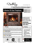
Installation & Maintenance Manual
H38VO-ST
HL38VO-ST
Outdoor Ventless
See Through
Residential
Gas Fireplace
DANGER
Read and understand this manual. Improper installation, adjustment, alteration,
service or maintenance can cause serious injury, property damage or even death.
For assistance or additional information consult a qualified installer, service
agency or the gas supplier.
CAUTION
Glass doors on gas fireplaces are extremely hot while the fireplace is on and
remain hot even after the fireplace has been turned off. Safety screens are
available and can reduce the risks of severe burns. Please keep children away
from the fireplace at all times.
WARNING
FOR OUTDOOR USE ONLY.
WARNING
Do not store or use gasoline or any other flammable vapors and liquids in the vicinity of
this or any other gas burning appliance. A fire or explosion my occur causing serious
injury, property damage or even death.
NOTICE
Installer: Leave this manual with the appliance. Do not remove.
Consumer: Retain this manual for maintenance and future reference. Do not Discard.
DANGER
If you smell gas:
1. Shut off gas to the appliance.
2. Extinguish any open flame.
3. If odor continues, keep away from the appliance and
immediately call your gas supplier or fire department.
WARNING
®
C
XG0817
US
CARBON MONOXIDE HAZARD
This appliance can produce carbon monoxide which has
no odor. Using it in an enclosed space can kill you.
Never use this appliance in an enclosed space such as a
camper, tent, car or home.
Canadian Heating Products Inc. Langley, BC V4W 4A1 | Montigo Del Ray Corp. Ferndale, WA 98248
080311
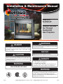
H*38SVO-ST Outdoor Gas Fireplace
NOTICE
You must read and understand this
manual prior to installation, operation or
troubleshooting this appliance. Please
retain this owner’s manual for furure
reference and maintenance.
XW2010
Table of Contents
Introduction ..................................................................................3
Models ..................................................................................3
Installation
Before you Start ..................................................................................4
Installation Checklist................................................................................4
Section 1: Installation Overview and Product Dimensions......................5
Section 2: Framing the Fireplace............................................................6
Clearances .............................................................................6 - 7
Finishing around the Fireplace............................................................7
Section 3: Venting.............................................................................. N/A
Section 4: Wiring ..................................................................................8
▪ Honeywell gas control and pilot . .............................................8
Section 5: Installing the Gas Line............................................................9
Section 5-1: Fuel Conversion...................................................................9
Section 5-2: Gas Pressure.......................................................................9
Section 5-3: Gas Connection...................................................................9
Section 6: .............................................................................. N/A
Section 7: Installing and Removing the Door........................................10
Section 8: Installing the Accessories..............................................11 - 14
▪ Installing the H34VO Log Set..................................................... 11
▪ Installing the H38VO Log Set.....................................................12
▪ Installing the H42VO Log Set.....................................................13
▪ Installing the HL38VO Firestones...............................................14
Section 9: Operation.........................................................15 - 16
▪ Start-up Sequence with Continuous Pilot...................................15
▪ Start-up Sequence with Honeywell Electronic Ignition..............16
Maintenance
........................................................................17 - 18
▪ General ................................................................................17
▪ Cleaning ................................................................................17
▪ Hi-Lo Burner Adjustment.............................................................17
▪ Pilot Burner Adjustment..............................................................17
▪ Replacement Parts.....................................................................18
Appendix
A. Termination Locations...............................................................19
B. Warranty ................................................................................20
C. State of Massachusetts............................................................21
Page 2
XG0817 - 080311
H*38SVO-ST Outdoor Gas Fireplace
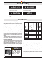
Safety Alert Key
DANGER
WARNING
Indicates a hazardous situation which, if not
avoided, WILL result in death or serious
injury or property damage.
Indicates a hazardous situation which, if not
avoided, COULD result in death or serious
injury or property damage.
CAUTION
NOTICE
Indicates a hazardous situation which, if not
avoided, WILL result in minor or moderate
injury.
Address practices that are important, but
not related to personal injury
How to use this manual:
This manual covers installation, operation and maintenance. Lighting,
operation and care of this fireplace can be easily performed by the
homeowner. However, all installation and service work should be
performed by a qualified or licensed installer, plumber, or gasfitter who
is qualified or licensed by the state, province, region, or governing body
in which the appliance is being installed.
Blank
Flammable materials
General Warning
Explosion risk
Toxic
Corrosive
Danger overhead crane
Biohazard
Oxidising
Traditional Burner /
Logset
Contemporary
Burner w/River rock
Linear Burner w/
Glass Accessories
Standing Pilot
Ignition
Honeywell Hot
Surface Ignition
X
45,000
X
H38VOSTNI
X
45,000
X
H38VOSTL
X
45,000
X
H38VOSTLI
X
45,000
X
HL38VOSTN
X
X
X
X
X
45,000
X
HL38VOSTNI X
45,000
X
HL38VOSTL
X
45,000
X
HL38VOSTLI
X
45,000
X
X
X
X
X
Warranty and Installation Information: (See Appendix B)
The Montigo warranty will be voided by, and Montigo disclaims any
responsibility for, the following actions:
► Modification of the fireplace and/or components including
Direct-Vent assembly or glass doors.
► Use of any component part not manufactured or approved by
Montigo in combination with this Montigo fireplace system.
► Installation other than as instructed in this manual.
Consult your local Gas Inspection Branch on installation requirements
for factory-built gas fireplaces. Installation & repairs should be done by
a qualified contractor.
High voltage
Hot surface
Danger of entrapment
Danger of death
Hot glass will cause
burns.
Do not touch
glass until unit is cooled.
Never allow children to
touch glass.
XG0817 - 080311
H38VOSTN
Fork lift trucks
WARNING
Laser Radiation
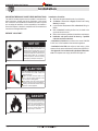
MODEL
Congratulations on your purchase of a Montigo Fireplace.
With over 30 years of experience, Montigo is committed to providing you
with a gas fireplace that is not only a beautiful addition to your space, but
that is also designed and manufactured to the highest safety, reliability
and engineering standards.
We strongly encourage you to read and carefully follow the instructions
laid out in this Installation, Operation and Maintenance Manual and retain
it for your future reference. Pay special attention to all cautions, warnings,
and notices throughout this manual intended to ensure your safety.
This manual covers installation, operation and maintenance. Lighting,
operation and care of this fireplace can be easily performed by the
homeowner. All installation and service work should be performed by
a qualified or licensed installer, plumber or gas fitter as certified by the
state, province, region or governing body where the fireplace is being
installed.
This installation, operation and maintenance manual is applicable to the
models described. Refer to your rating plate to verify included options.
Natural Gas
Liquid Propane
Gas Rating
(BTU hr)
Introduction
Irritant
Slippery floor
Watch your step
Cutting
High temperatures
Glass hazard
Danger of suffocation
Gas bottles
Watch for
falling objects
Electricity
Danger for cutter
Entrapment hazard
Battery hazard
Rotating parts
Low temperature
Strong magnetic field
Optical radiation
Non ionizing
radiation
Radiation
Hazardous to the
Environment
Danger of harming
your hands
Page 3
H*38SVO-ST Outdoor Gas Fireplace
Installation
IMPORTANT MESSAGE: SAVE THESE INSTRUCTIONS
The H38SVO Ventless fireplace must be installed in accordance with
these Instructions. Carefully read all the Instructions in this manual
first. Consult the Local Gas Branch to determine the need for a permit
prior to starting the installation. It is the responsibility of the installer to
ensure this fireplace is installed in compliance with the manufacturers
instructions and all applicable codes.
BEFORE YOU START:
NOTICE
Installation and repairs should be done by an
authorized gas fireplace service technician. The
appliance should be inspected before use and at
least annually by a professional. More frequesnt
cleaning may be required due to exessive lint from
carpeting, bedding material, ect. It is imperative
that control compartments, burners and circulating
air passageways of the fireplace are kept clean.
Installation Checklist
Determine the desired install location of your fireplace.
See Section 1, Dimensions on Page 5, and refer to the Framing
Section 2 for details.
Layout Electrical Requirements Refer to Section 4: Wiring, for
Details.
Refer to Section 5: Installing the Gas Line, for details on the
gas connection and access.
Refer to local codes and guidelines for installation requirements.
Installation and repairs should be done by a qualified
contractor and must conform to:
• Installations in Canada must conform to the current CAN/CGA
B-149.1 and .2 Gas Installation Code and local regulations.
• Installations in the USA must conform to local codes, or in the
absence of local codes to the National Fuel Gas Code, ANSI Z223.1.
• See Appendix C for installation within the State of Massachusetts. This fireplace must comply with NFPA-54 Chapter 10.
XW2016
CAUTION
Due to high operating temperatures, this appliance
should be located out of traffic & away from
furniture and draperies.
Children and adults should be alerted to the
hazards of the high surface temperature, which
could cause burns or clothing ignition.
Young children should be carefully supervised
when they are in the same room as the appliance.
Clothing or other flammable materials should not
be placed on or near the appliance.
Blank
Flammable materials
Explosion risk
Toxic
Corrosive
Danger overhead crane
Fork lift trucks
High voltage
General Warning
Laser Radiation
Biohazard
Oxidising
Hot surface
Danger of entrapment
Danger of death
Watch your step
Danger of suffocation
Blank
Irritant
Slippery floor
Cutting
High temperatures
Glass hazard
Flammable materials
Explosion risk
Toxic
Corrosive
Danger overhead crane
Fork lift trucks
Gas bottles
Watch for
falling objects
Electricity
Danger for cutter
Entrapment hazard
Battery hazard
Rotating parts
General Warning
Laser Radiation
Biohazard
Oxidising
Hot surface
Danger of entrapment
Danger of death
High voltage
Blank
XW2018
Low temperature
Strong magnetic field
Optical radiation
Non ionizing
radiation
Radiation
Hazardous to the
Environment
Flammable materials
Explosion risk
Toxic
Corrosive
Danger overhead crane
Fork lift trucks
High voltage
Irritant
Slippery floor
Watch your step
Cutting
High temperatures
Glass hazard
Danger of suffocation
General Warning
Laser Radiation
Biohazard
Oxidising
Hot surface
Danger of entrapment
Danger of death
Gas bottles
Watch for
falling objects
Electricity
Danger for cutter
Entrapment hazard
Battery hazard
Rotating parts
Cutting
Danger of harming
your hands
Irritant
Slippery floor
Watch your step
High temperatures
Glass hazard
Danger of suffocation
Low temperature
Strong magnetic field
Optical radiation
Non ionizing
radiation
Radiation
Hazardous to the
Environment
Danger of harming
your hands
Gas bottles
Watch for
Electricity
Danger for cutter
Entrapment hazard
Battery hazard
Rotating parts
XW2020-When-Installed_[EN].pdf
1
1/24/2011
12:48:53 PM
DANGER
When this appliance is installed directly
on any combustible material other than
wood flooring, it must be installed on a
metal or wood panel extending the full
width and depth of the appliance or a
fire will occur causing serious injury,
property damage or even death.
XW2020
Page 4
XG0817 - 080311
H*38SVO-ST Outdoor Gas Fireplace
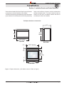
Installation
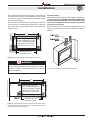
Section 1: Installation Overview and Product Dimensions
Please review the Installation Checklist on Page 4 for general information
on preparing for a successful installation of your fireplace.
The H-Series VO fireplace may be installed in any location that maintains
proper clearances to air conditioning ducts, electrical wiring and plumbing.
Safety, as well as efficiency of operation, should be considered when
selecting the fireplace location. Try to select a location that does not
interfere with room traffic, has adequate ventilation and offers an
accessible path for Direct Vent installation.
The fireplace dimensions are shown below:
24"
24"
36½"
Height
24”
36½"
Height
24”
36⅞" Width
Top View
36⅞" Width
Top View
1¼"
1¼"
Side View
35⅝" Opening
41"
35⅝" Opening
6¾"
1¼"
6¾"
1¼"
5¼"
36⅞" Width
Front View
41"
Surrounding construct
(bottom, sides and top
25¾" construction
Surrounding
be non-combustible ma
Opening
(bottom,
sides and top) must metal studs, concrete b
be non-combustible materials, and concrete, brick, or
metal studs, concrete board
and concrete,
brick, or stone.
5¼"
25¾"
Opening
1"
1"
Side View
36⅞" Width
Front View
Backframe Min. 38"
both sides Typical
Backframe Min. 38
both sides Typical
Figure 1. Fireplace dimensions, (ALL Models, shown in Table on Page 3).
41"
41"
XG0817 - 080311
Shaded area non c
framing. Both wa
Shaded area non combustible May not be exactly
framing. Both walls Typical.
May not be exactly as shown.
Page 5
Surrounding construction
(bottom, sides and top) must
be non-combustible materials,
metal studs, concrete board
and concrete, brick, or stone.
H*38SVO-ST Outdoor Gas Fireplace
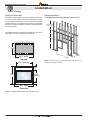
Installation
Section 2: Framing
Backframe Min. 38"
both sides Typical
Installing The Fireplace Shell
The fireplace may be installed in a location that maintains clearances to
ALL exterior furniture, appliances and other exterior equipment. Safety,
as well as efficiency of operation, must be considered when selecting
the fireplace location. Try to select a location that does not interfere with
foot traffic, has adequate ventilation, and offers an accessible pathway
for ventilated gasses.
Framing (stand-alone):
For Fireplace without the Optional Stainless steel surround.
Combustible
materials
1" clearance
The fireplace dimensions with the Optional Stainless
steelonly
cover, shown
to corners
below. (Note: This model is intended as a stand-alone).
1” Clearance to
combustibles to sides
ot Unit
36”
38”
25⅛”
40”
41”
40⅛" Width
Top View
23 7/8”
Figure 3. Framing dimensions (without Optional surround). Must be back-
35⅜" Opening
framed as shown in Figure 2a below.
6¾"
25¾"
Opening
37⅝"
5¼"
40⅛" Width
Front View
Figure 2. Fireplace dimensions with insulation jacket
Page 6
XG0817 - 080311
H*38SVO-ST Outdoor Gas Fireplace
Existing Combustible Structure
41"
Installation
Surrounding construction
(bottom, sides and top) must
non-combustible
When installing this fireplace asbeshown
in Figure 5, thematerials,
outer shell is not
studs,
concrete
to be installed. Follow Figures metal
4,5 (wall
installation)
andboard
Figure 3 (MIN
andcontemporary
concrete, brick,
or stone.
size enclosure for patio or other
installation)
to frame
around the fireplace chassis.
Note: ONLY Non-combustible materials must be used in construction
of the enclosure. (top, bottom and Backframe
sides). SteelMin.
studs38"
in combination
with concrete, rock, or stone finishing
are acceptable. See
bothmaterials,
sides Typical
Figures 3, 4 and 5.
Fireplace Facing
When selecting the finish material for your fireplace, it is important to
remember the following: THE LOWER GAS CONTROL PANEL MUST
NOT BE OBSTRUCTED IN ANY WAY - to do so restricts the air supply
for the control compartments and heat exchanger it also prevents
access for servicing controls.
Decorative facing must not extend past the fireplace opening at all,
because it will interfere with the access to retainers for removal of
glass door.
41"
Surrounding construction
(bottom, sides and top) must
be non-combustible materials,
metal studs, concrete board
and concrete, brick, or stone.
Backframe Min. 38"
both sides Typical
Figure 4. Back framing dimensions. (without Optional surround)
WARNING!
Combustible
When this appliance is installedmaterials
directly on exterior carpeting, tile
or any combustible material other than wood flooring, it must be
installed on a metal or wood panel extending the full width and
depth
of the appliance.
1" clearance
Existing Combustible Structure
to corners only
Figure 6. Non-combustible surrounds and sidewall clearances.
36”
41"
1” Clearance to
combustibles to sides
ot Unit
38”
Surrounding construction
(bottom, sides and top) must
be non-combustible materials,
metal studs, concrete board
and concrete, brick, or stone.
40”
41”
23 7/8”
Backframe Min. 38"
both sides Typical
Figure 5. Framing dimensions (without Optional surround). Distance from
Existing Structures. (Please follow Appendix A - Termination locations, when
41"
considering a location for your fireplace).
Surrounding construction
(bottom, sides and top) must
be non-combustible materials,
XG0817 - 080311
metal studs, concrete board
and concrete, brick, or stone.
Page 7
H*38SVO-ST Outdoor Gas Fireplace
Installation
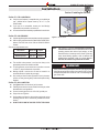
Section 4: Wiring
Honeywell (Q3450)
Pilot Assembly
Pilot Electrical
Harness Connector
Honeywell Gas
Control (SV9501M)
Gas Control
Connector
Source 110V
Distribution
Panel
Wall
Switch
White
Water tight
Electrical box
Black
Figure 7. Wiring for the H38SVO Honeywell gas control and pilot.
Power
Generator
Pilot Adjsutment Screw
Wall Switch
Inlet Pressure
Manifold Pressure
Test Connection
Figure 8. Standing Pilot Diagram
Installing The Remote Switch
The H38 SVO's gas valve, located behind the lower trim, may be
connected to a wall switch. The valve generates its own power on a
millivolt circuit. Use only low voltage wire, and DO NOT connect
any external power to it.
Refer to Figure 4 for wiring requirements.
Note: The switch location must not exceed 30' from the fireplace.
Page 8
WARNING!
Montigo Part No. #HSIT07 must be encased in a water-tight
electrical box OR ensure the box is installed in a dry location
and avoid any moisture. If installed outdoors, ensure you also
install a Ground Fault Interrupt per local code.
XG0817 - 080311
H*38SVO-ST Outdoor Gas Fireplace
Installation
Section 5: Installing the Gas Line
Section 5-1: FUEL CONVERSION
Verify that your fireplace is compatible with your available gas
type. (Natural Gas or Propane shown by "N" or "L" in your
model number
If gas type is not compatible, contact your local Montigo
representative to purchase a conversion kit.
Conversion kits must be installed by a qualified service technician.
Section 5-2: GAS PRESSURE
Optimum appliance performance requires proper input pressures.
Gas line sizing requirements will be determined in ANSI Z223.1
National Fuel Gas Code in the USA and CAN/CGA B149 in
Canada.
Pressure requirements are:
Gas Pressure
Natural Gas
Propane
Minimum inlet pressure
5.5in. w.c.
11in. w.c.
Manifold pressure
3.5in. w.c.
10in. w.c.
The manifold outlet pressure is set from the factory to the
appropriate pressure but should be verified.
To check pressures, control valves have a provision to remove
a 1/8” N.PT. plug to be fitted with a hose barb.
Montigo requires a service shut off valve be located in an
accessible location to isolate the gas supply.
Only install gas shut-off valves approved for use by the state,
province, or other governing body in which the fireplace is being
installed.
Gasline Access
0.875” dia.
2”
7”
to center
Figure 9. Gas line access.
Note:
After gas line is connected, each appliance connection,
valve and valve train must be checked while under normal
operating pressure with either a liquid solution, or leak
detection device, to locate any source of leak. Tighten any
areas where bubbling appears or leak is detected until
bubbling stops completely or leak is no longer detected.
DO NOT use a flame of any kind to test for leaks.
WARNING!
When pressure testing the fireplace, Gas line, and input system
follow the appropriate local codes or your area. DO NOT connect
the fireplace to pressures in excess of 1/2lb. This will damage the
gas control valve.
Section 5-3: GAS CONNECTION
See Figure 5 below for location of gas line access.
Flexible gas connectors must not exceed 3 feet in length, unless
allowable within local regulations.
Connect incoming gas line to the 1/2"or 3/8" gas inlet port.
Purge all air out of gas line.
Check appliance connection, valve and valve train under normal
operating pressure with a commercially available leak check
solution.
DO NOT USE A FLAME OF ANY KIND TO TEST FOR LEAKS.
XG0817 - 080311
Page 9
H*38SVO-ST Outdoor Gas Fireplace
Installation
Section:
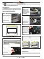
Section 7: Installing & Removing the Door
Removing the door:
The H-Series VO doors are removed in a few simple steps. Follow these
below to remove the Horizontal access panel, unlatch the door buckles
and, remove the door. Replace in reverse order.
Remove the Horizontal Access Panel:
Step 1: Remove the Horizontal Access Panel:
Remove the Horizontal cover
by placing fingers in both finger
holes, then pushing away from
you and lifting out. Place it
Finger Holes
aside during maintenance or
cleaning.
Installed Gas
Install in reverse order.
Valve Cover
Figure 10. Removing and installing the Horizontal Access Panel
Step 2:
Locate the Door Buckles:
Step 5:
Ensure the tool is firmly
in the lower end of the
slot, (as shown), Then pull
toward you (Caution: hold
the tool securely).
2
Figure 10d.
Step 6:
Pull hard if necessary to
release the spring tension. (Caution: The latch
springs back with force,
hold the tool securely).
3
Figure 10e.
Step 7:
Remove the tool from
the latch slot. Ensure the
latches are hanging freely,
the hook end is released
from the bottom of the door.
(Repeat all 4-steps for the
remaining latches).
4
Figure 10f.
Step 8:
Figure 10a. Locate the door buckles. (Both Sides Typical)
Step 3:
Removing the Door:
Grasp the Door on either side, usually midway and lift upward, lift
the door carefully up and away from the front of the fireplace. See
Figures 7g. Place the Door aside in a safe place while maintenance
and / or cleaning is being performed.
Release the Door Buckles
Hand-hold
Door Latch Slot
Door Latch Hook
Figure 10b. Door buckle Tool
Step 4:
Firmly grasp hand-hold
end of Door buckle tool
and place the machined
end in the slot under door
frame. (as shown)
Figure 10g. Removing and installing the glass doors. (Both Sides Typical)
1
Installing the Door:
To install the door, hook the top edge of the door frame into place. Lower
the door into position and follow the previous steps shown in reverse order.
Figure 10c.
Page 10
XG0817 - 080311
H*38SVO-ST Outdoor Gas Fireplace
Installation
Section 8: Installing the Accessories
Installing the Logs and Embers
Bottom Logs
The H38VO-ST is supplied with eight (8) fibre logs. The two small bottom
logs ("A" ) are mounted on the burner grate by placing them diagonally
onto the supplied Log stands. The long Front / Back logs ("B") are
placed against the grate as shown in Figure 11c. Note: When placing
logs, arrange Logs "B" as not to cover Burner holes.
Top Logs
Next are the logs "C" which are placed diagonally, as shown in Figure
24d. The last Logs "D" are then mounted on top of logs "A" as shown
in Figure 11e.
Log C
Log C
Figure 11d. Log Installation. (Place Logs' "C" on-top of Logs "A".
Indentations on-top of Logs' "A"
WARNING: If logs are not placed properly, excessive sooting will result.
Log D
Burner holes (front & back burner),
note hole pattern when placing logs
Log Stand
Air Inlets
Log Stand
Log D
Burners
Figure 11e. Completed Installation.
Front of Fireplace
Figure 11a. (Empty firebox showing the Left & Right stands).
Log A
Log A
Figure 11b. (Place Logs' "A" on Left & Right stands).
Log B
Log B
Figure 11c. (Place Logs' "B" as shown, in front of Right-hand "A", and
behind Left-hand "B".
XG0817 - 080311
Page 11
H*38SVO-ST Outdoor Gas Fireplace
Installation
WARNING!
Do not attempt to clean glass when hot.
L42DF-ST
Do not clean glass with abrasive materials as any glass etching may
cause premature glass failure.
Do not operate this fireplace without the glass door, or with a broken
glass door.
Installing the Glass Beads
This fireplace is supplied with Designer Glass beads. Remove the
Door and trim as shown on page 10 and follow these instructions to
ensure all parts are removed or replaced as required.
Once the Trim and glass doors are removed place the glass beads
randomly across the pan surrounding the burners as shown in Figure 12.
NOTE: DO NOT Cover burners with beads or the optional rocks, as
shown in Figure 12.
Note: Ensure the rocks or beads do not cover the Burners.
Figure 29. Installation of glass beads .
Page 12
XG0817 - 080311
H*38SVO-ST Outdoor Gas Fireplace
Operation
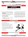
Section 9: Start-up Sequence
with Continuous Pilot
For Your
Safety
- READ
BEFORE
LIGHTING:
with
American
Flame Electronic
Ignition
WARNING
If the information in these instructions is not followed exactly, a fire or explosion may
result causing property damage, personal injury or death.
A. This appliance has a pilot which must be lighted by hand.
When lighting the pilot, follow these instructions exactly.
B. BEFORE LIGHTING smell all around the appliance area for
gas. Be sure to smell next to the floor because some gas is
heavier than air and will settle on the floor.
What To Do If You Smell Gas:
Do not try to light any appliance.
Do not touch any electrical switch; do not use any phone in
your building.
Immediately call your gas supplier from a neighbour's phone.
Follow the gas supplier's instructions.
If you cannot reach your gas supplier, call the Fire Department.
C. Use only your hand to push in or turn the gas control knob.
Never use tools. If the knob will not push in or turn by hand,
don't try to repair it, call a qualified service technician. Force
or attempt to repair may result in a fire or explosion.
D. Do not use this appliance if any part has been under water.
Immediately call a qualified service technician to inspect the
appliance and to replace any part of the control system, and
any gas control which has been under water.
Lighting Instructions:
1.
2.
3.
4.
STOP! Read the safety information above on this label.
Lift out the lower Horizontal access panel.
Push in gas control knob and turn clockwise
to "OFF."
Wait five (5) minutes to clear out any gas. Smell for gas,
including near the floor. If you then smell gas, STOP! Follow
"B" in the safety information above on this label. If you don't
smell gas, go to the next step.
5. Locate pilot burner (See illustration at right.) and follow steps
below.
6. Turn knob on gas control counter clockwise
to "PILOT."
7. Push in gas control knob completely and hold. Light with Piezo
Igniter button. Continue to hold the control knob in for about
(1) minute after the pilot is lit. Release the knob and it will pop
back up. Pilot should remain lit. If it goes out repeat steps 3
through 8.
If knob does not pop up when released. Stop and immediately
call your service technician or gas supplier.
If the pilot will not stay lit after several tries, turn the gas control
knob to "OFF" and call your service technician or gas supplier.
8. Push in gas control knob and turn counter-clockwise
"ON."
9. Replace the lower Horizontal access
panel.
10. Turn on remote switch to ignite fire.
to
NOTE: Gas control knob cannot be turned from "PILOT" to "OFF"
unless knob is pushed in slightly. Do not force.
To Turn Off Gas To Appliance:
1. Turn off remote switch.
2. Lift out the lower Horizontal access panel.
XG0817 - 080311
3. Push in gas control knob slightly and turn
"Off". Do not force.
4. Replace the lower Horizontal access panel.
clockwise to
Page 13
H*38SVO-ST Outdoor Gas Fireplace
Operation
Section:
with Honeywell Electronic Ignition
For Your
Safety
- READ
BEFORE
LIGHTING:
with
American
Flame Electronic
Ignition
WARNING
If the information in these instructions is not followed exactly, a fire or explosion may
result causing property damage, personal injury or death.
A. This appliance is equipped with an ignition system that
lights the pilot burner automatically. Do not attempt to light
the pilot by hand.
B. BEFORE LIGHTING smell all around the appliance area for
gas. Be sure to smell next to the floor because some gas is
heavier than air and will settle on the floor.
What To Do If You Smell Gas:
Do not try to light any appliance.
Do not touch any electrical switch; do not use any phone in
your building.
Immediately call your gas supplier from a neighbour's phone.
Follow the gas supplier's instructions.
If you cannot reach your gas supplier, call the Fire Department.
C. Use only your hand to push in or turn the gas control knob.
Never use tools. If the knob will not push in or turn by
hand, don't try to repair it, call a qualified service technician.
Force or attempt to repair may result in a fire or explosion.
D. Do not use this appliance if any part has been under water.
Immediately call a qualified service technician to inspect
the appliance and to replace any part of the control system,
and any gas control which has been under water.
Lighting Instructions:
1. STOP! Read the safety information above on this label.
2. Flip down the lower trims.
3. Turn switch on the gas control to OFF".
8. If the fireplace does not operate, follow the instructions "To
Turn Off Gas To Appliance" and call your service technician
or gas supplier.
4. Wait 5 minutes to clear out any gas. If you smell gas,
STOP! Follow "B" in the safety information above on this
label. If you don't smell gas, go to the next step.
5. Turn switch on the gas control to "ON". NOTE: This unit is
equipped with an ignition system that lights the pilot burner
automatically. Do not attempt to light the pilot by hand.
Gas
Inlet
6. Turn on wall switch.
7. Flip up the lower trim.
Gas Control Switch
Shown in "On" Position
To Turn Off Gas To Appliance:
1. Turn off remote switch.
2. Flip down the lower trim.
Page 14
3. Turn the switch on the gas control to "Off".
4. Flip up the trim.
XG0817 - 080311
H*38SVO-ST Outdoor Gas Fireplace
Maintenance
Section:
Lighting Instructions
See pages 13 to 14.
General
Have the fireplace and installation inspected yearly. The
inspection must include, but is not limited to, the following:
• A visual check of the entire vent system and termination.
• An inspection of the explosion relief flappers and the door
gaskets to ensure a proper seal.
• An inspection of the burner, vent run, and primary air openings.
• An inspection of the gas valve, gas components, and pilot
flame. For your convenience a 1/8" manifold pressure tap is
supplied on the gas valve for a test gauge connection.
• Ensure proper log placement as per this manual.
• Inspection of all optional equipment; fans, thermostats, etc.
For Natural Gas this appliance requires a minimum inlet pressure
of 5.5" W.C. and a manifold pressure of 3.5" W.C.
For Propane Gas this appliance requires a minimum inlet
pressure of 11" W.C. and a manifold pressure of 10" W.C.
Always keep the fireplace area clear and free of combustible
materials, as well as gasoline and other flammable vapours
and liquids.
Do not use this appliance if any part has been under water.
Immediately call a qualified service technician to inspect the
appliance and to replace any part of the control system and any
gas control which has been under water.
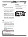
Burner Adjustment
The H-Series VOST is equipped with an adjustable burner, allowing
you to raise or lower the flames. To adjust the flames, locate the black
knob marked 'Hi-Lo', in the centre of the gas control valve (See Figure
11). The front burners are not adjustable.
To raise the flame height, turn the black knob (located behind the
lower trim) counterclockwise.
To lower the flame height, turn clockwise.
'Hi-Lo' Adjustment Knob
Gas Control Knob
(Shown in "Pilot" postion.)
Figure 12.'Hi-Lo' Adjustment on the H-Series VO's gas valve.
Cleaning
When the fireplace is first activated, there may be some smoking and
a visible film may be left on the glass. This is a normal condition, and is
the result of burning of protective coatings on new metal.
Glass must be cleaned periodically to remove any film (which is
a normal by-product of combustion) which may be visible. Film
can easily be removed by removing the door, as shown on Page
20. Handle the door carefully, and clean it with non-abrasive
glass cleaners. One of the most effective products is Kel Kem.
Silicone seals on inner door during initial firing will "off gas",
leaving a visual deposit of a white substance on combustion
chamber walls. This can easily be removed using normal
household products.
Use a vacuum cleaner or whisk broom to keep the control
compartment, burner, and firebox free from dust and lint. Logs may be cleaned periodically with a vacuum to remove soot
or other contaminates.
CAUTION!
Fireplace gas control must be in the “OFF” position and pilot
and main burners extinguished when cleaning appliance with
a vacuum.
Doors can get very hot. Handle only when cool.
XG0817 - 080311
Page 15
H*38SVO-ST Outdoor Gas Fireplace
Maintenance
Gas Control Valve
Pilot Adjsutment Screw
Troubleshooting
Power
Generator
Wall Switch
Inlet Pressure
Manifold Pressure
Test Connection
Figure 33. Sit Nova 820 gas valve.
Pilot Burner Adjustment
1. Locate Pilot Adjustment Screw. (See figure 33.)
2. Adjust pilot screw to provide properly sized flame as shown in
figure 34).
3. After installing or servicing, leak test with a soap solution with main
burner on. Coat pipe and tubing joints, gasket etc. with soap solution.
Bubbles indicate leaks. Tighten any areas where the bubbles appear
until the bubbling stops completely.
Figure 34. Pilot Burner.
Troubleshooting
The following is a troubleshooting chart of possible problems:
PROBLEM CORRECTIVE ACTION
Noisy Pilot Flame
Locate pilot adjustement screw on
gas control valve. Flame is decreased by
turning adjustment screw clockwise.
Pilot won’t ignite Disconnect remote wires and try to
light pilot. If pilot now works, remote
connections are faulty. Check wiring
diagram figure 33.
Main burner will
not light
1. Check wiring (see figure 33).
2. Check wall switch for proper
connection.
Page 16
If your fireplace still does not operate correctly, consult your dealer or
the manufacturer.
All service and repairs should be performed by a qualified agency.
All spare parts, optional fans, and optional trim finishes are available
from your local dealer or the manufacturer.
XG0817 - 080311
H*38SVO-ST Outdoor Gas Fireplace
Appendix
Appendix B Warranty:
The Warranty
The Companies warrants the Montigo Gas Appliance to be free from defects in materials and workmanship at the time of manufacture. On the Montigo fireplace,
there is a ten-year warranty on the firebox and its components, a five-year warranty on the main burner and pilot burner, and a one-year warranty on the gas control
valve, fibre logs and Power Vent Module. The Glass, plated / painted finishes, and refractory lining are exempt from the warranty.
Remedy And Exclusions
The coverage of this Warranty is limited to all components of the Gas Appliance manufactured by The Companies.
This Warranty only covers Montigo Gas Appliances installed in the United States or Canada.
If the components of the Gas Appliance covered by this Warranty are found to be defective within the time frame stated (see The Companies right of investigation
outlined below). The Companies will, at its option, replace or repair defective components of the Gas Appliance manufactured by The Companies at no charge,
and will also pay for reasonable labour costs incurred in replacing or repairing components. If repair or replacement is not commercially practical, The Companies
will, at its option, refund the purchase price of the Montigo Gas Appliance.
This Warranty covers only parts and labour as provided above. In no case shall The Companies be responsible for materials, components, or construction which
are not manufactured or supplied by The Companies, or for the labour necessary to install, repair or remove such materials, components or construction. All
replacement or repair components will be shipped F.O.B. the nearest The Companies factory.
Qualifications To The Warranty
The Gas Appliance Warranty outlined above is further subject to the following qualifications:
(1) The Gas Appliance must be installed in accordance with The Companies installation instructions and local building codes. The Warranty on this Montigo
Gas Appliance covers only the component parts manufactured by The Companies. The use of components manufactured by others with this Montigo Gas
Appliance could create serious safety hazards, may result in the denial of certification by recognized national safety agencies, and could be in violation of
local building codes. This warranty does not cover any damages occurring from the use of any components not manufactured or supplied by The Companies
(2) The Montigo Gas Appliance must be subjected to normal use. The Gas Appliances are designed to burn gas only. Burning conventional fireplace fuels such
as wood, coal or any other solid fuel will cause damage to the Gas Appliance, will produce excessive temperatures and will result in a fire hazard.
Limitations On Liability
It is expressly agreed and understood that The Companies sole obligation, and purchaser's exclusive remedy under this Warranty, under any other warranty,
expressed or implied, or in contract, tort or otherwise, shall be limited to replacement, repair, or refund, as specified above.
In no event shall The Companies be responsible for any incidental or consequential damages caused by defects in its products, whether such damage occurs
or is discovered before or after replacement or repair, and whether or not such damage is caused by The Companies negligence. Some states do not allow the
exclusion or limitation of incidental or consequential damages, so the above limitation or exclusion may not apply to you. The duration of any implied warranty
with respect to this Montigo Gas Appliance is limited to the duration of the foregoing warranty. Some states do not allow limitation on how long an implied warranty
lasts, so the above may not apply to you.
Investigation Of Claims Against Warranty
The Companies reserves the right to investigate any and all claims against this Warranty and to decide upon method of settlement.
The Companies Are Not Responsible For Work Done Without Written Consent
The Companies shall in no event be responsible for any warranty work done without first obtaining The Companies written consent.
Dealers Have No Authority To Alter This Warranty
The Companies employees and dealers have no authority to make any warranties nor to authorize any remedies in addition to or inconsistent with those stated above.
How To Register A Claim Against Warranty
In order for any claim under this Warranty to be valid, The Companies must be notified of the claimed defect in writing or by telephone, as soon as reasonably
possible after the defect is discovered. Claims against this Warranty in writing should include the date of installation, and a description of the defect.
Other Rights
This Warranty gives you specific legal rights, and you may also have other rights which vary from state to state.
NOTE:
The Companies as stated above refer to - Canadian Heating Products Inc. and/or Montigo Del Ray Corp.
Canadian Heating Products Inc. and/or Montigo DelRay Corp. reserves the right to make changes at any time, without notice, in design, materials,
specifications, prices and also to discontinue colors, styles and products.
XG0817 - 080311
Page 17
H*38SVO-ST Outdoor Gas Fireplace
Appendix
Appendix C: State of Massachusetts
Amendment
(Gas Fireplace / Equipment sold in the State of Massachusetts)
5.08: Modifications to NFPA-54, Chapter 10
(1) Revise NFPA-54 section 10.5.4.2 by adding a second exception as follows:
Existing chimneys shall be permitted to have their use continued when a gas conversion burner is installed, and shall be equipped with a manually reset device
that will automatically shut off the gas to the burner in the event of a sustained back-draft.
(2) Revise 10.8.3 by adding the following additional requirements:
(a) For all side wall horizontally vented gas fueled equipment installed in every dwelling, building or structure used in whole or in part for residential purposes,
including those owned or operated by the Commonwealth and where the side wall exhaust vent termination is less than seven (7) feet above finished grade in
the area of the venting, including but not limited to decks and porches, the following requirements shall be satisfied:
1. INSTALLATION OF CARBON MONOXIDE DETECTORS. At the time of installation of the side wall horizontal vented gas fueled equipment, the installing plumber or gas fitter shall observe that a hard wired carbon monoxide detector with an alarm and battery back-up is installed on the floor
level where the gas equipment is to be installed. In addition, the installing plumber or gas fitter shall observe that a battery operated or hard wired carbon
monoxide detector with an alarm is installed on each additional level of the dwelling, building or structure served by the side wall horizontal vented gas fueled
equipment. It shall be the responsibility of the property owner to secure the services of qualified licensed professionals for the installation of hard wired carbon
monoxide detectors
a. In the event that the side wall horizontally vented gas fueled equipment is installed in a crawl space or an attic, the hard wired carbon monoxide detector with
alarm and battery back-up may be installed on the next adjacent floor level.
b. In the event that the requirements of this subdivision can not be met at the time of completion of installation, the owner shall have a period of thirty (30) days
to comply with the above requirements; provided, however, that during said thirty (30) day period, a battery operated carbon monoxide detector with an alarm
shall be installed.
2. APPROVED CARBON MONOXIDE DETECTORS. Each carbon monoxide detector as required in accordance with the above provisions
shall comply with NFPA 720 and be ANSI/UL 2034 listed and IAS certified.
3. SIGNAGE. A metal or plastic identification plate shall be permanently mounted to the exterior of the building at a minimum height of eight (8) feet
above grade directly in line with the exhaust vent terminal for the horizontally vented gas fueled heating appliance or equipment. The sign shall read, in print
size no less than one-half (1/2) inch in size, “GAS VENT DIRECTLY BELOW. KEEP CLEAR OF ALL OBSTRUCTIONS”.
4. INSPECTION. The state or local gas inspector of the side wall horizontally vented gas fueled equipment shall not approve the installation unless,
upon inspection, the inspector observes carbon monoxide detectors and signage installed in accordance with the provisions of 248 CMR 5.08(2)(a)1 through 4.
(b) EXEMPTIONS: The following equipment is exempt from 248 CMR 5.08(2)(a)1 through 4:
1. The equipment listed in Chapter 10 entitled “Equipment Not Required To Be Vented” in the most current edition of NFPA 54 as adopted by the
Board; and
2. Product Approved side wall horizontally vented gas fueled equipment installed in a room or structure separate from the dwelling, building or structure used in whole or in part for residential purposes. (c) MANUFACTURER REQUIREMENTS - GAS EQUIPMENT VENTING SYSTEM PROVIDED. When the manufacturer of Product
Approved side wall horizontally vented gas equipment provides a venting system design or venting system components with the equipment, the instructions
provided by the manufacturer for installation of the equipment and the venting system shall include:
1. Detailed instructions for the installation of the venting system design or the venting system components; and
2. A complete parts list for the venting system design or venting system.
(d) MANUFACTURER REQUIREMENTS - GAS EQUIPMENT VENTING SYSTEM NOT PROVIDED. When the manufacturer of a Product Approved side wall horizontally vented gas fueled equipment does not provide the parts for venting the flue gases, but identifies “special venting systems”,
the following requirements shall be satisfied by the manufacturer:
1. The referenced “special venting system” instructions shall be included with the appliance or equipment installation instructions; and
2. The “special venting systems” shall be Product Approved by the Board, and the instructions for that system shall include a parts list and
detailed installation instructions.
(e) A copy of all installation instructions for all Product Approved side wall horizontally vented gas fueled equipment, all venting instructions, all parts lists for
venting instructions, and/or all venting design instructions shall remain with the appliance or equipment at the completion of the installation.
(3) After NFPA-54 section 10.10.4.2 add a new section 10.10.4.3 as follows:
When more than four gas appliances are to be vented through a common gas vent or common horizontal vent manifold, a plan of the proposed vent installation
shall be submitted to the Inspector and the serving gas supplier for review and approval.
Extraction from: Massachusetts Rules and Regulations
5.00: Amendments To 2002 Edition Of ANSI Z223.1-NFPA-54
Page 18
XG0817 - 080311
H*38SVO-ST Outdoor Gas Fireplace
Notes
XG0817 - 080311
Page 19
H38VO ST
Outdoor Residential Gas Fireplace
Ferndale, Washington
TF: 1.800.789.6236
FX: 1.866.3000.0927
XG0817 - 080311
Langley, British Columbia
TF: 1.800.378.3115
FX: 1.604.607.6462