1
ADSL Ethernet Router Series
Protocols Discussed:
RFC 2684 (RFC 1483) Ethernet Framing
RFC 2684 (RFC 1483) IP Framing
RFC 2225 (RFC 1577) IPoA
RFC 2516 PPPoE
RFC 2364 PPPoA
Transparent Bridge
Te c h n i c a l M a n u a l
Version 1.5
© Copyright, December 2001. All Rights Reserved.
(P/N: 040-513447-151) (Ref: 9009000)
•
Virata is a registered trademark of Virata Corporation.
•
All other company or product names are trademarks or registered trademarks or
service marks of their respective owners and are hereby recognized as such.
Product warranty does not apply to damage caused by lightning, power surges or wrong
voltage usage.
Safety Guidelines
Adhere to the following safety guidelines when using your unit to reduce the risk of
fire, electric shock and injury.
○
!
Understand all instructions in the manual. Follow all instruction labels found
on the unit.
!
Except for the power adapter supplied, the unit should not be connected to
other adapters/power supplies.
!
Never spill liquid of any kind on the unit.
!
Do not place the unit on an unstable stand or table. The unit may drop and
become damaged.
!
Do not expose the unit to direct sunlight.
!
Do not put any heat generating devices close to the unit as it may degrade or
cause damage to it.
!
Do not stack the unit on top of each other. / Do not put any heavy object on
top of the unit
!
Do not use liquid cleaners or aerosol cleaners.
cleaning.
○
○
○
○
○
○
○
○
○
○
○
○
○
○
○
○
○
○
○
○
○
○
○
○
○
Use a soft, dry cloth for
○
○
○
○
○
○
○
○
○
○
○
iii
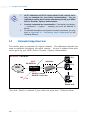
Contents
Safety Guidelines ......................................................................... iii
About This Manual ....................................................................... ix
Conventions Used ........................................................................ x
1.
2.
3.
Setting Up Local Management ................................................... 2-1
1.1
Setting up the Serial Link ................................................... 2-1
1.2
Configuring the Serial Link .................................................. 2-1
Basic Commands on Running Local Management ..................... 3-1
2.1
Guidelines ........................................................................ 3-1
2.2
Checking Your Router Performances ..................................... 3-2
2.3
Checking Your Router Entries .............................................. 3-2
2.4
To Disconnect/Connect the ADSL Link .................................. 3-3
2.5
To Toggle between Various Modes ........................................ 3-3
Configuring Your Router ........................................................... 4-1
3.1
Configuration Flow Chart .................................................... 4-1
3.2
Network Setup Overview .................................................... 4-2
3.3
Configuring the Basics ........................................................
3.3.1
Configuring the Basics:
Step 1 - Resetting your Router's Configuration .....
3.3.2
Configuring the Basics:
Step 2 - Configuring the LAN .............................
3.3.3
Configuring the Basics:
Step 3 - Configuring the WAN ............................
i)
Configuring the WAN - For RFC 2684
(RFC 1483) Ethernet Framing ..................
ii)
Configuring the WAN - For RFC 2684
(RFC 1483) IP Framing ...........................
iii)
Configuring the WAN - For RFC 2225
(RFC 1577) IPoA ....................................
iv)
Configuring the WAN - For RFC 2364 PPPoA .
v)
Configuring the WAN - For RFC 2516 PPPoE .
4-4
4-5
4-7
4-7
4-7
4-8
4-9
4-10
4-11
4.
3.3.4
Configuring the Basics:
Step 4 - Configuring the Routing Table ................ 4-12
3.3.5
Configuring the Basics:
Step 5 - Enabling IP Forwarding ......................... 4-12
3.3.6
3.3.7
Configuring the Basics: Step 6 - Enabling NAT .... 4-12
Configuring the Basics:
Step 7 - Saving the Configurations ...................... 4-12
3.4
Setting Up NAT Inbound Port Forwarding
(Port Address Translation) ................................................... 4-13
3.5
Configuring DHCP Server .................................................... 4-15
3.5.1
Some useful commands for DHCP ...................... 4-15
3.5.2
DHCP Ser ver Illustration .................................... 4-16
3.6
Configuring DNS Relay ....................................................... 4-17
3.6.1
To Enable DNS Relay (with fixed IP address from your
ADSL Service Provider) ...................................... 4-17
3.6.2
3.6.3
To Check DNS Relay Server Status ...................... 4-17
To Disable DNS Relay ........................................ 4-17
3.7
Setting Up SNMP .............................................................. 4-18
3.7.1
Read/Write Access ............................................ 4-18
3.7.2
SNMP Trap ....................................................... 4-19
3.8
Setting up Telnet Access ..................................................... 4-19
3.9
Configuring Autoloop for IP Interface .................................... 4-20
Configuring Your Transparent Bridge ........................................ 5-1
4.1
Network Setup Over view .................................................... 5-1
4.2
Configuring the Basics ........................................................ 5-1
4.2.1 Step 1: Resetting your Router's Configuration ....................... 5-2
4.2.2 Step 2: Configuring the LAN .............................................. 5-3
4.2.3 Step 3: Saving the Configurations ....................................... 5-3
5.
Router Configuration Examples................................................. 6-1
5.1
Example on RFC 2684 (RFC 1483) IP Framing .................... 6-1
5.2
Example on RFC 2364 PPPoA ............................................ 6-2
6.
Configuring PPTP (Point-to-Point Tunnelling Protocol) ........... 7-1
6.1
Running the Console Commands ......................................... 7-1
6.1.1
Step 1 - Configuring the LAN ............................. 7-1
6.1.2
6.1.3
6.2
Step 2 - Configuring PPP Client and PNS (PPTP
Network Server) ................................................ 7-1
Step 3 - Binding to Ethernet Interface ................ 7-2
Setting Up Dial-Up Networking ........................................... 7-2
6.2.1
Creating Dial-Up Networking .............................. 7-3
6.2.2
Establishing Your Internet Connection .................. 7-5
Appendix A - Commonly Used Commands ......................................... A-1
A.1
A.2
TCP/IP Commands ............................................................. A-1
A.1.1
autoloop ........................................................... A-1
A.1.2
A.1.3
A.1.4
config ............................................................... A-2
device .............................................................. A-3
ip device .......................................................... A-4
A.1.5
A.1.6
A.1.7
A.1.8
ipatm pvc ......................................................... A-5
relay ................................................................ A-6
rip accept ......................................................... A-7
rip send ............................................................ A-8
A.1.9
A.1.10
route ................................................................ A-9
snmp ................................................................ A-10
Bridge Commands ............................................................. A-11
A.2.1
device add ........................................................ A-11
A.2.2
A.2.3
A.2.4
A.3
A.4
device delete .................................................... A-12
device flush ...................................................... A-12
device list ......................................................... A-13
PPP Commands ................................................................ A-14
A.3.1
Console object types .......................................... A-14
A.3.2
Console examples .............................................. A-14
A.3.3
A.3.4
<channel> echo ever y ...................................... A-15
<channel> pppoe ............................................. A-16
A.3.5
A.3.6
A.3.7
<channel> pvc ................................................. A-18
<channel> welogin ........................................... A-19
user ................................................................. A-19
NAT Commands ................................................................ A-20
A.4.1
event ................................................................ A-20
A.4.2
A.4.3
A.4.4
inbound / Port Address Translation / Port Mapping A-21
info .................................................................. A-22
interfaces ......................................................... A-23
A.4.5
A.4.6
ip nat ............................................................... A-23
sessions ........................................................... A-24
A.5
A.6
DHCP Server Commands .................................................... A-25
A.5.1
config ............................................................... A-25
A.5.2
dnsrelay config .................................................. A-27
A.5.3
A.5.4
A.5.5
dnsrelay retry .................................................... A-28
dnsrelay server .................................................. A-28
dnsrelay status .................................................. A-29
A.5.6
A.5.7
A.5.8
A.5.9
dnsrelay trace/untrace .......................................
help .................................................................
status ...............................................................
version .............................................................
BUN Commands ............................................................... A-33
A.6.1
A.7
A-30
A-31
A-31
A-32
bun list channels ............................................... A-33
PPTP Commands .............................................................. A-34
A.7.1
Console object types .......................................... A-34
A.7.2
Console Examples .............................................. A-34
A.7.3
bind ................................................................. A-35
A.7.4
A.7.5
A.7.6
<tunnel> create ............................................... A-36
<tunnel> delete ............................................... A-37
<tunnel> info .................................................. A-37
A.7.7
list ................................................................... A-37
Appendix B - Well-Known TCP/UDP Ports ......................................... B-1
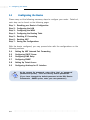
About This Manual
This manual is written for users who are familiar with console commands. It
contains instructions on how to configure your router for different network configurations.
Chapter 1 - Setting Up Local Management guides you on how to setup and establish
a communication link between your router and PC. With this local mangement
established, you can then start issuing console commands.
Chapter 2 - Basic Commands on Running Local Management gives the basic
commands to run the local management.
Chapter 3 - Configuring Your Router guides you on how to configure your router for
different network configurations. A Configuration Flow Chart is provided. The line
protocols discussed are RFC 2684 (RFC 1483) Ethernet Framing, RFC 2684 (RFC
1483) IP Framing, RFC 2225 (RFC 1577) IP over ATM, RFC 2364 PPPoA and RFC
2516 PPPoE. The configuring of NAT Inbound Port Forwarding, DHCP Server, DNS
Relay and so on, can also be found in this chapter.
Chapter 4 - Configuring Your Transparent Bridge guides you on how to configure
your router for transparent bridge.
Chapter 5 - Router Configuration Examples give you router configuration examples
based on RFC 2684 (RFC 1483) IP Framing and RFC 2364 PPPoA.
Chapter 6 - Configuring PPTP (Point-to-Point Tunnelling Protocol) guides you on the
console commands and setting up of the dial-up networking for PPTP.
You will be able to find detailed descriptions of the console commands at Appendix
A - Commonly Used Commands and the commonly used TCP/UDP Ports at Appendix
B - Well-Known TCP/UDP Ports.
○
○
○
○
○
○
○
○
○
○
○
○
○
○
○
○
○
○
○
○
○
○
○
○
○
○
○
○
○
○
○
○
○
○
○
○
○
ix
○ ○ ○ ○ ○ ADSL Ethernet Router Series Technical Manual
Conventions Used
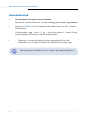
Text that appears in this style are console commands.
Example of console command: ip device add ppp_device ether //ppp/DEVICE=1
Numbers in italics are to be replaced with values from your ISP / System
Administrator.
In the example: ppp 1 pvc 0 35 ip , you are to replace 1, 0 and 35 with
actual values given from your System Administrator.
Numerics in superscript denote further explanation for the text.
Explanation can mostly be found at the bottom of the same page.
x
Note boxes are information that you need to pay special attention to.
x
○
○
○
○
○
○
○
○
○
○
○
○
○
○
○
○
○
○
○
○
○
○
○
○
○
○
○
○
○
○
○
○
○
○
○
○
○
○
1.
Setting Up Local Management
Local management refers to the process of managing and configuring the settings of
your router for your network environment. It is done via a PC connected to your
router.
Before running local management, communication between your router and your PC
has to be configured and established for them to 'understand each other'. You need
to setup a physical link between your router and the PC via a serial cable as
described in Section 1.1. Section 1.2 will show you how to configure the interface link
to allow communication between your PC and your router.
Setting up of local management needs only to be carried out once
for the same PC. However if you are connecting your router to
another PC, you will need to run section 1.1 and 1.2 again.
1.1
Setting up the Serial Link
i)
Connect one end of a serial cable to the COM Port (9-pin) of your PC and
the other end to the Serial Port (9-pin) of your router.
ii)
Connect your router to the Power Mains via the Power adaptor (that comes
with your package). You may refer to the User Manual for the illustrated
connection.
DO NOT POWER ON YOUR ROUTER SWITCH YET !
1.2
Configuring the Serial Link
i)
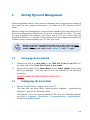
Run the HyperTerminal program from your PC.
(You may also use other Serial Communication Programs.
program is used as an illustration here).
HyperTerminal
For example, if you are running Windows® 98, from your Windows taskbar,
click Start > Programs > Accessories > Communications > HyperTerminal.
Double-click HyperTerminal.
○
○
○
○
○
○
○
○
○
○
○
○
○
○
○
○
○
○
○
○
○
○
○
○
○
○
○
○
○
○
○
○
○
○
○
○
○
1-1
○ ○ ○ ○ ○ 1 — Setting Up Local Management
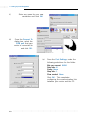
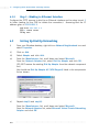
ii)
iii)
Enter any name for your new
connection and click OK.
From the Connect To
dialog box, select the
COM port that your
router is connected to
and click OK.
iv)
From the Port Settings, make the
following selections for the fields:
Bits per second: 9600
Data bits: 8
Parity: None
Stop bits: 1
Flow control: None
Click OK. This completes
configuring the communication link
between your router and the PC.
1-2
○
○
○
○
○
○
○
○
○
○
○
○
○
○
○
○
○
○
○
○
○
○
○
○
○
○
○
○
○
○
○
○
○
○
○
○
○
1 — Setting Up Local Management ○ ○ ○ ○ ○
v)
Power on the Power Mains and the switch on your router. You should see
similar messages as illustrated, on your HyperTerminal. (Actual messages vary
with different system and firmware version.)
This indicates successful serial link.
(If the messages did not display, power off your router and check the connection
of your serial cable. Make sure that the connection is firm and power on the
router again.)
You may now proceed with the following chapters to run local management.
○
○
○
○
○
○
○
○
○
○
○
○
○
○
○
○
○
○
○
○
○
○
○
○
○
○
○
○
○
○
○
○
○
○
○
○
○
1-3
2.
Basic Commands on Running Local
Management
This section gives you the basic guidelines on console commands, how to check your
router performances, router entries, to disconnect/connect your ADSL link and to
toggle between modes.
2.1
Guidelines
At the prompt for password, enter either 'stm' or 'password'
(without the quotes). These are factory default passwords.
(If you have changed the default password at the DSL Router
Commander - SNMP option, enter your new password.)
•
Type help to display on-line help on the console commands.
•
Type home to return to the initial command prompt.
•
Type . to repeat previous command.
•
Press ñ key on your keyboard to display previous command line
entered.
•
Type logout to logout. (You will be prompted for login again.)
•
Console commands are case-sensitive. Punctuations (e.g. '_' underscore,
'-' hyphen, ' ' spacing, etc) must be adhered to strictly.
•
For detailed description and syntax of console commands, you may refer
to Appendix A - Commonly Used Commands on this Technical Manual.
The commands in this manual are to be issued at initial command
prompt. You may also choose to go to the respective directories and
run the commands from there. (For example, to run bsp commands,
you need only to type channel at bsp> prompt to obtain the net data
rate.)
○
○
○
○
○
○
○
○
○
○
○
○
○
○
○
○
○
○
○
○
○
○
○
○
○
○
○
○
○
○
○
○
○
○
○
○
○
2-1
○ ○ ○ ○ ○ 2 — Basic Commands on Running Local Management
2.2
i)
Checking Your Router Performances
To check for line parameters:
bsp line
ii)
To check for line performance:
bsp perf
iii)
To check for line status:
bsp mode
iv)
To check net data rate:
bsp channel
v)
To monitor traffic:
bun list channels
2.3
Checking Your Router Entries
Messages displayed are the settings you have saved.
i)
To list existing interfaces:
ip device
or
bridge device
ii)
[for Transparent Bridge and RFC 2684 (RFC 1483) Ethernet Framing]
To list existing subnet mask:
ip subnet
or
ppp 1 lansubnet (for RFC 2364 and RFC 2516)
iii)
To list existing route table (not applicable for Transparent Bridge)
ip route
2-2
○
○
○
○
○
○
○
○
○
○
○
○
○
○
○
○
○
○
○
○
○
○
○
○
○
○
○
○
○
○
○
○
○
○
○
○
○
2 — Basic Commands on Running Local Management ○ ○ ○ ○ ○
2.4
To Disconnect/Connect the ADSL Link
i)
To disconnect the ADSL link:
bsp down
(Upon issuing this command, ADSL Link will be disconnected unless the
following command is issued.)
ii)
To re-connect (establish) the ADSL link:
bsp up
2.5
To Toggle between Various Modes
i)
To set router to multimode (auto-detect G.dmt, G.Lite & ANSI TI.413):
bsp multi
ii)
To force router into detecting G.Lite only:
bsp glite
iii)
To force router into detecting G.dmt only:
bsp gdmt
iv)
To force router into detecting ANSI T1.413 only:
bsp ansi
For commands in section 2.5, changes will take effect only after
you have re-established the line by issuing a bsp down and bsp up
commands (see section 2.4).
For changes to be permanent, please follow by a config save
command.
○
○
○
○
○
○
○
○
○
○
○
○
○
○
○
○
○
○
○
○
○
○
○
○
○
○
○
○
○
○
○
○
○
○
○
○
○
2-3
3.
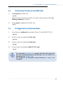
Configuring Your Router
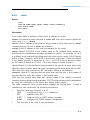
3.1
Configuration Flow Chart
Setup Your Serial Link
(Chapter 1)
Transparent
Bridge ?
Yes
No
(section 3.3.1)
Reset Router Configurations
(section 3.3.2)
Configure Your LAN settings
(section 3.3.3)
Configure Your WAN settings
RFC 2684
Ethernet
Framing
RFC 2684
IP Framing
RFC 2225
IPoA
RFC 2364
PPPoA
RFC 2516
PPPoE
Transparent
Bridge
[section 3.3.3, (i)]
[section 3.3.3, (ii)]
[section 3.3.3, (iii)]
[section 3.3.3, (iv)]
[section 3.3.3, (v)]
(Chapter 4)
Configure Routing Table
(section 3.3.4)
Enable IP Forwarding
(section 3.3.5)
NAT required ?
Enable NAT
Yes
(section 3.3.6)
No
Config Save
(section 3.3.7)
Configurations Completes!
○
○
○
○
○
○
○
○
○
○
○
○
○
○
○
○
○
○
○
○
○
○
○
○
○
○
○
○
○
○
○
○
○
○
○
○
○
3-1
○ ○ ○ ○ ○ 3 — Configuring Your Router
3.2
1.
All IP addresses and PVC values stated in this manual serve
only as examples for your better understanding. You are
required to replace these values with those given by your ADSL
Service Provider /System Administrator.
2.
Console commands are case-sensitive. Punctuations (examples,
'_' underscore, '-' hyphen, ' ' spacing, etc) must be adhered to
strictly.
3.
For detailed description and syntax of console commands, you may
refer to Appendix A - Commonly Used Commands on this
Technical Manual.
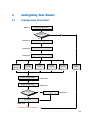
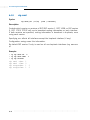
Network Setup Overview
This section gives an overview of a typical network. The addresses indicated are
used as examples throughout the whole manual. You are to replace them with
values given by your ADSL Service Provider / System Administrator.
WAN Gateway = 202.166.29.2
PC A
WAN IP
202.166.29.154
ADSL
Hub/Switch
PC B
Your Router
LAN IP
192.168.1.1 (with NAT)
202.166.30.1 (without NAT)
PVC=0/35
WAN
PC X
LAN
PCs with
Ethernet cards
(The Hub / Switch is optional if your router has more than 1 Ethernet Ports)
3-2
○
○
○
○
○
○
○
○
○
○
○
○
○
○
○
○
○
○
○
○
○
○
○
○
○
○
○
○
○
○
○
○
○
○
○
○
○
3 — Configuring Your Router ○ ○ ○ ○ ○
1.
For configuration without NAT:
The range of the IP address used in this example is from
202.166.30.1 to 202.166.30.6 as restricted by subnet mask defined.
Network ID : 202.166.30.0
Broadcast ID : 202.166.30.7
The ADSL Service Provider will have to create a static route:
Network ID : 202.166.30.0
Subnet Mask : ff:ff:ff:f8
Next Hop Gateway : 202.166.29.154
For PPPoA and PPPoE:
2.
The WAN IP and WAN Gateway will be dynamically assigned by the
PPP server. There is no need to specify the WAN IP nor to
configure a default route to the WAN Gateway.
Configuring the PCs:
For PC A:
(with NAT)
(without NAT)
IP
= 192.168.1.11
Subnet mask = 255.255.255.0
Gateway
= 192.168.1.1
= 202.166.30.2
= 255.255.255.248
= 202.166.30.1
For PC B:
(with NAT)
(without NAT)
IP
= 192.168.1.12
Subnet mask = 255.255.255.0
Gateway
= 192.168.1.1
= 202.166.30.3
= 255.255.255.248
= 202.166.30.1
For PC X:
(with NAT)
IP
= 192.168.1.23
Subnet mask = 255.255.255.0
Gateway
= 192.168.1.1
○
○
○
○
○
○
○
○
○
○
○
○
○
○
○
○
○
○
(without NAT)
= 202.166.30.6
= 255.255.255.248
= 202.166.30.1
○
○
○
○
○
○
○
○
○
○
○
○
○
○
○
○
○
○
○
3-3
○ ○ ○ ○ ○ 3 — Configuring Your Router
3.3
Configuring the Basics
Please carry out the following necessary steps to configure your router. Details of
each step can be found on the following pages.
Step 1: Resetting your Router's Configuration
Step 2: Configuring the LAN
Step 3: Configuring the WAN
Step 4: Configuring the Routing Table
Step 5: Enabling IP Forwarding
Step 6: Enabling NAT
Step 7: Saving the Configurations
With the basics configured, you may proceed also with the configurations on the
following sections.
3.4
3.5
3.6
Setting Up NAT Inbound Port Forwarding
Configuring DHCP Server
Configuring DNS Relay
3.7
3.8
3.9
Configuring SNMP
Setting Up Telnet Access
Configuring Autoloop for IP Interface
At the prompt for password, enter either 'stm' or 'password'
(without the quotes). These are factory default passwords.
(If you have changed the default password at the DSL Router
Commander - SNMP option, enter your new password.)
3-4
○
○
○
○
○
○
○
○
○
○
○
○
○
○
○
○
○
○
○
○
○
○
○
○
○
○
○
○
○
○
○
○
○
○
○
○
○
3 — Configuring Your Router ○ ○ ○ ○ ○
3.3.1
Configuring the Basics: Step 1 - Resetting your Router's
Configuration
Your router is set as Transparent Bridge by factory default.
Before starting a new configuration, always remember to clear all previous
configurations in your router.
To identify your current line protocol configured, type ip device.
Check the type and dev file listing to identify the protocol.
type
dev file
Line Protocol
ether
//bridge OR //edd
2684 (1483) Ethernet Framing*
Transparent Bridge*
ptp
//bun/port=atm/rfc1483...
2684 (1483) IP Framing
atm
//bun
2225 (1577) IPoA
ether
//ppp/DEVICE=1 mtu 1500
2364 PPPoA
ether
//ppp/DEVICE=1 mtu 1492
2516 PPPoE
* To further identify whether it is RFC 2684 (RFC 1483) Ethernet
Framing or Transparent Bridge, type ip route. For Transparent Bridge,
you will see 'Routing table empty' listed.
The following gives the commands to clear:
For PPPoA or PPPoE configurations, enter:
ppp 1 clear
For the rest of the configurations, follow the instructions below:
a) To delete all the interfaces:
(You may type ip device/bridge device to list existing interfaces.)
ip device flush
bridge device flush
○
○
○
○
○
○
○
○
○
○
○
○
○
○
○
○
○
○
○
○
○
○
○
○
○
○
○
○
○
○
○
○
○
○
○
○
○
3-5
○ ○ ○ ○ ○ 3 — Configuring Your Router
b) To delete all the subnet mask:
(You may type ip subnet to list existing subnet mask.)
ip subnet flush
c) To delete the route table, if any:
(You may type ip route to list existing routes.)
ip route flush
d) To remove NAT on a WAN interface, if any:
(See illustration shown below)
To list any existing NAT enabled WAN interface,
ip nat
If you have an existing NAT enabled WAN interface, you will see
nat add <wan_interface>
To remove the NAT enabled WAN interface,
ip nat delete <wan_interface>
<wan_interface>
3-6
○
○
○
○
○
○
○
○
○
○
○
○
○
○
○
○
○
○
○
○
○
○
○
○
○
○
○
○
○
○
○
○
○
○
○
○
○
3 — Configuring Your Router ○ ○ ○ ○ ○
3.3.2
Configuring the Basics: Step 2 - Configuring the LAN
Configure the LAN with IP address given by your System Administrator. Assuming
that the IP address given is 192.168.1.1:
ip device add lan ether //edd 192.168.1.1
ip subnet add lan.home . 192.168.1.1 ff:ff:ff:0
3.3.3
Configuring the Basics: Step 3 - Configuring the WAN
Configure the WAN with IP address given by your ADSL Service Provider. You may
configure your router to one of the following line protocols supported:
i)
RFC 2684 (RFC 1483) Ethernet Framing
ii)
iii)
iv)
RFC 2684 (RFC 1483) IP Framing
RFC 2225 (RFC 1577) IPoA
RFC 2364 PPPoA
v)
RFC 2516 PPPoE
i)
Configuring the WAN - For RFC 2684 (RFC 1483) Ethernet Framing
a) To add a bridge device, assuming the PVC given by your ADSL Service
Provider is 0/35:
For LLC-SNAP encapsulation:
bridge device add //bun/port=atm/rfc1483=true/mode=llcbridged/txvpi=0/
(all in one line)
txvci=35/rxvpi=0/rxvci=35
For VCMUX encapsulation:
bridge device add //bun/port=atm/rfc1483=true/mode=vcmuxbridged/
(all in one line)
txvpi=0/txvci=35/rxvpi=0/rxvci=35
For multiple PVCs, repeat the above commands with the different VPI and
VCI values.
b) To set the IP configuration of your WAN connection, assuming WAN IP
given by your ADSL Service Provider is fixed at 202.166.29.154:
ip device add wan ether //bridge 202.166.29.154
ip subnet add wan.home . 202.166.29.154 ff:ff:ff:0
OR
To obtain WAN settings automatically from your ADSL Service Provider:
ip device add wan ether //bridge dhcp
○
○
○
○
○
○
○
○
○
○
○
○
○
○
○
○
○
○
○
○
○
○
○
○
○
○
○
○
○
○
○
○
○
○
○
○
○
3-7
○ ○ ○ ○ ○ 3 — Configuring Your Router
ii)
Configuring the WAN - For RFC 2684 (RFC 1483) IP Framing
a) To set the IP configuration of your WAN connection, assuming the PVC
and WAN IP given by your ADSL Service Provider are 0/35 and
202.166.29.154 respectively:
For LLC-SNAP encapsulation:
ip device add wan ptp //bun/port=atm/rfc1483=true/mode=llcrouted/txvpi=0/txvci=35/
rxvpi= 0/rxvci=35 202.166.29.154 (all in one line)
ip subnet add wan.home . 202.166.29.154 ff:ff:ff:0
For VCMUX encapsulation:
ip device add wan ptp //bun/port=atm/rfc1483=true/mode=vcmuxrouted/
(all in one line)
txvpi=0/txvci=35/rxvpi=0/rxvci=35 202.166.29.154
ip subnet add wan.home . 202.166.29.154 ff:ff:ff:0
For multiple PVCs,
-
Repeat (a) with different PVCs values.
Append wan with an underscore ('_') followed by a unique digit for
each of the different PVC configured.
Issue a unique WAN IP for each of the different PVC configured
-
Examples:
append with a unique digit
For first PVC value (0/35)
ip device add wan_1 ptp //bun/port=atm/rfc1483=true/mode=llcrouted/
txvpi=0/txvci=35/rxvpi=0/rxvci=35 202.166.29.154
(all in one line)
ip subnet add wan_1.home . 202.166.29.154 ff:ff:ff:0
append with a unique digit
For second PVC value (0/100),
ip device add wan_2 ptp //bun/port=atm/rfc1483=true/mode=llcrouted/txvpi=0/txvci=100/
rxvpi=0/rxvci=100 202.166.29.155 (all in one line)
ip subnet add wan_2.home . 202.166.29.155 ff:ff:ff:0
unique WAN IP
3-8
○
○
○
○
○
○
○
○
○
○
○
○
○
○
○
○
○
○
○
○
○
○
○
○
○
○
○
○
○
○
○
○
○
○
○
○
○
3 — Configuring Your Router ○ ○ ○ ○ ○
iii)
Configuring the WAN - For RFC 2225 (RFC 1577) IPoA
a) To set the IP configuration of your WAN connection, assuming the WAN
IP given by your ADSL Service Provider is 202.166.29.154:
ip device add wan atm //atm 202.166.29.154
ip subnet add wan.home . 202.166.29.154 ff:ff:ff:0
b) To set the atm configuration, assuming the PVC and WAN Gateway given
by your ADSL Service Provider are 0/35 and 202.166.29.2 respectively:
ip ipatm pvc add wan atm 0/35 remoteip 202.166.29.2
OR
To obtain WAN settings automatically from your ADSL Service Provider:
ip device add wan atm //atm dhcp
ip ipatm pvc add wan atm 0/35 remoteip 202.166.29.2
For multiple PVCs,
- Repeat (b) with different PVCs values.
- Append wan with an underscore ('_') followed by a unique digit for
each of the different PVC configured.
- Issue a unique WAN IP for each of the different PVC configured
Examples:
unique WAN IP
For first PVC value (0/35)
ip ipatm pvc add wan_1 atm 0/35 remoteip 202.166.29.2
append with a unique digit
For second PVC value (0/100),
ip ipatm pvc add wan_2 atm 0/100 remoteip 202.166.29.3
○
○
○
○
○
○
○
○
○
○
○
○
○
○
○
○
○
○
○
○
○
○
○
○
○
○
○
○
○
○
○
○
○
○
○
○
○
3-9
○ ○ ○ ○ ○ 3 — Configuring Your Router
iv)
Configuring the WAN - For RFC 2364 PPPoA
a) To set the IP configuration of your WAN connection. The PPP module
supports multiple simultaneously connections, so we explicitly specify
Device 1 here. (This is required for PPP dial-out session):
ip device add ppp_device ether //ppp/DEVICE=1
b) To set the PPP channel configuration, assuming the PVC given by your
ADSL Service Provider is 0/35. CHAP authentication is used in this
example. Replace CHAP with PAP if you are using PAP authentication.
ADSL Service Provider will supply the myuserid and mypassword.
ppp
ppp
ppp
ppp
1
1
1
1
pvc 0 35 ip
welogin myuserid mypassword chap
gateway local
enable
c) To check the PPP connection every 10 seconds. (This is to allow the PPP
session to automatically re-establish itself after an ADSL link disruption
and re-connection.):
ppp 1 echo every 10
d) If you do not want to enable NAT, you may enable the PPP IP Unnumbered
feature (availability will depend on your router package). PPP IP
Unnumbered allows you to enable IP processing on a serial interface
without assigning it an explicit IP address. The ip unnumbered interface
can 'borrow' the IP address of another interface that is already configured
on the router, thereby conserving network and address space.
(Assuming your LAN Subnet mask is ff:ff:ff:f8.)
ppp 1 disable
ppp 1 unnumbered enable
ppp 1 lansubnet ff:ff:ff:f8
ppp 1 enable
config save
When the PPP link is established, you will notice that your LAN IP
address actually changes to the address of the WAN IP obtained from
the PPP Server. Your WAN IP address now becomes 0.0.0.1, a dummy
IP address.
To maintain IP connectivity to the router's LAN Port before and after
establishing the PPP unnumbered link, you are advised to pre-configure
the LAN IP to that of the given WAN IP. (You may refer to section 3.3.2,
Step 2 - Configuring the LAN.)
3-10
○
○
○
○
○
○
○
○
○
○
○
○
○
○
○
○
○
○
○
○
○
○
○
○
○
○
○
○
○
○
○
○
○
○
○
○
○
3 — Configuring Your Router ○ ○ ○ ○ ○
v)
Configuring the WAN - For RFC 2516 PPPoE
a) To set the IP configuration of your WAN connection. The PPP module
supports multiple simultaneously connections, so we explicitly specify
Device 1 here. The MTU (Maximum Transmit Unit) size for PPPoE must
also be specified as being 1492:
ip device add ppp_device ether //ppp/DEVICE=1 mtu 1492
b) To configure PPP device 1, assuming the PVC given by your ADSL Service
Provider is 0/35.
ppp 1 pppoe 0 35
c) CHAP authentication is used in this example. Replace CHAP with PAP
if you are using PAP authentication. ADSL Service Provider will supply
the myuserid and mypassword.
ppp 1 welogin myuserid mypassword chap
ppp 1 gateway local
ppp 1 enable
d) To check the PPP connection every 10 seconds. (This is to allow the PPP
session to automatically re-establish itself after an ADSL link disruption
and re-connection.):
ppp 1 echo every 10
e) If you do not want to enable NAT, you may enable the PPP IP Unnumbered
feature (availability will depend on your router package). PPP IP
Unnumbered allows you to enable IP processing on a serial interface
without assigning it an explicit IP address. The ip unnumbered interface
can 'borrow' the IP address of another interface that is already configured
on the router, thereby conserving network and address space.
(Assuming your LAN Subnet mask is ff:ff:ff:f8.)
ppp 1 disable
ppp 1 unnumbered enable
ppp 1 lansubnet ff:ff:ff:f8
ppp 1 enable
config save
When the PPP link is established, you will notice that your LAN IP address
actually changes to the address of the WAN IP obtained from the PPP
Server. Your WAN IP address now becomes 0.0.0.1, a dummy IP address.
To maintain IP connectivity to the router's LAN Port before and after
establishing the PPP unnumbered link, you are advised to pre-configure
the LAN IP to that of the given WAN IP. (You may refer to section 3.3.2,
Step 2 - Configuring the LAN.)
○
○
○
○
○
○
○
○
○
○
○
○
○
○
○
○
○
○
○
○
○
○
○
○
○
○
○
○
○
○
○
○
○
○
○
○
○
3-11
○ ○ ○ ○ ○ 3 — Configuring Your Router
3.3.4
Configuring the Basics: Step 4 - Configuring the Routing
Table
i)
Adding a Default route through a Gateway
(No default route is required for PPPoA and PPPoE line protocols.)
Assuming the WAN Gateway given by your ADSL Service Provider is 202.166.29.2:
ip route add default 0.0.0.0 202.166.29.2 0:0:0:0
ii)
Dynamic Routing
If dynamic routing is not required, it is recommended to disable this feature
to reduce unnecessary traffic:
ip rip accept all none
ip rip send all none
3.3.5
Configuring the Basics: Step 5 - Enabling IP Forwarding
To enable IP forwarding between your LAN and WAN,
ip relay all
3.3.6
Configuring the Basics: Step 6 - Enabling NAT
To enable NAT on a WAN interface,
i)
For RFC 2684 (RFC 1483) Ethernet Framing/1483 IP Framing/1577 IPoA
Assuming the WAN interface name is wan:
ip nat add wan
ii)
For RFC 2364 PPPoA / RFC 2516 PPPoE
ip nat add ppp_device
You may proceed to section 3.4 to set up your NAT Inbound Port Forwarding.
3.3.7
Configuring the Basics: Step 7 - Saving the Configurations
config save
3-12
○
○
○
○
○
○
○
○
○
○
○
○
○
○
○
○
○
○
○
○
○
○
○
○
○
○
○
○
○
○
○
○
○
○
○
○
○
3 — Configuring Your Router ○ ○ ○ ○ ○
3.4
Setting Up NAT Inbound Port Forwarding
(Port Address Translation)
When you have enabled NAT on the WAN interface, in order for people to reach your
HTTP (Web) Server, FTP Server and so on at your LAN, you need to activate the NAT
Inbound Port forwarding.
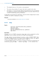
The following gives an illustration of a Web Server (IP=192.168.1.100) and FTP
Server (IP=192.168.1.101) connected to your router.
NAT Inbound Port Forwarding is not applicable for Transparent
Bridge configuration.
WAN Gateway = 202.166.29.2
PC A
WAN IP
202.166.29.154
ADSL
Hub/Switch
PC B
PCs with
Ethernet
cards
Your Router
LAN IP
192.168.1.1
PVC=0/35
WAN
LAN
Web Server
(The Hub / Switch is optional if your router
has more than 1 Ethernet Ports)
For PC A:
For Web Server:
IP
Subnet mask
Gateway
= 192.168.1.2
= 255.255.255.0
= 192.168.1.1
IP
Subnet mask
Gateway
For PC B:
○
○
○
○
= 192.168.1.100
= 255.255.255.0
= 192.168.1.1
For FTP Server:
IP
Subnet mask
Gateway
○
FTP Server
○
○
○
= 192.168.1.3
= 255.255.255.0
= 192.168.1.1
○
○
○
○
○
○
○
○
○
○
IP
Subnet mask
Gateway
○
○
○
○
○
○
○
○
○
○
○
= 192.168.1.101
= 255.255.255.0
= 192.168.1.1
○
○
○
○
○
○
○
○
3-13
○ ○ ○ ○ ○ 3 — Configuring Your Router
i)
To allow Web request to your HTTP (Web) Server (assuming the server is
using default TCP Port 80):
nat inbound add wan 80/tcp 192.168.1.100
ii)
To allow FTP request to your FTP Server (assuming the server is using default
TCP Port 21):
nat inbound add wan 21/tcp 192.168.1.101
iii)
To show the current IP forwarding rules:
nat inbound list
e.g.
iv)
#
Interface Port/Proto
New IP address
1
2
wan
wan
192.168.1.100
192.168.1.101
80/tcp
21/tcp
To remove a rule:
nat inbound delete 1
where 1 refers to the '#' corresponding to the interface you want to remove.
v)
To remove all rules:
nat inbound flush
You may refer to Appendix B - Well-Known TCP/UDP Ports for most
of the commonly used TCP/UDP Ports.
3-14
○
○
○
○
○
○
○
○
○
○
○
○
○
○
○
○
○
○
○
○
○
○
○
○
○
○
○
○
○
○
○
○
○
○
○
○
○
3 — Configuring Your Router ○ ○ ○ ○ ○
3.5
Configuring DHCP Server
The following DHCP configuration information may be used with any one of the line
protocols illustrated in Section 3.3.3, Step 3 - Configuring the WAN to produce a
complete system.
DHCP is not applicable to Transparent Bridge configuration.
3.5.1
Some useful commands for DHCP
i)
To list down the configuration file:
dhcpserver config
ii)
To delete the last command line:
dhcpserver config delete
iii)
To remove all previous configuration lines:
dhcpserver config flush
iv)
To show dhcpserver status:
dhcpserver status
v)
To allow changes to take effect immediately:
dhcpserver config confirm
dhcpserver reset
vi)
To save changes permanently:
config save
Any changes to the dhcpserver configurations must be followed by
dhcpserver config confirm, dhcpserver reset and config save.
○
○
○
○
○
○
○
○
○
○
○
○
○
○
○
○
○
○
○
○
○
○
○
○
○
○
○
○
○
○
○
○
○
○
○
○
○
3-15
○ ○ ○ ○ ○ 3 — Configuring Your Router
3.5.2
DHCP Server Illustration
All the PCs IP addresses, subnet mask and Gateway are obtained from your router
running the DHCP Server.
i)
For all PCs configuration:
From the Network Properties (right-click on Network Neighborhood / My
Network Places to select Properties) window of your Ethernet Card, set the
IP Address option at the TCP/IP Properties to 'Obtain an IP address
automatically' option.
ii)
Sample of DHCPSERVER Configurations:
dhcpserver
config add allow unknown-clients;
config add subnet 192.168.1.0 netmask 255.255.255.0
config add {
config add range 192.168.1.2 192.168.1.100;
config add option subnet-mask 255.255.255.0;
config add option routers 192.168.1.1;
config add option domain-name-servers IP 2,IP 2;
config add }
config confirm
iii)
For changes to take effect immediately:
dhcpserver reset
iv)
For permanent change:
config save
Upon typing config confirm, you should see messages similar to the one
shown below:
dhcpserver: Config changes confirmed, use “flashfs update” to
commit.
: Changes will not work correctly until restart - do this ASAP.
2
Replace with the LAN IP address of your router if you are using DNS relay. Else,
replace with the DNS provided by your ADSL Service Provider
3-16
○
○
○
○
○
○
○
○
○
○
○
○
○
○
○
○
○
○
○
○
○
○
○
○
○
○
○
○
○
○
○
○
○
○
○
○
○
3 — Configuring Your Router ○ ○ ○ ○ ○
3.6
Configuring DNS Relay
3.6.1
To Enable DNS Relay (with fixed IP address from your ADSL
Service Provider)
dnsrelay server IP 3
config save
restart
For RFC 2364 / RFC 2516:
To enable DNS Relay (with IP address obtained automatically from your
ADSL Service Provider), assuming the PPP module device is 1.
ppp 1 enableprimarydns relay
config save
restart
Ensure that the DNS Server address of the DHCP Server is set to the
LAN IP address of your router.
Example, (section 3.5.2 - DHCP Server Illustration, step ii.)
:
:
config add option domain-name-servers 192.168.1.1
:
(assuming the IP address of your router is 192.168.1.1.)
3.6.2
To Check DNS Relay Server Status
dnsrelay status
3.6.3
To Disable DNS Relay
dnsrelay config reset
3
○
Replace with the DNS provided by your ADSL Service Provider.
○
○
○
○
○
○
○
○
○
○
○
○
○
○
○
○
○
○
○
○
○
○
○
○
○
○
○
○
○
○
○
○
○
○
○
○
3-17
○ ○ ○ ○ ○ 3 — Configuring Your Router
3.7
Setting Up SNMP
3.7.1
Read/Write Access
The following illustrates the commands for write/read access.
i)
Add this command only when no IP has been assigned to the ether interface
of your router. The IP should have the same subnet as the Ethernet card and
must be unique in the network.:
ip device add lan ether //edd 192.168.1.1
ip subnet add lan.home . 192.168.1.1 ff:ff:ff:0
For example,
IP for Ethernet card : Dynamic IP obtained from far end server, range:
192.168.1.2 to 192.168.1.100
IP for router
ii)
: Fixed at 192.168.1.1
To enable SNMP read and write access:
ip snmp access write stm 4 192.168.1.11 5
(Assuming the IP address of the PC that you want to enable SNMP from is
192.168.1.11.)
OR
To enable SNMP read access:
ip snmp access read public 4 192.168.1.11 5
(Assuming the IP address of the PC that you want to enable SNMP from is
192.168.1.11.)
iii)
To save:
config save
restart
4
5
SNMP community names given by your System Administrator
Specifying this optional IP address will permit users to SNMP only from this specific
PC with the correct password.
3-18
○
○
○
○
○
○
○
○
○
○
○
○
○
○
○
○
○
○
○
○
○
○
○
○
○
○
○
○
○
○
○
○
○
○
○
○
○
3 — Configuring Your Router ○ ○ ○ ○ ○
3.7.2
SNMP Trap
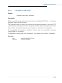
i)
To add a trap destination:
snmp trap add <community> <IP addr> [<port>]
ii)
To delete a trap destination:
snmp trap delete <community> <IP addr> [<port>]
iii)
To delete all traps destination:
snmp trap flush
iv)
To list trap(s) destination:
snmp trap list
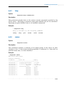
Example:
>snmp trap add community_name 192.168.1.5 21
>snmp trap list
trap add community_name 192.168.1.5 21
>snmp trap delete community_name 192.168.1.5 21
>snmp trap list
No trap destinations set
3.8
Setting up Telnet Access
(By factory default, Telnet Access is enabled. If the feature has been removed from
your router, you may carry out the following steps to enable it.)
Ensure that your router has SNMP write access enabled (see Section 3.7 - Setting
Up SNMP) before you proceed with the Telnet Access setup.
To enable Telnet to your router:
ip portname add telnet 23/tcp
config save
The Telnet password will be your SNMP write access community name
that you have entered during SNMP setup (section 3.7.1, step (ii)).
○
○
○
○
○
○
○
○
○
○
○
○
○
○
○
○
○
○
○
○
○
○
○
○
○
○
○
○
○
○
○
○
○
○
○
○
○
3-19
○ ○ ○ ○ ○ 3 — Configuring Your Router
3.9
Configuring Autoloop for IP Interface
ip device add loop loop 127.0.0.1
ip autoloop on
config save
By default, autoloop is disabled. Once the above commands are issued, you are able
to ping to your router's LAN IP.
3-20
○
○
○
○
○
○
○
○
○
○
○
○
○
○
○
○
○
○
○
○
○
○
○
○
○
○
○
○
○
○
○
○
○
○
○
○
○
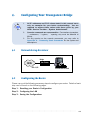
4.
Configuring Your Transparent Bridge
4.1
1.
All IP addresses and PVC values stated in this manual serve
only as examples for your better understanding. You are
required to replace these values with those given by your
ADSL Service Provider / System Administrator.
2.
Console commands are case-sensitive. Punctuations (examples,
'_' underscore, '-' hyphen, ' ' spacing, etc) must be adhered to
strictly.
3.
For any queries on the console commands, you may refer to
Appendix A - Commonly Used Commands for the syntax and
descriptions.
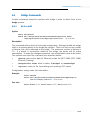
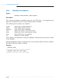
Network Setup Overview
Bridge
ADSL
Your Router
PVC=0/35
4.2
PC with Ethernet Card
Configuring the Basics
Please carry out the following necessary steps to configure your router. Details of each
step can be found on the following pages.
Step 1: Resetting your Router's Configuration
Step 2: Configuring the LAN
Step 3: Saving the Configurations
○
○
○
○
○
○
○
○
○
○
○
○
○
○
○
○
○
○
○
○
○
○
○
○
○
○
○
○
○
○
○
○
○
○
○
○
○
4-1
○ ○ ○ ○ ○ 4 — Configuring Your Transparent Bridge
Your router is set as Transparent Bridge by factory default. In
Transparent Bridge, only one of the PCs connected to your router
can have access to the Internet at any one time.
4.2.1
Step 1: Resetting your Router's Configuration
Before starting a new configuration for your router, always remember to clear all
previous configurations in your router. The following shows the commands and
explanations.
For PPPoA or PPPoE configurations, enter:
ppp 1 clear
For the rest of the configurations, follow the instructions below:
a) To delete all the interfaces:
(You may type ip device/bridge device to list existing interfaces.)
ip device flush
bridge device flush
b) To delete all the subnet mask:
(You may type ip subnet to list existing subnet mask.)
ip subnet flush
c) To delete the route table, if any:
(You may type ip route to list existing routes.)
ip route flush
d) To remove NAT on a WAN interface, if any:
(See illustration on the following page)
To list any existing NAT enabled WAN interface,
ip nat
If you have an existing NAT enabled WAN interface, you will see
nat add <wan_interface>
To remove the NAT enabled WAN interface,
ip nat delete <wan_interface>
4-2
○
○
○
○
○
○
○
○
○
○
○
○
○
○
○
○
○
○
○
○
○
○
○
○
○
○
○
○
○
○
○
○
○
○
○
○
○
4 — Configuring Your Transparent Bridge ○ ○ ○ ○ ○
<wan_interface>
4.2.2
Step 2: Configuring the LAN
i)
To add Ethernet device to the bridge:
bridge device add edd
ii)
To add a bridge device, assuming the PVC given by your ADSL Service Provider
is 0/35:
For LLC-SNAP encapsulation:
bridge device add //bun/port=atm/rfc1483=true/mode=llcbridged/txvpi=0/
txvci= 35/rxvpi=0/rxvci=35 (all in one line)
For VCMUX encapsulation:
bridge device add //bun/port=atm/rfc1483=true/mode=vcmuxbridged/txvpi=0/
txvci= 35/rxvpi=0/rxvci=35 (all in one line)
For multiple PVCs, repeat the above commands with the different VPI and
VCI values.
iii)
Set the IP address of your router ether port with the address given by your
System Administrator. (This is required in order to run the DSL Router
Commander.):
ip device add bridge ether //bridge 192.168.1.1
ip subnet add bridge.home . 192.168.1.1 ff:ff:ff:0
4.2.3
Step 3: Saving the Configurations
config save
○
○
○
○
○
○
○
○
○
○
○
○
○
○
○
○
○
○
○
○
○
○
○
○
○
○
○
○
○
○
○
○
○
○
○
○
○
4-3
5.
Router Configuration Examples
All IP addresses and PVC values stated in this manual serve only as
examples for your better understanding. You are required to replace
these values with those given by your ADSL Service Provider /
System Administrator.
For your better understanding, this section contains examples on configuring your
router. Do not duplicate these examples for your configuration. Check with your ADSL
Service Provider / System Administrator for actual IP addresses, PVC values and options
to use.
5.1
Example on RFC 2684 (RFC 1483) IP Framing
i)
To reset all IP configurations:
ppp 1 clear
ip device flush
bridge device flush
ip subnet flush
ip route flush
ii)
Configuring the LAN:
ip device add lan ether //edd 192.168.1.1
ip subnet add lan.home . 192.168.1.1 ff:ff:ff:0
iii)
Configuring the WAN (for LLC-SNAP encapsulation):
ip device add wan ptp //bun/port=atm/rfc1483=true/mode=llcrouted/
txvpi=0/txvci=35/rxvpi=0/rxvci=35 202.166.29.154 (all in one line)
ip subnet add wan.home . 202.166.29.154 ff:ff:ff:0
v)
Configuring the Routing Table:
ip route add default 0.0.0.0 202.166.29.2 0:0:0:0
vi)
To disable dynamic routing:
ip rip accept all none
ip rip send all none
○
○
○
○
○
○
○
○
○
○
○
○
○
○
○
○
○
○
○
○
○
○
○
○
○
○
○
○
○
○
○
○
○
○
○
○
○
5-1
○ ○ ○ ○ ○ 5 — Router Configuration Examples
vii)
Enabling IP Forwarding:
ip relay all
vii)
Enabling NAT:
ip nat add wan
viii)
Save configurations:
config save
5.2
Example on RFC 2364 PPPoA
i)
To reset all IP configurations:
ppp 1 clear
ip device flush
bridge device flush
ip subnet flush
ip route flush
ii)
Configuring the LAN:
ip device add lan ether //edd 192.168.1.1
ip subnet add lan.home . 192.168.1.1 ff:ff:ff:0
iii)
Configuring the WAN (for CHAP authentication):
ip device add ppp_device ether //ppp/DEVICE=1
ppp
ppp
ppp
ppp
iv)
1
1
1
1
pvc 0 35 ip
welogin myuserid mypassword chap
enable
echo every 10
To disable dynamic routing:
ip rip accept all none
ip rip send all none
v)
Enabling IP Forwarding:
ip relay all
vi)
Enabling NAT:
ip nat add ppp_device
vii)
Save configurations:
config save
5-2
○
○
○
○
○
○
○
○
○
○
○
○
○
○
○
○
○
○
○
○
○
○
○
○
○
○
○
○
○
○
○
○
○
○
○
○
○
6.
Configuring PPTP (Point-to-Point
Tunnelling Protocol)
1.
PPTP protocol is not supported in Windows® 95.
2.
Ensure that you have already setup your local management as
described in Chapter 1 - Setting Up Local Management.
3.
All IP addresses and PVC values stated in this manual serve
only as examples for your better understanding. You are
required to replace these values with those given by your
ADSL Service Provider / System Administrator.
4.
Console commands are case-sensitive. Punctuations (examples,
'_' underscore, '-' hyphen, ' ' spacing, etc) must be adhered to
strictly.
5.
For detailed description and syntax of console commands, you may
refer to Appendix A - Commonly Used Commands on this
Technical Manual.
6.1
Running the Console Commands
6.1.1
Step 1 - Configuring the LAN
Configure the LAN with IP address given by your System Administrator. Assuming
that the IP address given is 192.168.1.1:
ip device add lan ether //edd 192.168.1.1
ip subnet add lan.home . 192.168.1.1 ff:ff:ff:0
6.1.2
Step 2 - Configuring PPP Client and PNS (PPTP Network
Server)
Assuming the values for channel and tunnel given by your System Administrator are
2 and 1 respectively, and the PVC values given by your ADSL Service Provider are 0/
35:
ppp 2 pvc 0 35 ip
ppp 2 interface 0
ppp 2 tunnel 1
ppp 2 enable
○
○
○
○
○
○
○
○
○
○
○
○
○
○
○
○
○
○
○
○
○
○
○
○
○
○
○
○
○
○
○
○
○
○
○
○
○
6-1
○ ○ ○ ○ ○ 6 — Configuring PPTP (Point-to-Point Tunnelling Protocol)
6.1.3
Step 3 - Binding to Ethernet Interface
Configure the PPTP process to bind to an Ethernet interface and to setup tunnel 1
to listen (waiting for the PNS to initiate the connection). Assuming that the IP
address given is 192.168.1.1.
pptp bind 192.168.1.1
pptp 1 create listen
config save
6.2
Setting Up Dial-Up Networking
i)
From your Windows desktop, right-click on Network Neighborhood icon and
select Properties.
ii)
Click on Add.
iii)
Select Adapter and click Add.
iv)
From the Manufacturers list, scroll down and select Microsoft.
From the Network Adapters list, select Dial-Up Adapter and click OK.
(DO NOT remove the existing Dial-Up Adapter from the network component
list.)
You should see Dial-Up Adapter #2 (VPN Support) listed in the components
list as shown.
v)
Repeat step(ii) and step(iii).
From the Manufacturers list, scroll down and select Microsoft.
From the Network Adapters list, select Microsoft Virtual Private Networking
Adapter and click OK.
6-2
○
○
○
○
○
○
○
○
○
○
○
○
○
○
○
○
○
○
○
○
○
○
○
○
○
○
○
○
○
○
○
○
○
○
○
○
○
6 — Configuring PPTP (Point-to-Point Tunnelling Protocol) ○ ○ ○ ○ ○
You should see Microsoft
Virtual Private Networking
Adapter listed in the
components list as shown
on your left.
Click OK.
vi)
You may be prompted for your Windows 98 CD-ROM. Place the CD-ROM
into your CD-ROM Drive and follow the instructions prompted.
Restart your system when prompted.
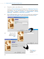
vii)
6.2.1
Creating Dial-Up Networking
i)
From your Windows desktop, right-click on Network Neighborhood icon and
select Properties.
ii)
Select Dial-Up Adapter#2 (VPN Support) and click Properties.
iii)
Click the Advanced tab.
At the Property field, select
IP Packet Size. Go to Value
field and select Medium from
the drop-down list.
iv)
○
Click OK. Restart your system.
○
○
○
○
○
○
○
○
○
○
○
○
○
○
○
○
○
○
○
○
○
○
○
○
○
○
○
○
○
○
○
○
○
○
○
○
6-3
○ ○ ○ ○ ○ 6 — Configuring PPTP (Point-to-Point Tunnelling Protocol)
v)
Proceed to create a new dial-up icon.
Locate your Dial-up Networking and double-click on Make New Connection.
(For example, if you are using Windows® 98, from your Windows desktop,
click on Start > Programs > Accessories > Communications > Dial-Up
Networking. Double-click on Make New Connection.)
vi)
At the following prompt, enter any name for the computer you are dialing to.
Select Microsoft VPN Adapter from the drop-down list and click Next.
vii)
Enter the LAN
address of your
Router and click
Next.
viii)
6-4
○
○
○
○
○
○
○
○
○
○
○
○
○
○
○
○
○
○
○
○
○
○
○
○
○
Click Finish to
complete the
process.
○
○
○
○
○
○
○
○
○
○
○
○
6 — Configuring PPTP (Point-to-Point Tunnelling Protocol) ○ ○ ○ ○ ○
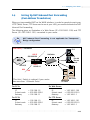
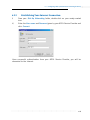
6.2.2
Establishing Your Internet Connection
i)
From your Dial-Up Networking folder, double-click on your newly-created
icon.
ii)
Enter the User name and Password given by your ADSL Service Provider and
click Connect.
Upon successful authentication from your ADSL Service Provider, you will be
connected to the Internet.
○
○
○
○
○
○
○
○
○
○
○
○
○
○
○
○
○
○
○
○
○
○
○
○
○
○
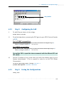
○
○
○
○
○
○
○
○
○
○
○
6-5
Appendix A - Commonly Used Commands
A.1
TCP/IP Commands
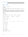
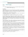
A.1.1
autoloop
Syntax:
autoloop [on|off]
Description:
Displays or sets the autoloop setting. Configuration saving saves this information.
By default autoloop is disabled.
The autoloop command is hidden, not shown by ip help.
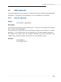
Example:
> ip autoloop
autoloop off
> ip device
#
type
dev file
device ether
ether
//nice
mtu 1500
device loop
loop
mtu 2048
> ip ping 127.0.0.1
ip: ping - reply received from 127.0.0.1
> ip ping 192.168.2.1
ip: ping - transmit error: Host is down (rc=62)
> ip autoloop on
> ip ping 192.168.2.1
ip: ping - reply received from 192.168.2.1
○
○
○
○
○
○
○
○
○
○
○
○
○
○
○
○
○
○
○
○
○
○
IP address
192.168.2.1
127.0.0.1
○
○
○
○
○
○
○
○
○
○
○
○
○
○
A-1
○ ○ ○ ○ ○ A- Commonly Used Commands
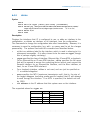
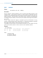
A.1.2
config
Syntax:
config [save]
Description:
Displays the IP configuration (not including the snmp configuration), or saves it in
flash memory.
The functionality of the config command is also accessible in the standard way
through the config process (e.g. config print ip), if that process is present. However,
when accessed through the config process, the snmp configuration is included.
Example:
> ip config
device add ether
device add vlane
ether
ether
subnet add vlane.home
subnet add ether.home
rip
rip
rip
rip
send
send
accept
accept
ether
vlane
ether
vlane
2
2
1
1
//nice
//lane
mtu 1500
mtu 1500
. 192.168.55.0
. 192.168.2.0
192.168.2.1
192.168.55.1
ff:ff:ff:00
ff:ff:ff:00
2
2
autoloop on
route add default
relay ether ether
relay ether vlane
relay vlane vlane
ipatm lifetime 60
# IP host table:
# Port table:
0.0.0.0
192.168.2.7
00:00:00:00
2
#
MAN
router 520/UDP
snmp
161/UDP
tftp
69/UDP
telnet 23/TCP
> ip config save
Updating flash filing system ...
done
ip: configuration saved
A-2
○
○
○
○
○
○
○
○
○
○
○
○
○
○
○
○
○
○
○
○
○
○
○
○
○
○
○
○
○
○
○
○
○
○
○
○
A- Commonly Used Commands ○ ○ ○ ○ ○
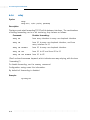
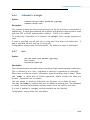
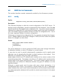
A.1.3
device
Syntax:
device
device add <i/f> <type> [<file>] [mtu <size>] [<IP address>]
device add wan ptp //bun/port=atm/rfc1483=true/mode=<encapsulation mode>/
txvpi=<vpi>/txvci=<vci>/rxvpi=<vpi>/rxvci=<vci> (all in one line)
device delete <i/f>
device flush
Description:
Displays the interfaces that IP is configured to use, or adds an interface to the
configuration, or deletes an interface, or all interfaces, from the configuration.
The commands to change the configuration take effect immediately. However, it is
necessary to save the configuration (e.g. with ip config save) to set the changes
permanently. The options used with this command are described below:
<i/f> is an arbitrary label for the interface, which is used in referring to it in
subsequent commands. (It is often chosen to be the same as <type>, though
this is perhaps slightly confusing.)
<type> specifies the class of interface: Ethernet-like, IP-over-ATM, or loopback.
For an Ethernet-like or IP-over-ATM interface, <file> specifies the file name
that will be opened to access the underlying device (which must support the
Emerald interface for an Ethernet-like interface, and the Blue interface, at
least, for an IP-over-ATM interface).
For a loopback interface, <file> is not used, and can just be specified as
- or omitted altogether.
<mtu> specifies the MTU (maximum transmission unit); that is, the size of
the largest datagram (excluding media-specific headers) that IP will attempt
to send through the interface. If no MTU is specified, the default unit will
be 1500.
<IP address> is the IP address that this system uses on the interface.
The supported values for <type> are
Class
Ethernet
<type>
ether
Applicable file(s)
//brid ge
IP Framing
IP -over-ATM
ptp
atm
//bun
/ /atm
Lo opback
loo p
-
//edd
○
○
○
○
○
○
○
○
○
○
○
○
○
○
○
○
○
○
○
○
○
○
○
○
○
○
○
○
○
○
○
○
○
○
○
○
A-3
○ ○ ○ ○ ○ A- Commonly Used Commands
Example:
ip device add wan ptp //bun/port=atm/rfc1483=true/mode=llcrouted/
(all in one line)
txvpi=0/txvci=35/rxvpi=0/rxvci=35 202.166.29.154
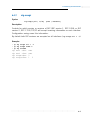
A.1.4
ip device
Syntax
ip device add <i/f> <type> <file> [mtu <size>] [<IP address>|dhcp]
ip device
Description
The ip device add command adds an interface to the configuration of the IP stack.
The last parameter of the command is normally the IP address of the interface. The
use of the string dhcp causes the IP address to be discovered by the DHCP client
software. Note that using the flag dhcp on an interface precludes running a DHCP
server on that interface!
The ip device command lists the current configuration of any devices attached to
the IP stack. A device configured to use DHCP will show dhcp in the IP address
column, followed by the actual IP address discovered and bound by DHCP, if any.
For interfaces configured to use DHCP, saving configuration only marks the interface
as using DHCP. It does not save the actual IP address discovered by DHCP, which
must be renewed.
A useful method of automatically configuring suitable IP devices is to put a device
add statement into the file //isfs/resolve and downloading it upon booting the image.
Example
> ip device add ethernet ether //edd dhcp
DHCP then discovers the IP address for the interface
> ip device
#
type
dev file
device ethernet ether
A-4
○
○
○
○
○
○
○
○
IP address
//edd mtu 1500dhcp
○
○
○
○
○
○
○
○
○
○
○
○
○
○
○
○
○
○
○
○
○
○
○
○
○
○
○
○
A- Commonly Used Commands ○ ○ ○ ○ ○
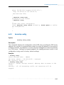
A.1.5
ipatm pvc
Syntax:
ipatm
ipatm
ipatm
ipatm
pvc
pvc add <i/f> [<port>] <vci>/[<IP address>][/<pcr>]
pvc delete <vci> [<port>]
pvc flush
Description:
Lists configured PVCs for use by IP-over-ATM; configures another; deletes one; or
deletes all.
<i/f> is the name of an interface configured for IP-over-ATM using PVCs.
<vci> is the VCI to use for the PVC. The range of possible VCIs depends on the
system.
<IP address> is the IP address of the machine at the other end of the PVC.
If it is not specified, TCP/IP will use Inverse ATMARP [RFC 2225 (RFC 1577)] to
determine the IP address; if it is specified, then Inverse ATMARP will not be used.
<pcr> is the peak cell rate, in cells per second. The default is 60000. (If neither
IP address nor PCR is specified, the / after the VCI can be omitted.)
<port> is the port name: it must be specified if the machine is a switch, and not
otherwise.
Configuration saving saves this information.
Example:
ip ipatm pvc add wan atm 0/35 remoteip 202.166.29.2
○
○
○
○
○
○
○
○
○
○
○
○
○
○
○
○
○
○
○
○
○
○
○
○
○
○
○
○
○
○
○
○
○
○
○
○
A-5
○ ○ ○ ○ ○ A- Commonly Used Commands
A.1.6
relay
Syntax:
relay
relay all | <i/f> [<i/f>] [forward]
Description:
Displays or sets what forwarding TCP/IP will do between interfaces. The combinations
of setting forwarding can be a bit confusing; they behave as follows:
Command:
Enables forwarding:
relay all
from every interface to every non-loopback interface
relay if1
from if1 to every non-loopback interface, and from
every interface to if1
relay if1 forward
from if1 to every non-loopback interface
relay if1 if2
from if1 to if2 and from if2 to if1
relay if1 if2 forward from if1 to if2
(Dont confuse the forward keyword, which indicates one-way relaying, with the term
forwarding!)
To disable forwarding, use the norelay command.
Configuration saving saves this information.
By default all forwarding is disabled.
Example:
ip relay all
A-6
○
○
○
○
○
○
○
○
○
○
○
○
○
○
○
○
○
○
○
○
○
○
○
○
○
○
○
○
○
○
○
○
○
○
○
○
A- Commonly Used Commands ○ ○ ○ ○ ○
A.1.7
rip accept
Syntax:
rip accept [all | <i/f>] [none | <version>]
Description:
Controls for which version or versions of RIP (RIP version 1, RFC 1058, or RIP
version 2, RFC 1723) TCP/IP will accept incoming information on each interface.
Configuration saving saves this information.
By default both RIP versions are accepted on all interfaces (rip accept all 1
2).
Example:
> ip rip accept all 1 2
> ip rip accept ether 2
> ip rip allowed
rip
rip
rip
rip
○
○
send ether
send vlane
accept ether
accept vlane
○
○
○
○
○
○
none
none
2
1 2
○
○
○
○
○
○
○
○
○
○
○
○
○
○
○
○
○
○
○
○
○
○
○
○
○
○
○
○
A-7
○ ○ ○ ○ ○ A- Commonly Used Commands
A.1.8
rip send
Syntax:
rip send [all | <i/f>] [none | <version>]
Description:
Controls which version or versions of RIP (RIP version 1, RFC 1058, or RIP version
2, RFC 1723) TCP/IP will use to broadcast routing information on each interface.
If both versions are specified, routing information is broadcast in duplicate, once
using each version.
Specifying all affects all interfaces except the loopback interface (if any).
Configuration saving saves this information.
By default RIP version 2 only is used on all non-loopback interfaces (rip send all
2).
Example:
> ip rip send all 2
> ip rip send ether 1
> ip rip allowed
rip send ether 1
rip send vlane 2
rip accept ether 1 2
rip accept vlane 1 2
A-8
○
○
○
○
○
○
○
○
○
○
○
○
○
○
○
○
○
○
○
○
○
○
○
○
○
○
○
○
○
○
○
○
○
○
○
○
A- Commonly Used Commands ○ ○ ○ ○ ○
A.1.9
route
Syntax:
route
route add <name> <dest> <relay> [<mask> [<cost> [<timeout>]]]
route delete <name>
route flush
Description:
Lists routes; adds or deletes a static route; or deletes all routes.
<name> is an arbitrary name specified to route add that can be used to delete the
route using route delete.
<dest> is the IP address of the network being routed to (only those bits of <dest>
corresponding to bits set in <mask> are relevant).
<relay> is the IP address of the next-hop gateway for the route.
<mask> (default ff:ff:ff:00) is the subnet mask of the network being routed to,
specified as four hexadecimal numbers separated by colons. For example, 0:0:0:0
is a default route (matches everything without a more specific route), ff:ff:ff:0 would
match a Class C network, and ff:ff:ff:ff is a route to a single host. (Note: the default
is not always sensible; in particular, if <dest> is 0.0.0.0 then it would be better
for the mask to default to 0:0:0:0. This may change in future versions.)
<cost> (default 1) is the number of hops counted as the cost of the route, which may
affect the choice of route when the route is competing with routes acquired from RIP.
(But note that using a mixture of RIP and static routing is not advised.)
<timeout> (default 0, meaning that the route does not time out) is the number of
seconds that the route will remain in the routing table.
Note that the routing table does not contain routes to the directly connected
networks, without going through a gateway. TCP/IP routes packets to such destinations
by using the information in the device and subnet tables instead.
The route command (with no parameters) displays the routing table. It adds a
comment to each route with the following information:
How the route was obtained; one of
MAN
configured by the route command
RIP
obtained from RIP
ICMP
obtained from an ICMP redirect message
SNMP configured by SNMP network management;
The time-out, if the route is not permanent;
○
○
○
○
○
○
○
○
○
○
○
○
○
○
○
○
○
○
○
○
○
○
○
○
○
○
○
○
○
○
○
○
○
○
○
○
A-9
○ ○ ○ ○ ○ A- Commonly Used Commands
The original time-out, if the route is not permanent;
The name of the interface (if known) that will be used for the route;
An asterisk (*) if the route was added recently and RIP has not yet processed
the change (the asterisk should disappear within 30 seconds, when RIP next
considers broadcasting routing information).
Configuration saving saves this information. (Only the routes configured by the route
command are saved or displayed by config .)
Example:
ip route add default 0.0.0.0 202.166.29.2 0:0:0:0
A.1.10
snmp
Syntax
snmp
snmp
snmp
snmp
snmp
access [read|write|delete|flush] <parameters>
config [save]
help [<cmd>|all]
trap [add|delete|flush|list] <parameters>
version
Description
Manages the list of SNMP community names (also used as passwords by other
applications, such as telnet) and the list of SNMP trap destinations.
The snmp version command displays the version number of ATMOS SNMP. Note,
the version number returned is the internal version number of Virata's code, not the
version of the SNMP protocol supported, which is SNMP v1.
In standard ATMOS systems, the console is configured to allow the commands to be
accessed by typing just snmp... instead of ip snmp... at the command line.
A-10
○
○
○
○
○
○
○
○
○
○
○
○
○
○
○
○
○
○
○
○
○
○
○
○
○
○
○
○
○
○
○
○
○
○
○
○
A- Commonly Used Commands ○ ○ ○ ○ ○
A.2
Bridge Commands
Console commands should be prefixed with bridge in order to direct them to the
bridge process.
A.2.1
device add
Syntax:
device add <device>
device add //bun/port=atm/rfc1483=true/mode=<encapsulation mode>/
txvpi=<vpi>/txvci=<vci>/rxvpi=<vpi>/rxvci=<vci> (all in one line)
Description:
This command adds a device to the bridge configuration. Attempts to add the bridge
itself or an existing device to the bridge are rejected. There is a limit on the number
of devices that can be attached to the bridge. The maximum number of devices is
10. If a device is successfully added to the bridge, the device will be active
immediately. To make the changes permanent, the configuration needs to be saved.
The options used with this command are described below:
•
<device> refers either edd (for Ethernet) or bun (for RFC 2684 (RFC 1483)
Ethernet) Framing)
•
<encapsulation mode> refers to either llcbridged or vcmuxbridged.
•
<vpi><vci> refers to the transmitting and receiving PVC values.
Configuration saving saves this information.
Example:
device add edd
device add //bun/port=atm/rfc1483=true/mode=llcbridged/txvpi=0/
txvci=35/rxvpi=0/rxvci=35 (all in one line)
See also:
○
○
○
○
device delete (A.2.2), device flush (A.2.3), device list (A.2.4)
○
○
○
○
○
○
○
○
○
○
○
○
○
○
○
○
○
○
○
○
○
○
○
○
○
○
○
○
○
○
○
○
A-11
○ ○ ○ ○ ○ A- Commonly Used Commands
A.2.2
device delete
Syntax:
device delete <device>
Description:
This command deletes a device from the bridge configuration. To make the changes
permanent, the configuration needs to be saved. The syntax of the device name is
the same as that for the device add command.
Configuration saving saves this information.
Example:
device delete //bun/port=atm/rfc1483=true/mode=llcbridged/txvpi=0/
txvci=35 /rxvpi=0/rxvci=35 (all in one line)
See also:
device add (A.2.1), device flush (A.2.3), device list (A.2.4)
A.2.3
device flush
Syntax:
device flush
Description:
This command removes all bridge devices that are currently attached to the bridge.
Example:
device flush
See also:
A-12
○
device add (A.2.1), device delete (A.2.2), device list (A.2.4)
○
○
○
○
○
○
○
○
○
○
○
○
○
○
○
○
○
○
○
○
○
○
○
○
○
○
○
○
○
○
○
○
○
○
○
A- Commonly Used Commands ○ ○ ○ ○ ○
A.2.4
device list
Syntax:
device list
Description:
This command lists all the devices that are currently attached to the bridge. It does
not show the stored configuration (which can be seen with the config print command).
Example:
device list
See also:
○
○
○
○
device add (A.2.1), device delete (A.2.2), device flush (A.2.3)
○
○
○
○
○
○
○
○
○
○
○
○
○
○
○
○
○
○
○
○
○
○
○
○
○
○
○
○
○
○
○
○
A-13
○ ○ ○ ○ ○ A- Commonly Used Commands
A.3
PPP Commands
Console commands should be prefixed with ppp in order to direct them to the ppp
process.
A.3.1
Console object types
The ppp process presents its setup in terms of a number of distinct object types:
The upper limit on the number of each of these objects permitted in a system is
configured using the config resource console command.
The current state of each object is saved by config save.
Channels
The ppp process provides a number of PPP connection channels. A channel is a
single PPP connection. Channels are numbered from 1. Many ppp console
commands affect only a single channel. The command is prefixed with the channel
number.
Users
A user is a user name and password. All users must have distinct names. The user
console command controls these.
A.3.2
Console examples
IP dial-out over PPP
To perform a dial-out over a PVC, operate as follows:
First set up a router device for PPP to use. No IP address should be specified, so
that the device is created but not enabled. The device name ppp_device should be
used.
ip device add ppp_device ether //ppp/DEVICE=1
ppp 1 pvc <whatever>
ppp 1 welogin <name> <password>
ppp 1 enable
If the configuration is saved at this point then the dial-in will be attempted
automatically when the system is reset.
A-14
○
○
○
○
○
○
○
○
○
○
○
○
○
○
○
○
○
○
○
○
○
○
○
○
○
○
○
○
○
○
○
○
○
○
○
○
A- Commonly Used Commands ○ ○ ○ ○ ○
A.3.3
<channel> echo every
Syntax:
<channel> echo every <seconds>
Description:
Echo is an LCP packet, which is used to test an established PPP link. It solicits a
ping-like reply from the far end.
This command sets a channel to confirm the continued presence of an open PPP
connection by sending an LCP echo every few seconds, and requiring an echo reply.
The number of seconds between echo requests is specified as a parameter.
If 0 is specified, the function is disabled. Use the info all command to read the
current state on a channel.
Configuration saving saves this information. By default, the function is disabled.
See also:
(manually initiated LCP echo)
(show current state)
echo
info all
○
○
○
○
○
○
○
○
○
○
○
○
○
○
○
○
○
○
○
○
○
○
○
○
○
○
○
○
○
○
○
○
○
○
○
○
A-15
○ ○ ○ ○ ○ A- Commonly Used Commands
A.3.4
<channel> pppoe
Syntax:
<channel> pppoe [[<port>] <vpi>] <vci> [ip] [acname "<string>"][servicename
"<string>"]<channel> pppoe none
Description:
Attach an ATM PVC to the given PPP channel using the PPPoE encapsulated driver
located on the lower layer. The port can be specified (only for a multi-port device),
and the VPI (default is 0), and the VCI. This is used for the configuration of a PPPoE
localized client only. No server support is offered.
The allowable range of port, VPI, VCI depends on the atm driver. Normal limits are
0 only for port, 0 only for VPI, 1..1023 for VCI.
If a single argument none is supplied, any current connection is torn down.
In the PPP state machine, providing a link of this form causes the link to be 'up'.
Note that a following enable must also be used, to allow the link to become
operational. This command initiates the PPPoE Discovery Phase, which is used to
detect compatible PPPoE Access Concentrators across the link. Once the discovery
Phase is complete, the use of the enable command will initiate LCP over the newly
connected link.
The ip indicates which form of data is transported over the connection. The ip is
assumed if not given. If the channel is not linked to an interface, and the channel
is for IP data, the channel is linked to interface 1.
The acname parameter specifies that a connection may be made with a specific
remote access concentrator. This name must exactly match the following parameter
string (enclosed in quotes). If the acname name does not match, a connection will
not be made to a responding non-matching access concentrator. If no acname is
given, the client will attach to any access concentrator that responds.
The servicename parameter specifies our client's servicename when "discovering" an
access concentrator. This parameter is for identification purpose only, when sending
packets to the remote. If no servicename is specified, no servicename tag will be
sent to the access concentrator.
It is possible for a PVC to become 'down' in the PPP state machine even though the
PVC is still there, for instance due to an authentication failure. If in this state, an
incoming packet will cause the PPP state machine to go 'up'.
Use the info command to read this information.
A-16
○
○
○
○
○
○
○
○
○
○
○
○
○
○
○
○
○
○
○
○
○
○
○
○
○
○
○
○
○
○
○
○
○
○
○
○
A- Commonly Used Commands ○ ○ ○ ○ ○
Configuration saving saves this information. By default a channel has no connection
information.
Example:
set channel 3 to be (VPI=3, VCI=32)
read PVC settings for channel 4
remove any PVC settings from channel 5
ppp 3 pppoe 3 32
ppp 4 info all
ppp 5 pppoe 0
○
○
○
○
○
○
○
○
○
○
○
○
○
○
○
○
○
○
○
○
○
○
○
○
○
○
○
○
○
○
○
○
○
○
○
○
A-17
○ ○ ○ ○ ○ A- Commonly Used Commands
A.3.5
<channel> pvc
Syntax:
<channel> pvc [[<port>] <vpi>] <vci> [ip|mac] [listen]
<channel> pvc none
Description:
Attach an ATM PVC to the given PPP channel. The port can be specified (only for
a multi-port device), and the VPI (default is 0), and the VCI.
The allowable range of port, VPI, VCI depends on the atm driver. Normal limits are
0 only for port, 0 only for VPI, 1..1023 for VCI.
If a single argument none is supplied, any current connection is torn down.
In the PPP state machine, providing a link of this form causes the link to be up.
Note that enable must also be used, to allow the link to become operational.
The ip or mac indicates which form of data is transported over the connection: one
of IP data (controlled by the IPCP protocol), or MAC data (for BCP). If neither is
provided, ip is assumed.
If the channel is not linked to an interface, and the channel is for IP data, the channel
is linked to interface 1. If the channel is not linked to an interface, and the channel
is for MAC data, the channel is linked to interface 2.
It is possible for a PVC to become down in the PPP state machine even though the
PVC is still there, for instance due to an authentication failure. If in this state, an
incoming packet will cause the PPP state machine to go up.
If listen is specified then this is the server end of a PVC. It will not send out PPP
Configure Requests until it first receives a packet over the PVC. When a connection
is torn down it goes returns to this state.
Use the info command to read this information.
Configuration saving saves this information. By default a channel has no connection
information.
Example:
set channel 3 to be (VPI=3, VCI=32)
read PVC settings for channel 4
remove any PVC settings from channel 5
ppp 3 pvc 3 32
ppp 4 pvc
ppp 5 pvc 0
A-18
○
○
○
○
○
○
○
○
○
○
○
○
○
○
○
○
○
○
○
○
○
○
○
○
○
○
○
○
○
○
○
○
○
○
○
○
A- Commonly Used Commands ○ ○ ○ ○ ○
A.3.6
<channel> welogin
Syntax:
<channel> welogin <name> <password> [pap|chap]
<channel> welogin none
Description:
This command describes how we should log in to the far end when a connection is
established. A name and password are supplied, and whether these should be used
with the PAP or CHAP authentication protocol. CHAP is the default.
To remove this information on a channel, call welogin with a single argument of
none.
If chap is specified, we will also log in using pap if the other end prefers this. If
pap is specified we will only log in using pap.
Configuration saving saves this information. By default no login is performed.
A.3.7
user
Syntax:
user add <name> [pwd <passwd> [pap|chap]]
user [<name>]
user delete <name>|all
Description:
This command stores information about a particular login name/password combination.
This is referred to as a user , regardless of whether it represents an individual.
When user is called on its own, information about all existing users is listed. When
user <name> is called with no further arguments, details of that user alone are
printed. Passwords are not shown.
Use user delete to delete an individual user by name, or to delete all users.
Use user add <name> to create a new user or update an existing one. The password
is stored, and the authentication protocol which must be used for this user.
If a user is deleted or changed, existing sessions are not affected.
Configuration saving saves this information.
○
○
○
○
○
○
○
○
○
○
○
○
○
○
○
○
○
○
○
○
○
○
○
○
○
○
○
○
○
○
○
○
○
○
○
○
A-19
○ ○ ○ ○ ○ A- Commonly Used Commands
A.4
NAT Commands
This section describes console commands provided by the nat process.
A.4.1
event
Syntax:
nat event [n]
Description:
This command displays or sets the current level of event tracing in the NAT process.
Larger values of n result in more verbose trace output, for example:
All trace messages are printed as background output, and therefore will not be
displayed asynchronously on the console unless the event show command has been
issued.
Example:
> nat event
Event level: 1
> nat event 2
A-20
○
○
○
○
○
○
○
○
○
○
○
○
○
○
○
○
○
○
○
○
○
○
○
○
○
○
○
○
○
○
○
○
○
○
○
○
A- Commonly Used Commands ○ ○ ○ ○ ○
A.4.2
inbound / Port Address Translation / Port Mapping
Syntax:
nat
nat
nat
nat
inbound
inbound
inbound
inbound
list
add <i/f> <port>/<proto> <new IP> [quiet]
delete <#>
flush
Description:
This command enables the user to list or to set up a series of rules, to determine
what happens to incoming traffic. By default all incoming packets, other that
packets arriving in response to outgoing traffic, will be rejected.
The nat inbound add command allows packets arriving on a specific port and IP
protocol to be forwarded to a machine on the private network. <i/f> is an interface
name as shown by the nat interface list command; <port> is the destination UDP
or TCP port number to match in the incoming traffic; <proto> is the IP protocol,
either udp or tcp; <new IP> is the new IP address on the private network which
the packets destination IP address should be translated to.
If a rule is added for an interface on which NAT is not enabled, the rule is added
anyway but a warning is printed to alert the user to this fact. quiet is a special option
which should not normally be issued at the console, and causes this warning to be
suppressed.
The quiet option is automatically added by NAT to when writing its configuration to
flash; this is because when a system boots, the NAT process reads in these rules
before IP has registered any interfaces.
nat inbound list shows the current rules for inbound traffic, including all the
arguments passed to the nat inbound add command.
nat inbound delete removes a rule, where <#> is the rule number as shown by the
nat inbound list command.
nat inbound flush removes all the rules.
Example:
>
>
#
1
2
>
○
○
○
○
nat inbound
nat inbound
Interface
ethernet
r1483
nat inbound
○
○
○
○
○
○
add ethernet 80/TCP 192.168.219.38
list
Port/Proto
New IP address
80/tcp
192.168.219.38
21/tcp
192.168.219.40
delete 2
○
○
○
○
○
○
○
○
○
○
○
○
○
○
○
○
○
○
○
○
○
○
○
○
○
○
A-21
○ ○ ○ ○ ○ A- Commonly Used Commands
A.4.3
info
Syntax:
nat info
Description:
This command displays the values of various parameters which are defined in the
module file, for example the session table size and the session timeouts. NATs
current memory usage is also displayed.
Example:
> nat info
Interface table size 1 (116 bytes)
Session table size per interface: 128 (6656 bytes)
Total: 6656 bytes
Hash table size per interface: 128 (512 bytes)
Total: 512 bytes
Fragment table size per interface: 32 (640 bytes)
Total: 640 bytes
Max queued buffers: 16
Fragment timeout:
30
Support for incoming fragments: enabled
Support for outgoing fragments: enabled
Session timeouts:
ICMP query:
10
UDP:
30
TCP (established):
300
TCP (other): 15
Initial port number: 10000
A-22
○
○
○
○
○
○
○
○
○
○
○
○
○
○
○
○
○
○
○
○
○
○
○
○
○
○
○
○
○
○
○
○
○
○
○
○
A- Commonly Used Commands ○ ○ ○ ○ ○
A.4.4
interfaces
Syntax:
nat interfaces
Description:
The nat interfaces command displays the IP router ports on which NAT is currently
enabled. For each of these, a status and IP address is listed. The IP address is
discovered automatically from the IP stack.
The status shows the user whether NAT is currently operational on that interface
(enabled), or whether NAT is still waiting to find out the interfaces IP address (not
ready).
Example:
> nat interfaces
Name
ethernet
ppp
A.4.5
Status
enabled
not ready
IP address
194.129.40.2
-
ip nat
Syntax:
ip nat add|delete <i/f name>
Description:
This command adds or removes NAT functionality from the named interface. The
interface name is the name as listed by the ip device command. NAT should always
be enabled only on the interface connecting to the public network, not the interface
connecting to the private network.
Example:
> ip nat add ethernet
See also:
○
○
○
○
event (A.4.2)
○
○
○
○
○
○
○
○
○
○
○
○
○
○
○
○
○
○
○
○
○
○
○
○
○
○
○
○
○
○
○
○
A-23
○ ○ ○ ○ ○ A- Commonly Used Commands
A.4.6
sessions
Syntax:
nat sessions <i/f> [all | summary]
Description:
The nat sessions command displays a list of currently active NAT sessions on the
interface <i/f>. In this context, a session is a pair of source IP addresses and port
numbers (and corresponding new port number) that NAT regards as one side of an
active connection. For each TCP or UDP session active, the source and destination
IP address and port number, and the local port number and the age of the session,
are printed.
The all option causes the sessions command to print out information on every
session, including sessions which have timed out. Normally the sessions command
only shows active sessions (those which have not timed out).
The summary command does not show detailed information on each session, but only
prints out the total number of active, timed out and available sessions.
Example:
> nat
Proto
TCP
TCP
sessions ppp
Age NAT port
34
1024
10
1025
Private address/port
192.168.219.38/3562
192.168.219.64/2135
Public address/port
194.129.50.6/21
185.45.30.30/80
Total:
2 sessions active
101 sessions timed out
126 sessions available
A-24
○
○
○
○
○
○
○
○
○
○
○
○
○
○
○
○
○
○
○
○
○
○
○
○
○
○
○
○
○
○
○
○
○
○
○
○
A- Commonly Used Commands ○ ○ ○ ○ ○
A.5
DHCP Server Commands
This section describes console commands provided by the dhcpser ver process.
A.5.1
config
Syntax:
dhcpserver config [add <text>|confirm|delete|flush]
Description:
This command displays or edits the current configuration of the DHCP server. To
display current configuration, provide no arguments to the command. Use of the add
argument adds the line <text> to the configuration file. Use of the confirm argument
reparses the configuration file, confirming the changes made if the parse is successful.
Use of the delete argument deletes the last line from the configuration file. Use of
the flush argument deletes the whole configuration.
Following any change to the configuration file, it is necessary to confirm the changes,
issue a flashfs update to commit the change to FLASH, and then restart the system
before the changes can take effect.
Subnet
subnet subnet-number netmask netmask {
[ parameters ]
[ declarations ]
}
The subnet statement is used to provide the DHCP server with enough information
to determine whether or not an IP address is on that subnet.
It may also be used to provide subnet-specific parameters and to specify what
addresses may be dynamically allocated to clients booting on that subnet. Such
addresses are specified using the range declaration.
subnet-number should be an IP address which resolves to the subnet number of the
subnet being described. The netmask should be an IP address which resolves to the
subnet mask of the subnet being described. The subnet number, together with the
subnet mask, are sufficient to determine whether any given IP address is on the
specified subnet.
Although a subnet mask must be given with every subnet declaration, it is
recommended that if there is any variance in subnet masks at a site, a subnet-mask
option statement be used in each subnet declaration to set the desired subnet mask;
any subnet-mask option statement will override the subnet mask declared in the subnet
statement.
○
○
○
○
○
○
○
○
○
○
○
○
○
○
○
○
○
○
○
○
○
○
○
○
○
○
○
○
○
○
○
○
○
○
○
○
A-25
○ ○ ○ ○ ○ A- Commonly Used Commands
Range
range [ dynamic-bootp ] low-address [ high-address ];
For any subnet on which addresses will be assigned dynamically, there must be at
least one range statement. The range statement gives the lowest and highest IP
addresses in a range. All IP addresses in the range should be in the subnet in which
the range statement is declared.
The dynamic-bootp flag may be specified if addresses in the specified range may be
dynamically assigned to BOOTP clients as well as DHCP clients. When specifying
a single address, high-address can be omitted.
Option statements
The DHCP server can supply values for all options given in RFC2132, including
those which the DHCP client cannot use for configuration (this is to allow option
support on, for example, Microsoft clients, which should support a much wider range
of configuration options). The available options are as follows:
option subnet-mask ip-address;
The subnet mask option specifies the clients subnet mask as per RFC 950. If no
subnet mask option is provided anywhere in scope, DHCP will use the subnet mask
from the subnet declaration for the network on which an address is being assigned.
However, any subnet-mask option declaration that is in scope for the address being
assigned will override the subnet mask specified in the subnet declaration.
option routers ip-address [, ip-address ... ];
The routers option specifies a list of IP addresses for routers on the clients subnet.
Routers should be listed in order of preference.
option domain-name-servers ip-address [, ip-address ... ];
The domain-name-servers option specifies a list of Domain Name System (STD 13,
RFC1035) name servers available to the client. Servers should be listed in order
of preference.
Example:
> dhcpserver config
Current DHCP server configuration
allow unknown-clients;
allow bootp;
A-26
○
○
○
○
○
○
○
○
○
○
○
○
○
○
○
○
○
○
○
○
○
○
○
○
○
○
○
○
○
○
○
○
○
○
○
○
A- Commonly Used Commands ○ ○ ○ ○ ○
subnet 192.168.219.0 netmask 255.255.255.0 {
range 192.168.219.10 192.168.219.30;
max-lease-time 5000;
}
> dhcpserver config flush
Configuration file flushed.
> dhcpserver config
—Current DHCP server configuration
(Issue dhcpserver config confirm followed by flashfs update to confirm
new configuration)
—>
A.5.2
dnsrelay config
Syntax:
dnsrelay config [reset]
Description:
This command displays the configuration of the DNS relay, including the DNS server
address, the number of communication retries the relay will attempt in the event of
a failed connection, and whether or not the relay has managed to connect successfully
to a DNS server. Adding the keyword reset to the config command results in the
configuration being reset to factor y default settings.
Example:
> dnsrelay config
Server discovery mode : MANUAL
DNS Server address : 192.168.96.200 - Connected
Max connection retries : 3
> dnsrelay config reset
dnsrelay : Default settings restored. (Warning: Must re-connect to DNS
server,
dnsrelay : all old outstanding traffic and connections will be
dropped).
○
○
○
○
○
○
○
○
○
○
○
○
○
○
○
○
○
○
○
○
○
○
○
○
○
○
○
○
○
○
○
○
○
○
○
○
A-27
○ ○ ○ ○ ○ A- Commonly Used Commands
A.5.3
dnsrelay retry
Syntax:
dnsrelay retry <retry value>
Description:
This command sets the maximum number of retries the DNS relay is allowed to
perform in the event of connection or transmission failure. The retry value must be
a number between 1 and 10.
Example:
> dnsrelay retry 4
Connection retry value set to 4.
>
A.5.4
dnsrelay server
Syntax:
dnsrelay server <DNS server IP address>
Description:
This command tells the DNS relay which DNS server to contact. Caution must be
exercised when using this command - if the DNS relay already knows which DNS
server to contact then all existing connections will be reset, all outstanding traffic
dropped, and the relay will then attempt to communicate with the newly appointed
DNS server.
Example:
> dnsrelay server 192.168.219.50
DNS server address set to 192.168.219.50.
>
A-28
○
○
○
○
○
○
○
○
○
○
○
○
○
○
○
○
○
○
○
○
○
○
○
○
○
○
○
○
○
○
○
○
○
○
○
○
A- Commonly Used Commands ○ ○ ○ ○ ○
A.5.5
dnsrelay status
Syntax:
dnsrelay status
Description:
This command displays the status of the DNS relay, including whether or not it
knows which DNS server to try to contact and, if so, whether or not it has
successfully connected to the server.
Example:
> dnsrelay status
DNS relay status
DNS server address discovery incomplete.
> dnsrelay server 192.168.219.50
DNS server address set to 192.168.219.50.
> dnsrelay status
DNS relay status
DNS server address : 192.168.219.50
Connection status : Connected
>
○
○
○
○
○
○
○
○
○
○
○
○
○
○
○
○
○
○
○
○
○
○
○
○
○
○
○
○
○
○
○
○
○
○
○
○
A-29
○ ○ ○ ○ ○ A- Commonly Used Commands
A.5.6
dnsrelay trace/untrace
Syntax:
dnsrelay <trace|untrace> [trace options]
Description:
This command enables or disables tracing for the DNS relay. If no arguments are
given the command lists the current tracing options enabled.
The following trace options are available:
socket
query
response
error
warn
conn
all
Report ALL socket-related I/O
Trace DNS resolver queries
Trace DNS server responses
Report all serious, error-evel events
Report all minor, warning-level events
Trace DNS server connectivity
Activate all trace options
Trace options are disabled by using the untrace command with the option names
to be disabled.
Saving configuration does not preserve the current tracing options that are enabled.
By default tracing of error is enabled.
Example:
> dnsrelay trace
No tracing options currently enabled.
> dnsrelay trace error warn query
Currently tracing: error warn query
A-30
○
○
○
○
○
○
○
○
○
○
○
○
○
○
○
○
○
○
○
○
○
○
○
○
○
○
○
○
○
○
○
○
○
○
○
○
A- Commonly Used Commands ○ ○ ○ ○ ○
A.5.7
help
Syntax:
dhcpserver help <command|all>
Description:
This command provides help on the various console commands provided by the
DHCP server. Specifying a command name gives detailed help on the command.
Specifying all gives detailed help on all available commands.
Example:
> dhcpserver help
Help is available on the following commands:
config
A.5.8
help
pool
status
trace
untrace
status
Syntax:
dhcpserver status
Description:
This command provides a summary of all leases known to the server on each
interface in turn. It also shows remaining available IP addresses (i.e. those with no
specified lease time, or client identifier).
Example:
> dhcpserver status
DHCP Server Lease Status
Interface “ethernet”
IP address
| Client UID
| Expiry
———————————————+—————————————————————————+—————————
192.168.219.1 | 01:00:20:af:20:6f:59 | 11 hours
192.168.219.2 | 01:00:20:af:11:2a:ac | 8 hours
192.168.219.3 |
Myclient | 140 seconds
192.168.219.4 | 00:20:af:20:00:2b
| 2 days
192.168.219.5 |
<unknown> | Never
192.168.219.6 |
<unknown> | Never
192.168.219.7 |
<unknown> | Never
192.168.219.8 |
<unknown> | Expired
192.168.219.9 |
<unknown> | Expired
192.168.219.10 |
Foobarbozzle | Expired
○
○
○
○
○
○
○
○
○
○
○
○
○
○
○
○
○
○
○
○
○
○
○
○
○
○
○
○
○
○
○
○
○
○
○
○
A-31
○ ○ ○ ○ ○ A- Commonly Used Commands
A.5.9
version
Syntax:
dhcpserver version
Description:
This command displays the current version number of the DHCP software.
Example:
> dhcpserver version
DHCP Version 1.02
>
A-32
○
○
○
○
○
○
○
○
○
○
○
○
○
○
○
○
○
○
○
○
○
○
○
○
○
○
○
○
○
○
○
○
○
○
○
○
A- Commonly Used Commands ○ ○ ○ ○ ○
A.6
BUN Commands
Command parsing is case insensitive. Whitespace may be used to separate distinct
arguments. Any prefix of the string bun to the command line is ignored.
A.6.1
bun list channels
Syntax:
list channels [<portname>]
Description:
List all open connections on the specified port. If no port is nominated, all channels
on all ports will be displayed.
The channels are shown with their identification number and a selection of useful
attributes. A full attribute list can be obtained via the show channel command.
All channels are shown with the Enabled attribute first, which indicates if the
channel has yet been enabled (connected) by the application code.
Example:
list channels 0
list channels atm:0
○
○
○
○
○
○
○
○
○
○
○
○
○
○
○
○
○
○
○
○
○
○
○
○
○
○
○
○
○
○
○
○
○
○
○
○
A-33
○ ○ ○ ○ ○ A- Commonly Used Commands
A.7
PPTP Commands
A.7.1
Console object types
The PPTP process provides a number of PPTP connection tunnels. A tunnel consists
of a control connection between the local PAC and a PNS, and a data connection
(known as a call) through which a number of PPP connections or channels may be
multiplexed.
The current state of each tunnel is saved by config save.
A.7.2
Console Examples
These examples are for configuration of the PPTP Access Concentrator (PAC).
Obviously the PPP client or server and the PNS must also be configured.
Dial-Out
The PPTP module uses functionality provided by the PPP module. Configure
PPP channel 2 for an outgoing PPTP connection, using PPTP tunnel 1, and
using PVC 800.
ppp
ppp
ppp
ppp
2
2
2
2
pvc 800
interface 0
tunnel 1 pptp out
enable
Next, configure the PPTP module to bind to an Ethernet interface with an IP
address of, for example 192.168.10.1, and set up tunnel 1 to listen (waiting
for the PNS to initiate the connection):
pptp bind 192.168.10.1
pptp 1 create listen
A-34
○
○
○
○
○
○
○
○
○
○
○
○
○
○
○
○
○
○
○
○
○
○
○
○
○
○
○
○
○
○
○
○
○
○
○
○
A- Commonly Used Commands ○ ○ ○ ○ ○
A.7.3
bind
Syntax
bind <ipaddress>|any|none
Description:
Specify which local interface to bind a listener to for incoming control connections.
If ipaddress is specified, PPTP will listen on port 1723 on that interface only for
incoming control connections. Typically this will be the IP address of the local side
network interface.
If any is specified, PPTP will accept control connections on any interface.
If none is specified, no incoming control connections will be accepted; in this case,
tunnels may only be established via the local create and connect commands.
Configuration saving saves this information. The default is none.
Example
To listen for incoming control connections on local interface 192.168.1.1 only, enter:
pptp bind 192.168.1.1
See also
<tunnel> create on section A.7.4, using the listen option.
An incoming connection can only be accepted if the listener has a free
tunnel object allocated to it. (Such objects are allocated with the <tunnel>
create listen command.) The tunnel object used will be freed for use
again when the tunnel is closed by either end.
○
○
○
○
○
○
○
○
○
○
○
○
○
○
○
○
○
○
○
○
○
○
○
○
○
○
○
○
○
○
○
○
○
○
○
○
A-35
○ ○ ○ ○ ○ A- Commonly Used Commands
A.7.4
<tunnel> create
Syntax
<tunnel> create <ipaddress>|listen
Description
Create a tunnel object.
If ipaddress is specified, the tunnel is associated with a remote PNS (PPTP Network
Server) at that IP address. The control connection is not actually established until
the use of tunnel is requested by PPP, or an explicit connect is issued.
If listen is specified, the tunnel is allocated for use by an incoming control connection
from a remote PNS. At least one such tunnel must exist if any incoming connections
are to be accepted at all.
Incoming connections are mapped to the first available listening tunnel object. It is
not currently possible to use properties of the incoming connection (such as its IP
address, or information supplied in the fields of the PPTP control messages) to map
the connection to a specific tunnel.
Configuration saving saves this information. By default, no tunnels are created.
Example
To connect Tunnel 1 to PNS at 192.168.1.2, enter:
ptp 1 create 192.168.1.2
A-36
○
○
○
○
○
○
○
○
○
○
○
○
○
○
○
○
○
○
○
○
○
○
○
○
○
○
○
○
○
○
○
○
○
○
○
○
A- Commonly Used Commands ○ ○ ○ ○ ○
A.7.5
<tunnel> delete
Syntax
<tunnel> delete
Description
Delete a tunnel object (the opposite of create). If the tunnel is currently connected,
any active data connections across the tunnel are terminated and the control
connection is closed.
Example
To delete PPTP Tunnel 1, enter:
pptp 1 delete
See also
<tunnel> create on section A.7.4 using the <ipaddress> option.
A.7.6
<tunnel> info
Syntax
<tunnel> info [all]
Description
Provide information about the current settings of this tunnel. This includes all
configured state, and also current protocol information.
Specifying all prints out more information.
info and status are synonyms.
A.7.7
list
Syntax
list
Description
Lists all currently created tunnel objects and the IP address of the remote PNS
associated with each one.
○
○
○
○
○
○
○
○
○
○
○
○
○
○
○
○
○
○
○
○
○
○
○
○
○
○
○
○
○
○
○
○
○
○
○
○
A-37
Appendix B - Well-Known TCP/UDP Ports
Service
Port Number/Port Type
File Transfer Protocol (FTP) Data
20/tcp
FTP Commands
21/tcp
Telnet
23/tcp
Simple Mail Transfer Protocol (SMTP) Email
25/tcp
Domain Name Server (DNS)
53/tcp and 53/udp
Trivial File Transfer Protocol (TFTP)
69/udp
finger
79/tcp
World Wide Web (HTTP)
80/tcp
POP3 Email
110/tcp
SUN Remote Procedure Call (RPC)
111/udp
Network News Transfer Protocol (NNTP)
119/tcp
Network Time Protocol (NTP)
123/tcp and 123/udp
News
144/tcp
Simple Management Network Protocol (SNMP)
161/udp
SNMP (traps)
162/udp
Border Gateway Protocol (BGP)
179/tcp
Secure HTTP (HTTPS)
443/tcp
rlogin
513/tcp
rexec
514/tcp
talk
517/tcp and 517/udp
ntalk
518/tcp and 518/udp
Open Windows
2000/tcp and 2000/udp
Network File System (NFS)
2049/tcp
X11
○
6000/tcp and 6000/udp
Routing Information Protocol (RIP)
520/udp
Layer 2 Tunnelling Protocol (L2TP)
1701/udp
○
○
○
○
○
○
○
○
○
○
○
○
○
○
○
○
○
○
○
○
○
○
○
○
○
○
○
○
○
○
○
○
○
○
○
B-1