1
E - Z CW
AUDIO FILTER
Ramsey Electronics Model No.
AF1
Here’s a quick and easy way to eliminate interfering CW
signals! This filter uses a digital bandpass filter to knock out
those unwanted signals. The adjustable center frequency and
switchable bandwidth add some versatility to this hard working
kit!
•
Utilizes “state of the art” switched capacitor bandpass filter IC’s !
•
Four selectable bandwidths - 750 Hz, 500 Hz, 250 Hz, and 100 Hz all with digital accuracy.
•
Adjustable filter center frequency for convenient listening.
•
Overload protected input accepts headphone or speaker level
audio.
•
“Smart” power input allows for AC or DC operation.
•
Audio bypass when unit is switched off - no need to disconnect
unit when not in use.
•
Speaker and headphone level outputs with adjustable volume. No
need for an external audio amp.
AF1 • 1
RAMSEY TRANSMITTER KITS
• FM100B Professional FM Stereo Transmitter
• FM25B Synthesized Stereo FM Transmitter
• MR6 Model Rocket Tracking Transmitter
• TV6 Television Transmitter
RAMSEY RECEIVER KITS
• FR1 FM Broadcast Receiver
• AR1 Aircraft Band Receiver
• SR2 Shortwave Receiver
• SC1 Shortwave Converter
RAMSEY HOBBY KITS
• SG7 Personal Speed Radar
• SS70A Speech Scrambler
• BS1 “Bullshooter” Digital Voice Storage Unit
• AVS10 Automatic Sequential Video Switcher
• WCT20 Cable Wizard Cable Tracer
• LABC1 Lead Acid Battery Charger
• LC1 Inductance-Capacitance Meter
RAMSEY AMATEUR RADIO KITS
• DDF1 Doppler Direction Finder
• HR Series HF All Mode Receivers
• QRP Series HF CW Transmitters
• CW7 CW Keyer
• CPO3 Code Practice Oscillator
• QRP Power Amplifiers
RAMSEY MINI-KITS
Many other kits are available for hobby, school, Scouts and just plain FUN. New
kits are always under development. Write or call for our free Ramsey catalog.
KIT NAME KIT INSTRUCTION MANUAL
Ramsey Electronics publication No. MAF1 Revision 1.1
First printing: October, 1994
COPYRIGHT 1994 by Ramsey Electronics, Inc. 590 Fishers Station Drive, Victor, New York
14564. All rights reserved. No portion of this publication may be copied or duplicated without the
written permission of Ramsey Electronics, Inc. Printed in the United States of America.
AF1 • 2
Ramsey Publication No. MAF1
Price $5.00
KIT ASSEMBLY
AND INSTRUCTION MANUAL FOR
AF1 CW
AUDIO FILTER
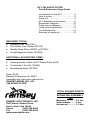
TABLE OF CONTENTS
Introduction to the AF1.................. 4
How it works.................................. 5
Parts list ........................................ 6
AF1 Assembly instructions............ 8
Schematic diagram ..................... 10
Parts Layout diagram .................. 11
Hook-up configurations ................ 13
Troubleshooting ........................... 14
Ramsey kit warranty .................... 15
RAMSEY ELECTRONICS, INC.
590 Fishers Station Drive
Victor, New York 14564
Phone (585) 924-4560
Fax (585) 924-4555
www.ramseykits.com
AF1 • 3
INTRODUCTION
Radio men know that the CW signal is the most reliable mode of
transmission when operating on the amateur radio bands. There are,
however, some inherent problems that exist in CW reception.
When listening to a carrier wave, or CW signal, our receiver is simply letting
us hear the difference between the local oscillator inside the radio and the
desired receive frequency. While this is the simplest form of reception (no
demodulation of the signal is required) it is also prone to receiving multiple
signals at one time making the desired carrier quite difficult to copy.
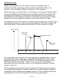
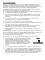
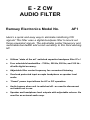
In an attempt to limit the number of carriers heard through the receiver one of
the easiest solutions is to filter the received audio to only allow a single CW
tone to be heard. That's where the Ramsey AF1 filter comes in to help.
AMPLITUDE
BANDPASS
FILTER
DESIRED SIGNAL
UNDESIRED
SIGNAL
250
0
500
750
1000
1250
1500
1750
FREQUENCY (Hz)
The audio filter board creates an audio frequency bandpass filter to remove
the undesired tones. It also has a selectable bandwidth (the width of the
bandpass filter) of 100, 250, 500, or 750 Hz. The center frequency of this
filter is also tunable from 400 - 1000 Hz, so you can tune the radio to
frequency that you would like to hear, not to whatever frequency the filter
wants to “listen to”.
When designing the new Ramsey SX series of HF frequency transceivers,
our engineers developed a superior audio filter using the latest in switched
capacitance filter technology integrated circuits. In fact, the filter performed
so well that our AF1 kit is a "spin-off" from the HF radio project.
AF1 • 4
THEORY OF OPERATION
Let’s have a look at what makes our audio filter so special. Have a look at the
schematic diagram and follow along.
First, having a look at the power supply section of the AF1 notice that diodes
D3, 6, 7,and 8 form a full wave bridge rectifier. We used this configuration so
that an AC or DC power source may be used for the unit (and the polarity
connection for a DC supply can be either way). This “raw” voltage is smoothed
by several large capacitors and routed to the voltage regulator IC to provide a
crystal clear source of DC voltage for the filter IC’s. You’ll also notice a few
bypass capacitors on the supply in case any of those nasty RF signals try to
get in and mess up the power supply.
At the heart of our kit is a pair of the MF8 switched capacitor bandpass filter
IC’s. Without these little marvels of technology this kit would not even exist!
Included on each chip is a pair of bandpass filters which can be cascaded to
provide sharper filter characteristics, a “Q LOGIC” binary input to set the filter
bandwidth, an adjustable internal oscillator to provide the center frequency for
our filter, and an extra op-amp to boot! Even the usually stingy data book
devotes 16 pages to the design possibilities for this hard working IC. The
overall bandwidth is controlled using switches S2 and S3 to provide a binary
input at the B, C, and D inputs of the MF8 IC. Resistors R12 and R13, along
with capacitor C8 provide the RC timing component necessary for the CMOS
oscillator.
The rest of the circuit is pretty straight forward - with whatever features could
be built in. The power switch doubles as an audio bypass, or feed through
when in the “OFF” position. Input protection diodes D1 and 2 limit the audio
input voltage to protect the valuable filter IC’s. Headphone jack J2 is set up to
accommodate either stereo or mono headsets, and headphone use will switch
the external speaker output off when the jack is inserted.
The headset / speaker output is from the LM380 audio amp IC. This chip
provides about 3 watts of noise free audio with a minimum of external
components.
AF1 • 5
AF1 PARTS LIST
Please check the boxes after the components have been identified, and now
is a good time to “sort” the like components into groups or bins (an egg
carton does nicely) to avoid using the wrong component during assembly.
RESISTORS AND POTENTIOMETERS
Please note that the kit contains some “special” 1 % tolerance resistors.
They can be easily identified by the fact that they contain an extra color
band, due to their more specific values. When identifying the resistors, first
we’ll sort the “normal” resistors, followed by the closer tolerance parts.
2
3
5
3
3
1
1
1
1
1
1
100 ohm resistors [brown-black-brown] (R21, 22)
1K ohm resistors [brown-black-red] (R19, 20, 23)
10K ohm resistors [brown-black-orange] (R10, 11, 15, 16, 17)
47K ohm resistors [yellow-violet-orange] (R1,3,8)
100K ohm resistors [brown-black-yellow] (R5,6,12)
750K ohm resistor [violet-green-yellow] (R2)
49.9K ohm resistor [yellow-white-white-red] (R7)
147K ohm resistor [brown-yellow-violet-orange] (R9)
294K ohm resistor [red-white-yellow-orange] (R4)
10K ohm PC mount potentiometer (R14)
100K ohm PC mount potentiometer (R13)
CAPACITORS
1
2
6
3
5
3
100 pF mica capacitor [marked 100 or 101] (C8)
.001 uF disc capacitor [marked .001 or 102] (C2, 5)
.01 uF disc capacitor [marked .01 or 103 or 10nF] (C10, 12, 14, 15,
16, 17)
.1 uF disc capacitor [marked .1 or 104] (C1, 4, 13)
10 uF electrolytic capacitors (C3, 6, 7, 19, 20)
1000 uF electrolytic capacitors (C9, 11, 18)
SEMICONDUCTORS AND INTEGRATED CIRCUITS
2
5
1
1
2
1
1N4148 diodes [glass case with black band] (D1, 2)
1N4002 diode [epoxy case marked 1N4002] (D3, 5, 6, 7, 8)
Light Emitting Diode [LED] (D4)
7808 voltage regulator [marked 7808] (VR1)
MF8 switched capacitance filter IC [16 pin DIP marked MF8] (U1, 2)
LM380 audio amplifier IC [14 pin DIP marked LM380N] (U3)
AF1 • 6
MISCELLANEOUS PARTS
1
2
3
1
1
2.5mm power jack (J4)
PC mount RCA jacks (J1, 3)
DPDT pushbutton switch (S1, 2, 3)
1/4” stereo headphone jack (J2)
AF1 printed circuit board
RAMSEY Learn-As-You-Build KIT ASSEMBLY
There are numerous solder connections on the AF1 printed circuit board.
Therefore, PLEASE take us seriously when we say that good soldering is
essential to the proper operation of your transmitter!
•
•
•
•
Use a 25-watt soldering pencil with a clean, sharp tip.
Use only rosin-core solder intended for electronics use.
Use bright lighting, a magnifying lamp or bench-style magnifier may
be helpful.
Do your work in stages, taking breaks to check your work. Carefully
brush away wire cuttings so they don't lodge between solder
connections.
We have a two-fold "strategy" for the order of the following kit assembly
steps. First, we install parts in physical relationship to each other, so there's
minimal chance of inserting wires into wrong holes. Second, whenever
possible, we install in an order that fits our "Learn-As-You Build" Kit building
philosophy. This entails describing the circuit that you are building, instead of
just blindly installing components. We hope that this will not only make
assembly of our kits easier, but help you to understand the circuit you’re
constructing.
For each part, our word "Install" always means these steps:
1. Pick the correct part value to start with.
2. Insert it into the correct PC board location.
3. Orient it correctly, follow the PC board drawing and the written
directions for all parts - especially when there's a right way
and a wrong way to solder it in. (Diode bands, electrolytic
capacitor polarity, transistor shapes, dotted or notched ends
of IC's, and so forth.)
4. Solder all connections unless directed otherwise. Use enough
heat and solder flow for clean, shiny, completed connections.
AF1 • 7
Now, let's get building!
Since you may appreciate some “warm-up” soldering practice as well as a
chance to put some “landmarks” on the PC board, we’ll first install some
“hardware” components. This will also help us to get acquainted with the up down, left - right orientation of the circuit board. Remember that the
components will be mounted on the “component” side of the circuit board
and soldered on the “solder” side of the circuit board.
1. Identify and install DPDT switch S3. Be sure to push the switch flat to
the circuit board. Solder all six connections.
2. In the same manner install DPDT toggle switches S1 and S2. Once
again, be sure to push the component flush to the circuit board before
soldering.
3. Install R14, the PC mount 10K ohm potentiometer. Solder all the
connections for secure, trouble free adjustment.
4. Install R13, the 100K ohm PC mount potentiometer.
5. Moving to the rear of the circuit board, install J1 and J3, the PC mount
RCA type. Solder all four connections securely.
6. Inspect the 1/4” headphone jack. Notice the seven pins protruding
from the bottom of the component. Be sure that none of these
connecting pins have been bent over before installing J2. Solder all
connections.
Next we’ll begin our “learn as you build” with the power supply section of the
circuit. Pay particular attention to the placement of the polarized components
as they can overheat (and even explode) if installed incorrectly.
7. Install J4, the 2.5 mm power jack.
8. Install C17, .01 uF disc capacitor [marked .01 or 103 or 10nF].
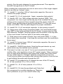
9. Install diode D8, 1N4002 type [marked 1N4002].
When installing a diode, pay careful attention to the
direction that the banded end faces. It must be
installed as shown in the parts diagram for proper
operation. Also, this component should be mounted
“standing up” with the component leads bent as
shown.
10. In the same manner, install diodes D7, 3, and 6, all 1N4002 type.
11. Install C18, 1000 uF electrolytic capacitor. Electrolytic capacitors are
polarized with a (+) and a (-) lead and must be installed in the correct
orientation. Ordinarily, only the negative side is marked on the capacitor
body with a dark band and the (-) sign clearly shown, while PC boards
will usually show the (+) hole location. Use care to ensure proper
AF1 • 8
polarity. See the parts diagram for proper placement. The capacitor
should fit snugly down to the PC board.
When installing the components be sure to save some of the longer clipped
leads to use later as “jumper” wires.
12. Install C11, another 1000 uF electrolytic capacitor. Be sure to
observe the proper polarity.
13. Install C19, 10 uF electrolytic. Again, remember that polarity!
14. Identify VR1, the 7808 voltage regulator [marked 7808]. This
component, too, has a right and wrong way to be installed. Be sure the
writing on the component faces inward toward the center of the PC
board. Using gentle pressure push the part about 1/4” from the circuit
board, and solder. See the parts diagram for proper installation.
15. Install C20, 10 uF electrolytic capacitor. Is that polarity correct?!
16. Using some of the scrap component leads, form and install jumper
wire JMP1 in the holes provided in the PC board. Jumper wires act like
little electronic “bridges” carrying signals from the bottom to the top side
of the circuit board, and then back to the bottom side again.
17. Grab some more scraps of leads, form and install JMP2, 3, 4. Hey,
this is better than recycling - if we keep this up there won’t be anything to
throw away!
18. Install C9, the last large 1000 uF electrolytic capacitor. Be sure to
observe the proper polarity.
19. Install D5, 1N4002 type diode. Note that the part stands up, and,
watch which way the banded end is pointed.
That wasn’t so bad, now was it! You’ve just completed the bridge
rectifier, filter, and regulation of your AF1 power supply. Take a moment
now to check parts placement and inspect the solder side of the board
for any solder opens or “bridges” between components or foil runs.
Touch up any solder connections that are less than perfect. Now its time
to get building the audio path through the AF1.
20. Install C16 (its adjacent to J3 towards the rear of the PC board),
.01 uF disc [marked .01 or 103 or 10nF].
21. Install C15, .01 uF disc [marked .01 or 103 or
10nF].
22. Install R19, 1K ohm [brown-black-red]. Note that
this component is mounted standing up. Resistors
aren’t polarized, so you can install it either way.
AF1 • 9
23. Install R22 and R21, both 100 ohm [brown-black-brown]. They are
also mounted standing up.
24. Install stand up resistor R20, 1K ohm [brown-black-red].
25. Form and install diode D1, a 1N4148 type small signal diode [small
glass case with black band]. Be sure to orient the part as shown in the
parts placement diagram.
26. In the same manner, install diode D2, another 1N4148. Note that the
polarity of this diode is reversed.
27. Install C4, .1 uF disc capacitor [marked .1 or 104].
28. Install R8, 47K ohm [yellow-violet-orange]. Remember to stand up
the component.
29. Install C5, .001 uF disc capacitor [marked .001 or 102].
30. Form and install R9, 147K ohm [brown-yellow-violet-orange]. Figured
out that 4 band code yet? The colors are the same value, just one more
in the sequence i.e. brown (1)-yellow (4)-violet (7)-orange (000) = 147K !
AF1 • 10
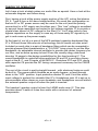
AF1 PARTS LAYOUT DIAGRAM
AF1 • 11
31. Using a scrap component lead, form and install JMP11.
32. Install C13, .1 uF disc [marked .1 or 104].
33. Install C2, .001 uF disc capacitor [marked 102 or .001].
34. Install R1, 47K ohm [yellow-violet-orange]. I’ll bet you didn’t forget to
stand it up.
35. Install C10, .01 uF disc capacitor [marked .01 or 103 or 10nF].
36. Install C12, .01 uF disc cap (that's snazzy electronics lingo for
capacitor). Again, its marked .01 or 103 or 10nF.
Seems like we put this off forever, but it is now time to install the LM380
audio amplifier IC. Be advised that an IC socket IS NOT advisable in this
application as the large copper trace acts as a heat “sink” for the IC. This
prevents the chip from overheating when in use.
37. Now that you’re all warmed up with your soldering iron (pun
intended), install the LM380 14 pin IC. Notice that one end of the chip is
marked with a dot, notch, or band. Be sure to orient this end as shown in
the parts diagram.
38. Install C1, .1 uF disc capacitor [marked .1 or 104].
39. Install R6, 100K ohm [ brown-black-yellow].
40. Install C6, 10 uF electrolytic. Check polarity when installing this part.
41. Using some more of your scrap component leads, form and install
JMP5, 6, 7, 8, and 9. Circuit board space gets pretty tight underneath the
MF8 IC’s so a few jumpers are needed to complete the necessary
connections to the chip.
42. Install C3, 10 uF electrolytic. Did you check the orientation?
43. Install C8, 100 pF mica type disc cap [marked 100 or 101].
44. Install R12, 100K ohm [brown-black-yellow].
45. Install R4, 294K ohm [red-white-yellow-orange]. It is mounted lying
down - I sure hope it doesn’t fall asleep on the job!
46. Install R16, 15, and 11; all 10K ohm stand up resistors [brown-blackorange].
47. Install C7, 10 uF electrolytic capacitor. Check the polarity.
48. Install R10, 10K ohm [brown-black-orange].
49. Form and install JMP10, the last jumper wire.
50. Install R17, 10K ohm [brown-black-orange]. Notice that I’m not
reminding you to stand it up anymore.
AF1 • 12
51. Install R3, 47K ohm [yellow-violet-orange].
52. Install R2, 750K ohm [violet-green-yellow].
53. Install R5, 100K ohm [brown-black-yellow].
54. Install R7, 49.9K ohm [yellow-white-white-red].
55. Install C14, .01 uF disc capacitor [marked .01 or 103 or 10nF].
56. Now we’ll install the two MF8 switched capacitance bandpass filter
IC’s. If you prefer to use an IC socket, you may install one if you wish.
Be aware, however, that our techies find more repair problems due to
sockets than due to chips burned out from overheating with a soldering
iron. Be extra careful not to “bridge” the printed circuit traces together.
Notice that one end of the chip is marked with a dot, notch, or band. Be
sure to orient this end as shown in the parts diagram.
57. Install R23, 1K ohm [brown-black-red]. It mounts
standing up.
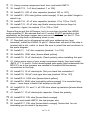
57. Lastly, we have to wire the power “on” indicator
LED. LED’s are polarized, so be sure to orient the long
lead as shown in the diagram. The leads will slide
through the holes on the top of the switch contacts. Be
sure to leave enough lead length on the diode so it can
“poke through” the front panel.
Long
Lead
CONGRATULATIONS
You have just completed your AF1 CW audio filter unit. Take a well
deserved break now. Give your eyes a rest. When you return, be sure to
check over your work on the
entire circuit board. Energizing the circuit board with solder “bridges” or
misplaced components can damage your kit. Five minutes well spent now
can save hours of troubleshooting time and dollars in expensive replacement
components.
SETUP AND OPERATIION OF THE AUDIO FILTER
We know that your itching to use your audio filter, so here are the testing
instructions to verify the operation of your filter.
Connect a suitable power supply (12-14 V AC or DC) to the power jack.
Connect an audio source (an audio function generator does nicely, but
you may use the actual rig you’re going to connect your filter to, provided
you are capable of receiving a 400 - 1000 Hz tone).
AF1 • 13
Connect an audio output device such as a speaker or headset to the
appropriate jack (J1 or J2, respectively). With switch S1 in the off
position you should be able to hear the tone under test.
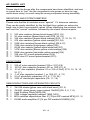
Set switches S2 and S3 in the “out” position for maximum bandwidth.
Push in switch S1 to energize the circuit.
Bandwidth S2
S3
Adjust R14 for the proper volume level.
(Hz)
You can now experiment with your kit by
100
IN
IN
changing the tone frequencies with the audio
generator and following with the center
250
IN
OUT
frequency adjustment of the AF1.
By changing the position of switches S2 and
S3 you can change the bandwidth of the audio
filter. The chart describes the switch/bandwidth
for the AF1.
500
OUT
IN
750
OUT OUT
You should be able to “hear” the differences in the bandpass filters. Try and
plot a few data points for frequency vs loudness and you should be able to
plot the different bandwidths. This is by no means an exact measurement but
it is impressive that this digitally controlled switched capacitance filter is
responding to your commands -and - you did it yourself!
TROUBLESHOOTING INSTRUCTIONS
While we had hoped that it wouldn’t come to this, if you’re having trouble with
your kit here are a few suggestions. Use a methodical trouble shooting
technique - a clear head and a voltmeter are all that are usually required to
correct any problem. Rest assured that both of the MF8 IC’s have been pretested before they were included in your kit. More times than not a part in
the wrong place causes the problem, so ask a friend to check your work as
well. Try not to be discouraged, working backwards through the assembly
steps will usually lead you to the problem.
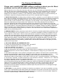
CONCLUSION
We sincerely hope that you have enjoyed the construction and use of this
Ramsey Kit. As always, we have tried to compose our manual in the easiest,
most “user friendly” format that is possible. As our customers, we value your
opinions, comments, and additions that you would like to see in future
publications. Please submit comments or ideas to:
Ramsey Electronics Inc.
Attn. Hobby Kit Department
590 Fishers Station Drive
Victor, NY 14564
And once again, thanks from the folks at Ramsey!
AF1 • 14
The Ramsey Kit Warranty
Please read carefully BEFORE calling or writing in about your kit. Most
problems can be solved without contacting the factory.
Notice that this is not a "fine print" warranty. We want you to understand your rights and ours too! All
Ramsey kits will work if assembled properly. The very fact that your kit includes this new manual is
your assurance that a team of knowledgeable people have field-tested several "copies" of this kit
straight from the Ramsey Inventory. If you need help, please read through your manual carefully, all
information required to properly build and test your kit is contained within the pages!
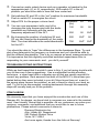
1. DEFECTIVE PARTS: It's always easy to blame a part for a problem in your kit, Before you conclude
that a part may be bad, thoroughly check your work. Today's semiconductors and passive components
have reached incredibly high reliability levels, and it’s sad to say that our human construction skills
have not! But on rare occasions a sour component can slip through. All our kit parts carry the Ramsey
Electronics Warranty that they are free from defects for a full ninety (90) days from the date of
purchase. Defective parts will be replaced promptly at our expense. If you suspect any part to be
defective, please mail it to our factory for testing and replacement. Please send only the defective part
(s), not the entire kit. The part(s) MUST be returned to us in suitable condition for testing. Please be
aware that testing can usually determine if the part was truly defective or damaged by assembly or
usage. Don't be afraid of telling us that you 'blew-it', we're all human and in most cases, replacement
parts are very reasonably priced.
2. MISSING PARTS: Before assuming a part value is incorrect, check the parts listing carefully to see
if it is a critical value such as a specific coil or IC, or whether a RANGE of values is suitable (such as
"100 to 500 uF"). Often times, common sense will solve a mysterious missing part problem. If you're
missing five 10K ohm resistors and received five extra 1K resistors, you can pretty much be assured
that the '1K ohm' resistors are actually the 'missing' 10 K parts ("Hum-m-m, I guess the 'red' band
really does look orange!") Ramsey Electronics project kits are packed with pride in the USA. If you
believe we packed an incorrect part or omitted a part clearly indicated in your assembly manual as
supplied with the basic kit by Ramsey, please write or call us with information on the part you need
and proof of kit purchase.
3. FACTORY REPAIR OF ASSEMBLED KITS:
To qualify for Ramsey Electronics factory repair, kits MUST:
1. NOT be assembled with acid core solder or flux.
2. NOT be modified in any manner.
3. BE returned in fully-assembled form, not partially assembled.
4. BE accompanied by the proper repair fee. No repair will be undertaken until we have received the
MINIMUM repair fee (1/2 hour labor) of $25.00, or authorization to charge it to your credit card
account.
5. INCLUDE a description of the problem and legible return address. DO NOT send a separate letter;
include all correspondence with the unit. Please do not include your own hardware such as
nonRamsey cabinets, knobs, cables, external battery packs and the like. Ramsey Electronics, Inc.,
reserves the right to refuse repair on ANY item in which we find excessive problems or damage due
to construction methods. To assist customers in such situations, Ramsey Electronics, Inc., reserves
the right to solve their needs on a case-by-case basis.
The repair is $50.00 per hour, regardless of the cost of the kit. Please understand that our technicians
are not volunteers and that set-up, testing, diagnosis, repair and repacking and paperwork can take
nearly an hour of paid employee time on even a simple kit. Of course, if we find that a part was
defective in manufacture, there will be no charge to repair your kit (But please realize that our
technicians know the difference between a defective part and parts burned out or damaged through
improper use or assembly).
4. REFUNDS: You are given ten (10) days to examine our products. If you are not satisfied, you may
return your unassembled kit with all the parts and instructions and proof of purchase to the factory for
a full refund. The return package should be packed securely. Insurance is recommended. Please do
not cause needless delays, read all information carefully.
AF1 • 15
AF1 CW AUDIO FILTER
Quick Reference Page Guide
Introduction to the AF1 .................. 4
How it works .................................. 5
Parts list ......................................... 6
AF1 Assembly instructions ............ 8
Schematic diagram ...................... 10
Parts Layout diagram................... 11
Hook-up configurations .................13
Troubleshooting ............................14
Ramsey kit warranty .....................15
REQUIRED TOOLS
• Soldering Iron (WLC100)
• Thin Rosin Core Solder (RTS12)
• Needle Nose Pliers (MPP4 or RTS05)
• Small Diagonal Cutters (RTS04)
ADDITIONAL SUGGESTED ITEMS
•
•
•
Helping Hands Holder for PC Board/Parts (HH3)
Technician’s Tool Kit (TK405)
Desoldering Braid (RTS08)
Price: $5.00
Ramsey Publication No. MAF1
Assembly and Instruction manual for:
RAMSEY MODEL NO. AF1
CW AUDIO FILTER
RAMSEY ELECTRONICS, INC.
590 Fishers Station Drive
Victor, New York 14564
Phone
(585) 924-4560
Fax
(585) 924-4555
www.ramseykits.com
TOTAL SOLDER POINTS
114
ESTIMATED ASSEMBLY
TIME
Beginner .............. 3.5 hrs
Intermediate ........ 2 hrs
Advanced ............. 1.5 hrs
AF1 • 16