1
SH-201_r_e.book 1 ページ 2006年4月27日 木曜日 午前11時28分
Owner’s Manual
Thank you, and congratulations on your choice of the Roland SH-201.
Before using this unit, carefully read the sections entitled: “USING THE UNIT SAFELY”
(p. 8) and “IMPORTANT NOTES” (p. 10). These sections provide important information
concerning the proper operation of the unit. Additionally, in order to feel assured that
you have gained a good grasp of every feature provided by your new unit, Owner’s
manual should be read in its entirety. The manual should be saved and kept on hand as a
convenient reference.
To learn about the performance functions...
Playing sounds ...............................................................................p. 16
To create your own sounds...
Creating sounds .............................................................................p. 27
Parameter list..................................................................................p. 60
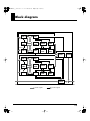
Block diagram ................................................................................p. 75
To learn how the knobs and buttons work...
Panel descriptions............................................................................p. 2
Panel index .....................................................................................p. 76
Contents ............................................................................................p. 4
Index ................................................................................................p. 78
220
* All product names mentioned in this document are trademarks or registered trademarks of their respective owners.
202
Copyright © 2006 ROLAND CORPORATION
All rights reserved. No part of this publication may be reproduced in any form without the
written permission of ROLAND CORPORATION.
SH-201_r_e.book 2 ページ 2006年4月27日 木曜日 午前11時28分
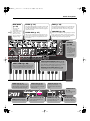
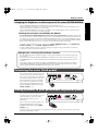
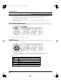
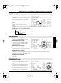
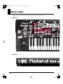
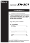
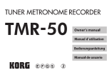
Panel descriptions
Top Panel
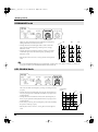
EXT IN (p. 49)
OSC 1/OSC 2 (p. 28)
Here you can play sound from a
device connected to the INPUT jacks.
You can also cancel a vocal or other
sound that is localized at the center of
audio you input.
This is the creative core, where the process of
sound production on the synthesizer begins.
It generates the waveform that determines the
character of the sound, and determines the pitch.
D BEAM (p. 20)
PITCH ENV (p. 31)
This creates time-varying changes in pitch, such as
the subtle pitch deviation that occurs when you
begin blowing a note on a brass instrument, or the
dramatic pitch swoop of an electronic drum.
You can move your hand
above this sensor to control
the pitch or volume.
MASTER VOL Knob
(p. 16)
This sets the volume of the
entire SH-201.
ARPEGGIO (p. 22)
This section lets you
produce an arpeggio
simply by holding down a
chord on the keyboard.
RECORDER (p. 24)
This section lets you
record your performance
on the SH-201.
TEMPO Button/TAP
Button
Here you can specify the
tempo of the arpeggio and
the recorder.
OCT UP/DOWN Buttons (p. 18)
These buttons shift the keyboard’s pitch range up or down.
PORTAMENTO Button (p. 19)
Portamento creates a smooth transition in pitch between two notes.
SOLO/LEGATO Button (p. 19)
Use this button to simulate the performance techniques of
monophonic instruments.
AUDIO FILTER
(p. 50)
This lets you vary the brightness
of the sound from an audio source
connected to the INPUT jacks, or
add a distinctive tonal character.
DUAL/SPLIT Button (p. 46)
Pitch Bend/Modulation Lever (p. 18)
While you play, move this lever to the left or right to
vary the pitch.
Move the lever away from yourself to apply vibrato.
Rear Panel
2
This button lets you layer two different sounds that have been created
by the OSC 1/2, MIX/MOD, FILTER, and AMP sections, or play two
sounds independently in the left and right areas of the keyboard.
UPPER Button/LOWER Button (p. 46)
Use these buttons to select the tone you want to edit using the panel
controls.
SH-201_r_e.book 3 ページ 2006年4月27日 木曜日 午前11時28分
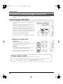
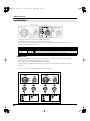
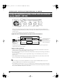
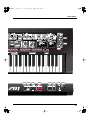
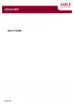
Panel descriptions
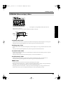
MIX/MOD
(p. 32)
This mixes the
waveforms
generated by OSC 1
and OSC 2 to create
a richer sound.
Here you can also
boost or cut the lowfrequency range.
FILTER (p. 34)
AMP (p. 38)
This adjusts the brightness or thickness of the sound
produced in the MIX/MOD section. Here you can
also add a distinctive tonal character that is typical of
synthesizer sounds.
This determines the loudness of the sound that has
passed through the FILTER section. Here you can
also distort the sound to make it more powerful.
AMP ENV (p. 38)
FILTER ENV (p. 37)
Here you can create time-varying changes in tone,
such as the way in which a note played on a piano
begins with a bright tone and gradually becomes
more mellow.
Here you can create time-varying changes in volume,
such as the way in which a note played on a piano
gradually diminishes, or the way in which notes on a
bowed-string instrument begin gradually.
EFFECTS
(p. 44)
Here you can add
depth and
spaciousness to the
sound by applying
effects such as echo
or reverberation to
simulate the
acoustic character
of a room or hall.
GROUP/BANK/NUMBER Buttons (p. 16)
LFO 1/LFO 2 (p. 40)
Here you can apply cyclic change to the sound,
such as modulating the pitch to create vibrato,
or modulating the volume to create tremolo.
Use these buttons to select the patch you want to play.
If the ARPEGGIO SELECT button’s indicator is lit, these
buttons will select an arpeggio template (p. 23).
WRITE Button/CANCEL Button (p. 48)
Use these buttons to save a sound you’ve created.
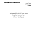
PEDAL Jack (p. 21)
INPUT Jacks (p. 49)
OUTPUT Jacks (p. 13)
Connect a pedal switch (DP series;
sold separately) or expression pedal
(EV-5; sold separately) to this jack.
Connect your digital audio
player, CD player, or sampler
to these jacks.
Connect your monitor
speakers or stereo set to these
jacks.
POWER Switch
(p. 14)
This switch turns the
power on/off.
USB Connector (p. 54)
Connect this to your computer.
MIDI Connectors (p. 58)
PHONES Jack (p. 13)
DC IN Jack (p. 12)
Connect other MIDI devices to
these connectors.
Connect headphones (sold
separately) to this jack.
Connect the included
AC adaptor to this jack.
3
SH-201_r_e.book 4 ページ 2006年4月27日 木曜日 午前11時28分
Contents
Panel descriptions ..................................................................................2
Main features...........................................................................................7
USING THE UNIT SAFELY......................................................................8
IMPORTANT NOTES .............................................................................10
Before you begin...................................................................................12
Making the connections........................................................................................................................... 12
Connecting the power adaptor ................................................................................................... 12
Connecting headphones or speakers.......................................................................................... 13
Turning the power on/off....................................................................................................................... 14
Turning the power off .................................................................................................................. 14
Basic structure of the SH-201..............................................................15
How sound is produced .......................................................................................................................... 15
Playing sounds .....................................................................................16
Adjusting the volume (MASTER VOL)................................................................................................. 16
Selecting a sound to play (GROUP/BANK/NUMBER) .................................................................... 16
About Patches ................................................................................................................................ 17
Restoring the original settings (Factory Reset) ......................................................................... 17
Adding expression to your playing (Velocity)..................................................................................... 18
Varying the pitch of the notes you play/Adding vibrato (Pitch Bend/Modulation lever) .......... 18
Shifting the pitch range of the keyboard (OCT UP/DOWN) ............................................................ 18
Smoothly connecting the pitch of two notes (PORTAMENTO)........................................................ 19
Playing monophonically (SOLO/LEGATO) ........................................................................................ 19
Moving your hand to vary the pitch or volume (D BEAM)............................................................... 20
Changing the pitch (PITCH)........................................................................................................ 20
Changing the volume to add expression to your performance (EXPRESS) ......................... 20
Changing the brightness or other aspects of the sound (FILTER/ASSIGN)........................ 21
Sustaining the notes (Hold pedal).......................................................................................................... 21
Adding dynamics to your performance (Expression pedal).............................................................. 21
Automatically playing arpeggios (ARPEGGIO).................................................................................. 22
Playing arpeggios (ON/HOLD) ................................................................................................. 22
Selecting how the arpeggio is to sound (SELECT)................................................................... 23
Recording your performance (RECORDER) ........................................................................................ 24
Recording ....................................................................................................................................... 24
Saving a recorded phrase............................................................................................................. 25
Playback.......................................................................................................................................... 26
Creating sounds....................................................................................27
How sounds are created .......................................................................................................................... 27
Specifying the waveform and pitch (OSC) ........................................................................................... 28
OSC 1 (oscillator 1) button/OSC 2 (oscillator 2) button.......................................................... 28
WAVE buttons............................................................................................................................... 28
PITCH knob ................................................................................................................................... 29
DETUNE knob............................................................................................................................... 29
PW/FEEDBACK (Pulse Width/Feedback) knob..................................................................... 30
INTERVAL buttons ...................................................................................................................... 30
PITCH ENV (pitch envelope) sliders ......................................................................................... 31
Combining waveforms to create rich or metallic sounds (MIX/MOD)........................................... 32
TYPE button................................................................................................................................... 32
BALANCE knob ............................................................................................................................ 33
LOW FREQ (low frequency) button........................................................................................... 33
4
SH-201_r_e.book 5 ページ 2006年4月27日 木曜日 午前11時28分
Contents
Specifying the brightness and thickness of the sound (FILTER)....................................................... 34
TYPE button................................................................................................................................... 34
SLOPE button ................................................................................................................................ 35
CUTOFF knob................................................................................................................................ 35
RESONANCE knob ...................................................................................................................... 36
KEY FOLLOW knob ..................................................................................................................... 36
FILTER ENV (filter envelope) sliders......................................................................................... 37
Specifying how the sound begins and ends (AMP) ............................................................................ 38
LEVEL knob ................................................................................................................................... 38
AMP ENV (amp envelope) sliders ............................................................................................. 38
Creating a powerful, distorted sound (OVERDRIVE) ........................................................................ 39
OVERDRIVE button ..................................................................................................................... 39
Modulating the sound (LFO).................................................................................................................. 40
LFO 1 button/LFO 2 button ........................................................................................................ 40
SHAPE buttons.............................................................................................................................. 40
RATE knob ..................................................................................................................................... 41
DESTINATION 1 .......................................................................................................................... 42
DESTINATION 2 .......................................................................................................................... 43
Adding depth and spaciousness to the sound (EFFECTS)................................................................. 44
EDIT button.................................................................................................................................... 44
FX ON (effect on) button.............................................................................................................. 44
TIME knob...................................................................................................................................... 45
DEPTH knob .................................................................................................................................. 45
Combining two sounds (DUAL/SPLIT)............................................................................................... 46
Layering two sounds to play them simultaneously (DUAL) ................................................. 46
Playing different sounds in the right and left hands (SPLIT)................................................. 47
Saving a sound you create (WRITE) ...................................................................................................... 48
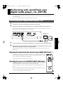
Performing with sound from your digital audio player, etc.
(EXT IN) ..................................................................................................49
Connecting your digital audio player, etc. ........................................................................................... 49
Adjusting the volume from the external source (INPUT VOL knob) ................................... 49
Canceling the center sound (CENTER CANCEL ON button) ............................................... 49
Modifying the sound from the external source (AUDIO FILTER) ................................................... 50
FILTER ON button........................................................................................................................ 50
TYPE button................................................................................................................................... 50
SLOPE button ................................................................................................................................ 51
CUTOFF knob................................................................................................................................ 51
RESONANCE knob ...................................................................................................................... 51
Using the keyboard to play sound from an external source (WAVE - EXT IN) ............................. 52
Producing sound from the external device only when you play the keyboard .................. 53
Using the SH-201 together with your computer or another sound
module ...................................................................................................54
Using your computer to record sound or performance data from the SH-201 (USB).................... 54
USB audio signal flow .................................................................................................................. 55
Creating sounds in greater detail (Editor)/
Using your computer to manage patches (Librarian)......................................................................... 56
Using SH-201 Editor to create sounds and arpeggios ............................................................. 56
Using SH-201 Librarian to manage patches .............................................................................. 56
SH-201 Editor System requirements .......................................................................................... 57
Using the SH-201 as a controller or a sound module (MIDI)............................................................. 58
About MIDI connectors................................................................................................................ 58
MIDI channels................................................................................................................................ 58
Using an external sequencer to play the SH-201’s internal sound generator (MIDI IN).... 59
Using the SH-201’s keyboard and knobs to play an external sound module
(MIDI OUT).................................................................................................................................... 59
5
SH-201_r_e.book 6 ページ 2006年4月27日 木曜日 午前11時28分
Contents
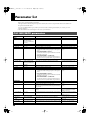
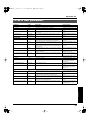
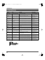
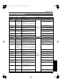
Parameter list ........................................................................................60
OSC MIX/MOD parameters................................................................................................................... 60
FILTER & AMP parameters .................................................................................................................... 61
LFO parameters ........................................................................................................................................ 62
EFFECTS parameters ............................................................................................................................... 63
PATCH COMMON parameters............................................................................................................. 64
ARPEGGIO parameters........................................................................................................................... 66
About arpeggio styles................................................................................................................... 67
SYSTEM COMMON parameters ........................................................................................................... 68
Other parameters...................................................................................................................................... 70
Setting the SPLIT POINT......................................................................................................................... 71
Setting the PITCH BEND RANGE......................................................................................................... 71
Control change message list ...............................................................72
MIDI implementation chart ...................................................................73
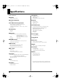
Specifications........................................................................................74
Block diagram .......................................................................................75
Panel index ............................................................................................76
Index.......................................................................................................78
Patch list ................................................................................................84
6
SH-201_r_e.book 7 ページ 2006年4月27日 木曜日 午前11時28分
Main features
Operating layout that’s faithful to synthesizer basics
The operating panel is laid out in a way that helps you intuitively understand how a synthesizer produces sound.
If you’re using a synthesizer for the first time to create sound you’ll find the SH-201 easy to learn, and if you’re
familiar with the basics of analog synthesizers you’ll be able to start using it immediately even without the
owner’s manual.
High-quality and practical analog modeling sounds
The SH-201 contains an analog modeling sound generator that distills the essence of Roland’s sound-generating
technology. From familiar synth leads and basses to motion pads and synth sounds for contemporary dance
music, the SH-201 gives you a broad variety of top-notch sounds.
Audio input jack that’s great for DJ performance
The SH-201 is equipped with audio input jacks for connecting your digital audio player or an external sampler.
You can modify these sounds in real time by turning the knobs to control the dedicated filter that’s built-in. You
can also use an external audio source as the oscillator for the sound generation section, and use the keyboard or
the arpeggiator to apply rhythm variation to the sound (p. 49).
Enhanced linkage with your computer
The USB connector supports both USB-MIDI connection and USB audio input/output. The SH-201 comes with
dedicated editor software that provides full editing capability for creating more complex sounds or for
programming the internal arpeggiator, as well as librarian software for saving and managing your own sounds
(p. 56). The dedicated editor is also provided as a plug-in version that you can run from within your VSTicompatible DAW.
Use the D Beam controller for more visual performances
The SH-201’s D Beam controller lets you produce dramatic changes in the sound simply by moving your hand
above the sensor. You can use this to control a wide range of the settings that are assigned to the panel knobs. The
D Beam can add a more intensely visual element to your stage performance (p. 20).
Two-tone structure for creating diverse and expressive sounds
While the SH-201 is a mere 5.2 kg in weight, it packs the sound-generating power of two analog synthesizers,
letting you play upper and lower tones simultaneously. You can split the two tones to different areas of the
keyboard, or layer them to create rich and complex sounds (p. 46).
7
SH-201_r_e.book 8 ページ 2006年4月27日 木曜日 午前11時28分
For the U.K.
IMPORTANT: THE WIRES IN THIS MAINS LEAD ARE COLOURED IN ACCORDANCE WITH THE FOLLOWING CODE.
BLUE:
NEUTRAL
BROWN: LIVE
As the colours of the wires in the mains lead of this apparatus may not correspond with the coloured markings identifying
the terminals in your plug, proceed as follows:
The wire which is coloured BLUE must be connected to the terminal which is marked with the letter N or coloured BLACK.
The wire which is coloured BROWN must be connected to the terminal which is marked with the letter L or coloured RED.
Under no circumstances must either of the above wires be connected to the earth terminal of a three pin plug.
USING THE UNIT SAFELY
The
symbol alerts the user to important instructions
or warnings.The specific meaning of the symbol is
determined by the design contained within the
triangle. In the case of the symbol at left, it is used for
general cautions, warnings, or alerts to danger.
Used for instructions intended to alert
the user to the risk of death or severe
injury should the unit be used
improperly.
Used for instructions intended to alert
the user to the risk of injury or material
damage should the unit be used
improperly.
* Material damage refers
other adverse effects
respect to the home
furnishings, as well
animals or pets.
The
symbol alerts the user to items that must never
be carried out (are forbidden). The specific thing that
must not be done is indicated by the design contained
within the circle. In the case of the symbol at left, it
means that the unit must never be disassembled.
to damage or
caused with
and all its
to domestic
The ● symbol alerts the user to things that must be
carried out. The specific thing that must be done is
indicated by the design contained within the circle. In
the case of the symbol at left, it means that the powercord plug must be unplugged from the outlet.
001
005
• Before using this unit, make sure to read the
instructions below, and the Owner’s Manual.
• This unit should be used only with a stand that is
recommended by Roland.
..........................................................................................................
..........................................................................................................
002c
006
• Do not open (or modify in any way) the unit or its
AC adaptor.
• When using the unit with a stand recommended
by Roland, the rack or stand must be carefully
placed so it is level and sure to remain stable. If
not using a stand, you still need to make sure that
any location you choose for placing the unit
provides a level surface that will properly support
the unit, and keep it from wobbling.
..........................................................................................................
..........................................................................................................
003
• Do not attempt to repair the unit, or replace parts
within it (except when this manual provides
specific instructions directing you to do so). Refer
all servicing to your retailer, the nearest Roland
Service Center, or an authorized Roland
distributor, as listed on the “Information” page.
..........................................................................................................
004
• Never use or store the unit in places that are:
• Subject to temperature extremes (e.g., direct
sunlight in an enclosed vehicle, near a heating
duct, on top of heat-generating equipment); or
are
• Damp (e.g., baths, washrooms, on wet floors);
or are
• Humid; or are
• Exposed to rain; or are
• Dusty; or are
• Subject to high levels of vibration.
..........................................................................................................
8
008c
• Be sure to use only the AC adaptor supplied with
the unit. Also, make sure the line voltage at the
installation matches the input voltage specified on
the AC adaptor’s body. Other AC adaptors may
use a different polarity, or be designed for a
different voltage, so their use could result in
damage, malfunction, or electric shock.
..........................................................................................................
008e
• Use only the attached power-supply cord. Also,
the supplied power cord must not be used with
any other device.
..........................................................................................................
009
• Do not excessively twist or bend the power cord,
nor place heavy objects on it. Doing so can
damage the cord, producing severed elements
and short circuits. Damaged cords are fire and
shock hazards!
..........................................................................................................
SH-201_r_e.book 9 ページ 2006年4月27日 木曜日 午前11時28分
010
101b
• This unit, either alone or in combination with an
amplifier and headphones or speakers, may be
capable of producing sound levels that could
cause permanent hearing loss. Do not operate for
a long period of time at a high volume level, or at
a level that is uncomfortable. If you experience
any hearing loss or ringing in the ears, you should
immediately stop using the unit, and consult an
audiologist.
..........................................................................................................
• The unit and the AC adaptor should be located so
their location or position does not interfere with
their proper ventilation.
..........................................................................................................
011
• Do not allow any objects (e.g., flammable
material, coins, pins); or liquids of any kind
(water, soft drinks, etc.) to penetrate the unit.
..........................................................................................................
012b
• Immediately turn the power off, remove the AC
adaptor from the outlet, and request servicing by
your retailer, the nearest Roland Service Center,
or an authorized Roland distributor, as listed on
the “Information” page when:
• The AC adaptor, the power-supply cord, or the
plug has been damaged; or
101c
• This SH-201 for use only with Roland stand KS12. Use with other stands is capable of resulting in
instability causing possible injury.
..........................................................................................................
102c
• Always grasp only the plug on the AC adaptor
cord when plugging into, or unplugging from, an
outlet or this unit.
..........................................................................................................
103b
• At regular intervals, you should unplug the AC
adaptor and clean it by using a dry cloth to wipe
all dust and other accumulations away from its
prongs. Also, disconnect the power plug from the
power outlet whenever the unit is to remain
unused for an extended period of time. Any
accumulation of dust between the power plug
and the power outlet can result in poor insulation
and lead to fire.
..........................................................................................................
104
• Objects have fallen into, or liquid has been
spilled onto the unit; or
• Try to prevent cords and cables from becoming
entangled. Also, all cords and cables should be
placed so they are out of the reach of children.
..........................................................................................................
• The unit has been exposed to rain (or otherwise
has become wet); or
• Never climb on top of, nor place heavy objects on
the unit.
• If smoke or unusual odor occurs
• The unit does not appear to operate normally
or exhibits a marked change in performance.
..........................................................................................................
013
• In households with small children, an adult
should provide supervision until the child is
capable of following all the rules essential for the
safe operation of the unit.
..........................................................................................................
014
• Protect the unit from strong impact.
(Do not drop it!)
..........................................................................................................
015
• Do not force the unit’s power-supply cord to
share an outlet with an unreasonable number of
other devices. Be especially careful when using
extension cords—the total power used by all
devices you have connected to the extension
cord’s outlet must never exceed the power rating
(watts/amperes) for the extension cord. Excessive
loads can cause the insulation on the cord to heat
up and eventually melt through.
..........................................................................................................
106
..........................................................................................................
107c
• Never handle the AC adaptor or its plugs with
wet hands when plugging into, or unplugging
from, an outlet or this unit.
..........................................................................................................
108b
• Before moving the unit, disconnect the AC
adaptor and all cords coming from external
devices.
..........................................................................................................
109b
• Before cleaning the unit, turn off the power and
unplug the AC adaptor from the outlet.
..........................................................................................................
110b
• Whenever you suspect the possibility of lightning
in your area, disconnect the AC adaptor from the
outlet.
..........................................................................................................
016
• Before using the unit in a foreign country, consult
with your retailer, the nearest Roland Service
Center, or an authorized Roland distributor, as
listed on the “Information” page.
..........................................................................................................
023
• DO NOT play a CD-ROM disc on a conventional
audio CD player. The resulting sound may be of a
level that could cause permanent hearing loss.
Damage to speakers or other system components
may result.
..........................................................................................................
9
SH-201_r_e.book 10 ページ 2006年4月27日 木曜日 午前11時28分
IMPORTANT NOTES
291a
In addition to the items listed under “USING THE UNIT SAFELY” on pages 8–9, please read and observe the following:
Power Supply
301
• Do not connect this unit to same electrical outlet that is
being used by an electrical appliance that is controlled by
an inverter (such as a refrigerator, washing machine,
microwave oven, or air conditioner), or that contains a
motor. Depending on the way in which the electrical
appliance is used, power supply noise may cause this unit
to malfunction or may produce audible noise. If it is not
practical to use a separate electrical outlet, connect a
power supply noise filter between this unit and the
electrical outlet.
302
• The AC adaptor will begin to generate heat after long
hours of consecutive use. This is normal, and is not a
cause for concern.
307
• Before connecting this unit to other devices, turn off the
power to all units. This will help prevent malfunctions
and/or damage to speakers or other devices.
Placement
351
• Using the unit near power amplifiers (or other equipment
containing large power transformers) may induce hum.
To alleviate the problem, change the orientation of this
unit; or move it farther away from the source of interference.
352a
• This device may interfere with radio and television
reception. Do not use this device in the vicinity of such
receivers.
352b
• Noise may be produced if wireless communications
devices, such as cell phones, are operated in the vicinity of
this unit. Such noise could occur when receiving or initiating a call, or while conversing. Should you experience
such problems, you should relocate such wireless devices
so they are at a greater distance from this unit, or switch
them off.
354a
• Do not expose the unit to direct sunlight, place it near
devices that radiate heat, leave it inside an enclosed
vehicle, or otherwise subject it to temperature extremes.
Excessive heat can deform or discolor the unit.
355b
• When moved from one location to another where the
temperature and/or humidity is very different, water
droplets (condensation) may form inside the unit. Damage
or malfunction may result if you attempt to use the unit in
this condition. Therefore, before using the unit, you must
allow it to stand for several hours, until the condensation
has completely evaporated.
358
• Do not allow objects to remain on top of the keyboard.
This can be the cause of malfunction, such as keys ceasing
to produce sound.
10
360
• Depending on the material and temperature of the surface
on which you place the unit, its rubber feet may discolor
or mar the surface.
You can place a piece of felt or cloth under the rubber feet
to prevent this from happening. If you do so, please make
sure that the unit will not slip or move accidentally.
Maintenance
401a
• For everyday cleaning wipe the unit with a soft, dry cloth
or one that has been slightly dampened with water. To
remove stubborn dirt, use a cloth impregnated with a
mild, non-abrasive detergent. Afterwards, be sure to wipe
the unit thoroughly with a soft, dry cloth.
402
• Never use benzine, thinners, alcohol or solvents of any
kind, to avoid the possibility of discoloration and/or
deformation.
Repairs and Data
452
• Please be aware that all data contained in the unit’s
memory may be lost when the unit is sent for repairs.
Important data should always be backed up in a
computer, or written down on paper (when possible).
During repairs, due care is taken to avoid the loss of data.
However, in certain cases (such as when circuitry related
to memory itself is out of order), we regret that it may not
be possible to restore the data, and Roland assumes no
liability concerning such loss of data.
SH-201_r_e.book 11 ページ 2006年4月27日 木曜日 午前11時28分
IMPORTANT NOTES
Additional Precautions
551
• Please be aware that the contents of memory can be
irretrievably lost as a result of a malfunction, or the
improper operation of the unit. To protect yourself against
the risk of loosing important data, we recommend that
you periodically save a backup copy of important data
you have stored in the unit’s memory in a computer.
552
• Unfortunately, it may be impossible to restore the contents
of data that was stored in the unit’s memory or a
computer once it has been lost. Roland Corporation
assumes no liability concerning such loss of data.
553
• Use a reasonable amount of care when using the unit’s
buttons, sliders, or other controls; and when using its jacks
and connectors. Rough handling can lead to malfunctions.
556
• When connecting / disconnecting all cables, grasp the
connector itself—never pull on the cable. This way you
will avoid causing shorts, or damage to the cable’s
internal elements.
558a
• To avoid disturbing your neighbors, try to keep the unit’s
volume at reasonable levels. You may prefer to use
headphones, so you do not need to be concerned about
those around you (especially when it is late at night).
559a
• When you need to transport the unit, package it in the box
(including padding) that it came in, if possible. Otherwise,
you will need to use equivalent packaging materials.
561
• Use only the specified expression pedal (EV-5; sold
separately). By connecting any other expression pedals,
you risk causing malfunction and/or damage to the unit.
562 (New)
• Some connection cables contain resistors. Do not use
cables that incorporate resistors for connecting to this unit.
The use of such cables can cause the sound level to be
extremely low, or impossible to hear. For information on
cable specifications, contact the manufacturer of the cable.
566b
• The sensitivity of the D Beam controller will change
depending on the amount of light in the vicinity of the
unit. If it does not function as you expect, adjust the sensitivity as appropriate for the brightness of your location.
Handling CD-ROMs
801
• Avoid touching or scratching the shiny underside
(encoded surface) of the disc. Damaged or dirty CD-ROM
discs may not be read properly. Keep your discs clean
using a commercially available CD cleaner.
11
SH-201_r_e.book 12 ページ 2006年4月27日 木曜日 午前11時28分
Before you begin
Making the connections
921
* To prevent malfunction and/or damage to speakers or other devices, always turn down the volume, and turn off the power
on all devices before making any connections.
Connecting the power adaptor
Connect the included AC adaptor (PSB-1U) to the DC IN jack located on the SH-201’s rear panel.
To the Power Outlet
Cord Hook
The cord of
the supplied
AC Adaptor
AC Adaptor
924
* To prevent the inadvertent disruption of power to your unit (should the plug be pulled out accidentally), and to avoid
applying undue stress to the AC adaptor jack, anchor the power cord using the cord hook, as shown in the illustration.
12
SH-201_r_e.book 13 ページ 2006年4月27日 木曜日 午前11時28分
Before you begin
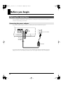
Connecting headphones or speakers
Since the SH-201 does not contain speakers, it cannot produce sound by itself. In order to produce sound, you
must connect monitor speakers, a stereo set or other audio system, or headphones.
Connecting monitor speakers or a stereo set
Use the appropriate cables to connect the OUTPUT jacks on the SH-201’s rear panel to your monitor speakers
or stereo set.
* In order to take full advantage of the SH-201’s capabilities, we recommend that you make connections in stereo.
If you’re making connections in monaural, connect to the OUTPUT L (MONO) jack.
Mixer etc.
Monitor Speakers
(powered)
Power Amplifier
Connecting headphones
Connect your stereo headphones to the PHONES jack on the rear panel of the SH-201.
Stereo Headphones
* Sound will be sent out from the OUTPUT jacks even if headphones are connected.
13
SH-201_r_e.book 14 ページ 2006年4月27日 木曜日 午前11時28分
Before you begin
Turning the power on/off
941
* Once the connections have been completed (p. 12, p. 13), turn on power to your various devices in the order specified. By
turning on devices in the wrong order, you risk causing malfunction and/or damage to speakers and other devices.
1
Check the following points before you turn on the power.
• Are the connections made correctly?
• Is the power on all connected equipment turned off?
2
3
On the SH-201’s top panel, turn the MASTER VOL knob all the way to the left.
On the SH-201’s rear panel, press the POWER switch to select the “ON” position.
Lower Position
ON
942
* This unit is equipped with a protection circuit. A brief interval (a few seconds) after power up is required
before the unit will operate normally.
* Don’t touch the pitch bend lever located at the left of the keyboard while you’re turning on the power.
If you turn on the power while touching the pitch bend lever, the lever may fail to operate correctly.
4
5
Do not touch!
Switch on the power to the connected equipment and raise the volume to an appropriate level.
While playing the SH-201’s keyboard, slowly turn the MASTER VOL knob toward the right to an
appropriate volume.
Turning the power off
1
Check the following points before you turn off the power.
• Is the volume of the connected equipment turned to the minimum setting?
• Have you saved the sounds you created? (p. 48)
2
3
14
Switch off the power on the connected equipment.
Press the SH-201’s POWER switch to select the “OFF” position.
OFF
SH-201_r_e.book 15 ページ 2006年4月27日 木曜日 午前11時28分
Basic structure of the SH-201
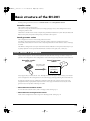
Broadly speaking, the SH-201 consists of a controller section and a sound generator section.
Controller section
The controller section is what you play.
This section conveys the performer’s actions (for example, “playing a note”) to the sound generator section,
causing it to produce sound.
The SH-201’s controller section consists of a keyboard, a pitch bend/modulation lever, the D Beam, the knobs and
buttons of the panel, and a pedal (sold separately) connected to the rear panel.
Sound generator section
The sound generator section is what actually produces the sound.
According to the performance data it receives from the controller section, the sound generator section
electronically creates the basic waveform of the sound, and specifies the tone and volume to create a wide range
of sounds.
The SH-201’s sound generator section provides numerous knobs and buttons on the panel to make it easy for you
to quickly adjust the various aspects that determine the sound (waveform, pitch, tone, volume, etc.).
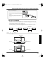
How sound is produced
Suppose that you play the “C” note on the keyboard. The keyboard sends a message of “the C note (key) was
played” to the sound generator. The sound generator receives this message and produces the sound of that note.
Controller section
(keyboard)
Sound generator
section
Performance data
(key pressed: C)
C
The “C” note has
a frequency of
261.6256 Hz
Next, suppose that you release that “C” note. The keyboard sends a message of “the C note (key) was released”
to the sound generator. The sound generator receives this message, and stops producing the sound of that note.
In reality, the controller section is sending more information than this to the controller section (such as the
strength with which you played that note). Based on the various types of information it receives, the sound
generator section can produce a wide range of sounds.
• More about the controller section
For more about the controller section, refer to “Playing sounds” starting on p. 16.
• More about the sound generator section
Details on the sound generator section are given in “Creating sounds” starting on p. 27.
15
SH-201_r_e.book 16 ページ 2006年4月27日 木曜日 午前11時28分
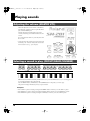
Playing sounds
Adjusting the volume (MASTER VOL)
This knob adjusts the overall volume of the SH-201,
and affects the output from the rear panel OUTPUT
jacks and the PHONES jack.
Turning the knob toward the right increases the
volume, and turning it toward the left decreases the
volume.
If you turn the knob all the way to the left, there will
be no sound.
* Turning this knob will not change the output volume of the
USB audio (p. 55). You’ll have to adjust the volume on the
USB-connected device (e.g., your computer).
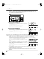
Selecting a sound to play (GROUP/BANK/NUMBER)
GROUP buttons (PRESET and USER), BANK buttons (A–D), and NUMBER buttons (1–8) for selecting patches
are located immediately above the keyboard.
Press the GROUP button, BANK button, and NUMBER button for the patch you want to play.
The patch will change immediately when you press a button.
Examples:
• If the USER A-1 patch is selected, pressing the NUMBER 6 button switches you to the USER A-6 patch.
• If the PRESET A-3 patch is selected, pressing the BANK C button switches you to the PRESET C-3 patch.
• If the PRESET B-5 patch is selected, pressing the USER button switches you to the USER B-5 patch.
16
SH-201_r_e.book 17 ページ 2006年4月27日 木曜日 午前11時28分
Playing sounds
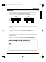
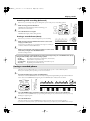
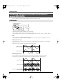
About Patches
The SH-201 lets you save the sounds you create.
Playing sounds
Sounds you create are called “patches.” You can use the panel buttons to select the patch you want to play.
Patches are organized into two groups; the preset group and the user group.
Each of these is further organized into four banks, each containing eight numbers, for a total of 32 patches.
2
User Group
Number
Number
3
4
5
6
7
8
1
2
3
4
5
6
7
8
A A-1 A-2 A-3 A-4 A-5 A-6 A-7 A-8
A A-1 A-2 A-3 A-4 A-5 A-6 A-7 A-8
B B-1 B-2 B-3 B-4 B-5 B-6 B-7 B-8
B B-1 B-2 B-3 B-4 B-5 B-6 B-7 B-8
C C-1 C-2 C-3 C-4 C-5 C-6 C-7 C-8
Bank
Bank
1
Preset Group
D D-1 D-2 D-3 D-4 D-5 D-6 D-7 D-8
C C-1 C-2 C-3 C-4 C-5 C-6 C-7 C-8
D D-1 D-2 D-3 D-4 D-5 D-6 D-7 D-8
32 read-only patches
32 rewritable patches
Preset group (PRESET)
These are 32 patches that are built into the SH-201.
You can’t rewrite the contents of these patches, but you can use them as a starting point when creating your own
new patches.
User group (USER)
These are 32 patches that you create and save.
For details on how to save your patches, refer to Saving a sound you create (WRITE) (p. 48).
Banks
The banks provide a convenient way to organize the 32 patches.
For example you might use bank A to hold the patches you use in the first song of your performance, and bank
B to hold the patches for the second song. Alternatively, you could put your synth bass patches in bank A and
your lead patches in bank B.
For details on how to select patches, refer to Selecting a sound to play (GROUP/BANK/NUMBER) (p. 16).
Restoring the original settings (Factory Reset)
You can restore the user patches and phrases (p. 24) and arpeggio settings (p. 66) to the factory-set condition.
When you carry out a Factory Reset, the user patches, phrases, and arpeggio settings you’ve created will
disappear.
1. While together holding down both the PRESET and USER buttons, switch on the SH-201.
The WRITE button and CANCEL button will blink.
2. Press the WRITE button.
If you decide to cancel, press the CANCEL button.
17
SH-201_r_e.book 18 ページ 2006年4月27日 木曜日 午前11時28分
Playing sounds
Adding expression to your playing (Velocity)
The SH-201’s keyboard produces volume (or brightness) changes in response to your playing dynamics.
The strength with which you play the keyboard is called the “key velocity.”
* If you want to change the way in which the sound responds to your keyboard playing velocity, adjust the FILTER & AMP
parameters (p. 61) LEVEL VELOCITY SENS (volume) and CUTOFF VELOCITY SENS (brightness).
Varying the pitch of the notes you play/
Adding vibrato (Pitch Bend/Modulation lever)
fig.Bender.e
• Moving the lever toward the left lowers the pitch of the notes
you’re playing (“Pitch Bend”); moving the lever toward the
right raises the pitch.
Lower
the pitch
Raise
the pitch
Apply
modulation
• Pushing the lever away from yourself adds vibrato
(“Modulation”) to the notes you’re playing.
• Moving the lever to left or right while pushing it away from
yourself applies pitch bend and modulation at the same time.
Pitch Bend effect
Modulation effect
Pitch bend range
Moving the lever all the way to the left (or right) lowers (or raises) the pitch by a whole step (two semitones).
* If you want to increase or decrease the range of change, refer to Setting the PITCH BEND RANGE (p. 71).
Modulation speed and shape
You can use the LFO 2 parameters SHAPE (p. 40) and RATE (p. 41) to vary the speed and shape of the vibrato
that is applied when you move the lever away from yourself.
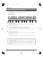
Shifting the pitch range of the keyboard (OCT UP/DOWN)
You can shift the range of the keyboard in one-octave steps, over a maximum of three octaves upward or
downward.
For example, if you’re using your right hand to play a synth bass sound, shifting the keyboard pitch down by one
octave will make it more convenient to play the keyboard.
fig.OCT-buttons
• Press the OCT UP button to shift the pitch upward. Each press shifts the keyboard one octave upward.
• Press the OCT DOWN button to shift the pitch downward. Each press shifts the keyboard one octave downward.
The OCT UP button’s indicator will light if the keyboard pitch range has been raised above the normal range.
The OCT DOWN button’s indicator will light if the range has been lowered.
You can return to the normal range by simultaneously pressing the OCT UP and OCT DOWN buttons. (The
indicators for both buttons go out.)
18
SH-201_r_e.book 19 ページ 2006年4月27日 木曜日 午前11時28分
Playing sounds
Playing sounds
Smoothly connecting the pitch of two notes
(PORTAMENTO)
You can make a smooth transition in pitch between one note and the next. This effect
is called “portamento.”
To apply portamento, press the PORTAMENTO button so its indicator is lit.
Changing the speed of the pitch change
To change the speed at which the pitch change occurs (i.e., the “portamento time”),
hold down the PORTAMENTO button and press one of the NUMBER buttons (1–8)
located immediately above the keyboard.
Pressing a higher-numbered NUMBER button selects a correspondingly longer
portamento time, producing a slower change in pitch.
You can also adjust the portamento time by holding down the PORTAMENTO button and turning the EFFECTS
TIME knob (p. 45).
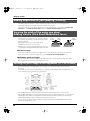
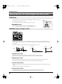
Playing monophonically (SOLO/LEGATO)
When playing sounds of instruments that are naturally monophonic, such as sax or
flute, this function will help your performance be more realistic.
• When you press the SOLO button so its indicator is lit, Solo and Legato are both
turned on.
• When you press the SOLO button once again so its indicator is blinking, only Solo
will be on.
Solo
Even if you play a chord on the keyboard, only a single note will sound. The key you
played last will sound.
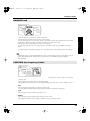
Legato
When you hold down one key and press another key, the sound will be maintained but the pitch will move to
that of the second key you pressed. You will not hear any attack for the second key you pressed.
This produces an effect similar to the hammering-on/off technique used by a guitarist.
This is also suitable for simulating the trill techniques used on wind instruments or string instruments.
Legato: OFF
Legato: ON
volume
volume
time
Key-on
Key-on
time
Key-on
Key-on
Using legato and portamento simultaneously
If you turn portamento on when legato is already on (i.e., when the SOLO button’s indicator is lit), you’ll be able
to control whether portamento is applied by the way you press the keys.
• Hold down a key while pressing the next key
Portamento will be applied.
The pitch of the currently sounding note will change smoothly to the pitch of the next key you pressed.
• Release a key before you press the next key
Portamento will not be applied.
When you press a key, the note will sound immediately at the corresponding pitch.
19
SH-201_r_e.book 20 ページ 2006年4月27日 木曜日 午前11時28分
Playing sounds
Moving your hand to vary the pitch or volume (D BEAM)
By moving your hand over the D Beam controller
located at the upper left of the keyboard, you can vary
the pitch or volume of the sound according to the height
of your hand.
The usable range of the D Beam controller
The diagram at left shows the
usable range of the D Beam
controller. Moving your hand
outside this range will produce no
effect.
Changing the pitch (PITCH)
Press the PITCH button located below the D Beam controller so it’s lit.
When you hold down a key and move your hand up or down above the D Beam controller, the pitch will change.
Press the PITCH button once again so its light goes off, and the pitch will no longer be affected when you move
your hand above the D Beam Controller.
Changing the volume to add expression to your performance (EXPRESS)
Press the EXPRESS button located below the D Beam controller so it’s lit.
When you hold down a key and move your hand up or down above the D Beam controller, the volume will
change, letting you add expression to your performance.
Press the EXPRESS button once again so its light goes off, and the volume will no longer be affected when you
move your hand above the D Beam controller.
Active Expression
By using EXPRESS with a patch that is set to DUAL (p. 46), you can obtain an Active Expression effect that
combines the two tones.
Only the UPPER tone will be heard when the volume is low, and the LOWER tone will be added as the volume
increases.
If you want to use Active Expression, hold down the CANCEL button and press the ACTIVE EXPRESSION
button, thus switching “ON” ACTIVE EXPRESSION, which is a PATCH COMMON parameter (p. 65).
20
SH-201_r_e.book 21 ページ 2006年4月27日 木曜日 午前11時28分
Playing sounds
Changing the brightness or other aspects of the sound (FILTER/ASSIGN)
Playing sounds
Press the FILTER/ASSIGN button located below the D Beam controller so it’s lit.
When you hold down a key and move your hand up or down above the D Beam controller, the brightness of the
sound (cutoff frequency of the filter; p. 35) will change.
Press the FILTER/ASSIGN button once again so its light goes off, and the brightness will no longer be affected
when you move your hand above the D Beam controller.
Selecting the parameter controlled by the D Beam
If you hold down the FILTER/ASSIGN button and move one of the top panel knobs, the D Beam controller will
have the same function as that knob. At this time you can also choose the direction in which the knob will be moved.
For example, suppose that you hold down the FILTER/ASSIGN button while you turn the LFO RATE knob (p. 41)
toward the right. Thereafter, when you move your hand closer to the D Beam controller while the FILTER/ASSIGN
button is lit, the LFO speeds up, just as if you had moved the LFO RATE knob toward the right.
For details on the parameters that you can control, refer to PATCH COMMON parameters (p. 64) CONTROLLER
ASSIGN - D BEAM (p. 65) and D BEAM - D BEAM POLARITY (p. 65).
* To set the D Beam Controller’s function to “FILTER” (changing the brightness of the sound), hold down the FILTER/
ASSIGN button and turn the FILTER CUTOFF knob.
Changing the sensitivity of the D Beam controller
If you’re performing under strong direct sunlight or strong artificial illumination, the D Beam controller will
be less sensitive.
In such cases, hold down the FILTER/ASSIGN button located below the D Beam controller and press one of
the NUMBER buttons (1–8) located immediately above the keyboard to change the sensitivity of the D Beam
controller.
The sensitivity setting is indicated by the number of NUMBER buttons that are lit red when you hold down
the FILTER/ASSIGN button. The more NUMBER buttons that are lit red, the higher the sensitivity setting.
Pressing a higher-numbered NUMBER button will increase the sensitivity.
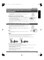
Sustaining the notes (Hold pedal)
fig.HoldPdl
If you connect a pedal switch (DP series; sold
separately) to the rear panel PEDAL jack, the
notes you play while holding down the pedal
will continue sounding even if you take your
hand off the keyboard. (This is called Hold.)
If you want to use a pedal switch as a hold
pedal, hold down the CANCEL button and
press the NUMBER 1 button before using it
(PEDAL ASSIGN (p. 69)).
Adding dynamics to your performance (Expression pedal)
fig.ExpPdl
If you connect an expression pedal (EV-5; sold
separately) to the rear panel PEDAL jack, you
can use the pedal to control the volume,
adding dynamic expression to your
performance.
If you want to use an expression pedal, hold
down the CANCEL button and press the
NUMBER 6 button before using it (PEDAL
ASSIGN (p. 69)).
d
Rolan
925
* Use only the specified expression pedal (EV-5; sold separately). By connecting any other expression pedals, you risk causing
malfunction and/or damage to the unit.
21
SH-201_r_e.book 22 ページ 2006年4月27日 木曜日 午前11時28分
Playing sounds
Automatically playing arpeggios (ARPEGGIO)
The SH-201’s arpeggiator lets you produce an arpeggio in the style you select simply by pressing a chord on the
keyboard.
Playing arpeggios (ON/HOLD)
• Press the ON button so its indicator is lit; the arpeggiator will be
turned on.
When you press a chord on the keyboard, an arpeggio will play
according to the settings stored in each patch.
• If you press the ON button once again so the button’s indicator
is blinking, the arpeggiator’s Hold function is turned on.
When you press a chord on the keyboard, an arpeggio will play
according to the settings stored in each patch, and will continue
playing even if you take your hand off the keyboard. When you
play a new chord, the arpeggio will also change.
To stop the arpeggio, turn off the arpeggiator.
To turn off the arpeggiator, press the ON button so its light goes
off.
Changing the arpeggio tempo
• TEMPO buttons
Use these to specify the tempo of the arpeggiator.
Press the upper (▲) button to make the tempo faster, or press the
lower (▼) button to make the tempo slower.
• TAP button
You can set the tempo by pressing this button three or more
times at quarter-note intervals of the desired tempo.
* The TAP button’s indicator will always be blinking at quarter-note
intervals of the arpeggio and recorder tempo (p. 24).
Playing arpeggios via MIDI
Normally, you can use the arpeggiator only from the SH-201’s own keyboard.
If you want to play the SH-201’s arpeggiator via note messages from your external sequencer or sequencer
software, set the KEYBOARD parameter (p. 69) REMOTE KEYBOARD to the “ON” setting.
22
SH-201_r_e.book 23 ページ 2006年4月27日 木曜日 午前11時28分
Playing sounds
Selecting how the arpeggio is to sound (SELECT)
1
Playing sounds
The SH-201 provides 32 ready-made variations of arpeggio, which are called “arpeggio templates.”
Press the SELECT button so its indicator is lit.
Now you can use the BANK buttons (A–D) and NUMBER
buttons (1–8) to select an arpeggio template.
The arpeggio templates are organized into four groups,
accessible using the BANK buttons, with eight templates at each.
2
Press the BANK button and NUMBER button of the arpeggio template you want to use.
The arpeggio template for the buttons you pressed is selected.
3
Press the SELECT button so its indicator is switched off.
The BANK buttons and NUMBER buttons return to their normal function—patch selection.
* You can also return to the normal state by pressing the blinking CANCEL button instead of pressing the SELECT button.
(The arpeggio template selection is valid in this case as well.)
* By using SH-201 Editor (p. 56) you can create your own original arpeggios that differ from these ready-made arpeggio
templates. For details, refer to the ARPEGGIO parameters (p. 66).
23
SH-201_r_e.book 24 ページ 2006年4月27日 木曜日 午前11時28分
Playing sounds
Recording your performance (RECORDER)
The Recorder function lets you record several measures of your keyboard performance or knob operations and
play back this recording repeatedly.
The recorded performance is called a “phrase.” You can record up to eight phrases, each up to eight measures long.
The SH-201’s recorder does not record the actual “sound” you’re hearing; rather, it records performance data (MIDI
messages) that provides an ongoing description of things, such as “which key was pressed, when, and how strongly.”
* The patch you’re using, patch selections during the phrase, and tempo changes are not recorded.
Recording
1
Press and release the REC button; the SH-201 enters REC
standby mode.
The REC button’s indicator starts blinking, and the metronome
begins sounding.
2
Specify the length of the phrase that you want to record.
In REC standby mode, the NUMBER buttons (1–8) are used to
specify the length (number of measures) for the phrase. The
number of lit buttons indicates the number of measures in the
phrase.
To specify the number of measures, press the NUMBER button for
the number of measures you want to record.
* If you specify the length of the phrase to be recorded, all performance data
previously recorded for that phrase will be erased.
3
Press the PLAY/STOP button.
A one-measure (four-beat) count is sounded, then recording
begins.
The blinking REC button’s indicator will change to steadily lit.
4
To stop recording, press the PLAY/STOP button once again.
Changing the tempo during recording
• TEMPO buttons
Use these to specify the tempo of the recorder/arpeggiator.
Press the upper (▲) button to make the tempo faster, or press the
lower (▼) button to make the tempo slower.
• TAP button
You can set the tempo by pressing this button three or more
times at quarter-note intervals of the desired tempo.
* The TAP button’s indicator will always be blinking at quarter-note
intervals of the recorder and arpeggio tempo (p. 22).
24
SH-201_r_e.book 25 ページ 2006年4月27日 木曜日 午前11時28分
Playing sounds
Practicing while recording (Rehearsal)
Here’s how you can temporarily stop recording while you’re in the process of recording a phrase.
2
While recording, press the REC button.
The REC button begins blinking. While it is blinking, your
performance is not recorded.
Playing sounds
1
Press the REC button once again.
The REC button lights, and recording resumes.
Erasing a recorded note (Erase)
Here’s how you can erase a note from the phrase you’re recording.
1
2
While recording, press the CANCEL button at the location of the
note(s) you want to erase.
All previously recorded notes are erased from the region for which you
continue to hold down the CANCEL button.
When you reach the end of the region from which you want to erase
notes, take your finger off of the CANCEL button.
Normal recording resumes.
You can choose the type of data that will be recorded or erased by pressing one of the BANK buttons (A–D)
during the REC standby state or while recording a phrase.
• A (All):
All of the following (B, C, D) listed below (Default state)
Pitch bender lever operations only
• B (Bender):
• C (Controller): Knob operations (only parameters in the table on p. 72)
• D (notes):
Keyboard’s performance data only
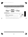
Saving a recorded phrase
The phrase you recorded will be lost if you switch off the SH-201’s power or select a different phrase.
Once you’ve created a phrase you like, you can save it as follows.
1
2
3
Hold down the REC button and press the WRITE button.
The indicator of the NUMBER button for the currently selected phrase begins blinking in red, while the indicators
of the other seven NUMBER buttons light in green. The WRITE button’s indicator will also blink.
Press the NUMBER button of the phrase number in which you want to save your recorded phrase.
The indicator of the NUMBER button you pressed begins blinking in red, and the indicator that was previously
blinking now lights in green.
Press the WRITE button.
The phrase will be saved. (The NUMBER buttons will revert to their usual role of selecting patches.)
* If you decide to cancel this operation, press the CANCEL button at any point before you press the WRITE button in step 3.
25
SH-201_r_e.book 26 ページ 2006年4月27日 木曜日 午前11時28分
Playing sounds
Playback
Selecting the phrase you want to play
1
Press and hold the REC button.
While you hold down the REC button, the NUMBER buttons (1–
8) function as phrase selection buttons.
The indicator of the NUMBER button for the currently selected
phrase number blinks in green, while the indicators of the other
seven NUMBER buttons light in green.
2
Continue holding down the REC button, and press the NUMBER button for the phrase that you want to play.
The indicator of the NUMBER button you pressed starts blinking in green, while the indicator that was previously
blinking changes to steadily lit green.
3
Release the REC button.
You have now selected a phrase.
The NUMBER buttons will return to their usual function of selecting patches.
Starting/stopping playback
4
Press the PLAY/STOP button.
Phrase playback begins.
The phrase will continue playing repeatedly until you press
PLAY/STOP once again.
5
Press the PLAY/STOP button once again to stop phrase
playback.
Changing the tempo of the phrase
• TEMPO buttons
Use these to specify the tempo of the recorder/arpeggiator.
Press the upper (▲) button to make the tempo faster, or press the
lower (▼) button to make the tempo slower.
• TAP button
You can set the tempo by pressing this button three or more
times at quarter-note intervals of the desired tempo.
* The TAP button’s indicator will always be blinking at quarter-note
intervals of the recorder and arpeggio tempo (p. 22).
26
SH-201_r_e.book 27 ページ 2006年4月27日 木曜日 午前11時28分
Creating sounds
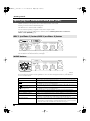
How sounds are created
The following diagram shows the basic process by which the SH-201 creates sounds.
fig.SH-Structure.e
OSC 1
Generates the
waveform and
specifies the pitch
MIX/MOD
FILTER
AMP
EFFECTS
Mixes
waveforms
Specifies the
brightness of
the sound
Specifies the
loudness of
the sound
Adds depth or
spaciousness
PITCH ENV
LFO 1
LFO 2
FILTER ENV
AMP ENV
Varies the pitch
at which the
sound begins
Modulates the pitch,
the brightness, or
the volume
Modulates the pitch,
the brightness, or
the volume
Varies the brightness
as the sound begins
or ends
Specifies how the
sound begins and
ends
Audio signals
Creating sounds
OSC 2
Generates the
waveform and
specifies the pitch
Control signals
The three elements of sound
There are three important elements that determine the character of a sound; the pitch, the brightness, and the volume.
On the SH-201, these three elements are specified by the following sections.
• Pitch:
OSC (oscillator; p. 28)
• Brightness: FILTER (filter; p. 34)
• Volume:
AMP (amplifier; p. 38)
First, use the OSC section to specify the pitch. Next, use the FILTER section to specify the brightness. Finally, use the
AMP section to specify the volume. This is the basic procedure for creating a sound.
In actuality, the brightness of the sound is dramatically affected by the waveform generated by the OSC section, but
the process is as described above.
Time-varying change in the sound (Envelope)
The OSC, FILTER, and AMP sections can vary the pitch, brightness, and volume of the sound over time.
For example, you can make the pitch fall momentarily at the beginning of each note, or make the volume of each note
gradually increase.
The way in which some aspect of a note changes over time is called the “envelope.” The envelope is specified by the
following sections.
• Pitch:
• Brightness:
• Volume:
PITCH ENV (pitch envelope; p. 31)
FILTER ENV (filter envelope; p. 37)
AMP ENV (amp envelope; p. 38)
Cyclic change in the sound (Modulation)
The OSC, FILTER, and AMP sections can also be controlled by an LFO (Low Frequency Oscillator; p. 40) to cyclically
vary aspects of the sound such as pitch (producing vibrato) or volume (producing tremolo).
Cyclic change applied to the pitch, tone, or volume in this way is called “modulation.”
The SH-201 has two LFO units, allowing you to simultaneously apply modulation of differing speeds and
waveforms.
A patch suitable as a starting point for creating sound “from scratch” is provided at the end of preset group
bank D. Use this patch as desired.
27
SH-201_r_e.book 28 ページ 2006年4月27日 木曜日 午前11時28分
Creating sounds
Specifying the waveform and pitch (OSC)
The OSC (oscillator) section produces the waveform that is the basis of the sound.
Selecting a waveform will also determine the pitch.
The SH-201 has two oscillators; OSC 1 and OSC 2.
You can use these separately, or together to create rich or complex sounds.
For details on how you can combine the two oscillators, refer to Combining waveforms to create rich or
metallic sounds (MIX/MOD) (p. 32).
OSC 1 (oscillator 1) button/OSC 2 (oscillator 2) button
fig.OSC-buttons
Use these buttons to specify whether you’re making settings for OSC 1 or OSC 2.
Press the button for the desired oscillator; it will light.
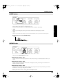
WAVE buttons
fig.WAVE-buttons
Use these buttons to select the waveform that is the basis of the sound. One of the indicators will light to indicate
the waveform that’s selected. Press the right button to move clockwise through the selections, or the left button
to move counterclockwise.
Lit indicator
(Sawtooth wave)
(Square wave)
(Asymmetrical square (pulse) wave)
(Triangle wave)
(Sine wave)
NOISE
FB OSC (Feedback oscillator)
SUPER SAW
EXT IN (External In)
28
Description
This waveform contains the fundamental frequency (sine wave) plus all of its integer multiples (overtones) at a fixed proportion.
This waveform contains the fundamental frequency (sine wave) plus its odd-numbered integer multiples (overtones) at a fixed proportion.
The overtone structure will change significantly depending on the width of the upper portion (pulse width, p. 30) of the waveform.
This waveform contains the fundamental frequency (sine wave) plus its even-numbered integer multiples (overtones) at a fixed proportion.
A waveform with no overtones (harmonics). It consists of only one single frequency.
A waveform containing all frequencies. Use this for percussion sounds or sound effects.
Produces a tone containing high overtones, similar to feedback on a guitar. Ideal for creating aggressive, cutting sounds.
A sound resembling seven sawtooth waves played simultaneously. Pitch-shifted sounds
are added to a core sound. Ideal for creating string sounds and other rich tones.
This plays the sound from the audio source connected to the rear panel INPUT jacks. Refer
to p. 52.
* There will be no sound if nothing is connected to the INPUT jacks or if you have turned
down the volume of the connected source or the INPUT VOL (p. 49).
SH-201_r_e.book 29 ページ 2006年4月27日 木曜日 午前11時28分
Creating sounds
PITCH knob
fig.PITCH-knob
This knob specifies the pitch.
Creating sounds
• Turning the knob toward the right raises the pitch in semitone steps.
Turning the knob all the way raises the pitch one octave above the center setting.
• Turning the knob toward the left lowers the pitch in semitone steps.
Turning the knob all the way lowers the pitch one octave below the center setting.
WIDE button
This button expands the range of the PITCH knob by a multiple of three.
If you press the WIDE button so it’s lit, the PITCH knob will have a range of +/-3 octaves.
If you press the WIDE button once again so the light is off, the PITCH knob will return to a range of +/-1 octave.
Using the PITCH knob
For example, by setting the OSC 2 pitch five semitones (a perfect fourth) below OSC 1, you can play a single key
to produce a heavy sound similar to when two adjacent strings are played at the same fret on strings 3–6 of a guitar.
You can also use the PITCH setting to shift the sound to the range in which you’ll usually be playing it. For
example, if you’re creating a sound that’s normally played in a low range, such as synth bass, you can set
PITCH one octave down.
DETUNE knob
fig.DETUNE-knob
This knob provides a finer pitch adjustment than the PITCH knob.
You can use it to create a slight difference in the pitches of OSC 1 and OSC 2 so that the sound is slightly
modulated, producing a richer tone (Detune effect).
• Turning the knob toward the right raises the pitch.
Turning the knob all the way raises the pitch 50 cents above the center setting.
• Turning the knob toward the left lowers the pitch.
Turning the knob all the way lowers the pitch 50 cents below the center setting.
What is a “cent”?
One cent is 1/100th of a semitone. Fifty cents is half a semitone.
29
SH-201_r_e.book 30 ページ 2006年4月27日 木曜日 午前11時28分
Creating sounds
PW/FEEDBACK (Pulse Width/Feedback) knob
fig.PWFB-knob
This knob is effective only if specific waveforms are selected by the WAVE buttons (p. 28).
When
(asymmetrical square (pulse) wave) is selected
The knob specifies the width of the high portion of the waveform (i.e., the pulse width) as a percentage of the
entire cycle.
• Turning the knob toward the left narrows the pulse width, approaching a square wave (
50%).
, pulse width =
• Turning the knob toward the right broadens the pulse width, producing a distinctive sound.
When FB OSC is selected
The knob specifies the amount of output sound that is to be returned (fed back) to the input.
Turning the knob toward the right increases the feedback, producing more overtones and making the sound more
aggressive.
When SUPER SAW is selected
The knob specifies the amount of pitch spread between the seven sawtooth waves layered within a single
oscillator. Turning the knob toward the right will increase the pitch spread.
(In this case, the DETUNE knob will adjust all seven sawtooth waves by the same pitch amount.)
INTERVAL buttons
fig.INTERVAL-buttons
-OCT (minus octave) button
This button lowers the OSC 2 pitch one octave below that of OSC 1.
Pressing a single key will produce a rich sound, as though you had also played another key one octave below.
5th button
If you press this button, the OSC 2 pitch will be seven semitones (a perfect fifth) higher than OSC 1.
Playing a single key will produce a fifth chord, creating a heavy sound.
* If you press the -OCT button and the 5th button simultaneously, the OSC 2 pitch will be the same as the OSC 1 pitch.
* Parameters other than pitch will not change.
30
SH-201_r_e.book 31 ページ 2006年4月27日 木曜日 午前11時28分
Creating sounds
PITCH ENV (pitch envelope) sliders
fig.P-ENV-sliders
Brass instruments such as trumpet sometimes produce a slight shift in pitch when you begin blowing a note. You
can use the pitch envelope to create this type of change in pitch over time.
Creating sounds
fig.PitchEnv.e
pitch
DEPTH
A
D
time
A (attack time) slider
Specifies the time from when you play a key until the pitch reaches the highest (or lowest) point.
Moving the slider upward lengthens the time, and moving it downward shortens the time.
D (decay time) slider
Specifies the time from when the pitch reaches its highest (or lowest) point until it returns to the pitch of the key
you pressed.
Moving the slider upward lengthens the time, and moving it downward shortens the time.
DEPTH slider
Specifies the direction and amount of the pitch change.
• Moving the slider upward (in the “+” direction) causes the pitch to initially rise, and then return to the pitch of
the key you pressed. Moving the slider farther will produce a greater rise in pitch.
• Moving the slider downward (in the “-” direction) causes the pitch to initially fall, and then return to the pitch
of the key you pressed. Moving the slider farther will produce a greater fall in pitch.
* DEPTH can be set independently for OSC 1 and OSC 2. For example, you could leave the OSC 1 pitch fixed, and change the
pitch only for OSC 2.
When the OSC 1 button is lit, moving the DEPTH knob will change the OSC 1 DEPTH. When the OSC 2 button is lit,
moving the DEPTH knob will change the OSC 2 depth.
Using PITCH ENV
If you want the sound to rise briefly, as at the beginning of a trumpet note, set A and D to very short times
and move the DEPTH slightly in the “+” direction.
By setting A to the shortest setting (with the slider all the way down), D to a somewhat longer setting, and
DEPTH all the way up, you can create a down-swooping pitch similar to the electronic drums that were
popular in the 1980’s.
31
SH-201_r_e.book 32 ページ 2006年4月27日 木曜日 午前11時28分
Creating sounds
Combining waveforms to create rich or metallic
sounds (MIX/MOD)
You can combine the sounds of OSC 1 and OSC 2 to create more complex sounds.
TYPE button
fig.MIX-TYPE-button
This button selects how OSC 1 and OSC 2 are to be combined.
Press the button to light the indicator for the desired combination.
Pressing the button successively cycles you through the settings in this order: MIX –> SYNC –> RING –> MIX –> ... .
• MIX
The sounds of OSC 1 and OSC 2 will be heard together.
You can create a rich sound by slightly shifting the pitch of the two oscillators or by layering different waveforms.
• SYNC (oscillator sync)
OSC 1 will be forced to restart its cycle in synchronization with the beginning of each OSC 2 cycle, generating a
complex waveform.
This is effective when the OSC 1 pitch is higher than the OSC 2 pitch.
fig.OscSync.e
OSC 1 waveform
(output waveform)
OSC 2 waveform
• RING (ring modulator)
OSC 1 and OSC 2 will be multiplied to create a complex, metallic-sounding tone reminiscent of a bell.
It will be easier to produce a ring modulator effect if you set OSC 1 and OSC 2 to different pitches.
fig.RingMod.e
OSC 1 waveform
OSC 2 waveform
The two waveforms multiplied
(output waveform)
32
SH-201_r_e.book 33 ページ 2006年4月27日 木曜日 午前11時28分
Creating sounds
BALANCE knob
fig.BALANCE-knob
This knob adjusts the volume balance of OSC 1 and OSC 2.
Creating sounds
• Turning the knob toward the left increases the volume of OSC 1.
If you turn the knob all the way to the left, only the sound of OSC 1 will be output, and OSC 2 will not be heard.
When TYPE is “RING,” the sound to which ring modulation is applied will be output.
• Turning the knob toward the right increases the volume of OSC 2.
If you turn the knob all the way to the right, only the sound of OSC 2 will be output, and OSC 1 will not be
heard.
* If you find it difficult to distinguish the oscillator sync or ring modulator effect, turn the BALANCE knob toward the left.
Immediately after you’ve selected the PRESET D-8 patch, you will be hearing only the sound of OSC 1 (a state in
which the BALANCE knob is turned all the way to the left). If you want OSC 2 to be heard, adjust the
BALANCE knob.
LOW FREQ (low frequency) button
fig.LOWFREQ-button
This button selects whether the low frequency range will be boosted to produce a heavy sound or cut to produce
a lighter sound.
Press the button to select the indicator for the desired setting.
Pressing the button successively cycles you through the settings in this order: CUT –> FLAT –> BOOST –> CUT –> ... .
• CUT
The low frequency range will be cut, producing a lighter sound.
Since this will make the high frequency range more prominent, it may make the sound crisper.
• FLAT
The low frequency range will neither be boosted nor cut.
• BOOST
The low frequency range will be boosted, producing a heavier sound.
This setting is useful when you’re creating a synth bass sound or a rich strings sound.
33
SH-201_r_e.book 34 ページ 2006年4月27日 木曜日 午前11時28分
Creating sounds
Specifying the brightness and thickness of the sound
(FILTER)
TYPE button
fig.FILTER-TYPE-button
This button selects the type of filter that is applied to the waveform.
Press the button so the indicator for the desired filter is lit.
Pressing the button successively cycles you through the settings in this order: LPF –> HPF –> BPF –> BYPASS
–> LPF –> ... .
Filter types
fig.FilterTypes.e
LPF
HPF
BPF
(Low Pass Filter)
(High Pass Filter)
(Band Pass Filter)
level
partials
which
are cut
level
level
partials
which
are cut
partials
which
are cut
frequency
frequency
partials
which
are cut
frequency
• LPF (Low Pass Filter)
This cuts the frequency region above the cutoff frequency, making the sound more mellow.
This is the most commonly used filter.
• HPF (High Pass Filter)
This cuts the frequency region below the cutoff frequency, emphasizing the high-frequency region.
You can use this when you want to create percussion instrument sounds with a distinctive high range.
• BPF (Band Pass Filter)
This passes only the frequencies in the region of the cutoff frequency, and cuts the remaining frequency regions.
You can use this to create distinctive sounds.
If you select this filter type when you’ve selected “NOISE” as the OSC waveform, you will hear only a limited
region of the frequency components of the noise waveform; this lets you play notes that have a sense of pitch.
• BYPASS
Bypasses the filter. The unfiltered waveform of the oscillator will be output.
34
SH-201_r_e.book 35 ページ 2006年4月27日 木曜日 午前11時28分
Creating sounds
SLOPE button
fig.FILTER-SLOPE-button
This button selects the slope (steepness) of the filter.
Press the button so the indicator for the desired slope is lit.
Each time you press the button you can alternate between the -12 dB and -24 dB setting.
Creating sounds
• -12 dB
The filter slope will be gentle, allowing some of the sound near the cutoff frequency to remain.
• -24 dB
The filter slope will be steep, cutting most of the sound immediately above (or below) the cutoff frequency.
Example: LPF (Low Pass Filter) SLOPE settings
level
-24 dB
-12 dB
cutoff frequency
frequency
CUTOFF knob
fig.FILTER-CUTOFF-knob
This specifies the cutoff frequency of the filter.
When the filter TYPE is “LPF”
Turning the knob toward the right brightens the sound, while turning it toward the left darkens (mellows) the
sound.
When the filter TYPE is “HPF”
Turning the knob toward the right will make the sound lighter (less thick), and turning it toward the left will
make the sound heavier (thicker).
When the filter TYPE is “BPF”
Turning the knob toward the right will allow a higher range of frequencies to be heard, and turning it toward the
left will allow a lower range of frequencies to be heard.
* When the filter TYPE is “BYPASS,” turning the knob will not affect the sound.
35
SH-201_r_e.book 36 ページ 2006年4月27日 木曜日 午前11時28分
Creating sounds
RESONANCE knob
fig.FILTER-RESONANCE-knob
• Turning the knob toward the right will boost the sound in the
region near the cutoff frequency, producing a more strongly
distinctive sound.
• Turning the knob toward the left will remove the boost from the
sound in the region near the cutoff frequency, producing a less
distinctive sound.
LPF
BPF
HPF
level
High
frequency
Cutoff frequency
parameter value
This boosts the sound in the region near the filter cutoff frequency,
adding a distinctive character to the sound.
* When the filter TYPE is “BYPASS,” turning the knob will not affect the
sound.
Low
If you turn the RESONANCE knob far toward the right, oscillation may occur and the sound may not stop at all.
To stop the oscillation, turn the RESONANCE knob toward the left.
KEY FOLLOW knob
fig.FILTER-KEYFOLLOW-knob
• Turning the knob toward the right will cause the cutoff frequency to
rise as you play upward on the keyboard and fall as you play lower
on the keyboard.
• Turning the knob toward the left will cause the cutoff frequency to
fall as you play upward on the keyboard and rise as you play lower
on the keyboard.
• At the center position (0), the cutoff frequency will not be affected by
the position of the key you play.
Cutoff frequency
(Octave)
+200
High
+2
+100
+1
+50
o
0
-1
-50
-2
-100
C2
* When the filter TYPE is “BYPASS,” turning the knob will not affect the
sound.
36
parameter value
This causes the filter cutoff frequency to change according to the key
you play.
C3
C4
C5
Low
-200
C6 Key
SH-201_r_e.book 37 ページ 2006年4月27日 木曜日 午前11時28分
Creating sounds
FILTER ENV (filter envelope) sliders
fig.F-Env-sliders
On instruments such as piano, each note begins with a bright tone, and gradually darkens (becomes more
mellow) as the note decays.
Creating sounds
The filter envelope lets you create time-varying tonal changes of this type.
fig.FilterEnv.e
Key-off
cutoff
frequency
Key-on
DEPTH
S
A
D
R
time
A (attack time) slider
Specifies the time from when you press the key until the cutoff frequency reaches its highest (or lowest) point.
Moving the slider upward lengthens the time, and moving it downward shortens the time.
D (decay time) slider
Specifies the time from when the cutoff frequency reaches its highest (or lowest) point until it falls to the sustain
level.
Moving the slider upward lengthens the time, and moving it downward shortens the time.
S (sustain level) slider
Specifies the cutoff frequency that is to be maintained from when the attack time and decay time have elapsed
until you release the key.
Moving the slider upward raises the cutoff frequency (or lower it if the DEPTH is “-”).
R (release time) slider
Specifies the time from when you release the key until the cutoff frequency falls to its minimum level.
Moving the slider upward lengthens the time, and moving it downward shortens the time.
DEPTH slider
Specifies the direction and amount in which the cutoff frequency will change.
• Moving the slider upward (in the “+” direction) causes the cutoff frequency to change in the upward direction.
The higher you move the slider upward, the more the cutoff frequency will rise.
• Moving the slider downward (in the “-” direction) causes the cutoff frequency to change in the downward
direction. The lower you move the slider downward, the more the cutoff frequency will fall.
37
SH-201_r_e.book 38 ページ 2006年4月27日 木曜日 午前11時28分
Creating sounds
Specifying how the sound begins and ends (AMP)
LEVEL knob
fig.LEVEL-knob
This specifies the volume. Turn the knob toward the right to increase the volume, or
toward the left to decrease the volume.
If you turn the knob all the way to the left, there will be no sound.
OVERDRIVE button
Refer to Creating a powerful, distorted sound (OVERDRIVE) (p. 39).
AMP ENV (amp envelope) sliders
fig.A-Env-sliders
When you play a note on a piano, the sound begins the instant you press the key, and gradually diminishes over
time. In contrast, when you play a note on an organ, the sound stays at a constant volume as long as you hold
down the key.
The amp envelope lets you create these types of time-varying change in volume.
fig.AmpEnv.e
Key-off
Piano etc.
volume
volume
S
Key-on
A
D
Organ etc.
R
Key-off
volume
time
time
time
Key-on
A (attack time) slider
Specifies the time from when you press the key until the maximum volume is reached.
Moving the slider upward lengthens the time, and moving it downward shortens the time.
D (decay time) slider
Specifies the time from when the maximum volume is reached until the volume falls to the sustain level.
Moving the slider upward lengthens the time, and moving it downward shortens the time.
S (sustain level) knob
Specifies the volume that is to be maintained after the attack time and decay time have elapsed until you release
the key.
Moving the slider upward increases the sustain level.
R (release time) knob
Specifies the time from when you release the key until the volume falls to the minimum level.
Moving the slider upward lengthens the time, and moving it downward shortens the time.
38
SH-201_r_e.book 39 ページ 2006年4月27日 木曜日 午前11時28分
Creating sounds
Creating a powerful, distorted sound (OVERDRIVE)
Overdrive gives the sound a distorted character similar to the vacuum tube amplifier distortion often used with
an electric guitar.
This will generate additional overtones, making the sound thicker and more powerful.
Boost
Input waveform
Output waveform
Creating sounds
OVERDRIVE button
fig.AMP
When you press this button so it’s lit, overdrive will be turned on, causing the sound
to distort.
Changing the depth of distortion
You can hold down the OVERDRIVE button and turn the LEVEL knob to adjust the
depth of the distortion.
Turning the LEVEL knob toward the right will make the distortion more intense.
* Even when overdrive is turned on, the LEVEL knob will operate in the same way as when overdrive is turned off.
Turning the LEVEL knob (without pressing the OVERDRIVE button) will adjust the volume.
39
SH-201_r_e.book 40 ページ 2006年4月27日 木曜日 午前11時28分
Creating sounds
Modulating the sound (LFO)
By using an LFO (Low Frequency Oscillator) waveform to control the OSC 1/2 PITCH, the FILTER CUTOFF, or
the AMP LEVEL, you can apply cyclic change (modulation) to the pitch, brightness, or volume.
The SH-201 has two LFOs; LFO 1 and LFO 2.
You can use one LFO to control up to two destinations (DESTINATION 1 and DESTINATION 2, p. 42 and p. 43)
such as pitch or volume.
LFO 1 button/LFO 2 button
fig.LFO-buttons
Use these buttons to specify whether you’re making settings for LFO 1 or LFO 2.
Press the button for the desired LFO; it will light.
SHAPE buttons
fig.SHAPE-buttons
Use these buttons to select the LFO waveform. One of the indicators will light to indicate the waveform that’s
selected. Press the right button to move clockwise through the selections, or the left button to move
counterclockwise.
Lit indicator
Waveform
Triangle wave
Sine wave
Sawtooth wave
Square wave
Trapezoidal wave
Sample & hold wave (LFO value is changed one time per cycle)
RANDOM
40
Random wave
SH-201_r_e.book 41 ページ 2006年4月27日 木曜日 午前11時28分
Creating sounds
RATE knob
fig.RATE-knob
This specifies the speed of LFO modulation.
Creating sounds
Turning the knob toward the right speeds up the modulation, while turning it toward the left slows the
modulation down.
* The indicator above the RATE button will blink at the speed (cycle) of the LFO.
TEMPO SYNC button
You can specify the LFO RATE as the length of a note value relative to the tempo of the arpeggiator or recorder.
When you press the TEMPO SYNC button so it’s lit, and turn the RATE knob, the LFO speed (cycle) will change
in step-wise fashion that matches the note lengths.
If you press the TEMPO SYNC button once again so its light is turned off, the LFO speed will change
continuously.
* The TAP button (p. 22, p. 26) indicator blinks at quarter note intervals of the arpeggio and recorder tempo.
note:
x 16 (Whole note x 16),
x 2 (Whole note x 2),
x 12 (Whole note x 12),
x 8 (Whole note x 8),
x 4 (Whole note x 4),
(Whole note),
(Dotted half note),
(Whole-note triplet),
(Half note),
(Dotted quarter note),
(Half-note triplet),
(Quarter note),
(Dotted eighth note),
(Quarter-note triplet),
(Eighth note),
(Dotted sixteenth note),
(Eighth-note triplet),
(Sixteenth note),
(Sixteenth-note triplet),
(Thirty-second note)
Speed and waveform of the vibrato applied by the modulation lever
The LFO 2 SHAPE and RATE determine the speed and waveform of the vibrato that is applied when you
move the modulation lever (p. 18) away from yourself.
41
SH-201_r_e.book 42 ページ 2006年4月27日 木曜日 午前11時28分
Creating sounds
DESTINATION 1
fig.DESTINATION1
This specifies the parameter that will be modulated by the LFO.
Press the button so that the indicator for the desired destination is lit.
Each press of the button takes you to next choice among the available LFO destinations: PITCH 1 -> PW 1 ->
FILTER -> AUDIO FILTER -> PITCH 1 -> ... .
Lit indicator
PITCH 1
PW 1
What is being modulated
The OSC 1 PITCH (Pitch, p. 29) will be modulated (producing vibrato).
The OSC 1 PW/FEEDBACK knob setting will be modulated.
FILTER
AUDIO FILTER
If you select
as the OSC 1 waveform, this will produce an effect known as PWM (Pulse Width Modulation).
The FILTER CUTOFF (cutoff frequency, p. 35) will be modulated (producing a wah effect).
The AUDIO FILTER’s CUTOFF (cutoff frequency, p. 51) will be modulated.
DEPTH knob
This specifies the depth of modulation that will be applied to the parameter you selected for DESTINATION 1.
• Turning the knob toward the right will deepen the modulation.
• At the center position (0) of the knob there will be no modulation.
• Turning the knob toward the left will vertically invert the direction of the modulation produced by the LFO
waveform.
* LFO 1 and LFO 2 each have a DESTINATION 1 and a DESTINATION 2.
Patch
42
SH-201_r_e.book 43 ページ 2006年4月27日 木曜日 午前11時28分
Creating sounds
DESTINATION 2
fig.DESTINATION2
This specifies the parameter that will be modulated by the LFO.
Creating sounds
Press the button so that the indicator for the desired destination is lit.
Each press of the button takes you to next choice among the available LFO destinations: PITCH 2 -> PW 2 -> AMP
-> PITCH 2 -> ... .
Lit indicator
PITCH 2
PW 2
What is being modulated
The OSC 2 PITCH (Pitch, p. 29) will be modulated (producing vibrato).
The OSC 2 PW/FEEDBACK knob setting will be modulated.
AMP
If you select
as the OSC 2 waveform, this will produce an effect known as PWM (Pulse Width Modulation).
The AMP LEVEL (volume, p. 38) will be modulated (producing tremolo).
DEPTH knob
This specifies the depth of modulation that will be applied to the parameter you selected for DESTINATION 2.
• Turning the knob toward the right will deepen the modulation.
• At the center position (0) of the knob there will be no modulation.
• Turning the knob toward the left will vertically invert the direction of the modulation produced by the LFO
waveform.
* You can vertically invert the direction of the modulation by turning the DEPTH knob in the opposite direction for
DESTINATION 1 and DESTINATION 2.
Example: When LFO SHAPE is
DESTINATION 1
DEPTH: +
DESTINATION 2
DEPTH: -
time
time
43
SH-201_r_e.book 44 ページ 2006年4月27日 木曜日 午前11時28分
Creating sounds
Adding depth and spaciousness to the sound
(EFFECTS)
You can use effects to add depth and spaciousness to the sound.
The SH-201 provides two effects; DELAY (modulation delay) and REVERB.
Effect types
• DELAY: This produces a delayed repeat like an echo. You can also add modulation to the delayed sound.
• REVERB: Adds the reverberation that is characteristic of a performance in a hall or room.
* You can change the speed and depth of the modulation applied to the delay sound (MODULATION RATE, MODULATION
DEPTH (p. 63)).
EDIT button
fig.FXEDIT-button
Use this button to specify whether you’re editing DELAY or REVERB.
Press the button so the indicator for the effect you want to edit is lit.
Pressing the button toggles you between DELAY and REVERB.
FX ON (effect on) button
fig.FXON-button
This button specifies whether DELAY or REVERB will be used.
If you press this button so its indicator is lit, the corresponding effect will be on.
* You can turn on just DELAY or REVERB by itself, or turn both on simultaneously.
* The effect on/off setting is shared by the UPPER tone and LOWER tone (p. 46). If you want to apply
an effect to just one tone, turn the EFFECTS DEPTH knob (p. 45) all the way to the left for the tone to
which you don’t want to apply the effect.
44
SH-201_r_e.book 45 ページ 2006年4月27日 木曜日 午前11時28分
Creating sounds
TIME knob
fig.FXTIME-knob
If the DELAY indicator is lit
The knob adjusts the spacing between delay sounds (the delay time). Turning the knob toward
the right lengthens the spacing.
If the REVERB indicator is lit
The knob adjusts the length of reverberation (the reverb time). Turning the knob toward the
right produces the impression of a more spacious room.
Direct sound
Delay sounds
Delay time
volume
time
Reverberation
Reverb time
Creating sounds
volume
Direct sound
time
* The TIME setting is shared by the UPPER tone and LOWER tone (p. 46).
DEPTH knob
fig.FXDEPTH-knob
If the DELAY indicator is lit
The knob adjusts the amount of delayed sound (the delay level). Turning the knob toward the
right increases the level.
If the REVERB indicator is lit
The knob adjusts the amount of reverb sound (the reverb level). Turning the knob toward the
right increases the level.
Eight combinations of parameter settings (templates) are provided for both DELAY
and for REVERB. The templates also include settings for parameters that cannot be
edited using the panel knobs (p. 63).
Selecting an effect template
1. Use the EDIT button to make the indicator light for the effect (DELAY or
REVERB) for which you want to select a template.
2. Hold down the FX ON button, and press one of the NUMBER buttons (1–8).
The settings of the template whose NUMBER button you pressed are applied to
the effect you selected in step 1.
DELAY
1
2
3
4
5
6
7
8
Name
Simple Delay
1 Shot Delay
Medium Delay
Long Delay
Analog Delay
Mod Delay
Chorus 1
Chorus 2
REVERB
1
2
3
4
5
6
7
8
Name
Room 1
Room 2
Studio 1
Studio 2
Hall 1
Hall 2
Plate 1
Plate 2
45
SH-201_r_e.book 46 ページ 2006年4月27日 木曜日 午前11時28分
Creating sounds
Combining two sounds (DUAL/SPLIT)
One patch can contain two sounds, each with their own OSC, MIX/MOD, FILTER, AMP and LFO settings. This
is just as though the SH-201 contained two synthesizers.
These two sounds are called the UPPER tone and the LOWER tone.
fig.TwinSynth.e
SH-201
UPPER Tone
LOWER Tone
fig.UPPER-button
Playing and editing the UPPER tone
Press the UPPER button so the UPPER button’s indicator is lit. (The indicator
for the LOWER button goes out.)
When you play the keyboard, the UPPER tone will sound.
Edit the UPPER tone as described in p. 28 through p. 44.
fig.LOWER-button
Playing and editing the LOWER tone
Press the LOWER button so the LOWER button’s indicator is lit. (The indicator
for the UPPER button goes out.)
When you play the keyboard, the LOWER tone will sound.
Edit the LOWER tone as described in p. 28 through p. 44.
Layering two sounds to play them simultaneously (DUAL)
The DUAL setting will layer the UPPER tone and LOWER tone so that they will be heard simultaneously.
For example you could use this capability to create a patch in which a sound with a short amp envelope attack
time (A) is heard first, followed by a slower sound with a longer attack time.
fig.DUAL-button
To select Dual, press the DUAL/SPLIT button so its indicator is lit.
When you play the keyboard, the UPPER tone and LOWER tone will sound
together.
If you press the UPPER button or LOWER button while Dual is selected, the
indicator of the button you pressed begins blinking, while the indicator of
the other button lights.
When you operate the panel buttons or knobs, the tone whose indicator is
blinking is affected.
* If you use the D Beam to control Active Expression (p. 20), only the UPPER tone will be heard when the volume is low, and
the LOWER tone will be added as you increase the volume.
* In the Dual state, two notes are layered; this means that only half the usual number of notes (i.e., five notes) can be played
simultaneously.
46
SH-201_r_e.book 47 ページ 2006年4月27日 木曜日 午前11時28分
Creating sounds
Playing different sounds in the right and left hands (SPLIT)
The SPLIT setting will divide the keyboard into two halves so that you can play the UPPER tone in the right side
and the LOWER tone in the left side.
For example you could use this capability to play soft-sounding chords in the left hand while you play a sharp
solo sound in the right hand, or use the left hand to play a synth bass while you play brass accents in the right
hand.
fig.SPLIT.e
Creating sounds
Split Point
LOWER Tone
UPPER Tone
To select Split, press the DUAL/SPLIT button so the indicator is blinking.
On the keyboard, keys to the right of the triangle symbol (split point) will sound the UPPER tone, and keys to
the left of the triangle symbol will sound the LOWER tone.
* If you want to change the split point, refer to Setting the SPLIT POINT (p. 71).
* When you use the OCT UP/DOWN buttons (p. 18) to shift the pitch range of the keyboard (the indicator for the OCT UP
button or DOWN button will be lit), the split point will also move up or down in one-octave units in conjunction with the
keyboard pitch.
If you press the UPPER button or LOWER button while Split is selected, the indicator of the button you pressed
begins blinking, while the indicator of the other button lights.
When you operate the panel buttons or knobs, the tone whose indicator is blinking is affected.
47
SH-201_r_e.book 48 ページ 2006年4月27日 木曜日 午前11時28分
Creating sounds
Saving a sound you create (WRITE)
A sound you create will change if you move the knobs or select a different patch. It will also be lost if you switch
off the SH-201’s power.
When you’ve created a sound you like, you should save it as a user patch.
Saving a sound
1
Press the WRITE button.
The USER button’s indicator lights, and the indicators for the previously selected BANK and NUMBER buttons
and the WRITE button begin blinking.
2
Press the BANK and NUMBER buttons to specify where your sound is to be saved.
The indicators of the BANK button and NUMBER button you pressed begin blinking.
* Be aware that any patch settings previously existing at the save destination you specify will be overwritten by the newly
saved patch.
3
Press the WRITE button once again.
The selected BANK and NUMBER buttons and the USER button light, while the indicator for the WRITE button
goes out.
You have saved the sound you created.
* If you decide not to save your sound, press the CANCEL button at any point before pressing the WRITE button in step 3.
No matter how you operate the panel knobs and buttons, the sound of the patches that have been saved will not
be affected unless you perform the procedure described here. Please feel free to operate the knobs and buttons
and enjoy changing the sound.
You can use the knobs and buttons not only to create sounds, but also as controllers to modify the sound while
you play. For example, you can make your performance more expressive by turning the CUTOFF knob or
RESONANCE knob to modify the sound while a note continues, or by turning the LFO RATE knob to vary the
modulation speed.
48
SH-201_r_e.book 49 ページ 2006年4月27日 木曜日 午前11時28分
Performing with sound from your
digital audio player, etc. (EXT IN)
You can play along on the SH-201 while listening to the audio from a digital audio player, CD player, sampler, or
other external source.
You can also apply a filter to the sound from the external audio source.
Connecting your digital audio player, etc.
1
2
On the SH-201’s top panel, turn the INPUT VOL knob all the way to the left.
On the SH-201’s rear panel, connect the INPUT jacks to your digital audio player or other audio source.
926a
* When connection cables with resistors are used, the volume level of equipment connected to the INPUT jacks may be low.
If this happens, use connection cables that do not contain resistors.
fig.Connect-ExtIn.e
3
4
Performing with sound from your digital
audio player, etc. (EXT IN)
Digital Audio Player,
CD Player, etc.
Power-on the device that you connected to the INPUT jacks, and raise the volume to an appropriate level.
While playing sound on the audio device connected to the INPUT jacks, gradually turn the SH-201’s INPUT
VOL knob toward the right to adjust the volume appropriately.
The sound from the audio device connected to the INPUT jacks will be heard from the OUTPUT jacks and
PHONES jack.
Adjusting the volume from the external source (INPUT VOL knob)
fig.EXTIN
This knob adjusts the volume of the sound from the audio source connected to the INPUT jacks.
Turn the knob toward the right to increase the volume. If you turn the knob all the way to the
left, you will hear no sound from the connected device.
* The setting of the INPUT VOL knob is not stored in the patch.
Canceling the center sound (CENTER CANCEL ON button)
The Center Cancel function removes sounds that are localized at the center of the sound field
(such as vocals) from the sound of the device connected to the INPUT jacks.
If you press the button so it’s lit, sounds localized at the center of the sound field will not be
heard.
* With songs in which low-frequency instruments such as bass or bass drum are localized at the center,
these sounds will also be cancelled, causing the sound to seem lighter.
* The center cancel on/off setting is not stored in the patch.
49
SH-201_r_e.book 50 ページ 2006年4月27日 木曜日 午前11時28分
Performing with sound from your digital audio player, etc. (EXT IN)
Modifying the sound from the external source
(AUDIO FILTER)
You can apply a filter (audio filter) to the sound of the external source connected to the INPUT jacks.
You can turn the knobs to change the sound in real time.
* The audio filter setting is not stored in the patch.
FILTER ON button
fig.AUDIOFILTER-ON-button
If you press this button so it’s lit, the filter will be
applied to the sound from the audio source
connected to the INPUT jacks.
TYPE button
fig.AUDIOFILTER-TYPE-button
This button selects the type of filter that will be
applied to the sound from the audio source
connected to the INPUT jacks.
Press the button so the indicator for the desired filter
is lit.
Pressing the button successively cycles you through
the settings in this order: LPF -> HPF -> BPF ->
NOTCH -> LPF -> ... .
Filter types
fig.FilterTypes2.e
• LPF (Low Pass Filter)
This cuts the frequency region above the cutoff
frequency, making the sound more mellow.
LPF
HPF
(Low Pass Filter)
(High Pass Filter)
level
level
partials
which
are cut
• HPF (High Pass Filter)
This cuts the frequency region below the cutoff
frequency, emphasizing the high-frequency
region.
partials
which are cut
frequency
frequency
• BPF (Band Pass Filter)
This passes only the frequencies in the region
of the cutoff frequency, and cuts the remaining
frequency regions.
BPF
NOTCH
(Band Pass Filter)
(Notch Filter)
level
level
partials
which
are cut
You can use this to create distinctive sounds.
• NOTCH (Notch Filter)
Only the frequency components in the region
of the cutoff frequency will be removed.
Use this type of filter to remove a specific sound.
50
partials
which are cut
frequency
partials
which are cut
frequency
SH-201_r_e.book 51 ページ 2006年4月27日 木曜日 午前11時28分
Performing with sound from your digital audio player, etc. (EXT IN)
SLOPE button
fig.AUDIOFILTER-SLOPE-button
This button selects the slope (steepness) of the filter.
Press the button so the indicator for the desired slope
is lit.
Each time you press the button you can alternate
between the -12 dB and -24 dB setting.
• -12 dB
The filter slope will be gentle, allowing some of the
sound near the cutoff frequency to remain.
• -24 dB
The filter slope will be steep, cutting most of the sound immediately above (or below) the cutoff frequency.
fig.FilterSlope.e
Example: LPF (Low Pass Filter) SLOPE settings
level
-24 dB
-12 dB
cutoff frequency
frequency
Performing with sound from your digital
audio player, etc. (EXT IN)
CUTOFF knob
fig.AUDIOFILTER-CUTOFF-knob
This specifies the cutoff frequency of the filter.
When the filter TYPE is “LPF”
Turning the knob toward the right brightens the
sound, while turning it toward the left darkens
(mellows) the sound.
When the filter TYPE is “HPF”
Turning the knob toward the right will make the
sound lighter (less thick), and turning it toward the
left will make the sound heavier (thicker).
When the filter TYPE is “BPF”
Turning the knob toward the right will allow a higher range of frequencies to be heard, and turning it toward the
left will allow a lower range of frequencies to be heard.
If the filter TYPE is “NOTCH”
Turning the knob toward the right will raise the frequency region that is cut, and turning the knob toward the left
will lower it.
RESONANCE knob
fig.AUDIOFILTER-RESONANCE-knob
This boosts the sound in the region near the filter
cutoff frequency, adding a distinctive character to the
sound.
• Turning the knob toward the right will boost the
sound in the region near the cutoff frequency,
producing a more strongly distinctive sound.
• Turning the knob toward the left will remove the
boost from the sound in the region near the cutoff
frequency, producing a less distinctive sound.
51
SH-201_r_e.book 52 ページ 2006年4月27日 木曜日 午前11時28分
Performing with sound from your digital audio player, etc. (EXT IN)
Using the keyboard to play sound from an external
source (WAVE - EXT IN)
fig.WAVE-EXTIN
Use the WAVE buttons to select “EXT IN” as the WAVE for OSC 1 or OSC 2 (p. 28).
When you play the keyboard, you will hear the sound from the audio source connected to the INPUT jacks
according to the settings of FILTER (p. 34), AMP (p. 38), LFO (p. 40), and EFFECTS (p. 44) in the same way as for
an OSC waveform.
You can use the arpeggiator (p. 22) to play this sound rhythmically.
Signal flow of the sound heard when you play or release the keyboard
SH-201
INPUT
jacks
OSC
MIX/MOD, FILTER,
AMP, LFO, EFFECTS
AUDIO FILTER
OUTPUT
jacks
Sound heard when you
play the keyboard
Sound heard when you
release the keyboard
Digital audio player,
CD player, etc.
* The settings of the PITCH knob, DETUNE knob, PW/FEEDBACK knob, and PITCH ENV sliders are ignored for an
oscillator whose WAVE is set to “EXT IN.”
How the sound is produced
• The key you press will not change the pitch of the sound. The sound from the connected audio source device
will be heard at its original pitch regardless of the key you press.
• If you press more than one key, the sound from the connected device will be layered according to the number of
keys you’re pressing.
Since the sound may distort if you press a larger number of keys, we recommend that you turn on the Solo
function (p. 19).
• When using the OSC EXT IN setting to play the sound of an external audio source, the sound you hear will be
mono even if the audio source connected to the INPUT jack is stereo.
For some settings, such as when the AMP LEVEL is lowered or when the FILTER CUTOFF is at the lowest
setting, you might not hear any sound when you play the keyboard.
• If the AMP ENV’s R (release time, p. 38) is set to a longer time, the sound that’s passing through the audio filter
will not be heard when you take your hand off the keyboard until the release time has elapsed. We recommend
that you set the AMP ENV release time to a short value.
52
SH-201_r_e.book 53 ページ 2006年4月27日 木曜日 午前11時28分
Performing with sound from your digital audio player, etc. (EXT IN)
Producing sound from the external device only when you play the
keyboard
If you want the sound of the device connected to the INPUT jack to be heard only while you play the keyboard,
make the following AUDIO FILTER settings.
• FILTER ON button: Lit (audio filter turned on)
• TYPE button: LPF indicator lit
• CUTOFF knob: Turn fully left
With the above settings, essentially all of the component frequencies of the sound heard when you release the
keyboard will be cut by the LPF (Low Pass Filter), meaning that you won’t hear any sound.
Performing with sound from your digital
audio player, etc. (EXT IN)
If you play the keyboard in this state, you will hear sound only while you’re playing the keyboard.
53
SH-201_r_e.book 54 ページ 2006年4月27日 木曜日 午前11時28分
Using the SH-201 together with your
computer or another sound module
You can use the SH-201 in more sophisticated ways by connecting it to your computer or to other MIDI
equipment.
Using your computer to record sound or performance
data from the SH-201 (USB)
If you’ve connected the SH-201 to your computer via USB, you’ll be able to record the sound of the SH-201 or the
sound from a device connected to the SH-201’s INPUT jacks into your DAW (Digital Audio Workstation)
software on the computer, and to play back the sound from the DAW on a speaker system connected to the
OUTPUT jacks of the SH-201. (This is referred to as “USB audio” functionality.)
You can also use your sequence software to record the performance data (MIDI data) from the SH-201. (This is
referred to as “USB MIDI” functionality.)
* You can use USB audio and USB MIDI at the same time.
Installing the USB driver in your computer
In order to use the SH-201 from your computer as a USB device, you must first install the USB driver. The USB
driver is provided on the included “SH-201 Editor CD.”
• Windows users
Refer to “Readme_E.txt” on the “SH-201 Editor CD.”
• Macintosh users
Refer to “ReadMe(English).txt” on the “SH-201 Editor CD.”
Making connections
Use a USB cable (sold separately) to connect the SH-201 to your computer.
fig.Connect-USB.e
USB cable
USB connector
Windows
54
Macintosh
SH-201_r_e.book 55 ページ 2006年4月27日 木曜日 午前11時28分
Using the SH-201 together with your computer or another sound module
fig.USB-Driver.e
What is the USB driver?
The USB Driver is a software which passes data
between the SH-201 and the application (sequencer
software, etc.) that is running on the USB-connected
computer.
The USB Driver sends data from the application to
the SH-201, and passes data from the SH-201 to the
application.
Application
USB connector
USB
Driver
USB cable
USB connector
Computer
SH-201
Note when using USB MIDI
The number of notes that can be played simultaneously (i.e., the polyphony) may decrease when you’re using
USB MIDI or when connected via MIDI (p. 58). This occurs when the MIDI messages produced when you play
the SH-201’s keyboard are routed through your computer or external MIDI device and then back to the SH-201,
causing the SH-201’s sound generator to play a “duplicate” note.
To prevent this problem, you can either turn off the MIDI Thru function of the connected device, or set the
KEYBOARD parameter (p. 69) LOCAL SWITCH setting “OFF.”
Disconnected
(LOCAL SWITCH: ON)
SH-201
Keyboard
(LOCAL SWITCH: OFF)
SH-201
SH-201
Keyboard
Sound Generator
(External)
Sequencer
Sounded in duplicate
SH-201
Sound Generator
(External)
Sequencer
Sounded once
USB audio signal flow
USB audio signal flow is shown in the illustration below.
USB Audio
IN
Using the SH-201 together with your
computer or another sound module
USB connector
USB Audio
OUT
AUDIO FILTER
(Stereo)
INPUT jacks
OUTPUT jacks
(Stereo)
USB connector
USB Audio
IN
USB Audio
OUT
OSC
INPUT jacks
EXT IN (Mono)
OUTPUT jacks
55
SH-201_r_e.book 56 ページ 2006年4月27日 木曜日 午前11時28分
Using the SH-201 together with your computer or another sound module
Creating sounds in greater detail (Editor)/
Using your computer to manage patches (Librarian)
The included SH-201 Editor/Librarian software lets you take even greater advantage of the SH-201.
SH-201 Editor allows you to edit the sound in greater detail; you can edit parameters that cannot be accessed from
the SH-201’s panel, or create your own original arpeggios.
There are two versions of the SH-201 Editor; a stand-alone version and a plug-in version.
SH-201 Librarian lets you use your computer to manage SH-201 patches efficiently.
* If you want to connect the SH-201 to your computer via a USB cable, you must first install the USB driver (p. 54).
Installing SH-201 Editor/Librarian on your computer
Detailed instructions are provided in the online manual found on the “SH-201 Editor CD” included with the SH201.
• Windows users
Refer to “Readme_E.txt” on the “SH-201 Editor CD.”
• Macintosh users
Refer to “ReadMe(English).txt” on the “SH-201 Editor CD.”
Using SH-201 Editor to create sounds and arpeggios
1. Use a USB cable to connect the SH-201 to your computer.
2. Switch on the power on the SH-201 keyboard.
3. Start up SH-201 Editor.
* For details on preparing to start up the SH-201 Editor plug-in version, refer to “QuickStart_E.htm” in the “QuickStart”
(Macintosh: “Quick Start”) folder on the “SH-201 Editor CD.”
For details on using SH-201 Editor, start up the software and then click “Help” - “SH-201 Editor Manual.”
For details on the parameters, refer to Creating sounds (p. 27) and Parameter list (p. 60).
* If, while using SH-201 Editor, you use the knobs of the SH-201’s own panel to edit a parameter listed in the table on p. 72,
the parameter values in the editor screen will also change.
* If the TRANSMIT SWITCH (p. 69) setting EDIT DATA is “ON,” the parameter values in the editor screen will also change
when you use the SH-201’s own panel to edit parameters that are not listed in the table on p. 72.
Using SH-201 Librarian to manage patches
1. Use a USB cable to connect the SH-201 to your computer.
2. Switch on the power on the SH-201 keyboard.
3. Start up SH-201 Librarian.
For details on using SH-201 Librarian, start up the software and then click “Help” - “SH-201 Librarian Manual.”
56
SH-201_r_e.book 57 ページ 2006年4月27日 木曜日 午前11時28分
Using the SH-201 together with your computer or another sound module
SH-201 Editor System requirements
System requirements (Windows)
System requirements (Macintosh)
• Operating System
• Operating System
Stand-alone version:
Microsoft® Windows® 2000 Professional
Stand-alone version:
Mac OS X 10.2 or later
Microsoft® Windows® XP
Plug-in version:
Mac OS X 10.3.3 or later
Plug-in version:
Microsoft® Windows® XP
• CPU/Clock
PowerPC G4 867 MHz or higher
• CPU/Clock
Pentium®/Celeron® processor 800 MHz or higher
• Memory (RAM)
384 MB or more
• Memory (RAM)
384 MB or more
• Hard Disk
35 MB or more
• Hard Disk
35 MB or more
• CD-ROM Drive
Built-in CD-ROM drive (IDE)
• CD-ROM Drive
Built-in CD-ROM drive (IDE)
• Display/Colors
800 x 600 or higher/32,000 colors or more
• Display/Colors
800 x 600 or higher/65,536 colors (16 bit High Color) or more
207
*
209
204
*
Apple and Macintosh are registered trademarks of Apple Computer,
Inc.
Microsoft and Windows are registered trademarks of Microsoft Corporation.
*
Mac OS is a trademark of Apple Computer, Inc.
206j
*
Windows® is known officially as: “Microsoft® Windows® operating
system.”
213
Pentium and Celeron are registered trademarks of Intel Corporation.
Using the SH-201 together with your
computer or another sound module
*
57
SH-201_r_e.book 58 ページ 2006年4月27日 木曜日 午前11時28分
Using the SH-201 together with your computer or another sound module
Using the SH-201 as a controller or a sound module
(MIDI)
MIDI (Musical Instruments Digital Interface) is a standard specification that allows musical data to be
exchanged between electronic musical instruments and computers. MIDI With a MIDI cable connecting MIDI
devices that are equipped with MIDI connectors, you can play multiple instruments with a single keyboard, have
multiple MIDI instruments perform in ensemble, program the settings to change automatically to match the
performance as the song progresses, and more.
About MIDI connectors
The SH-201 is equipped with the two types of MIDI
connectors, each which works differently.
MIDI IN connector
This connector receives MIDI messages that are
transmitted from external MIDI devices.
The SH-201 can receive these messages to play notes or
select patches, etc.
MIDI OUT connector
This connector transmits MIDI messages to external MIDI devices.
The SH-201’s MIDI OUT connector is used for sending the performance data of the controller section.
MIDI channels
MIDI transmits many types of data over a single MIDI
cable. This is made possible by the concept of MIDI
channels. MIDI channels allow messages intended for
a given instrument to be distinguished from messages
intended for another instrument. In some ways, MIDI
channels are similar to television channels. By changing
the channel on a television set, you can view the
programs that are being broadcast by different stations.
In the same way, MIDI also allows a device to select the
information intended for that device out of the variety
of information that is being transmitted to it.
The cable from the antenna carries the TV
signals from many broadcast stations.
Station A
Station B
Station C
The TV is set to the channel of the station
you wish to watch.
MIDI uses sixteen channels; 1 through 16. Set the
receiving device so that it will receive only the channel
that it needs to receive.
Example:
Set the MIDI keyboard to send Channel 1 and Channel
2, then set sound module A to receive only Channel 1
and sound module B only Channel 2. With this setup,
you can get an ensemble performance, with, for
example, a guitar sound from sound module A and bass
from sound module B.
MIDI OUT
Transmit channel: 1, 2
MIDI keyboard
About the SH-201’s MIDI channel
The SH-201’s MIDI channel is set to “1.”
You can change the MIDI channel setting (RX/TX CHANNEL (p. 68)).
58
MIDI IN
Receive channel: 1
Sound
Module
A
Receive channel: 2
Sound
Module
B
MIDI THRU
MIDI IN
SH-201_r_e.book 59 ページ 2006年4月27日 木曜日 午前11時28分
Using the SH-201 together with your computer or another sound module
Using an external sequencer to play the SH-201’s internal sound
generator (MIDI IN)
Here’s an example of using the SH-201 as a sound module.
Use a MIDI cable (sold separately) to connect the SH-201’s rear panel MIDI IN connector to the MIDI OUT
connector of your sequencer or similar device.
When you play back your external sequencer, the SH-201’s sound generator section will produce sound in
response to the performance data recorded in the sequencer.
MIDI IN
MIDI OUT
MIDI cable
Sequencer
Using the SH-201’s keyboard and knobs to play an external sound
module (MIDI OUT)
Here’s an example of using the SH-201 as a controller.
Use a MIDI cable (sold separately) to connect the SH-201’s rear panel MIDI OUT connector to the MIDI IN
connector of your sound module.
MIDI OUT
Using the SH-201 together with your
computer or another sound module
When you play the SH-201’s keyboard or operate its knobs and buttons, your sound module will produce sound
in response to this performance data.
MIDI IN
MIDI cable
Sound Module
59
SH-201_r_e.book 60 ページ 2006年4月27日 木曜日 午前11時28分
Parameter list
Here’s a list of all the SH-201’s parameters.
The right column of the list (the panel operation column) shows how to set parameters that are accessible from
the panel of the SH-201 itself.
You can use SH-201 Editor (p. 56) when you want to create sounds in greater detail, or to create your own
original arpeggios.
* The values listed are the ones that appear in the screen of SH-201 Editor.
OSC MIX/MOD parameters
Parameter
Value
Explanation
Panel operation
SAW, SQR, PW-SQR,
TRI, SIN, NOISE,
FB-OSC, SUPER-SAW,
EXT-IN
OFF, ON
-36– +36
-50– +50
0–127
Selects the waveform that is the basis of the sound.
Press the WAVE buttons (p. 28)
Expands the range of the PITCH knob by three times.
Adjusts the pitch in semitone steps.
Adjusts the pitch in one-cent steps.
• When WAVEFORM is “PW-SQR”
Specifies the width of the upper portion of the square
wave.
• When WAVEFORM is “FB-OSC”
Specifies the amount of output sound that is returned
(fed back) to the input.
• When WAVEFORM is “SUPER-SAW”
specifies the amount of pitch spread between the seven sawtooth waves layered within a single oscillator.
Press the WIDE button (p. 29)
Turn the PITCH knob (p. 29)
Turn the DETUNE knob (p. 29)
Turn the PW/FEEDBACK knob
(p. 30)
A
0–127
D
0–127
Move the PITCH ENV A slider
(p. 31)
Move the PITCH ENV D slider
(p. 31)
OSC1 DEPTH
-63– +63
Specifies the time from when you play a key until the
pitch reaches the highest (or lowest) point.
Specifies the time from when the pitch reaches its highest (or lowest) point until it returns to the pitch of the key
you pressed.
Specifies the direction and amount of the OSC 1’s pitch
change.
OSC2 DEPTH
-63– +63
Specifies the direction and amount of the OSC 2’s pitch
change.
MIX, SYNC, RING
Selects how OSC 1 and OSC 2 are to be combined.
-63– +63
CUT, FLAT, BOOST
Adjusts the volume balance of OSC 1 and OSC 2.
Selects whether the low frequency range will be boosted
or cut.
OSC1
WAVEFORM
PITCH WIDE
PITCH
DETUNE
PW/FEEDBACK
OSC2
WAVEFORM
PITCH WIDE
PITCH
DETUNE
PW/FEEDBACK
PITCH ENV
Press the OSC 1 button and then
move the PITCH ENV DEPTH
slider (p. 28, p. 31)
Press the OSC 2 button and then
move the PITCH ENV DEPTH
slider (p. 28, p. 31)
MIX/MOD
MIX/MOD
TYPE
BALANCE
LOW FREQ
60
Press the MIX/MOD TYPE button (p. 32)
Turn the BALANCE knob (p. 33)
Press the LOW FREQ button (p.
33)
SH-201_r_e.book 61 ページ 2006年4月27日 木曜日 午前11時28分
Parameter list
FILTER & AMP parameters
Value
Explanation
Panel operation
CUTOFF
RESONANCE
0–127
0–127
KEY FOLLOW
-200– +200
FILTER TYPE
LPF, HPF,
BPF, BYPASS
-12 dB, -24 dB
Specifies the cutoff frequency of the filter.
Boosts the sound in the region near the filter cutoff frequency.
Causes the filter cutoff frequency to change according to the
key you play.
Selects the type of filter that is applied to the waveform.
Turn the CUTOFF knob (p. 35)
Turn the RESONANCE knob
(p. 36)
Turn the KEY FOLLOW knob
(p. 36)
Press the FILTER TYPE button
(p. 34)
Press the SLOPE button (p. 35)
Parameter
FILTER
SLOPE
Selects the slope (steepness) of the filter.
FILTER ENV
A
0–127
D
0–127
S
0–127
R
0–127
DEPTH
-63– +63
CUTOFF VELOCITY SENS
-63– +63
Specifies the time from when you press the key until the
cutoff frequency reaches its highest (or lowest) point.
Specifies the time from when the cutoff frequency reaches
its highest (or lowest) point until it falls to the sustain level.
Specifies the cutoff frequency that is to be maintained from
when the attack time and decay time have elapsed until you
release the key.
Specifies the time from when you release the key until the
cutoff frequency falls to its minimum level.
Specifies the direction and amount in which the cutoff frequency will change.
Specifies how greatly key velocity will affect the cutoff frequency.
Move the FILTER ENV A slider (p. 37)
Move the FILTER ENV D slider (p. 37)
Move the FILTER ENV S slider (p. 37)
Turn the LEVEL knob (p. 38)
Hold down the CANCEL button and turn the KEY FOLLOW knob
Press the OVERDRIVE button
(p. 39)
Hold down the OVERDRIVE
button and turn the LEVEL
knob (p. 39)
Move the FILTER ENV R slider (p. 37)
Move the FILTER ENV
DEPTH slider (p. 37)
Hold down the CANCEL button and turn the CUTOFF
knob (selectable value: 0– +63)
AMP
LEVEL
PAN
0–127
L64–63R
Specifies the volume.
Adjusts the stereo location of the sound.
OVERDRIVE Switch
OFF, ON
Turns overdrive on/off.
DRIVE
0–127
Adjusts the depth of the distortion.
A
0–127
D
0–127
S
0–127
R
0–127
LEVEL VELOCITY SENS
-63– +63
Specifies the time from when you press the key until the
maximum volume is reached.
Specifies the time from when the maximum volume is
reached until the volume falls to the sustain level.
Specifies the volume that is to be maintained after the attack
time and decay time have elapsed until you release the key.
Specifies the time from when you release the key until the
volume falls to the minimum level.
Specifies how greatly key velocity will affect the volume.
AMP ENV
Parameter list
Move the AMP ENV A slider
(p. 38)
Move the AMP ENV D slider
(p. 38)
Move the AMP ENV S slider
(p. 38)
Move the AMP ENV R slider
(p. 38)
Hold down the CANCEL button and turn the LEVEL knob
(selectable value: 0– +63)
61
SH-201_r_e.book 62 ページ 2006年4月27日 木曜日 午前11時28分
Parameter list
LFO parameters
Parameter
Value
Explanation
Panel operation
TRI, SIN, SAW, SQR, TRP,
S&H, RANDOM
OFF, ON
Selects the LFO 1 waveform.
Press the SHAPE buttons
(p. 40)
Press the TEMPO SYNC
button (p. 41)
Press the TEMPO SYNC
button and then turn the
RATE knob (p. 41)
Turn the RATE knob (p. 41)
Hold down the LFO 1 button and press the TEMPO
SYNC button
Press the DESTINATION 1
button (p. 42)
Turn the DESTINATION 1
DEPTH knob (p. 42)
Press the DESTINATION 2
button (p. 43)
Turn the DESTINATION 2
DEPTH knob (p. 43)
Hold down the LFO 1 button and turn the RATE knob
LFO1
LFO SHAPE
TEMPO SYNC
Switch
TEMPO SYNC
NOTE
RATE
KEY TRIGGER
DESTINATION 1
16, 12, 8, 4, 2, 1, 3/4, 2/3, 1/2,
3/8, 1/3, 1/4, 3/16, 1/6, 1/8,
3/32, 1/12, 1/16, 1/24, 1/32
0–127
OFF, ON
DEPTH 1
PITCH1, PW1, FILTER,
AUDIO-FIL
-63– +63
DESTINATION 2
PITCH2, PW2, AMP
DEPTH 2
-63– +63
FADE TIME
0–127
Synchronizes the LFO 1 RATE (modulation speed) to
the tempo of the arpeggiator or recorder.
Specifies the LFO 1 rate (modulation speed) in terms of
a note value.
Specifies the speed of LFO 1 modulation.
If this is “ON,” LFO 1 will begin a new cycle the moment you press a key.
Specifies the parameter that will be modulated by LFO
1.
Specifies the depth of modulation that will be applied
to the parameter you selected for DESTINATION 1.
Specifies the parameter that will be modulated by LFO
1.
Specifies the depth of modulation that will be applied
to the parameter you selected for DESTINATION 2.
Specifies the time until the maximum LFO 1 amplitude
is reached.
LFO2
SHAPE
TEMPO SYNC
Switch
TEMPO SYNC
NOTE
RATE
KEY TRIGGER
DESTINATION 1
TRI, SIN, SAW, SQR, TRP,
S&H, RANDOM
OFF, ON
16, 12, 8, 4, 2, 1, 3/4, 2/3, 1/2,
3/8, 1/3, 1/4, 3/16, 1/6, 1/8,
3/32, 1/12, 1/16, 1/24, 1/32
0–127
OFF, ON
DEPTH 1
PITCH1, PW1, FILTER,
AUDIO-FIL
-63– +63
DESTINATION 2
PITCH2, PW2, AMP
DEPTH 2
-63– +63
FADE TIME
0–127
DEPTH
time
62
Synchronizes the LFO 2 RATE (modulation speed) to
the tempo of the arpeggiator or recorder.
Specifies the LFO 2 rate (modulation speed) in terms of
a note value.
Specifies the speed of LFO 2 modulation.
If this is “ON,” LFO 2 will begin a new cycle the moment you press a key.
Specifies the parameter that will be modulated by LFO
2.
Specifies the depth of modulation that will be applied
to the parameter you selected for DESTINATION 1.
Specifies the parameter that will be modulated by LFO
2.
Specifies the depth of modulation that will be applied
to the parameter you selected for DESTINATION 2.
Specifies the time until the maximum LFO 2 amplitude
is reached.
FADE TIME
Key-on
Selects the LFO 2 waveform.
Press the SHAPE buttons
(p. 40)
Press the TEMPO SYNC
button (p. 41)
Press the TEMPO SYNC
button and then turn the
RATE knob (p. 41)
Turn the RATE knob (p. 41)
Hold down the LFO 2 button and press the TEMPO
SYNC button
Press the DESTINATION 1
button (p. 42)
Turn the DESTINATION 1
DEPTH knob (p. 42)
Press the DESTINATION 2
button (p. 43)
Turn the DESTINATION 2
DEPTH knob (p. 43)
Hold down the LFO 2 button and turn the RATE knob
SH-201_r_e.book 63 ページ 2006年4月27日 木曜日 午前11時28分
Parameter list
EFFECTS parameters
Value
Explanation
DELAY
Switch
HF DAMP
OFF, ON
Turns DELAY on/off.
2. Press the FX ON button (p. 44)
200, 250, 315, 400,
500, 630, 800, 1000,
1250, 1600, 2000,
2500, 3150, 4000,
5000, 6300, 8000
(Hz), BYPASS
Adjusts the frequency above which the
high-frequency content of the delay sound
will be reduced.
If you do not want to reduce the high frequencies, set this parameter to BYPASS.
2. Hold down the FX ON button
and turn the DEPTH knob
TIME
0–127
DEPTH
LOWER
DEPTH
UPPER
FEEDBACK
0–127
MODULATION RATE
MODULATION DEPTH
0–127
Adjusts the spacing between delay sounds
(the delay time).
Adjusts the amount of delayed sound (the
delay level).
Adjusts the amount of delayed sound (the
delay level).
Adjusts the amount of the delay sound fed
back into the effect.
Negative (-) settings invert the phase.
Specifies the speed of modulation that will
be applied to the delay sound.
Specifies the depth of modulation that will
be applied to the delay sound.
Parameter
Panel operation
DELAY
0–127
-98– +98 (%)
0–127
1.
Press the EDIT
button so the
DELAY indicator is lit
2. Turn the TIME knob (p. 45)
2. Press the LOWER button and
then turn the DEPTH knob (p. 45)
2. Press the UPPER button and then
turn the DEPTH knob (p. 45)
2. Hold down the FX ON button
and turn the TIME knob
(selectable value: 0– +98)
2. Hold down the FX ON button
and move the AMP ENV R slider
2. Hold down the FX ON button
and move the AMP ENV S slider
REVERB
REVERB
Switch
PRE DELAY
OFF, ON
Turns REVERB on/off.
2. Press the FX ON button (p. 44)
0.0–100.0 (ms)
SIZE
1–8
Adjusts the delay time from the direct
sound until the reverb sound is heard.
Specifies the size of the simulated room or
hall.
HIGH CUT
160, 200, 250, 320,
400, 500, 640, 800,
1000, 1250, 1600,
2000, 2500, 3200,
4000, 5000, 6400,
8000, 10000, 12500
(Hz), BYPASS
Adjusts the frequency above which the
high-frequency content of the reverb sound
will be reduced.
If you do not want to reduce the high frequencies, set this parameter to BYPASS.
2. Hold down the FX ON button
and turn the TIME knob
2. Hold down the FX ON button
and move the FILTER ENV R
slider
2. Hold down the FX ON button
and turn the DEPTH knob
TIME
0–127
DEPTH
LOWER
DEPTH
UPPER
DENSITY
0–127
Adjusts the length of reverberation (the reverb time).
Adjusts the amount of reverb sound (the reverb level).
Adjusts the amount of reverb sound (the reverb level).
Adjusts the density of reverb.
HF DAMP
FREQUENCY
4000, 5000, 6400,
8000, 10000, 12500
(Hz)
HF DAMP
GAIN
DIFFUSION
-36–0 (dB)
LF DAMP
FREQUENCY
50, 64, 80, 100, 125,
160, 200, 250, 320,
400, 500, 640, 800,
1000, 1250, 1600,
2000, 2500, 3200,
4000 (Hz)
LF DAMP
GAIN
-36–0 (dB)
0–127
0–127
Adjusts the frequency above which the
high-frequency content of the reverb sound
will be reduced or “damped.”
Adjusts the amount of damping applied to
the high-frequency range.
Adjusts the change in the density of the reverb over time.
The higher the value, the more the density increases with time.
Adjusts the frequency below which the lowfrequency content of the reverb sound will
be reduced or “damped.”
Adjusts the amount of damping applied to
the low-frequency range.
1.
Press the EDIT
button so the
REVERB indicator is lit
2. Press the LOWER button and
then turn the DEPTH knob (p. 45)
2. Press the UPPER button and then
turn the DEPTH knob (p. 45)
2. Hold down the FX ON button
and move the FILTER ENV S slider
2. Hold down the FX ON button
and move the AMP ENV S slider
2. Hold down the FX ON button
and move the AMP ENV R slider
2. Hold down the FX ON button
and move the FILTER ENV D
slider
2. Hold down the FX ON button
and move the AMP ENV A slider
2. Hold down the FX ON button
and move the AMP ENV D slider
63
Parameter list
0–127
2. Turn the TIME knob (p. 45)
SH-201_r_e.book 64 ページ 2006年4月27日 木曜日 午前11時28分
Parameter list
PATCH COMMON parameters
Parameter
PATCH
NAME
PATCH
LEVEL
TONE
BALANCE
PATCH
TEMPO
Value
(Up to 12 characters)
0–127
Explanation
You can assign a name to the patch.
Available characters/symbols:
space, A–Z, a–z, 0–9, ! “ # $ % & ‘ ( ) * + , - . / : ; < = >
?@[\]^_`{|}
Specifies the volume of the patch.
-63 (LOWER)–
+63 (UPPER)
5–300 (BPM)
Adjusts the volume balance of the UPPER tone and the
LOWER tone.
This is the tempo value stored for each patch.
This will be the tempo of the arpeggio, and the reference tempo used when you specify the LFO cycle in
terms of a note length (TEMPO SYNC, p. 62).
KEYBOARD
MODE
SINGLE, DUAL,
SPLIT
KEYBOARD
PART
SPLIT
POINT
UPPER, LOWER
SINGLE: Either the UPPER tone or the LOWER tone
(not both) will sound.
DUAL: The UPPER tone and the LOWER tone will
sound together (p. 46).
SPLIT: The keyboard will be split into two regions that
play the UPPER and LOWER tone separately (p. 47).
Specifies which tone will be played from the keyboard
when KEYBOARD MODE is “SINGLE.”
Specifies the note (key) at which the keyboard will be
split when KEYBOARD MODE is “SPLIT.”
Panel operation
–
Hold down the CANCEL button and
turn the FX DEPTH knob
Hold down the CANCEL button and
turn the MIX/MOD BALANCE knob
Use the TEMPO buttons, or press the
TAP button three or more times at quarter-note intervals of the desired timing
(p. 22, p. 26)
KEYBOARD
A0–C8
Press the DUAL/SPLIT button (p. 46)
Press the UPPER/LOWER buttons (p.
46)
1. Hold down the CANCEL button and
press the TAP button
2. Hold down the DUAL/SPLIT button
and press a key (p. 71)
3. Press the CANCEL button
POLY/SOLO
LOWER
SOLO+LEGATO,
SOLO, POLY
UPPER
SOLO+LEGATO,
SOLO, POLY
Turns solo and legato (p. 19) on/off for the LOWER tone.
SOLO+LEGATO: Solo and legato will both be on.
SOLO: Only solo will be on.
POLY: Both solo and legato will be off.
Turns solo and legato (p. 19) on/off for the UPPER tone.
Press the SOLO button (p. 19)
Press the SOLO button (p. 19)
PITCH BEND RANGE
LOWER
0–24
Specifies the amount of pitch change that will occur for
the LOWER tone when the pitch bend lever (p. 18) is
moved all the way to left or right.
This is specified in semitone steps. The maximum
range is 24 semitones (2 octaves).
UPPER
0–24
Specifies the amount of pitch change that will occur for
the UPPER tone when the pitch bend lever (p. 18) is
moved all the way to left or right.
This is specified in semitone steps. The maximum
range is 24 semitones (2 octaves).
1. Hold down the CANCEL button and
press the TAP button
2. Hold down the LOWER button and
press a key (C2–C4, p. 71)
3. Press the CANCEL button
1. Hold down the CANCEL button and
press the TAP button
2. Hold down the UPPER button and
press a key (C2–C4, p. 71)
3. Press the CANCEL button
LOWER
-3– +3
UPPER
-3– +3
Shifts the range of the LOWER tone up or down in steps
of one octave.
Shifts the range of the UPPER tone up or down in steps
of one octave.
Hold down the LOWER button and
press the OCT UP/DOWN buttons
Hold down the UPPER button and press
the OCT UP/DOWN buttons
Press the LOWER button, and then
press the PORTAMENTO button (p. 19)
Press the LOWER button, then hold
down the PORTAMENTO button and
press a NUMBER button (1–8) or turn
the TIME knob (p. 19)
OCTAVE SHIFT
PORTAMENTO
LOWER
OFF, ON
Turns portamento (p. 19) on/off for the LOWER tone.
TIME
0–127
UPPER
OFF, ON
Specifies the time over which portamento is to change
the pitch of the LOWER tone.
Higher values will produce a longer (slower) transition to the pitch of the next note.
Turns portamento (p. 19) on/off for the UPPER tone
TIME
0–127
64
Specifies the time over which portamento is to change
the pitch of the UPPER tone.
Higher values will produce a longer (slower) transition to the pitch of the next note.
Press the UPPER button, and then press
the PORTAMENTO button (p. 19)
Press the UPPER button, then hold
down the PORTAMENTO button and
press a NUMBER button (1–8) or turn
the TIME knob(p. 19)
SH-201_r_e.book 65 ページ 2006年4月27日 木曜日 午前11時28分
Parameter list
Parameter
Value
Explanation
Panel operation
Selects the parameter to be modulated by the modulation
lever (p. 18).
1. Hold down the CANCEL button
and press the TAP button
2. Press the USER button and then
press the BANK A button
3. Press a NUMBER button (1–8)
1: OSC1&OSC2, 2: OSC1, 3: OSC2,
4: PW1, 5: PW2, 6: FILTER, 7: AMP,
8: AUDIO-FILTER
4. Press the CANCEL button
Hold down the D BEAM FILTER/ASSIGN button and move the knob or
slider of the desired parameter (p. 21).
CONTROLLER ASSIGN
MODULATION
OSC1&OSC2,
OSC1, OSC2,
PW1, PW2,
FILTER, AMP,
AUDIO-FILTER
D BEAM
Selects the parameter to be controlled by the D Beam controller if the D BEAM
FILTER/ASSIGN button is pressed.
Value:
OSC1-PITCH, OSC1-DETUNE, OSC1-PW,
OSC2-PITCH, OSC2-DETUNE, OSC2-PW,
MIX/MOD-BALANCE,
FILTER-CUTOFF, FILTER-RESONANCE,
FILTER-CUTOFF-KEYFOLLOW, AMP-LEVEL,
AUDIO-FILTER-CUTOFF, AUDIO-FILTER-RESONANCE,
PITCH-ENV-A, PITCH-ENV-D,
OSC1-PITCH-ENV-DEPTH, OSC2-PITCH-ENV-DEPTH,
LFO1-RATE, LFO1-DEPTH1, LFO1-DEPTH2,
LFO2-RATE, LFO2-DEPTH1, LFO2-DEPTH2,
FILTER-ENV-A, FILTER-ENV-D, FILTER-ENV-S,
FILTER ENV-R, FILTER-ENV-DEPTH,
AMP-ENV-A, AMP-ENV-D, AMP-ENV-S, AMP-ENV-R,
EFFECTS-DELAY-TIME, EFFECTS-DELAY-DEPTH,
EFFECTS-REVERB-TIME, EFFECTS-REVERB-DEPTH, BENDER
CONTROLLER DESTINATION
MODULATION
UPPER,
LOWER,
BOTH
Selects the tone(s) to be modulated by the modulation lever.
If this is “BOTH,” modulation will be applied to both the
UPPER tone and LOWER tone.
D BEAM
UPPER,
LOWER,
BOTH
PITCH BEND
UPPER,
LOWER,
BOTH
Selects the tone(s) to be controlled by the D Beam controller.
If this is “BOTH,” both the UPPER tone and LOWER
tone will be controlled.
Selects the tone(s) whose pitch will be changed by the pitch
bend lever.
If this is “BOTH,” the pitch of both the UPPER tone and
LOWER tone will change.
EXPRESSION
UPPER,
LOWER,
BOTH
Selects the tone(s) for which the expression pedal will control dynamics.
If this is “BOTH,” the dynamics of both the UPPER tone
and LOWER tone will be controlled.
D BEAM
POLARITY
+, -
ACTIVE
EXPRESSION
OFF, ON
Specifies the direction in which the value will change when
the D BEAM’s FILTER/ASSIGN button is lit.
“+” and “-” will invert the direction of change.
* This will not change the direction of the change that occurs when the PITCH button or EXPRESS button is lit.
Specifies the operation performed by the D Beam controller
when you press the D BEAM's EXPRESS button so it is lit.
OFF: The D Beam controller will change the volume.
ON: The D Beam controller will control Active Expression (p. 20) which combines two tones.
1. Hold down the CANCEL button
and press the TAP button
2. Press the USER button and then
press the BANK B button
3. Press a NUMBER button (1–3)
1: UPPER, 2: LOWER, 3: BOTH
4. Press the CANCEL button
Hold down the D BEAM FILTER/ASSIGN button and press the UPPER/
LOWER buttons
1. Hold down the CANCEL button
and press the TAP button
2. Press the USER button and then
press the BANK C button
3. Press a NUMBER button (1–3)
1: UPPER, 2: LOWER, 3: BOTH
4. Press the CANCEL button
1. Hold down the CANCEL button
and press the TAP button
2. Press the USER button and then
press the BANK D button
3. Press a NUMBER button (1–3)
1: UPPER, 2: LOWER, 3: BOTH
4. Press the CANCEL button
Hold down the D BEAM FILTER/ASSIGN button and choose the direction
in which the value will be changed by
moving the knob or slider of the desired parameter (p. 21).
Hold down the CANCEL button and
press the D BEAM EXPRESS button
65
Parameter list
D BEAM
SH-201_r_e.book 66 ページ 2006年4月27日 木曜日 午前11時28分
Parameter list
ARPEGGIO parameters
These are arpeggio-related settings. Arpeggio parameters are also saved for each patch.
Parameter
ARPEGGIO
Switch
HOLD
Value
OFF, ON
Explanation
Turns the arpeggiator on/off.
Panel operation
Press the ARPEGGIO button so it is lit (p. 22)
OFF, ON
SPLIT
ARPEGGIO
UPPER,
LOWER,
BOTH
PATCH
TEMPO
5–300
(BPM)
OCTAVE
RANGE
-3– +3
ARPEGGIO
ACCENT
0–100
ARPEGGIO
VELOCITY
REAL,
1–127
GRID
1/4,
1/8,
1/8L,
1/8H,
1/12,
1/16,
1/16L,
1/16H,
1/24
DURATION
30, 40, 50,
60, 70, 80,
90, 100,
120 (%),
FUL
MOTIF
(See below)
END STEP
1–32
The arpeggio will continue playing even if you take your hand off
Press the ARPEGGIO button so it is blinking
the keyboard.
(p. 22)
Selects the tone(s) to which the arpeggiator is applied when using
–
Split (p. 47).
UPPER: Arpeggiator applied only to the UPPER tone.
LOWER: Arpeggiator applied only to the LOWER tone.
BOTH: Arpeggiator applied to both UPPER and LOWER tones.
Specifies the tempo of the arpeggiator.
Use the TEMPO buttons, or press the TAP
button three or more times at quarter-note
This setting is shared with the PATCH COMMON parameter
intervals of the desired timing (p. 22)
PATCH TEMPO (p. 64).
Changes the range of the arpeggio.
–
Adds an effect that shifts arpeggios one cycle at a time in octave units. You can set the shift range
upwards or downwards (up to three octaves up or down).
Changes the accent strength of the arpeggio.
–
With a setting of “100,” the arpeggiated notes will have the velocities that are programmed by the
arpeggio style.
With a setting of “0,” all arpeggiated notes will be sounded at a fixed velocity.
Specifies the loudness of the notes that you play.
–
REAL: The velocity value of each note will depend on how strongly you play the keyboard.
0–127: Each note will have a fixed velocity regardless of how strongly you play the keyboard.
Sets the particular note division and resolution in a “single grid” used in creating the arpeggio in an
–
arpeggio style, and how much of a “shuffle” syncopation is to be to applied (none/weak/strong) to it.
1/4: Quarter note (one grid section = one beat)
1/8: Eighth note (two grid sections = one beat)
1/8L: Eighth note shuffle Light (two grid sections = one beat, with a light shuffle)
1/8H: Eighth note shuffle Heavy (two grid sections = one beat, with a heavy shuffle)
1/12: Eighth note triplet (three grid sections = one beat)
1/16: Sixteenth note (four grid sections = one beat)
1/16L: Sixteenth note shuffle Light (four grid sections = one beat, with a light shuffle)
1/16H: Sixteenth note shuffle Heavy (four grid sections = one beat, with a heavy shuffle)
1/24: Sixteenth note triplet (six grid sections = one beat)
Determines whether the sounds are played staccato (short and clipped), or tenuto (fully drawn out).
–
30–120: For example, when set to “30,” the length of the note in a grid (or when a series of grids is
connected with ties, the final grid) is 30% of the full length of the note set in the GRID.
FUL: Even if the linked grid is not connected with a tie, the same note continues to sound until the
point at which the next new sound is specified.
Selects the method used to play sounds (motif) when you have a greater number of notes than pro–
grammed for the arpeggio style. (See below.)
When the number of keys played is less than the number of notes in the arpeggio style, the highestpitched of the pressed keys is played by default.
Specifies the number of steps for the arpeggio style you want to create.
–
MOTIF
Only the lowest of the keys pressed is sounded each time, and the notes play in order from the lowest of the pressed keys.
Notes from both the lowest and highest pressed keys are sounded each time, and the notes play in order from the lowest of the
pressed keys.
UP(-):
The notes play in order from the lowest of the pressed keys. No note is played every time.
DOWN(L):
Only the lowest of the keys pressed is sounded each time, and the notes play in order from the highest of the pressed keys.
DOWN(L&H):
Notes from both the lowest and highest pressed keys are sounded each time, and the notes play in order from the highest of the
pressed keys.
DOWN(-):
The notes play in order from the highest of the pressed keys. No note is played every time.
UP&DOWN(L):
Only the lowest of the keys pressed is sounded each time, and the notes play in order from the lowest of the pressed keys and
then back again in the reverse order.
UP&DOWN(L&H): Notes from both the lowest and highest pressed keys are sounded each time, and the notes play in order from the lowest of the
pressed keys and then back again in the reverse order.
UP&DOWN(-):
The notes play in order from the lowest of the pressed keys and then back again in the reverse order. No note is played every
time.
RANDOM(L):
Only the lowest of the keys pressed is sounded each time, and the notes play randomly.
RANDOM(-):
The notes play randomly. No note is played every time.
PHRASE:
Pressing just one key plays a phrase based on the pitch of that key. If you press more than one key, the key you press last is used.
UP(L):
UP(L&H):
66
SH-201_r_e.book 67 ページ 2006年4月27日 木曜日 午前11時28分
Parameter list
<Examples of motifs>
Action of an arpeggio style starting from the lowest note, “1-2-3-2” when the keys “C-D-E-F-G” are played
• When “UP(L)” is selected as the MOTIF:
C-D-E-D -> C-E-F-E -> C-F-G-F (-> repeated)
• When “UP(-)” is selected as the MOTIF:
C-D-E-D -> D-E-F-E -> E-F-G-F (-> repeated)
• When “UP&DOWN(L&H)” is selected as the MOTIF:
C-D-G-D -> C-E-G-E -> C-F-G-F -> C-E-G-E (-> repeated)
About arpeggio styles
An Arpeggio Style is a series of data for basic arpeggio patterns and chord styles recorded in the form of a grid
consisting of a maximum of 32 steps x 16 pitches.
To make arpeggio settings (including arpeggio styles), you’ll need to use SH-201 Editor.
The following illustration shows the Arpeggio window of SH-201 Editor.
NOTE (pitch)
Note 16
.
.
.
.
.
Note 07
Note 06
Note 05
Note 04
Note 03
Note 02
Note 01
1 2 3 4 5 6 7 8 9 10 11 12 13 14 15 16 17 18 19 20 . . . . .
. . . . . . 32
STEP
• On (Note On):
Play a note (with velocity data)
• Tie:
Hold the preceding note
• Rest:
Don’t play a note
Parameter list
Each grid contains one of the following kinds of data.
This records the position of each key you play relative to “the lowest-pitched key (note) you played,” and the
order in which you play each key.
* One arpeggio style can be saved for each patch.
67
SH-201_r_e.book 68 ページ 2006年4月27日 木曜日 午前11時28分
Parameter list
SYSTEM COMMON parameters
These are settings that apply to the entire SH-201.
Parameter
MASTER LEVEL
Value
0–127
MASTER TUNE
415.30–
466.20 (Hz)
-24– +24
MASTER KEY
SHIFT
PATCH
REMAIN
CLOCK
SOURCE
SYSTEM
TEMPO
OFF, ON
PATCH,
SYSTEM,
MIDI, USB
5–300
(BPM)
Explanation
Determines the overall volume of the SH201.
Tunes the entire SH-201. Specified in terms
of the frequency of the A4 key.
Shifts the pitch of the entire SH-201 upward
or downward in semitone steps.
If this is “ON,” the sound of the currently
sounding patch will be maintained when
you select a different patch.
Selects the synchronization source for the
arpeggiator/recorder tempo.
PATCH: Synchronize to the tempo saved
in each patch (PATCH TEMPO, p. 64).
SYSTEM: Synchronize to the tempo that
is common to the entire SH-201 system
(SYSTEM TEMPO).
MIDI: Synchronize to MIDI messages received via the MIDI IN connector.
USB: Synchronize to MIDI messages received via the USB connector.
This is the common tempo value used by the
entire SH-201 when the CLOCK SOURCE
parameter (see above) is set to “SYSTEM.”
Panel operation
–
Hold down the CANCEL button and turn the PITCH knob
–
1. Hold down the CANCEL button and press the TAP button
2. Press the PRESET button and then press the BANK D button
3. Press the NUMBER 1 button
Lit: ON, Dark: OFF
4. Press the CANCEL button
1. Hold down the CANCEL button and press the TAP button
2. Press the PRESET button and then press the BANK B button
3. Press a NUMBER button (1–4)
1: PATCH, 2: SYSTEM, 3: MIDI, 4: USB
4. Press the CANCEL button
* Don’t set this to “MIDI” or “USB” unless you need to synchronize the SH-201 to the MIDI clock from an external device. With these settings, the arpeggiator, recorder, temposynchronized LFO, etc., will not work correctly.
With the CLOCK SOURCE parameter set to “SYSTEM,” press
the TEMPO buttons or press the TAP button three or more
times at quarter-note intervals of the desired tempo (p. 22, p.
26).
MIDI parameters
Parameter
RX/TX CHANNEL
Value
1–16
Explanation
Specifies the MIDI channel on which the SH-201 will
transmit and receive MIDI messages.
Panel operation
1. Hold down the CANCEL button and
press the TAP button
2. Press the PRESET button and then press
the BANK A button
3. Press a NUMBER button (1–8)
1–8 (Lit in red): 1–8
1–8 (Lit in green): 9–16
4. Press the CANCEL button
MIDI-USB THRU
OFF, ON
SOFT THRU
OFF, ON
If this is “ON,” MIDI messages received at the MIDI IN
connector will be re-transmitted without change from
the USB connector.
If this is “ON,” MIDI messages received at the MIDI IN
connector will be re-transmitted without change from
the MIDI OUT connector.
1. Hold down the CANCEL button and
press the TAP button
2. Press the PRESET button and then press
the BANK C button
3. Press a NUMBER button (1, 2)
1: MIDI-USB THRU
2: SOFT THRU
Lit: ON, Dark: OFF
4. Press the CANCEL button
If this is “ON,” the patch number or the patch bank (A–
D) will change when a program change message is received.
If this is “ON,” the patch group (PRESET/USER) will
change when a MIDI bank select message is received.
1. Hold down the CANCEL button and
press the TAP button
2. Press the PRESET button and then press
the BANK C button
3. Press a NUMBER button (3, 4)
3: PROGRAM CHANGE
4: BANK SELECT
Lit: ON, Dark: OFF
4. Press the CANCEL button
RECEIVE SWITCH
PROGRAM
CHANGE
OFF, ON
BANK SELECT
OFF, ON
68
SH-201_r_e.book 69 ページ 2006年4月27日 木曜日 午前11時28分
Parameter list
Value
Explanation
Panel operation
PROGRAM
CHANGE
OFF, ON
BANK SELECT
OFF, ON
EDIT DATA
OFF, ON
ACTIVE SENSING
OFF, ON
If this is “ON,” a program change message will be transmitted when you press a NUMBER button or BANK
button.
If this is “ON,” a MIDI bank select message will be
transmitted when you press a GROUP button (PRESET
or USER).
If this is “ON,” changes you make to the patch settings
will be transmitted as system exclusive messages.
Turns transmission/reception of active sensing messages on/off.
1. Hold down the CANCEL button and
press the TAP button
2. Press the PRESET button and then press
the BANK C button
3. Press a NUMBER button (5–8)
5: PROGRAM CHANGE
6: BANK SELECT
7: EDIT DATA
8: ACTIVE SENSING
Lit: ON, Dark: OFF
4. Press the CANCEL button
Explanation
Shifts the keyboard pitch up or down in steps of one octave.
Shifts the keyboard pitch up or down in semitone steps.
Panel operation
Press the OCT UP/DOWN buttons (p. 18)
Parameter
TRANSMIT SWITCH
KEYBOARD parameters
Parameter
OCTAVE SHIFT
Value
-3– +3
TRANSPOSE
VALUE
LOCAL SWITCH
-5– +6
OFF, ON
Determines whether the sound generator section is disconnected (OFF) from the controller section (keyboard,
pitch bend/modulation lever, knobs, buttons, D Beam
controller, pedal, and so on); or not disconnected (ON).
* Normally this is left “ON,” but if you wish to use the
SH-201’s keyboard and controllers to control only
external sound modules, set it to “OFF.”
REMOTE
KEYBOARD
OFF, ON
Set this parameter “ON” when you want to use an external MIDI keyboard instead of the SH-201’s keyboard.
In this case, the MIDI transmit channel of the external MIDI keyboard can be set to any channel.
* Normally you will leave this parameter “OFF.”
Hold down the CANCEL button and press
the OCT UP/DOWN buttons
1. Hold down the CANCEL button and
press the TAP button
2. Press the PRESET button and then press
the BANK D button
3. Press the NUMBER 2 button
Lit: ON, Dark: OFF
4. Press the CANCEL button
1. Hold down the CANCEL button and
press the TAP button
2. Press the PRESET button and then press
the BANK D button
3. Press the NUMBER 3 button
Lit: ON, Dark: OFF
4. Press the CANCEL button
PEDAL parameters
Value
STANDARD,
REVERSE
PEDAL ASSIGN
HOLD,
MODULATION,
VOLUME,
BALANCE,
PAN,
EXPRESSION,
START/STOP,
ARP-SW
Explanation
Selects the polarity of the pedal.
On some pedals, the electrical signal output by
the pedal when it is pressed or released is the
opposite of other pedals. If your pedal has an
effect opposite of what you expect, set this parameter to “REVERSE.”
* If you are using a Roland pedal (that has no polarity switch), set this parameter to “STANDARD.”
Selects the function controlled by a pedal connected to the PEDAL jack.
HOLD: Sustain the sound while you continue
holding down the pedal (p. 21).
MODULATION: Apply modulation when you
press the pedal.
VOLUME: Control the volume.
BALANCE: Vary the volume balance between
the UPPER tone and LOWER tone.
PAN: Move the left/right position (when outputting in stereo).
EXPRESSION: Add expression to your performance (p. 21).
START/STOP: Press the pedal to start/stop recording or playback on the recorder.
ARP-SW: Press the pedal to turn the arpeggiator on/off.
Panel operation
Hold down the CANCEL button and press
a GROUP button (PRESET or USER)
PRESET: STANDARD
USER: REVERSE
Hold down the CANCEL button and press
a NUMBER button (1–8)
1: HOLD
2: MODULATION
3: VOLUME
4: BALANCE
5: PAN
6: EXPRESSION
7: START/STOP
8: ARP-SW
69
Parameter list
Parameter
PEDAL POLARITY
SH-201_r_e.book 70 ページ 2006年4月27日 木曜日 午前11時28分
Parameter list
Other parameters
You cannot edit these parameters by using SH-201 Editor.
Parameter
DEVICE ID
Value
17–24
Explanation
When you want to transmit or receive System Exclusive messages, set this parameter to match the Device
ID number of the other MIDI device.
RECORDER
SYNC OUTPUT
OFF, ON
If this is “ON,” MIDI Clock messages will be transmitted to an external MIDI device.
RECORDER
METRONOME
MODE
OFF,
REC-ONLY,
REC&PLAY,
ALWAYS
Specifies when you want the metronome to sound.
OFF: Metronome will not sound.
REC-ONLY: Metronome will sound only for recording.
REC&PLAY: Metronome will sound for recording and playback.
ALWAYS: Metronome will always sound.
RECORDER
METRONOME
LEVEL
0–7
Specifies the volume of the metronome.
70
Panel operation
1. Hold down the CANCEL button and press the
TAP button
2. Press the PRESET button
3. Hold down the WIDE button and press a
NUMBER button (1–8)
1: 17, 2: 18, 3: 19, 4: 20, 5: 21, 6: 22, 7: 23, 8: 24
4. Press the CANCEL button
1. Hold down the CANCEL button and press the
TAP button
2. Press the PRESET button
3. Press the PLAY/STOP button
PLAY/STOP indicator is lit: ON
PLAY/STOP indicator is dark: OFF
4. Press the CANCEL button
1. Hold down the CANCEL button and press the
TAP button
2. Press the PRESET button
3. Hold down the REC button and press a BANK
button (A–D)
A: OFF
B: REC-ONLY
C: REC&PLAY
D: ALWAYS
4. Press the CANCEL button
1. Hold down the CANCEL button and press the
TAP button
2. Press the PRESET button
3. Hold down the REC button and press a NUMBER button (1–8)
1–8: 0 (minimum)–7 (maximum)
4. Press the CANCEL button
SH-201_r_e.book 71 ページ 2006年4月27日 木曜日 午前11時28分
Parameter list
Setting the SPLIT POINT
1
2
Hold down the CANCEL button and press the TAP button.
Hold down the DUAL/SPLIT button and press a key.
The pressed key will become the split point.
(Example)
LOWER Tone
UPPER Tone
: Pressed Key
3
Press the CANCEL button.
* For details on the split point, refer to p. 64
Setting the PITCH BEND RANGE
1
2
Hold down the CANCEL button and press the TAP button.
Hold down the UPPER or LOWER button and press a key (C2–C4).
1
3
6
8 10
13 15
18 20 22
0 2 4 5 7 9 11 12 14 16 17 19 21 23 24
(C2)
Press the CANCEL button.
Parameter list
3
(C4)
* For details on the pitch bend range, refer to p. 64
71
SH-201_r_e.book 72 ページ 2006年4月27日 木曜日 午前11時28分
Control change message list
This table shows how the data (control change messages) sent from SH-201 Editor or an external MIDI device
to control the SH-201 corresponds to the SH-201’s parameters.
Parameter
Part
Part Bank Select MSB
Part MODULATION
Part Level
Part Pan
Part Expression
Part Bank Select LSB
Part Hold
Part Sostenuto
Part Pitch (D Beam Pitch Mode)
Part Portamento Control
Controller
Number
CC#00
CC#01
CC#07
CC#10
CC#11
CC#32
CC#64
CC#66
CC#69
CC#84
PITCH
DETUNE
PW (Pulse Width)
PITCH ENV DEPTH
PITCH
DETUNE
PW (Pulse Width)
PITCH ENV DEPTH
A (Attack Time)
D (Decay Time)
BALANCE
CUTOFF
KEY FOLLOW
RESONANCE
A (Attack Time)
D (Decay Time)
S (Sustain Level)
R (Release Time)
DEPTH
LEVEL
A (Attack Time)
D (Decay Time)
S (Sustain Level)
R (Release Time)
DEPTH
DEPTH
RATE
DEPTH 1
DEPTH 2
RATE
DEPTH 1
DEPTH 2
CC#20
CC#76
CC#03
CC#24
CC#21
CC#77
CC#95
CC#25
CC#26
CC#27
CC#08
CC#74
CC#30
CC#71
CC#82
CC#88
CC#28
CC#29
CC#81
CC#14
CC#73
CC#75
CC#31
CC#72
CC#93
CC#91
CC#16
CC#18
CC#19
CC#17
CC#22
CC#23
Parameter
LOWER Tone
OSC 1
OSC 2
PITCH ENV
UPPER Tone
OSC 1
OSC 2
PITCH ENV
MIX/MOD
FILTER
FILTER
ENV
AMP
AMP ENV
DELAY
REVERB
LFO 1
LFO 2
Controller
Number
MIX/MOD
FILTER
FILTER ENV
AMP
AMP ENV
DELAY
REVERB
LFO 1
LFO 2
PITCH
DETUNE
PW (Pulse Width)
PITCH ENV DEPTH
PITCH
DETUNE
PW (Pulse Width)
PITCH ENV DEPTH
A (Attack Time)
D (Decay Time)
BALANCE
CUTOFF
KEY FOLLOW
RESONANCE
A (Attack Time)
D (Decay Time)
S (Sustain Level)
R (Release Time)
DEPTH
LEVEL
A (Attack Time)
D (Decay Time)
S (Sustain Level)
R (Release Time)
DEPTH
DEPTH
RATE
DEPTH 1
DEPTH 2
RATE
DEPTH 1
DEPTH 2
CC#78
CC#79
CC#80
CC#70
CC#85
CC#86
CC#87
CC#88
CC#89
CC#90
CC#09
CC#102
CC#103
CC#104
CC#105
CC#106
CC#107
CC#108
CC#109
CC#15
CC#110
CC#111
CC#112
CC#113
CC#94
CC#92
CC#114
CC#115
CC#116
CC#117
CC#118
CC#119
TIME
TIME
CC#12
CC#13
CUTOFF
RESONANCE
CC#02
CC#04
EFFECTS
DELAY
REVERB
Others
AUDIO FILTER
* If you use the panel knobs of the SH-201 itself to edit the above parameters while using SH-201 Editor (p. 56), the
parameter values in the editor window will also change.
* If the TRANSMIT SWITCH (p. 69) setting EDIT DATA is “ON,” the parameter values in the editor window will
change even if you use the panel knobs of the SH-201 to edit parameters not listed in the above table.
72
SH-201_r_e.book 73 ページ 2006年4月27日 木曜日 午前11時28分
MIDI implementation chart
SYNTHESIZER
Date : March 1, 2006
Version : 1.00
Model SH-201
Transmitted
Function...
Basic
Channel
Mode
Recognized
1–16
1–16
Mode 3
X
Default
Changed
Default
Messages
Altered
Remarks
1–16
1–16
Mode 3
Mode 3, 4 (M = 1)
*2
**************
Note
Number : True Voice
0–120
**************
0–127
0–127
Velocity
Note On
Note Off
O
O
O
O
After
Touch
Key’s
Channel’s
X
X
X
X
O
O
*1
O
O
O
O
O
O
O
*1
*1
*1
*1
*1
*1
*1
O
0–31
*1
**************
System Exclusive
O
O
*1
: Song Position
System
: Song Select
Common
: Tune Request
X
X
X
X
X
X
System
: Clock
Real Time : Commands
X
X
X
X
: All Sound Off
: Reset All Controllers
Aux
: Local On/Off
Messages : All Notes Off
: Active Sensing
: System Reset
X
X
X
X
O
X
O (120, 126, 127)
O
X
O (123–127)
O
X
Pitch Bend
0–4
7–32
64
66
69–83
84
85–95
Control
Change
Program
Change
O
O
O
X
O
X
O
*1
O
: True Number
Notes
Mode 1 : OMNI ON, POLY
Mode 3 : OMNI OFF, POLY
*1
*3
Program No. 1–32
*1
* 1 O X is selectable.
* 2 Recognized as M=1 even if M≠1.
* 3 Refer to “Control change message list” (p. 72) about function of each controller number.
Mode 2 : OMNI ON, MONO
Mode 4 : OMNI OFF, MONO
O : Yes
X : No
73
SH-201_r_e.book 74 ページ 2006年4月27日 木曜日 午前11時28分
Specifications
SH-201: Synthesizer
Keyboard
49 keys (velocity sensitive)
Maximum Polyphony
Arpeggiator
Pattern templates: 32
Tempo: 5–300
* Full programmable with PC editor software
Recorder
10 voices
Easy Sequencer
Number of Track: 1
Tempo: 5–300
Sound Generator Organization
Analog Modeling Sound Engine (One MIDI part)
2 Tones per Patch (Upper and Lower)
2 Oscillators with MIX/MOD + 1 Filter + 1 Amp + 2 LFOs +
3 Envelopers
Jacks/Connectors
OUTPUT Jacks (L/MONO, R) (1/4 inch phone type)
Headphones Jack (Stereo 1/4 inch phone type)
INPUT Jacks (L, R) (RCA phono type)
MIDI Connectors (IN, OUT)
USB Connector (AUDIO/MIDI)
PEDAL Jack
DC IN Jack
Patch Memory
Preset: 32
User: 32
OSC Section
Oscillator Waveform: SAW, SQUARE, PULSE/PWM,
TRIANGLE, SINE, NOISE, FB OSC,
Super SAW, EXT IN
Knobs:
Pitch, Detune, PulseWidth/Feedback
Enveloper:
Attack, Decay
MIX/MOD Section
Power Supply
AC Adaptor (DC 9 V)
Current Draw
600 mA
Dimensions
Oscillator Sync, Ring Modulation, Low Boost/Low Cut
Knob: Balance (OSC1/OSC2)
FILTER Section
Filter Type: LPF, BPF, HPF (-12 dB/-24 dB)
Knobs: Cutoff, Resonance, Key follow
Enveloper: Attack, Decay, Sustain, Release
884 (W) x 354 (D) x 107 (H) mm
34-13/16 (W) x 13-15/16 (D) x 4-1/4 (H) inches
Weight
5.2 kg / 11 lbs 8 oz (excluding AC Adaptor)
Accessories
Owner’s Manual
AC Adaptor (PSB-1U or ACI series)
CD-ROM (USB Driver, Editor, Librarian)
AMP section
Knob: Level
Insertion Effect: Overdrive
Enveloper: Attack, Decay, Sustain, Release
Options
Pedal Switch: DP series
Foot Switch: BOSS FS-5U
Expression Pedal: EV-5
LFO Section
LFO Shape: TRIANGLE, SINE, SAW, SQUARE, TRAPEZOID,
SAMPLE AND HOLD, RANDAM
Knobs: Rate, Destination 1 Depth, Destination 2 Depth
Tempo Sync ON/OFF
Effects
Reverb, Modulation Delay
Controllers
Pitch Bend/Modulation lever
D Beam Controller
74
962a
* In the interest of product improvement, the specifications and/or
appearance of this unit are subject to change without prior notice.
SH-201_r_e.book 75 ページ 2006年4月27日 木曜日 午前11時28分
Block diagram
UPPER Tone
OSC 1
LFO 1
EXT IN
PITCH
ENV
MIX/
MOD
FILTER
AMP
LFO 2
FILTER
ENV
AMP
ENV
EXT IN
OSC 2
DELAY
LOWER Tone
OSC 1
EFFECTS
REVERB
LFO 1
EXT IN
PITCH
ENV
MIX/
MOD
FILTER
AMP
LFO 2
FILTER
ENV
AMP
ENV
EXT IN
OSC 2
AUDIO
FILTER
INPUT
OUTPUT
Audio signals
Control signals
75
SH-201_r_e.book 76 ページ 2006年4月27日 木曜日 午前11時28分
Panel index
The p. ** printed above each knob or button indicates the page that explains that knob or button.
Top Panel
p. 20
p. 28
p. 28
p. 30
p. 28
p. 29
p. 22
p. 49
p. 29
p. 30
p. 50
p. 31
p. 22,
p. 24,
p. 26
p. 16
p. 49
p. 50
p. 51
p. 24
p. 22, p. 24,
p. 26
p. 18
p. 18
Rear Panel
76
p. 51
p. 19
p. 19
p. 46
p. 51
p. 16
SH-201_r_e.book 77 ページ 2006年4月27日 木曜日 午前11時28分
Panel index
p. 44
p. 32
p. 33
p. 33
p. 34
p. 35
p. 35
p. 36
p. 36
p. 38
p. 45
p. 40
p. 37
p. 38
p. 45
p. 40
p. 41
p. 42
p. 43
p. 44
p. 16, p. 23
p. 16, p. 23
p. 21
p. 54
p. 58
p. 48
p. 49
p. 13
p. 13
p. 12
p. 14
77
SH-201_r_e.book 78 ページ 2006年4月27日 木曜日 午前11時28分
Index
Numerics
C
-12 dB ........................................................................ 35, 51
-24 dB ........................................................................ 35, 51
5th .................................................................................... 30
CANCEL ................................................................... 25, 48
Cent ................................................................................. 29
CENTER CANCEL ON ................................................ 49
CLOCK SOURCE .......................................................... 68
Combination
Two Sounds .............................................................. 46
Two Waveforms ....................................................... 32
Connection
AC Adaptor .............................................................. 12
Computer .................................................................. 54
Digital Audio Player ............................................... 49
Headphones .............................................................. 13
MIDI ........................................................................... 59
Pedal .......................................................................... 21
Speakers .................................................................... 13
USB ............................................................................ 54
CUT ................................................................................. 33
CUTOFF
AUDIO FILTER ........................................................ 51
FILTER ....................................................................... 35
Cutoff Frequency ..................................................... 35, 51
A
A (Attack)
AMP ENV ................................................................. 38
FILTER ENV ............................................................. 37
PITCH ENV .............................................................. 31
AC Adaptor .................................................................... 12
Active Expression .................................................... 20, 65
AMP .................................................................... 27, 38, 61
DESTINATION 2 ..................................................... 43
LEVEL ....................................................................... 38
OVERDRIVE ............................................................ 39
AMP ENV ....................................................................... 38
Amp Envelope ............................................................... 38
ARPEGGIO .............................................................. 22, 66
HOLD ........................................................................ 22
SELECT ..................................................................... 23
Arpeggio Style ............................................................... 67
Arpeggio Template ....................................................... 23
ASSIGN ........................................................................... 21
Attack Time
Amp Envelope ......................................................... 38
Filter Envelope ......................................................... 37
Pitch Envelope ......................................................... 31
AUDIO FILTER ............................................................. 50
CUTOFF .................................................................... 51
DESTINATION 1 ..................................................... 42
FILTER ON ............................................................... 50
RESONANCE ........................................................... 51
SLOPE ....................................................................... 51
TYPE .......................................................................... 50
B
BALANCE ...................................................................... 33
Band Pass Filter ....................................................... 34, 50
BANK ........................................................................ 16–17
BOOST ............................................................................ 33
BPF ............................................................................. 34, 50
Button .............................................................................. 76
BYPASS ........................................................................... 34
78
D
D (Decay)
AMP ENV ................................................................. 38
FILTER ENV ............................................................. 37
PITCH ENV .............................................................. 31
D BEAM .................................................................... 20, 65
EXPRESS ................................................................... 20
FILTER/ASSIGN ..................................................... 21
PITCH ........................................................................ 20
DC IN .............................................................................. 12
Decay Time
Amp Envelope ......................................................... 38
Filter Envelope ......................................................... 37
Pitch Envelope .......................................................... 31
DELAY ................................................................ 44–45, 63
DEPTH
DESTINATION 1 ..................................................... 42
DESTINATION 2 ..................................................... 43
EFFECTS ................................................................... 45
FILTER ENV ............................................................. 37
LFO ...................................................................... 42–43
PITCH ENV .............................................................. 31
DESTINATION 1 ........................................................... 42
DEPTH ...................................................................... 42
DESTINATION 2 ........................................................... 43
DEPTH ...................................................................... 43
SH-201_r_e.book 79 ページ 2006年4月27日 木曜日 午前11時28分
Index
DETUNE .........................................................................
DEVICE ID .....................................................................
Distortion ........................................................................
DOWN ............................................................................
DUAL ..............................................................................
29
70
39
18
46
E
EDIT ................................................................................ 44
Editor ............................................................................... 56
EFFECTS ................................................................... 44, 63
DELAY ................................................................ 44–45
DEPTH ...................................................................... 45
EDIT ........................................................................... 44
FX ON ........................................................................ 44
REVERB .............................................................. 44–45
TIME .......................................................................... 45
Envelope ......................................................................... 27
Amp ........................................................................... 38
Filter ........................................................................... 37
Pitch ........................................................................... 31
Erase
Phrase ........................................................................ 25
EXPRESS ......................................................................... 20
Expression Pedal ..................................................... 21, 65
EXT IN ...................................................................... 49, 52
CENTER CANCEL ON .......................................... 49
INPUT VOL .............................................................. 49
OSC ...................................................................... 28, 52
WAVE .................................................................. 28, 52
F
Factory Reset .................................................................. 17
FB OSC ............................................................................ 28
Feedback ......................................................................... 30
Feedback Oscillator ....................................................... 28
FILTER ................................................................ 27, 34, 61
CUTOFF .................................................................... 35
D BEAM .................................................................... 21
DESTINATION 1 ..................................................... 42
KEY FOLLOW .......................................................... 36
RESONANCE ........................................................... 36
SLOPE ....................................................................... 35
TYPE .......................................................................... 34
FILTER ENV .................................................................. 37
Filter Envelope ............................................................... 37
FILTER ON ..................................................................... 50
FILTER/ASSIGN ........................................................... 21
FLAT ............................................................................... 33
FX ON ............................................................................. 44
G
GROUP ........................................................................... 16
H
Headphones ................................................................... 13
High Pass Filter ........................................................ 34, 50
HOLD
Arpeggio ................................................................... 22
Hold Pedal ...................................................................... 21
HPF ............................................................................ 34, 50
I
INPUT VOL .................................................................... 49
INTERVAL ..................................................................... 30
5th .............................................................................. 30
-OCT .......................................................................... 30
K
KEY FOLLOW ............................................................... 36
Key Velocity ................................................................... 18
Keyboard .................................................................. 18, 69
Knob ................................................................................ 76
L
LEGATO ......................................................................... 19
LEVEL ............................................................................. 38
LFO ............................................................................ 40, 62
DEPTH ................................................................ 42–43
DESTINATION 1 ..................................................... 42
DESTINATION 2 ..................................................... 43
PWM (Pulse Width Modulation) .................... 42–43
RATE ......................................................................... 41
SHAPE ....................................................................... 40
TEMPO SYNC .......................................................... 41
Tremolo ..................................................................... 43
Vibrato ................................................................. 42–43
Wah ............................................................................ 42
Waveform ................................................................. 40
LFO 1 ............................................................................... 40
LFO 2 ............................................................................... 40
Librarian ......................................................................... 56
LOCAL SWITCH ........................................................... 69
LOW FREQ ..................................................................... 33
Low Pass Filter ......................................................... 34, 50
LOWER ........................................................................... 46
LPF ............................................................................. 34, 50
79
SH-201_r_e.book 80 ページ 2006年4月27日 木曜日 午前11時28分
Index
M
P
MASTER TUNE ............................................................. 68
MASTER VOL ................................................................ 16
Metronome ..................................................................... 70
MIDI .......................................................................... 58, 68
MIDI Channel ................................................................ 58
MIDI Connector ............................................................. 58
MIDI IN .................................................................... 58–59
MIDI OUT ................................................................ 58–59
MIX .................................................................................. 32
MIX/MOD ............................................................... 32, 60
BALANCE ................................................................ 33
LOW FREQ ............................................................... 33
TYPE .......................................................................... 32
Modulation ................................................... 18, 27, 41, 65
Monophonic ................................................................... 19
Panel ............................................................................ 2, 76
Patch .................................................................... 16–17, 64
PATCH REMAIN .......................................................... 68
Pedal .......................................................................... 21, 69
PHONES ......................................................................... 13
Phrase .............................................................................. 24
Erase .......................................................................... 25
Playback .................................................................... 26
Recording .................................................................. 24
Saving ........................................................................ 25
PITCH
D BEAM .................................................................... 20
OSC ............................................................................ 29
Pitch ........................................................................... 18–19
PITCH 1 .......................................................................... 42
PITCH 2 .......................................................................... 43
Pitch Bend ................................................................. 18, 65
Pitch Bend Range ............................................... 18, 64, 71
PITCH ENV .................................................................... 31
Pitch Envelope ............................................................... 31
Pitch Range ..................................................................... 18
PLAY/STOP ................................................................... 26
Playback .......................................................................... 26
PORTAMENTO ....................................................... 19, 64
Portamento Time ........................................................... 19
Power ........................................................................ 12, 14
POWER Switch .............................................................. 14
PRESET ..................................................................... 16–17
Preset Group .................................................................. 17
Pulse Width .................................................................... 30
PW 1 ................................................................................ 42
PW 2 ................................................................................ 43
PW/FEEDBACK ........................................................... 30
PWM (Pulse Width Modulation) .......................... 42–43
N
NOISE .............................................................................
NOTCH ...........................................................................
Notch Filter ....................................................................
NUMBER ........................................................................
28
50
50
16
O
-OCT ................................................................................ 30
OCT ................................................................................. 18
OCT DOWN ................................................................... 18
OCT UP ........................................................................... 18
ON/HOLD ..................................................................... 22
OSC ...................................................................... 27–28, 60
5th .............................................................................. 30
DETUNE ................................................................... 29
EXT IN ................................................................. 28, 52
INTERVAL ............................................................... 30
-OCT .......................................................................... 30
PITCH ........................................................................ 29
PW/FEEDBACK ...................................................... 30
WAVE ........................................................................ 28
Waveform ................................................................. 28
WIDE ......................................................................... 29
OSC 1 ............................................................................... 28
OSC 2 ............................................................................... 28
Oscillator ........................................................................ 28
Oscillator Sync ............................................................... 32
OUTPUT ......................................................................... 13
OVERDRIVE .................................................................. 39
80
R
R (Release)
AMP ENV ................................................................. 38
FILTER ENV ............................................................. 37
RANDOM ....................................................................... 40
RATE ............................................................................... 41
Rear Panel ................................................................... 2, 76
REC .................................................................................. 24
RECORDER .................................................................... 24
SH-201_r_e.book 81 ページ 2006年4月27日 木曜日 午前11時28分
Index
Recording ....................................................................... 24
Rehearsal ........................................................................ 25
Release Time
Amp Envelope ......................................................... 38
Filter Envelope ......................................................... 37
RESONANCE
AUDIO FILTER ........................................................ 51
FILTER ...................................................................... 36
REVERB .............................................................. 44–45, 63
RING ............................................................................... 32
Ring Modulator ............................................................. 32
RX/TX CHANNEL ....................................................... 68
S
S (Sustain)
AMP ENV ................................................................. 38
FILTER ENV ............................................................. 37
Saving
Patch .......................................................................... 48
Phrase ........................................................................ 25
SELECT ........................................................................... 23
Select
Patch .......................................................................... 16
SHAPE ............................................................................ 40
SLOPE
AUDIO FILTER ........................................................ 51
FILTER ...................................................................... 35
SOLO ............................................................................... 19
SPLIT ............................................................................... 47
Split Point ........................................................... 47, 64, 71
SUPER SAW ................................................................... 28
Sustain Level
Amp Envelope ......................................................... 38
Filter Envelope ......................................................... 37
SYNC ............................................................................... 32
SYNC OUTPUT ............................................................. 70
Synchronization ....................................................... 68, 70
Synth Bass ........................................................... 18, 29, 33
Three Elements of Sound ............................................. 27
TIME ................................................................................ 45
Top Panel .................................................................... 2, 76
Transpose ........................................................................ 69
Tremolo ..................................................................... 27, 43
Tuning ............................................................................. 68
TYPE
AUDIO FILTER ........................................................ 50
FILTER ....................................................................... 34
MIX/MOD ................................................................ 32
U
UP .................................................................................... 18
UPPER ............................................................................. 46
USB .................................................................................. 54
USB Audio ...................................................................... 55
USB Driver ................................................................ 54–55
USER ......................................................................... 16–17
User Group ..................................................................... 17
V
Velocity ..................................................................... 18, 61
Vibrato .......................................................... 18, 27, 41–43
Volume ............................................................................ 16
W
Wah ................................................................................. 42
WAVE ............................................................................. 28
EXT IN ................................................................. 28, 52
Waveform
LFO ............................................................................ 40
OSC ............................................................................ 28
WIDE ............................................................................... 29
WRITE ............................................................................. 48
T
TAP ...................................................................... 22, 24, 26
TEMPO ............................................................... 22, 24, 26
Tempo ....................................................................... 64, 68
Arpeggio ............................................................. 22, 66
Phrase .................................................................. 24, 26
Recorder ........................................................ 24, 26, 68
TEMPO SYNC ............................................................... 41
81
SH-201_r_e.book 82 ページ 2006年4月27日 木曜日 午前11時28分
Information
AFRICA
EGYPT
Al Fanny Trading Office
9, EBN Hagar A1 Askalany
Street,
ARD E1 Golf, Heliopolis,
Cairo 11341, EGYPT
TEL: 20-2-417-1828
REUNION
Maison FO - YAM Marcel
25 Rue Jules Hermann,
Chaudron - BP79 97 491
Ste Clotilde Cedex,
REUNION ISLAND
TEL: (0262) 218-429
SOUTH AFRICA
T.O.M.S. Sound & Music
(Pty)Ltd.
11 Melle St., Braamfontein,
Johannesbourg,
SOUTH AFRICA
TEL: (011) 403 4105
FAX: (011) 403 1234
Paul Bothner(PTY)Ltd.
Royal Cape Park, Unit 24
Londonderry Road, Ottery 7800
Cape Town, SOUTH AFRICA
TEL: (021) 799 4900
ASIA
When you need repair service, call your nearest Roland Service Center or authorized Roland
distributor in your country as shown below.
SINGAPORE
COSTA RICA
TRINIDAD
NORWAY
JORDAN
SWEE LEE MUSIC
COMPANY PTE. LTD.
150 Sims Drive,
SINGAPORE 387381
TEL: 6846-3676
JUAN Bansbach Instrumentos
Musicales
Ave.1. Calle 11, Apartado 10237,
San Jose, COSTA RICA
TEL: 258-0211
AMR Ltd
Ground Floor
Maritime Plaza
Barataria Trinidad W.I.
TEL: (868) 638 6385
MUSIC HOUSE CO. LTD.
FREDDY FOR MUSIC
P. O. Box 922846
Amman 11192 JORDAN
TEL: (06) 5692696
SRI LANKA
CURACAO
URUGUAY
Roland Scandinavia Avd.
Kontor Norge
Lilleakerveien 2 Postboks 95
Lilleaker N-0216 Oslo
NORWAY
TEL: 2273 0074
Penguin Electronics (Pvt) Ltd.
115, Maya Avenue,
Colombo 06, SRI LANKA
TEL: (11) 2552376
Zeelandia Music Center Inc.
Orionweg 30
Curacao, Netherland Antilles
TEL:(305)5926866
POLAND
TAIWAN
DOMINICAN REPUBLIC
Todo Musica S.A.
Francisco Acuna de Figueroa
1771
C.P.: 11.800
Montevideo, URUGUAY
TEL: (02) 924-2335
MX MUSIC SP.Z.O.O.
UL. Gibraltarska 4.
PL-03664 Warszawa POLAND
TEL: (022) 679 44 19
EASA HUSAIN AL-YOUSIFI
& SONS CO.
Abdullah Salem Street,
Safat, KUWAIT
TEL: 243-6399
ROLAND TAIWAN
ENTERPRISE CO., LTD.
Room 5, 9fl. No. 112 Chung
Shan N.Road Sec.2, Taipei,
TAIWAN, R.O.C.
TEL: (02) 2561 3339
Instrumentos Fernando Giraldez
Calle Proyecto Central No.3
Ens.La Esperilla
Santo Domingo,
Dominican Republic
TEL:(809) 683 0305
PORTUGAL
LEBANON
Roland Iberia, S.L.
Portugal Office
Cais das Pedras, 8/9-1 Dto
4050-465, Porto, PORTUGAL
TEL: 22 608 00 60
THAILAND
ECUADOR
Chahine S.A.L.
Gerge Zeidan St., Chahine
Bldg., Achrafieh, P.O.Box: 165857
Beirut, LEBANON
TEL: (01) 20-1441
Theera Music Co. , Ltd.
330 Soi Verng NakornKasem,
New Road, Sumpantawongse,
Bangkok 10100, THAILAND
TEL: (02) 224-8821
Mas Musika
Rumichaca 822 y Zaruma
Guayaquil - Ecuador
TEL:(593-4)2302364
VIETNAM
SAIGON MUSIC
DISTRIBUTOR
(TAN DINH MUSIC)
138 Tran Quang Khai Street
Dist. 1, Ho Chi Minh City
VIETNAM
TEL: (08) 848-4068
CHINA
Roland Shanghai Electronics
Co.,Ltd.
5F. No.1500 Pingliang Road
Shanghai 200090, CHINA
TEL: (021) 5580-0800
Roland Shanghai Electronics
Co.,Ltd.
(BEIJING OFFICE)
10F. No.18 3 Section Anhuaxili
Chaoyang District Beijing
100011 CHINA
TEL: (010) 6426-5050
HONG KONG
Tom Lee Music Co., Ltd.
Service Division
22-32 Pun Shan Street, Tsuen
Wan, New Territories,
HONG KONG
TEL: 2415 0911
Parsons Music Ltd.
8th Floor, Railway Plaza, 39
Chatham Road South, T.S.T,
Kowloon, HONG KONG
TEL: 2333 1863
INDIA
Rivera Digitec (India) Pvt. Ltd.
409, Nirman Kendra
Mahalaxmi Flats Compound
Off. Dr. Edwin Moses Road,
Mumbai-400011, INDIA
TEL: (022) 2493 9051
INDONESIA
PT Citra IntiRama
J1. Cideng Timur No. 15J-150
Jakarta Pusat
INDONESIA
TEL: (021) 6324170
KOREA
Cosmos Corporation
1461-9, Seocho-Dong,
Seocho Ku, Seoul, KOREA
TEL: (02) 3486-8855
MALAYSIA
Roland Asia Pacific Sdn. Bhd.
45-1, Block C2, Jalan PJU 1/39,
Dataran Prima, 47301 Petaling
Jaya, Selangor, MALAYSIA
TEL: (03) 7805-3263
PHILIPPINES
G.A. Yupangco & Co. Inc.
339 Gil J. Puyat Avenue
Makati, Metro Manila 1200,
PHILIPPINES
TEL: (02) 899 9801
AUSTRALIA/
NEW ZEALAND
AUSTRALIA/
NEW ZEALAND
Roland Corporation
Australia Pty.,Ltd.
38 Campbell Avenue
Dee Why West. NSW 2099
AUSTRALIA
For Australia
Tel: (02) 9982 8266
For New Zealand
Tel: (09) 3098 715
CENTRAL/LATIN
AMERICA
ARGENTINA
EL SALVADOR
OMNI MUSIC
75 Avenida Norte y Final
Alameda Juan Pablo II,
Edificio No.4010 San Salvador,
EL SALVADOR
TEL: 262-0788
GUATEMALA
Casa Instrumental
Calzada Roosevelt 34-01,zona 11
Ciudad de Guatemala
Guatemala
TEL:(502) 599-2888
HONDURAS
Almacen Pajaro Azul S.A. de C.V.
BO.Paz Barahona
3 Ave.11 Calle S.O
San Pedro Sula, Honduras
TEL: (504) 553-2029
MARTINIQUE
Musique & Son
Z.I.Les Mangle
97232 Le Lamantin
Martinique F.W.I.
TEL: 596 596 426860
Gigamusic SARL
10 Rte De La Folie
97200 Fort De France
Martinique F.W.I.
TEL: 596 596 715222
MEXICO
Instrumentos Musicales S.A.
Av.Santa Fe 2055
(1123) Buenos Aires
ARGENTINA
TEL: (011) 4508-2700
Casa Veerkamp, s.a. de c.v.
Av. Toluca No. 323, Col. Olivar
de los Padres 01780 Mexico
D.F. MEXICO
TEL: (55) 5668-6699
BARBADOS
NICARAGUA
A&B Music Supplies LTD
12 Webster Industrial Park
Wildey, St.Michael, Barbados
TEL: (246)430-1100
BRAZIL
Roland Brasil Ltda.
Rua San Jose, 780 Sala B
Parque Industrial San Jose
Cotia - Sao Paulo - SP, BRAZIL
TEL: (011) 4615 5666
CHILE
Comercial Fancy II S.A.
Rut.: 96.919.420-1
Nataniel Cox #739, 4th Floor
Santiago - Centro, CHILE
TEL: (02) 688-9540
COLOMBIA
Centro Musical Ltda.
Cra 43 B No 25 A 41 Bododega 9
Medellin, Colombia
TEL: (574)3812529
Bansbach Instrumentos
Musicales Nicaragua
Altamira D'Este Calle Principal
de la Farmacia 5ta.Avenida
1 Cuadra al Lago.#503
Managua, Nicaragua
TEL: (505)277-2557
PANAMA
SUPRO MUNDIAL, S.A.
Boulevard Andrews, Albrook,
Panama City, REP. DE
PANAMA
TEL: 315-0101
PARAGUAY
Distribuidora De
Instrumentos Musicales
J.E. Olear y ESQ. Manduvira
Asuncion PARAGUAY
TEL: (595) 21 492147
PERU
Audionet
Distribuciones Musicales SAC
Juan Fanning 530
Miraflores
Lima - Peru
TEL: (511) 4461388
VENEZUELA
Instrumentos Musicales
Allegro,C.A.
Av.las industrias edf.Guitar
import
#7 zona Industrial de Turumo
Caracas, Venezuela
TEL: (212) 244-1122
EUROPE
AUSTRIA
Roland Elektronische
Musikinstrumente HmbH.
Austrian Office
Eduard-Bodem-Gasse 8,
A-6020 Innsbruck, AUSTRIA
TEL: (0512) 26 44 260
BELGIUM/FRANCE/
HOLLAND/
LUXEMBOURG
Roland Central Europe N.V.
Houtstraat 3, B-2260, Oevel
(Westerlo) BELGIUM
TEL: (014) 575811
CZECH REP.
K-AUDIO
Kardasovska 626.
CZ-198 00 Praha 9,
CZECH REP.
TEL: (2) 666 10529
DENMARK
Roland Scandinavia A/S
Nordhavnsvej 7, Postbox 880,
DK-2100 Copenhagen
DENMARK
TEL: 3916 6200
FINLAND
Roland Scandinavia As, Filial
Finland
Elannontie 5
FIN-01510 Vantaa, FINLAND
TEL: (0)9 68 24 020
GERMANY
Roland Elektronische
Musikinstrumente HmbH.
Oststrasse 96, 22844
Norderstedt, GERMANY
TEL: (040) 52 60090
GREECE/CYPRUS
STOLLAS S.A.
Music Sound Light
155, New National Road
Patras 26442, GREECE
TEL: 2610 435400
HUNGARY
Roland East Europe Ltd.
Warehouse Area ‘DEPO’ Pf.83
H-2046 Torokbalint,
HUNGARY
TEL: (23) 511011
IRELAND
Roland Ireland
G2 Calmount Park, Calmount
Avenue, Dublin 12
Republic of IRELAND
TEL: (01) 4294444
ITALY
ROMANIA
KUWAIT
OMAN
FBS LINES
Piata Libertatii 1,
535500 Gheorgheni,
ROMANIA
TEL: (266) 364 609
TALENTZ CENTRE L.L.C.
Malatan House No.1
Al Noor Street, Ruwi
SULTANATE OF OMAN
TEL: 2478 3443
RUSSIA
QATAR
MuTek
Dorozhnaya ul.3,korp.6
117 545 Moscow, RUSSIA
TEL: (095) 981-4967
Al Emadi Co. (Badie Studio &
Stores)
P.O. Box 62, Doha, QATAR
TEL: 4423-554
SPAIN
Roland Iberia, S.L.
Paseo García Faria, 33-35
08005 Barcelona SPAIN
TEL: 93 493 91 00
SAUDI ARABIA
SWEDEN
Roland Scandinavia A/S
SWEDISH SALES OFFICE
Danvik Center 28, 2 tr.
S-131 30 Nacka SWEDEN
TEL: (0)8 702 00 20
aDawliah Universal
Electronics APL
Corniche Road, Aldossary
Bldg., 1st Floor, Alkhobar,
SAUDI ARABIA
P.O.Box 2154, Alkhobar 31952
SAUDI ARABIA
TEL: (03) 898 2081
SYRIA
SWITZERLAND
Technical Light & Sound
Center
Rawda, Abdul Qader Jazairi St.
Bldg. No. 21, P.O.BOX 13520,
Damascus, SYRIA
TEL: (011) 223-5384
Roland (Switzerland) AG
Landstrasse 5, Postfach,
CH-4452 Itingen,
SWITZERLAND
TEL: (061) 927-8383
UKRAINE
TURKEY
TIC-TAC
Mira Str. 19/108
P.O. Box 180
295400 Munkachevo,
UKRAINE
TEL: (03131) 414-40
ZUHAL DIS TICARET A.S.
Galip Dede Cad. No.37
Beyoglu - Istanbul / TURKEY
TEL: (0212) 249 85 10
U.A.E.
UNITED KINGDOM
Roland (U.K.) Ltd.
Atlantic Close, Swansea
Enterprise Park, SWANSEA
SA7 9FJ,
UNITED KINGDOM
TEL: (01792) 702701
Zak Electronics & Musical
Instruments Co. L.L.C.
Zabeel Road, Al Sherooq Bldg.,
No. 14, Grand Floor, Dubai,
U.A.E.
TEL: (04) 3360715
NORTH AMERICA
MIDDLE EAST
CANADA
BAHRAIN
Moon Stores
No.16, Bab Al Bahrain Avenue,
P.O.Box 247, Manama 304,
State of BAHRAIN
TEL: 17 211 005
IRAN
Roland Canada Ltd.
(Head Office)
5480 Parkwood Way
Richmond B. C., V6V 2M4
CANADA
TEL: (604) 270 6626
MOCO INC.
No.41 Nike St., Dr.Shariyati Ave.,
Roberoye Cerahe Mirdamad
Tehran, IRAN
TEL: (021) 285-4169
Roland Canada Ltd.
(Toronto Office)
170 Admiral Boulevard
Mississauga On L5T 2N6
CANADA
TEL: (905) 362 9707
ISRAEL
U. S. A.
Halilit P. Greenspoon & Sons
Ltd.
8 Retzif Ha'aliya Hashnya St.
Tel-Aviv-Yafo ISRAEL
TEL: (03) 6823666
Roland Corporation U.S.
5100 S. Eastern Avenue
Los Angeles, CA 90040-2938,
U. S. A.
TEL: (323) 890 3700
Roland Italy S. p. A.
Viale delle Industrie 8,
20020 Arese, Milano, ITALY
TEL: (02) 937-78300
As of April 1, 2006 (ROLAND)
SH-201_r_e.book 83 ページ 2006年4月27日 木曜日 午前11時28分
For the USA
DECLARATION OF CONFORMITY
Compliance Information Statement
Model Name :
Type of Equipment :
Responsible Party :
Address :
Telephone :
SH-201
Synthesizer Keyboard
Roland Corporation U.S.
5100 S. Eastern Avenue, Los Angeles, CA 90040-2938
(323) 890-3700
For EU Countries
This product complies with the requirements of European Directive 89/336/EEC.
For the USA
FEDERAL COMMUNICATIONS COMMISSION
RADIO FREQUENCY INTERFERENCE STATEMENT
This equipment has been tested and found to comply with the limits for a Class B digital device, pursuant to Part 15 of the
FCC Rules. These limits are designed to provide reasonable protection against harmful interference in a residential
installation. This equipment generates, uses, and can radiate radio frequency energy and, if not installed and used in
accordance with the instructions, may cause harmful interference to radio communications. However, there is no guarantee
that interference will not occur in a particular installation. If this equipment does cause harmful interference to radio or
television reception, which can be determined by turning the equipment off and on, the user is encouraged to try to correct the
interference by one or more of the following measures:
– Reorient or relocate the receiving antenna.
– Increase the separation between the equipment and receiver.
– Connect the equipment into an outlet on a circuit different from that to which the receiver is connected.
– Consult the dealer or an experienced radio/TV technician for help.
This device complies with Part 15 of the FCC Rules. Operation is subject to the following two conditions:
(1) This device may not cause harmful interference, and
(2) This device must accept any interference received, including interference that may cause undesired operation.
Unauthorized changes or modification to this system can void the users authority to operate this equipment.
This equipment requires shielded interface cables in order to meet FCC class B Limit.
For Canada
NOTICE
This Class B digital apparatus meets all requirements of the Canadian Interference-Causing Equipment Regulations.
AVIS
Cet appareil numérique de la classe B respecte toutes les exigences du Règlement sur le matériel brouilleur du Canada.
SH-201_r_e.book 84 ページ 2006年4月27日 木曜日 午前11時28分
Patch list
PRESET Name
A-1
A-2
A-3
A-4
A-5
A-6
A-7
A-8
B-1
B-2
B-3
B-4
B-5
B-6
B-7
B-8
C-1
C-2
C-3
C-4
C-5
C-6
C-7
C-8
D-1
D-2
D-3
D-4
D-5
D-6
D-7
D-8
Reso Bass
Fat Saw Lead
SilkyStrings
RingModBell
OSC SyncLead
SuperSawBrs
Electro Seq
Logic Noize
Fat Bass
201 Lead
SlowSoft Pad
SuperSawKey
FB OSC Lead
Poly Synth
Sweep Arp
S&H FX 1
Deep Bass
Soft Lead
BriteStrings
SH-201 EP
Sweep Up
Trancy 201
Sliced Pd/Bs
NoiseWhistle
SH Bass 101
JP 5th Lead
JP-8 SoftPAD
JP-8 Clav
JP-8SweepPad
JUNO Brass
S&H FX 2
INIT PATCH
Bank Select
MSB LSB
87
64
87
64
87
64
87
64
Program
Change
USER
1
2
3
4
5
6
7
8
9
10
11
12
13
14
15
16
17
18
19
20
21
22
23
24
25
26
27
28
29
30
31
32
A-1
A-2
A-3
A-4
A-5
A-6
A-7
A-8
B-1
B-2
B-3
B-4
B-5
B-6
B-7
B-8
C-1
C-2
C-3
C-4
C-5
C-6
C-7
C-8
D-1
D-2
D-3
D-4
D-5
D-6
D-7
D-8
Name
TB Dist Lead
SoftSaw Lead
StackStrings
RingBellStk
SBF FeedBack
Stack Brass
Trance Seq
FormantMover
Brite Bass
OnlyTimeLead
SquPadSplit
OD Glass Pad
Club Split
modest
PolyChordArp
mod-e-rate
Angry Bass
Simple SquLd
Alaska Pad
Soft Keys
5th Pad
ProfessorKey
Trance Keys
AsteroidBelt
d&b Bass
Cheesy Lead
Retro Str
Distant Ring
FB Ring Lead
Stack Saws
Mayhem
Gamelan Bell
Bank Select
MSB LSB
87
0
87
0
87
0
87
0
Program
Change
04129778
1
2
3
4
5
6
7
8
9
10
11
12
13
14
15
16
17
18
19
20
21
22
23
24
25
26
27
28
29
30
31
32
2MP