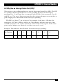
1
AUGUST 2000
IC133C-R2
IC187C
2-Port RS-232/422/485
PCI Host Adapter
CUSTOMER
SUPPORT
INFORMATION
Order toll-free in the U.S. 24 hours, 7 A.M. Monday to midnight Friday: 877-877-BBOX
FREE technical support, 24 hours a day, 7 days a week: Call 724-746-5500 or fax 724-746-0746
Mail order: Black Box Corporation, 1000 Park Drive, Lawrence, PA 15055-1018
Web site: www.blackbox.com • E-mail: [email protected]
FCC AND IC STATEMENTS
FEDERAL COMMUNICATIONS COMMISSION
AND
INDUSTRY CANADA
RADIO FREQUENCY INTERFERENCE STATEMENTS
This equipment generates, uses, and can radiate radio frequency energy and if not
installed and used properly, that is, in strict accordance with the manufacturer’s
instructions, may cause interference to radio communication. It has been tested
and found to comply with the limits for a Class A computing device in accordance
with the specifications in Subpart J of Part 15 of FCC rules, which are designed to
provide reasonable protection against such interference when the equipment is
operated in a commercial environment. Operation of this equipment in a
residential area is likely to cause interference, in which case the user at his own
expense will be required to take whatever measures may be necessary to correct
the interference.
Changes or modifications not expressly approved by the party responsible
for compliance could void the user’s authority to operate the equipment.
This digital apparatus does not exceed the Class A limits for radio noise emission from
digital apparatus set out in the Radio Interference Regulation of Industry Canada.
Le présent appareil numérique n’émet pas de bruits radioélectriques dépassant les limites
applicables aux appareils numériques de la classe A prescrites dans le Règlement sur le
brouillage radioélectrique publié par Industrie Canada.
1
2-PORT RS-232/422/485 PCI HOST ADAPTER
EUROPEAN UNION DECLARATION OF CONFORMITY
Products bearing the CE Label fulfill the requirements of the EMC directive
(89/336/EEC) and of the low-voltage directive (73/23/EEC) issued by the
European Commission.
To obey these directives, the following European standards must be met:
• EN55022 Class A - “Limits and methods of measurement of radio interference
characteristics of information technology equipment”
• EN50082-1 - “Electromagnetic compatibility - Generic immunity standard”
Part 1: Residential, commercial and light industry
• EN60950 (IEC950) - “Safety of information technology equipment, including
electrical business equipment”
Use high quality shielded cabling with this product to maintain compliance with
the EMC directive.
2
NOM STATEMENT
NORMAS OFICIALES MEXICANAS (NOM)
ELECTRICAL SAFETY STATEMENT
INSTRUCCIONES DE SEGURIDAD
1. Todas las instrucciones de seguridad y operación deberán ser leídas antes
de que el aparato eléctrico sea operado.
2. Las instrucciones de seguridad y operación deberán ser guardadas para
referencia futura.
3. Todas las advertencias en el aparato eléctrico y en sus instrucciones
de operación deben ser respetadas.
4. Todas las instrucciones de operación y uso deben ser seguidas.
5. El aparato eléctrico no deberá ser usado cerca del agua—por ejemplo,
cerca de la tina de baño, lavabo, sótano mojado o cerca de una alberca, etc.
6. El aparato eléctrico debe ser usado únicamente con carritos o pedestales que
sean recomendados por el fabricante.
7. El aparato eléctrico debe ser montado a la pared o al techo sólo como sea
recomendado por el fabricante.
8. Servicio—El usuario no debe intentar dar servicio al equipo eléctrico más allá
a lo descrito en las instrucciones de operación. Todo otro servicio deberá ser
referido a personal de servicio calificado.
9. El aparato eléctrico debe ser situado de tal manera que su posición no
interfiera su uso. La colocación del aparato eléctrico sobre una cama, sofá,
alfombra o superficie similar puede bloquea la ventilación, no se debe
colocar en libreros o gabinetes que impidan el flujo de aire por los orificios
de ventilación.
10. El equipo eléctrico deber ser situado fuera del alcance de fuentes de calor
como radiadores, registros de calor, estufas u otros aparatos (incluyendo
amplificadores) que producen calor.
11. El aparato eléctrico deberá ser connectado a una fuente de poder sólo del
tipo descrito en el instructivo de operación, o como se indique en el aparato.
3
2-PORT RS-232/422/485 PCI HOST ADAPTER
12. Precaución debe ser tomada de tal manera que la tierra fisica y la polarización
del equipo no sea eliminada.
13. Los cables de la fuente de poder deben ser guiados de tal manera que
no sean pisados ni pellizcados por objetos colocados sobre o contra ellos,
poniendo particular atención a los contactos y receptáculos donde salen
del aparato.
14. El equipo eléctrico debe ser limpiado únicamente de acuerdo a las
recomendaciones del fabricante.
15. En caso de existir, una antena externa deberá ser localizada lejos
de las lineas de energia.
16. El cable de corriente deberá ser desconectado del cuando el equipo
no sea usado por un largo periodo de tiempo.
17. Cuidado debe ser tomado de tal manera que objectos liquidos no sean
derramados sobre la cubierta u orificios de ventilación.
18. Servicio por personal calificado deberá ser provisto cuando:
A: El cable de poder o el contacto ha sido dañado; u
B: Objectos han caído o líquido ha sido derramado dentro del aparato; o
C: El aparato ha sido expuesto a la lluvia; o
D: El aparato parece no operar normalmente o muestra un cambio
en su desempeño; o
E: El aparato ha sido tirado o su cubierta ha sido dañada.
TRADEMARKS
The trademarks mentioned in this manual are acknowledged to be the property of the
trademark owners.
4
TABLE OF CONTENTS
CONTENTS
1. Specifications............................................................................................7
2. Introduction .............................................................................................8
2.1 Overview .............................................................................................8
2.2 What’s Included .................................................................................8
2.3 Factory Default Settings.....................................................................9
3. Card Setup................................................................................................10
3.1 RS-485 Enable Modes ........................................................................10
3.2 Address and IRQ Selection ...............................................................12
3.3 Line Termination...............................................................................12
3.4 Electrical Interface Selection ............................................................14
3.5 Clock Modes.......................................................................................15
3.6 Baud Rates and Divisors for the “Div 1” Mode ................................16
3.7 Baud Rates and Divisors for the “Div 2” Mode ................................18
4. Installation................................................................................................20
4.1 Setting Up the Operating System .....................................................20
4.1.1 Windows 3.1x ...........................................................................20
4.1.2 Windows 95/98 ........................................................................20
4.1.3 Windows NT .............................................................................21
4.1.4 DOS...........................................................................................21
4.1.5 Other Operating Systems ........................................................21
4.2 Installing the Hardware.....................................................................21
5. Troubleshooting ......................................................................................22
5.1 The Serial Utility Diskette ................................................................22
5.2 Calling Black Box..............................................................................23
5.3 Shipping and Packaging...................................................................23
Appendix A: Interrupt Handling ...............................................................24
A.1 The Purpose and Early History of Interrupts..................................24
A.2 Why Use an ISP? ................................................................................25
Appendix B: Connector Pinouts ................................................................26
B.1 RS-232.................................................................................................26
B.2 RS-422/485 ........................................................................................27
5
2-PORT RS-232/422/485 PCI HOST ADAPTER
CONTENTS (continued)
Appendix C: Electrical Interfaces...............................................................28
C.1 RS-232.................................................................................................28
C.2 RS-422.................................................................................................28
C.3 RS-485.................................................................................................29
Appendix D: Asynchronous Communications ..........................................30
Appendix E: Board Layout..........................................................................32
6
CHAPTER 1: Specificatiobns
1. Specifications
Communication Chip — IC133C-R2: 16550 UART (optionally, you can
remove this UART and install a 16950 UART for better performance);
IC187C: 16950 UART
Data Rate — IC133C-R2: Up to 460.8 kbps; IC187C: 460.8 kbps and above
Distance — Up to 4000 ft. (1219.2 m)
Number of Ports — (2) RS-232/422/485
Connectors — (2) DB9 male
Temperature — Operating: 32 to 122°F (0 to 50°C); Storage: -4 to +158°F
(-20 to +70°C)
Relative Humidity — 10 to 90%, noncondensing
MTBF — Greater than 150,000 hours
Power — +12 VDC @ 50 mA, -12 VDC @ 50 mA, +5 VDC @ 480 mA
Size — 4.2"H x 5"L (10.7 x 12.7 cm)
Weight — 1.3 lb. (0.6 kg)
7
2-PORT RS-232/422/485 PCI HOST ADAPTER
2. Introduction
2.1 Overview
The 2-Port RS-232/422/485 PCI Host Adapter is a two-channel PCI-bus serial I/O
adapter for PCs and compatibles that supports data rates up to 460.8 kbps. It has
two very versatile asynchronous serial ports: They are field-selectable as either
RS-232 ports (suitable for communication with modems, printers and plotters) or
RS-422/485 ports (suitable for industrial automation and control applications).
Configure both of the Adapter’s ports as RS-232 for standard serial COM-port
requirements. Choose the RS-422 mode for long-distance device connections up to
4000 ft. (1219.2 m) where noise immunity and high data integrity are essential.
Select RS-485 and capture data from multiple peripherals in a RS-485 multidrop
network. Up to 31 RS-485 devices can be connected to each port to automate your
data collection. You can even mix the ports in any of the interface combinations to
provide maximum flexibility to your application.
In both RS-232 and RS-422 modes, the card works seamlessly with the standard
operating-system serial driver. In RS-485 mode, our special auto-enable feature
allows the RS-485 ports to be viewed by the operating system as a COM port. This
allows the standard COM driver to be used for RS-485 communications. The onboard hardware automatically handles the RS-485 driver enable.
The IC133C-R2 adapter uses a 16550 UART. This chip features programmable
baud rates, data format, interrupt control and a 16-byte input and output FIFO.
You can replace the 16550 with a 16950 UART for even better performance. The
IC187C comes with the 16950 UART already installed.
2.2 What’s Included
The Adapter is shipped with the following items. If any of these items are missing
or damaged, contact the supplier.
• (1) 2-Port RS-232/422/485 Serial Host Adapter
• (2) 3.5” Serial Utility Diskettes
• This User Manual
8
CHAPTER2: Introduction
2.3 Factory Default Settings
The Adapter’s factory-default settings are as follows:
Table 2-1. Factory-Default Settings
Port #
Electrical Specification
Port 1
RS-232
Port 2
RS-232
For your reference, record installed Adapter settings below.
Table 2-2. Installed Adapter Settings
Port #
Electrical Specification
Port 1
Port 2
9
2-PORT RS-232/422/485 PCI HOST ADAPTER
3. Card Setup
NOTE
In all cases J1x refers to settings for the first port and J2x refer
to settings for the second port.
3.1 RS-485 Enable Modes
RS-485 is ideal for multidrop or network environments. RS-485 requires a tri-state
driver that will allow the electrical presence of the driver to be removed from the
line. The driver is in a tri-state or high-impedance condition when this occurs.
Only one driver may be active at a time, and the other driver(s) must be tri-stated.
The output modem control signal Request To Send (RTS) is typically used to
control the state of the driver. Some communication-software packages refer to
RS-485 as RTS enable or RTS block mode transfer.
One of the unique features of the Adapter is the ability to be RS-485 compatible
without the need for special software or drivers. This ability is especially useful in
Windows, Windows NT, and OS/2 environments, where the lower-level I/O
control is abstracted from the application program. This ability means that the user
can effectively use the Adapter in a RS-485 application with existing (i.e. standard
RS-232) software drivers.
Headers J1B and J2B are used to control the RS-485 mode functions for the
driver circuit. The selections are “RTS” enable (marked “RT”) or “Auto” enable
(marked “AT”). The “Auto” enable feature automatically enables/disables the
RS-485 interface. The “RTS” mode uses the “RTS” modem-control signal to enable
the RS-485 interface and provides backward compatibility with existing software
products.
Position 3 (marked “NE”) of J1B and J2B is used to control the RS-485
enable/disable functions for the receiver circuit and determine the state of the
RS-422/485 driver. The RS-485 “Echo” is the result of connecting the receiver
inputs to the transmitter outputs. Every time a character is transmitted, it is also
received. This can be beneficial if the software can handle echoing (i.e. using
received characters to throttle the transmitter) or it can confuse the system if the
software does not. To select the “No Echo” mode, select the position marked “NE.”
For RS422/530/449 compatibility, remove the jumpers at J1B and J2B.
10
CHAPTER 3: Card Setup
Examples on the following pages describe all of the valid settings for J1B
and J2B.
Interface Mode Examples J1D – J4D
AT
RT
NE
Figure 3-1. Headers J1B and J2B set for RS-422.
AT
RT
NE
Figure 3-2. Headers J1B and J2B set for RS-485 “Auto” with “No Echo.”
AT
RT
NE
Figure 3-3. Headers J1B and J2B set for RS-485 “Auto” with “Echo.”
11
2-PORT RS-232/422/485 PCI HOST ADAPTER
AT
RT
NE
Figure 3-4. Headers J1B and J2B set for RS-485 “RTS” with “No Echo.”
AT
RT
NE
Figure 3-5. Headers J1B and J2B set for RS-485 “RTS” with “Echo.”
3.2 Address and IRQ selection
The Adapter is automatically assigned I/O addresses and IRQs by your
motherboard BIOS. Only the I/O address may be modified by the user.
Adding or removing other hardware may change the assignment of I/O
addresses and IRQs.
3.3 Line Termination
Typically, each end of the RS-485 bus must have line terminating resistors
(RS-422 terminates at the receive end only). A 120-ohm resistor is across each
RS-530/422/485 input in addition to a 1K ohm pull-up/pull-down combination
that biases the receiver inputs. Headers J1A and J2A allow the user to customize
this interface to their specific requirements. Each jumper position corresponds to
a specific portion of the interface. If multiple Adapters are configured in a RS-485
network, only the boards on each end should have jumpers T, P & P ON. Refer to
the following table for each position’s operation:
12
CHAPTER 3: Card Setup
Table 3-1. Jumper Operation
Name
Function
P
Adds or removes the 1K-ohm pull-down resistor in the
RS-422/RS-485 receiver circuit (Receive data only).
T
Adds or removes the 120-ohm termination.
L
Connects the TX+ to RX+ for RS-485 two-wire operation.
L
Connects the TX- to RX- for RS-485 two-wire operation.
P
P
T
L
L
Figure 3-6. Headers J1A and J2A, which control line termination.
13
2-PORT RS-232/422/485 PCI HOST ADAPTER
3.4 Electrical Interface Selection
Port 2
RS-232
RS-422
E2
E3
E4
Port 2
Port 1
RS-232
E1
RS-232
RS-422/485
RS-422
RS-232
RS-422
E4
RS-232
RS-232
E3
RS-422
RS-422
E2
Port 1
RS-232
E1
RS-422
Each port on the Adapter has the ability to be used in either RS-232 or
RS-422/485 mode. This is selectable via four 24 pin DIP-shunts at E1-E4. Please
use the following illustration to aid in the configuration of your electrical interface.
RS-232 and RS-422/485
Figure 3-7. Headers E1 through E4, which control electrical-interface
selection.
14
CHAPTER 3: Card Setup
3.5 Clock Modes
The Adapter employs a clocking option that allows you to select from “divide by 4,”
“divide by 2,” and “divide by 1” clocking modes. These modes are selected at
Headers J1C through J4C.
To select the baud rates commonly associated with COM ports (for example,
2400, 4800, 9600, and 19,200 bps, and so on up to 115.2 kbps), place the jumper in
the “divide by 4” mode (marked DIV4).
DIV1
DIV2
DIV4
Figure 3-8. Clocking mode “divide by 4.”
To double these rates, so that the Adapter can communicate at up to a
maximum rate of 230.4 kbps, place the jumper in the “divide by 2” position
(marked DIV2).
DIV1
DIV2
DIV4
Figure 3-9. Clocking mode “divide by 2.”
15
2-PORT RS-232/422/485 PCI HOST ADAPTER
To enable the Adapter to reach its maximum possible data rate, 460.8 Kbps,
place the jumper in the “divide by 1” position (marked DIV1).
DIV1
DIV2
DIV4
Figure 3-10. Clocking mode “divide by 1.”
3.6 Baud Rates and Divisors for the “Div1” Mode
The following table shows some common data rates and the rates you should
choose to match them if you’re using the Adapter in the “Div1” mode.
Table 3-2. Baud Rates for the “Div 1” Mode
16
For this Data Rate
Choose this Data Rate
1200 bps
300 bps
2400 bps
600 bps
4800 bps
1200 bps
9600 bps
2400 bps
19.2 kbps
4800 bps
57.6 kbps
14.4 kbps
115.2 kbps
28.8 kbps
230.4 kbps
57.6 kbps
460.8 kbps
115.2 kbps
CHAPTER 3: Card Setup
If your communications package allows the use of baud-rate divisors, choose the
appropriate divisor from the following table:
Table 3-3. Divisors for the “Div 1” Mode
For this Data Rate
Choose this Divisor
1200 bps
384
2400 bps
192
4800 bps
96
9600 bps
48
19.2 kbps
24
38.4 kbps
12
57.6 kbps
8
115.2 kbps
4
230.4 kbps
2
460.8 kbps
1
17
2-PORT RS-232/422/485 PCI HOST ADAPTER
3.7 Baud Rates and Divisors for the “Div2” mode
The following table shows some common data rates and the rates you should
choose to match them if you’re using the adapter in the “Div2” mode.
Table 3-4. Baud Rates for the “Div 2” Mode
18
For this Data Rate
Choose this Baud Rate
1200 bps
600 bps
2400 bps
1200 bps
4800 bps
2400 bps
9600 bps
4800 bps
19.2 kbps
9600 bps
38.4 kbps
19.2 kbps
57.6 kbps
28.8 kbps
115.2 kbps
57.6 kbps
230.4 kbps
115.2 kbps
CHAPTER 3: Card Setup
Table 3-5. Divisors for the “Div 2” Mode
For this Data Rate
Choose this Divisor
1200 bps
192
2400 bps
96
4800 bps
48
9600 bps
24
19.2 kbps
12
38.4 kbps
8
57.6 kbps
4
115.2 kbps
2
230.4 kbps
1
19
2-PORT RS-232/422/485 PCI HOST ADAPTER
4. Installation
IMPORTANT
You MUST set up the operating system BEFORE you physically install
the Card.
4.1 Setting Up the Operating System
If you are installing the PCI adapter in DOS, OS/2®, or QNX, please refer to
the appropriate directory on one of the Serial Utilities Disks for instructions.
4.1.1 WINDOWS 3.1X
Refer to the Win3x.hlp file in the \Win31 directory on Disk 1 of the Serial Utilities
software.
4.1.2 WINDOWS 95/98 USERS
If you are installing the PCI card in Windows 95/98, run setup on disk two of the
Serial Utilities Diskettes before installing the card. Power down the computer and
install the adapter. The resources are automatically configured for the PCI card.
Refer to the appropriate help file in the Black Box folder located in the Start,
Programs menu for changing those resources.
Selecting the PCI COM Number in Windows 95
When installing a PCI Serial Adapter in Windows 95 or 98, the default COM
numbers assigned to the two ports will be COM5 and COM6 if those numbers are
not already assigned. If they are assigned to other devices, the next available COM
numbers will be assigned to the ports.
To change the two ports so that Windows assigns them to COM3 and COM4:
1. Double-click the “Systems” icon in the control panel or right-click on
“My Computer” and choose “Properties,” which will bring you to
“System Properties.”
2. Choose the “Device Manager” tab and double-click on the “Multi-Function
Adapter” heading. This will show all the information concerning the PCI
Serial Adapter.
3. Choose the “Resources” tab, which will show all resources assigned to the PCI
Adapter. Uncheck the “Use Automatic Settings” box. Three input/output
(I/O) ranges will be listed. The first I/O range is for the PCI bus and should
not be changed. The second and third I/O ranges are the ones that need to
be changed in order to have those ports set to COM3 and COM4.
4. Double-click on the second I/O range, which will allow you to change the
address. Highlight the entire I/O range and type 03e8–03ef for COM3. Click
OK. Windows will inform you that you have made modifications that may
affect other devices. Click OK.
20
CHAPTER 4: Installation
5. Next, double-click on the third I/O range. Highlight the entire I/O range
and type 02e8–02ef for COM4. Again, Windows will inform you that you have
made modifications that may affect other devices. Click OK.
Following these steps will change the COM: number assignments on the first
two ports to COM3 and COM4.
4.1.3 WINDOWS NT
If you are installing a PCI card in Windows NT, run setup on disk two of the
Serial Utilities Diskettes before installing the card. After the software installation
is complete, power down the computer, install the card, then power up. Since
resource allocation is automatic, the installation is now complete.
4.1.4 DOS
Refer to the Readme.txt file found in the \DOS directory on Disk 1 of the Serial
Utilities software.
4.1.5 OTHER OPERATING SYSTEMS
Refer to the appropriate directory on Disk 1 of the Serial Utilities software.
4.2 Installing the Hardware
The Adapter has several jumper straps for each port that must be set for proper
operation (see Chapter 3). Once you’ve done this, and have set up your operating
system (see Section 4.1), take these steps to install the Adapter in any of your PC’s
PCI expansion slots:
1. Turn off PC power. Disconnect the power cord.
2. Remove the PC case cover.
3. Locate an available PCI slot and remove the blank metal slot cover.
4. Gently insert the Adapter into the slot. Make sure that the adapter is seated
properly.
5. Replace the screw.
6. Replace the cover.
7. Connect the power cord.
The Adapter should now be ready for continuous operation.
21
2-PORT RS-232/422/485 PCI HOST ADAPTER
5. Troubleshooting
5.1 The Serial Utility Diskette
The Adapter comes with a Serial Utility Diskette that has diagnostic software on it.
We recommend that you always use this software first when you troubleshoot
problems, because it can help resolve most common problems related to software
and operating-system incompatibilities without requiring you to call Technical
Support.
1. Make sure the Adapter is securely installed in a motherboard slot.
2. Use the supplied diskette and User Manual to verify that the Adapter is
configured correctly. The supplied diskette contains the diagnostic programs
“FindPCI,” “SSD” (for DOS), and “WINSSD” (for Windows NT, 3.1, or 95),
which will verify if an adapter is configured properly. First, run the “FindPCI”
utility and record the base I/O addresses and the IRQ assignments, these will
be needed for SSD. Next, run the “SSD” diagnostic program (for DOS) or the
“WINSSD” program (for Windows). Refer to the \dos\diag\diag.txt file on the
supplied diskette for detailed instructions on using “SSD.”
The Serial Utility Diskette might also contain README-style text files. You can
consult these for information about issues that might have arisen since this manual
was written, and for application-specific information.
22
CHAPTER 5: Troubleshooting
5.2 Calling Black Box
If you determine that the Adapter is malfunctioning, do not attempt to alter or repair
it. It contains no user-serviceable parts. Contact Black Box Technical Support at
724-746-5500.
Before you do, make a record of the history of the problem. We will be able to
provide more efficient and accurate assistance if you have a complete description,
including:
• current Adapter settings;
• the nature and duration of the problem;
• when the problem occurs;
• the components involved in the problem (make and model of PC, other cards
installed in it, the cables you’re using, etc.);
• any particular application that, when used, appears to create the problem or
make it worse;
• the results of any testing you’ve already done.
If possible, please also have the adapter installed in a computer ready to run
diagnostics when you call.
5.3 Shipping and Packaging
If you need to transport or ship your Adapter:
• Package it carefully. We recommend that you use the original container.
• If you are returning the Adapter, make sure you include everything you
received with it.
Before you ship, contact Black Box to get a Return Authorization (RA) number.
23
2-PORT RS-232/422/485 PCI HOST ADAPTER
Appendix A: Interrupt Handling
A.1 The Purpose and Early History of Interrupts
A good analogy of a PC interrupt would be the phone ringing. The phone “bell” is
a request for us to stop what we are currently doing and take up another task
(speak to the person on the other end of the line). This is the same process the PC
uses to alert the CPU that a task must be preformed. The CPU upon receiving an
interrupt makes a record of what the processor was doing at the time and stores
this information on the “stack”; this allows the processor to resume its predefined
duties after the interrupt is handled, exactly where it left off. Every main sub-system
in the PC has its own interrupt, frequently called an IRQ (short for Interrupt
ReQuest).
In these early days of PCs, the ability to share IRQs was an important feature for
any add-in I/O card. Consider that in the IBM XT the available IRQs were IRQ0
through IRQ7. Of these interrupts only IRQ2-5 and IRQ7 were actually available
for use. This made the IRQ a very valuable system resource. To make the
maximum use of these system resources, an IRQ-sharing circuit was devised that
allowed more than one port to use a selected IRQ. This worked fine as a hardware
solution but presented the software designer with a challenge to identify the source
of the interrupt. The software designer frequently used a technique referred to as
“round-robin polling.” This method required the interrupt service routine to “poll”
or interrogate each UART as to its interrupt-pending status. This method of
polling was sufficient for use with slower-speed communications, but as modems
increased their throughput abilities this method of servicing shared IRQs became
inefficient.
24
APPENDIX A: Interrupt Handling
A.2 Why Use an Interrupt Status Port (ISP)?
The answer to the polling inefficiency was the Interrupt Status Port (ISP). The ISP
is a read-only 8-bit register that sets a corresponding bit when an interrupt is
pending. Port 1’s interrupt line corresponds with bit D0 of the status port, Port 2’s
with D1, etc. The use of this port means that the software designer now only has to
poll a single port to determine if an interrupt is pending.
The ISP is at “base+7” on each port. For example, if the base = 280 hex, the
status port = 287 hex, 28F hex, and so on. The Adapter will allow any one of the
available locations to be read to obtain the value in the status register. Both status
ports on the Adapter are identical, so either one can be read.
Example: This indicates that Channel 2 has an interrupt pending:
Bit Position:
7
6
5
4
3
2
1
0
Value Read:
0
0
0
0
0
0
1
0
25
2-PORT RS-232/422/485 PCI HOST ADAPTER
Appendix B: Connector Pinouts
B.1 RS-232
Table B-1. Pinout of Connector Set to RS-232
Abbreviation
Name
Pin #
Mode
TD
Transmit Data
3
Output
RTS
Request To Send
7
Output
DTR
Data Term Ready
4
Output
GND
Ground
5
RD
Receive Data
2
Input
DCD
Data Carrier Detect
1
Input
DSR
Data Set Ready
6
Input
CTS
Clear To Send
8
Input
RI
Ring Indicator
9
Input
NOTE
These pin assignments meet the EIA/TIA/ANSI-574 standard for RS-232
DTE pinning on DB9 connectors.
26
APPENDIX B: Connector Pinouts
B.2 RS-422/485
Table A-2. Pinout of Connector Set to RS-422/485
Abbreviation
Name
Pin #
Mode
GND
Ground
5
TX +
Transmit Data Positive
4
Output
TX-
Transmit Data Negative
3
Output
RTS+
Request To Send Positive
6
Output
RTS-
Request To Send Negative
7
Output
RX+
Receive Data Positive
1
Input
RX-
Receive Data Negative
2
Input
CTS+
Clear To Send Positive
9
Input
CTS-
Clear To Send Negative
8
Input
27
2-PORT RS-232/422/485 PCI HOST ADAPTER
Appendix C: Electrical Interfaces
C.1 RS-232
Quite possibly the most widely used communication standard is RS-232. This
implementation has been defined and revised several times and is often referred
to as EIA/TIA-232.
The IBM PC/AT computer defined the RS-232 port on a 9-pin D-subminiature
connector, and subsequently the EIA/TIA approved this implementation as the
EIA/TIA-574 standard. This standard is defined as the 9-Position Non-Synchronous
Interface between Data Terminal Equipment and Data Circuit-Terminating
Equipment Employing Serial Binary Data Interchange. Both implementations are
in widespread use and are referred to as RS-232 in this document.
RS-232 is capable of operating at data rates up to 20 kbps at distances less than
50 ft. The absolute maximum data rate may vary due to line conditions and cable
lengths. RS-232 is a single-ended or unbalanced interface, meaning that a single
electrical signal is compared to a common signal (ground) to determine binary
logic states. The RS-232 and the EIA/TIA-574 specification define two types of
interface circuits: Data Terminal Equipment (DTE) and Data Circuit-Terminating
Equipment (DCE). The Adapter is a DTE device.
C.2 RS-422
The RS-422 specification defines the electrical characteristics of balanced-voltage
digital interface circuits. RS-422 is a differential interface that defines voltage levels
and driver/receiver electrical specifications.
On a differential interface, logic levels are defined by the difference in voltage
between a pair of outputs or inputs. In contrast, a single-ended interface, for
example RS-232, defines the logic levels as the difference in voltage between a
single signal and a common ground connection.
Differential interfaces are typically more immune to noise or voltage spikes that
may occur on the communication lines. Differential interfaces also have greater
drive capabilities that allow for longer cable lengths. RS-422 is rated up to
10 megabits per second and can have cabling 4000 feet (1219.2 m) long. RS-422
also defines driver and receiver electrical characteristics that will allow 1 driver and
up to 32 receivers on the line at once. RS-422 signal levels range from 0 to +5 volts.
RS-422 does not define a physical connector.
28
APPENDIX C: Asynchronous Communications
C.3 RS-485
RS-485 is backward-compatible with RS-422; however, it is optimized for partyline
or multidrop applications. The output of the RS-422/485 driver is capable of being
Active (enabled) or Tristate (disabled). This capability allows multiple ports to be
connected in a multidrop bus and selectively polled.
RS-485 allows cable lengths up to 4000 feet (1219.2 m) and data rates up to
10 megabits per second. The signal levels for RS-485 are the same as those defined
by RS-422.
RS-485 has electrical characteristics that allow for 32 drivers and 32 receivers to
be connected to one line. This interface is ideal for multidrop or network
environments. RS-485’s tristate (not dual-state) driver will allow the electrical
presence of the driver to be removed from the line. Only one driver may be active
at a time, and the other driver(s) must be tristated.
RS-485 can be cabled in two ways: two-wire and four-wire mode. Two-wire mode
does not allow for full-duplex communication, so data be transferred in only one
direction at a time. For half-duplex operation, the two transmit pins should be
connected to the two receive pins (Tx+ to Rx+ and Tx to Rx). Four-wire mode
allows full-duplex data transfers.
RS-485 does not define a connector pinout, a physical connector, or a set of
modem control signals.
29
2-PORT RS-232/422/485 PCI HOST ADAPTER
Appendix D:
Asynchronous Communication
In serial data communication, individual bits of a character are transmitted
consecutively to a receiver that assembles the bits back into a character. Data rate,
error checking, handshaking, and character framing (start/stop bits) are predefined and must correspond at both the transmitting and receiving ends.
Asynchronous communications is the standard means of serial data
communication for PC compatibles and PS/2 computers. The original PC
was equipped with a communication or COM port that was designed around an
8250 Universal Asynchronous Receiver Transmitter (UART). This device allows
asynchronous serial data to be transferred through a simple and straightforward
programming interface. A start bit, followed by a pre-defined number of data bits
(5, 6, 7, or 8), defines character boundaries for asynchronous communications.
The end of the character is defined by the transmission of a pre-defined number
of stop bits (usually 1, 1.5, or 2).
Idle State
of
Line
5 to 8 Data Bits
Odd
Even
or
Unused
Remain Idle
or
Next Start Bit
1
Parity
Bit
0
1
1.5
2
Stop Bits
Figure D-1. Bit diagram for asynchronous communication.
An extra bit used for error detection is often appended before the stop bits.
This special bit is called the parity bit. Parity is a simple method of determining
if a data bit has been lost or corrupted during transmission. There are several
methods for implementing a parity check to guard against data corruption.
Common methods are called (E)ven Parity or (O)dd Parity. Sometimes parity
is not used to detect errors on the data stream. This is refereed to as (N)o parity.
30
APPENDIX D: Asynchronous Communication
Because each bit in asynchronous communications is sent consecutively, it is easy
to generalize asynchronous communications by stating that each character is
wrapped (framed) by pre-defined bits to mark the beginning and end of the serial
transmission of the character. The data rate and communication parameters for
asynchronous communications have to be the same at both the transmitting and
receiving ends. The communication parameters are baud rate, parity, number of
data bits per character, and stop bits (usually listed in that order, like this:
9600,N,8,1).
31
2-PORT RS-232/422/485 PCI HOST ADAPTER
Appendix E: Board Layout
U1 GD75232 R2
C2
C4 J1B
R8
R29
J2B
C12
R30 J1C
J2C
HEADER24PINW
E2
J2
E5
R12 U4 75174
R13
P P T L L
U7 16550 PLCC
E6
U9
C7
R14
U4 75175 R27
R15
R28
R19 R23
E3
C8
Port 2
HEADER24PINW
DIV1
DIV2
DIV4
R18 R22 R26
R3 R5 R7
U2 GD75232
RS422
16550 PLCC
R31
C15
• JxC - CLOCK DIV •
DIV1= DIVIDE BY 1
DIV2= DIVIDE BY 2
DIV4= DIVIDE BY 4
PCI9050
PORT1= J1x
PORT2= J2x
U5 93CS46
HEADER24PINW
C14
Port 2
R17 R21 R25
R11
P P T L L
RS232
C11
R16 R20 R24 XC9536-7201
Port 1
C3 R4 R5 R8 R9 R10
J2A
E4
MADE IN USA
C6
• JxA JUMPER SETTINGS •
P= PULL UP/DOWN ENABLE
T= TERMINATION ENABLE
L= CONNECT RX TO TX
C9
C16
U8
Figure E-1. Board layout.
32
C13
+
C5
DIV1
DIV2
DIV4
E1
Port 1
RS422
HEADER24PINW
J1A
Port 2
C10
J1
RS232
Port 1
Y1
U6
• JxB JUMPER SETTINGS •
RS422 - REMOVE ALL JUMPERS
RS485 - AT= AUTO ENABLE
RS485 - RT= RTS ENABLE
RS485 - NE= NO ECHO
AT
RT
NE
R1
AT
RT
NE
7201
C1
P1
C17
NOTES
NOTES
© Copyright 2000. Black Box Corporation. All rights reserved.
1000 Park Drive • Lawrence, PA 15055-1018 • 724-746-5500 • Fax 724-746-0746