1
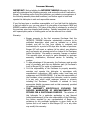
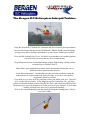
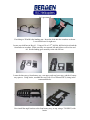
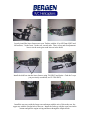
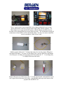
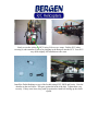
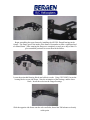
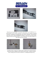
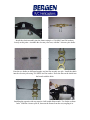
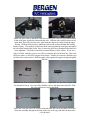
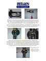
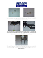
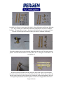
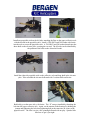
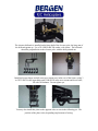
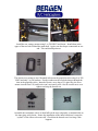
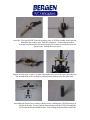
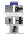
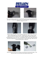
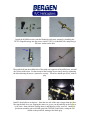
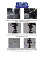
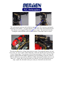
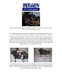
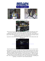
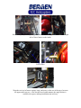
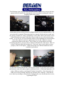
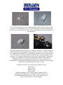
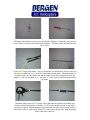
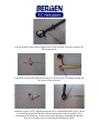
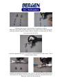
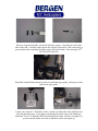
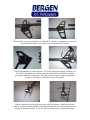
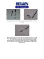
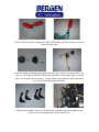
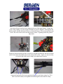
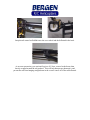
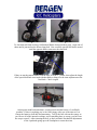
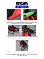
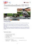
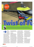
WARNING!
The radio controlled model helicopter built from this kit is not a toy and
is not meant for children. It is a flying machine capable of causing
property damage and serious bodily harm to both the
operator/assembler and/or spectator if not built and operated
correctly and responsibly. Rotating components, especially the main
rotor blades, are an ever-present danger.
Model helicopters operate differently than model cars and airplanes.
Helicopters by their nature are not positively stable, meaning that even
if properly assembled and adjusted, helicopters will not recover from
an unwanted flight attitude, nor will they hold any particular
orientation without constant control inputs from the pilot.
IT IS YOUR EXCLUSIVE RESPONSIBILITY TO PROPERLY
BUILD, MAINTAIN AND OPERATE THIS HELICOPTER. Bergen
R/C Helicopters has spent considerable time making this
product reliable and easy to build, but only the operator can
insure that it is safe. Because the safe operation of this
helicopter is beyond the control of the Manufacturer and
distributor, the owner/operator assumes all risk of use.
Construction Manual
Acknowledgments
Bergen R/C Helicopters wishes to thank our friends and
customers for their continuing support during the
development of the Intrepid Helicopter.
The Instruction Manual and illustrations were completed
with the input of numerous customers and staff. We wish to
recognize Gary Wright, who had been the test pilot and
helicopter guru in its early years. We would also like to
recognize Mike DeMetz for his continuous support and
knowledge in electronics and maintenance.
Staff
Chris Bergen; Chief Executive Officer
Larry Bergen; Chief Design Engineer and General Manager
Maryann Pratt; Office Management
Mike Bergen; Programmer, Engineer
Larry Mihills; Machinist
Malorie Zastrow; Test Pilot/Engineer
Bergen R/C Helicopters LLC
1101 Follett Drive
Cassopolis, MI 49031
Voice: (269) 445-2060
Fax: (269) 445-2250
Web: www.bergenrc.com
Email: [email protected]
Introduction
The first of its kind, interchangeable modular engineered helicopter
to accommodate the beginner to a FAI expert…
An idea in 1994 to manufacture an interchangeable, modular
helicopter, led to the research and development in 1995. Focusing
on quality, engineering details, and price, a prototype was produced.
After extensive test flights and fine-tuning, the INTREPID
HELICOPTER is now what you see today. The first of its kind,
strength combined with simplicity for easy maintenance and flying.
Although beginners can successfully build and fly their INTREPID, the
process can be made significantly easier with the help of an
experienced modeler and instructor pilot. We recommend that all
beginners join the Academy of Model Aeronautics (AMA). The AMA is
a non-profit organization that provides services for modelers. The
AMA can help you locate a model aircraft club in your area with an
instructor pilot (you can also check with your local hobby shop).
Membership benefits include a monthly magazine and liability
insurance. Many flying clubs require an AMA modeler’s license to
operate a model on their flying field. For more information on the
AMA contact:
Academy of Model Aeronautics
5151 East Memorial Drive
Muncie, IN 47302
Phone: (317) 287-1256
Consumer Warranty
IMPORTANT! Before building the INTREPID TURBINE Helicopter kit, read
and fully understand the following warranty, and review the entire Construction
Manual. By building and/or flying this helicopter you indicate your acceptance of
the following warranty terms and conditions, and further agree to build and
operate this helicopter in safe and responsible manner.
If you find any term or condition unacceptable, or if you feel that this helicopter
is just not suited to you, you may return it to your place of purchase in NEW and
UNUSED condition within thirty (30) days of the date of purchase for a refund of
the purchase price less shipping and handling. Partially assembled kits, and kits
with opened parts packs or missing parts can not be returned for a refund.
Warranty:
1. Bergen warrants to the first consumer Purchaser that the
INTREPID TURBINE helicopter substantially conforms to its
published description when used as intended as a hobby
product, and will be free from defects in materials and
workmanship for a period of 90 days after the date of purchase.
Bergen R/C will repair or replace (at his option) any defective
part, and supply any missing part at no charge to the Purchaser
within this period. We make no warranty, express or implied.
This warranty does not apply to parts damaged by improper
assembly, modification, abnormal service or handling, or
crashes.
2. To take advantage of this warranty, the Purchaser must provide
proof of purchase, and ship any defective part (at Purchaser’s
cost) to Bergen R/C for repair or replacement.
3. It is the responsibility of the Purchaser to properly assemble,
maintain and operate this helicopter in accordance with
manufacture’s instructions, AMA safety codes, local laws and
ordinances, and COMMON SENSE. It is also the responsibility of
the Purchaser, when operating this helicopter, never to operate
it in any way, which might endanger persons or property
including the Purchaser.
Purchaser is advised to carry
appropriate liability insurance such as that commonly provided
to modelers by the AMA.
4. THIS
WARRANTY SPECIFICALLY EXCLUDES THE
IMPLIED WARRANTIES OF MERCHANTABILITY AND
FITNESS FOR A PARTICULAR PURPOSE. The selection of
this helicopter for a particular application or use (beyond
hobby/entertainment) is the sole responsibility of the Purchaser.
Any advice supplied by any representative of Bergen R/C
pertaining to any particular application is given freely as an
opinion and is not meant to bind Bergen R/C or in any other
way modify this warranty.
1. Not withstanding the paragraph above, this warranty is in
addition to whatever implied warranties may be granted to the
Purchaser by law. To the extent permitted by law, all implied
warranties, including the warranties of merchantability and
fitness for a particular purpose are limited to a period of (1)
year from the date of purchase. Some states do not allow
limitations on how long an implied warranty last, so the above
limitation may not apply.
2. This warranty shall be the sole and exclusive remedy available
to the Purchaser. Correction of defects, in the manner and for
the period of time specified above, shall constitute complete
fulfillment of all liabilities and responsibilities of Bergen R/C to
the Purchaser, and shall constitute full satisfaction of all claims,
whether based on contract, negligence, strict liability or
otherwise. Bergen R/C shall not be liable for any cost or
expenses incurred in; the replacement of any effective or nonconforming parts, and IN NO EVENT SHALL BERGEN R/C
BE LIABLE FOR INCIDENTAL OR CONSEQUENTIAL
DAMAGES, OR ANY DAMAGES DUE TO THE USE OR
INABILITY TO USE THIS PRODUCT. Bergen R/C shall not
be liable, or in any way responsible, for any damages related to
modifications, repairs, attempted repairs, or crashes. IN NO
EVENT SHALL BERGEN R/C’s OBLIGATIONS TO THE
PURCHASER EXCEED THE ORIGINAL PURCHASE PRICE
PAID BY THE PURCHASER.
3. Some states do not allow exclusion of incidental or
consequential damages, so the above exclusion may not apply.
This warranty gives the Purchaser specific legal rights. The
Purchaser may also have other rights, which vary, from state to
state.
4. No modification or amendment to this warranty will be effective
unless reduced to writing and signed by an authorized
representative of Bergen R/C Management.
If you do not understand any aspect of this warranty, you may contact
Bergen R/C Helicopters for clarification. IF YOU DO NOT AGREE WITH ANY
ASPECT OF THIS WARRANTY, RETURN THE UNASSEMBLED
HELICOPTER TO YOUR MANUFACTURER FOR A REFUND.
Bergen R/C Helicopters believes that information contained within its published
materials is accurate as of the date of publication, and is not responsible for
inadvertent errors or omissions. Bergen R/C reserves the right to make changes
and improvements in its products without notice.
Chris and Larry Bergen
Bergen R/C Helicopters
The Bergen R/C Helicopters Intrepid Turbine.
Using the Wren MW 54 Turbine Gas Generator and Wren Gearbox, proven mechanics
based on The Bergen Intrepid Gasser EB, 800 mm V-Blades, Paddles and Tail blades,
giving you the best in aerobatic performance, to date, from a Turbine powered Heli.
We would like to thank Gary Travis. His belief in our mechanics as a turbine platform
has so far been proven beyond any of our wildest dreams.
Greg Alderman has been a tremendous amount of help, flight testing, cajoling, and the
occasional trip to Golden Corral ☺.
Both of these guys, and numerous others can be found online at Runryder.com or
Helifreak.com for questions and concerns.
A note about this manual. Considerable time and care has been taken creating this
manual, however, improvements can always be made. If you have some positive
suggestions, please let us know.
If you need to see a close up of any particular picture, just double click on it. That will
give you the full size picture. A few things can also be found on the CD. All of the
pictures used in this manual, pictures from IRCHA 2005, and videos from IRCHA 2005.
I hope these give you some inspiration to fly the snot out of your Turbine!! It is certainly
capable, and large brass ones can be purchased separately…
There is also a troubleshooting chart that may help during the learning phase, if this is
your first Turbine.
You will need a few items to operate and maintain your Bergen Intrepid Turbine. Here
are some of the things we recommend.
Powermax Fuel starting gas available from Coleman. You can usually find it in camping/
outdoor stores. Wren recommends Turbine oil such as this, mixed 4 oz to a gallon of
Kerosene.
Duralite Lithium Ion Battery systems. They have a special deal just for the Bergen
Turbine. We like the Flat packs.
BVM UAT. The Ultimate Air Trap, available from Bob Violet Models. Essentially a
header tank, keeps bubbles from getting to the Turbine.
Also the Trigger for the Powermax starting gas, available from BVM, makes filling your
turbine quick and easy. A container and pump will be needed for the kerosene, too. You
will also need 4 ea 12” long servo extension wires. Use high quality ones, with proper
connectors.
We also highly recommend a good set of hardened allen drivers such as found at Rick’s
R/C, Rave’s Designs, or your local hobby shop. The standard allen wrenches are just too
soft for our purposes and may cause screw heads to strip out.
Blue loctite #242 is also used throughout the build of your Bergen Intrepid Turbine.
A flybar lock, designed for the Intrepid line, is also available from us.
Let’s get started!
First thing we’ll build is the landing gear. Insert the skids into the crossbars as shown.
Leave them loose for right now.
Locate your skid bars in Bag # 1. Using a #30 or 1/8th” drill bit, drill the holes in both the
front and rear crossbars. Make sure they are centered left and right as well as fore and
aft. Set the landing gear assembly to the side for now.
Locate the three trays, front battery tray, rear upper, and rear lower tray, and the 6 battery
tray spacers. Using loctite, assemble the trays with 18 ea 3X8mm FHCS, sitting in the
countersunk holes.
Now install the angle bracket to the front battery tray, on top, using a 3X8 SHCS, with
loctite.
Insert the turbine mount heatsink in the corresponding oval in the lower frames. Note the
heatsink sits on the outside of the frames. You can tell the outside of the frames by the
countersunk hole at the bottom.
Using 4 ea 3X6 SHCS and loctite, from the inside of the frames, secure the heatsink.
Locate the front canopy standoffs (18mm long) and 3X8 low head screws, install them in
the front holes in the lower frames, using loctite, insuring you put the standoffs on the
outside of the frames. You will see a deeper countersink on one end of the standoff.
Install this countersink away from the frames. This is to help align the canopy
thumbscrew when installing the canopy.
Loosely install the lower frames onto your Turbine with the 10 ea 4X12mm SHCS and
4M washers, 3 in the front, 2 in the rear, on each side. There is fore and aft adjustment
here to set the main gear mesh later on in the build.
Install the skid bars into the lower frames using 3X8 FHCS and loctite. Grab the 3 trays
you previously assembled, and 12 3X8 SHCS,
Install the rear trays with the longer one on bottom with the trio of slits to the rear, the
upper one with the circular hole to the rear. Install the fwd tray with the cross bars on the
bottom and pull the engine wiring and hoses through the elliptical hole.
Now’s a good a time as any to install the receiver battery under the lower rear tray,
square pack shown on the left, flat pack on the right, along with the regulator. Use
Velcro strips or tye wraps to hold it all in place, with the cutouts provided in the tray.
Feed the wires up through the large cutout in the lower tray. We recommend securing all
connections in some fashion, such as heatshrink tubing. You may also want to install the
receiver switch now, while access is easy.
Find the propane bottle and “T” fitting in the engine kit, also the propane filling hose,
with Quick disconnect. You won’t use the filling valve, just the yellow hose and fittings.
Fit a short piece of tubing on the propane bottle and connect the “T”. Your fittings may
be slightly different on this bottle.
Install a short piece of yellow hose to the “T” on the propane bottle, and install the rest on
the Trigger for the Powermax Fuel bottle. Attach double sided tape to the bottom of the
propane tank and BVM UAT.
Using a #6 drill bit, locate and install the quick disconnect for the gas bottle in this
approximate location.
Install the BVM UAT and propane bottle in the rear trays, securing them with the doublesided tape. Connect the yellow hose to the Quick disconnect. Attach the landing gear to
the skid bars using 4 ea 3X16 SHCS and 3M locknuts.
After securing the skids to the cross bars, drill a small pilot hole in the boss located on the
inside of the crossbar and install the 3X8 self tapping screws.
Using double sided tape or Velcro, install the fuel and gas valves on the front tray. Cut
the green tubing from the Turbine, leaving sufficient length to reach, and insert into the
gas valve. Insert the rest into the opposite side of the valve and route to the rear. The gas
valve has a needle adjustment,
Give it 4 turns out and lock into place.
Turbine to valve
Valve to pump,
note direction of
arrow on valves.
The clear 3mm tubing is the fuel line (Kerosene) and is connected to the fuel valve in the
same manner, cutting it to fit. Then connect a short piece to the fuel pump and secure the
pump onto the tray in this location. Use the Wren Turbine instruction manual as a guide
to plumbing instructions.
Route the lubrication hose to the bottom of the gearbox, and install on the nipple fitting.
The green sheath is a heat shield, but keep it as far from the exhaust as possible.
Neatly secure the wiring and ECU using Velcro or tye wraps. Pad the ECU when
securing it, and remember to allow for plugging in the data port into the ECU. Your ECU
may differ slightly, but installation is the same.
Install the Delrin Bushings on top of the fan hub using 4X12 SHCS and loctite. Note the
chamfer on the steel insert. This goes against the head of the bolt. Tighten these very
securely. If they come loose, they push up against the clutch bell locking up the clutch
system.
Begin assembling the upper frames by installing the 6X12X4 flanged bearings in the
frames. The flange goes to the inside of the frames. Remember to make a right hand and
a left hand frame. After ensuring the flanges are completely seated, put a drop of thin CA
glue around the perimeter to secure them in the frames.
Locate the main shaft bearing blocks and collective axles. Using 3X35 SHCS, locate the
bearing blocks on one side frame. Note the orientation of the bearings, and the lower
block. Install the axles into the flanged bearings.
Slide the opposite side frame onto the axles and bolts, thread the 3M locknuts on loosely
at this point.
Gather the gyro mounting plate, 3 hole blocks, and hardware, 6 ea 3X8 SHCS and 1 ea
3X8 FlatHead Cap Screw (FHCS). Install the 3 hole blocks loosely, noting the orientation
of the holes. Install the gyro mounting plate on top of the 3 hole blocks. Note the FHCS
in the front, on top. Go back and tighten the side bolts. These blocks are made of delrin,
therefore loctite is not needed. However, if you feel the need, you can put a drop of CA
glue on the bolts when installing.
Assemble the drive system next. Slide the clutch w/shaft into the clutch bell, add the
triple bearing block, sliding the bottom bearing onto the pinion. Install the retaining
collar, securing with 3X3 setscrews and loctite. Everything should spin freely.
Install the clutch assembly into the frames using 4 ea 3X8 SHCS and 3M washers,
loosely at this point. Assemble the elevator yoke next, with the 2 elevator yoke shafts.
Note the two shafts are different lengths; one has flats on only one side. Install the shafts
into the elevator yoke using 3X4 SHCS and 3m washer. Draw the flats on the shafts into
the broach with the bolts.
Installing the opposite side may require a ball ended allen wrench. Use loctite on these
bolts. Slide the elevator yoke in, between the frames from the rear, angling it in.
You want to have the long shaft sticking out on the right side of the frames.
Assemble the main shaft drive system, starting with the main gear. Install the Auto Hub
in from the bottom side of the gear; the longer end of the hub is the top. Secure with 3X8
Low Head Cap Screws, using loctite. Now is a good time to lube the one-way bearings
in the auto hub. Use a light oil such as 3 in 1, or automatic transmission fluid.
One end of the main shaft gets the collar; note that this bolt is a 4-40 standard bolt, not
metric. Hold the main gear in place and slide the main shaft through it and into the
bottom bearing block.
Install one split collar on the shaft, under the elevator yoke. Note the ring on the bottom
of the collar goes against the bottom bearing face. Slide the other collar in place on the
main shaft, above the elevator yoke, again with the ring on the collar facing the upper
bearing. With the shaft in place, tighten the frame bolts and nuts holding the bearing
blocks in place. Now pull up on the main shaft, seating against the main gear and tighten
the bolt on the bottom split collar. Here is where the good set of hardened allen drivers is
most important. The heads of the bolts are turned down to fit the collars. If you use a
soft set of allen wrenches, you are very likely to strip the head of the bolt out. This is the
ONE area where we DO NOT suggest using loctite. It makes it even more difficult to get
the bolts loose when needed. Push the upper collar against the upper bearing and tighten
the bolt.
Assemble the front transmission next. Slide the output shaft into the delrin coupler until
the thru holes line up. One end of the shaft has a divot; the other has a thru hole. Slide
the cross pin thru the coupler and shaft.
Secure the cross pin with a 3X4 setscrew threaded into the rear of the shaft, with loctite.
Slide this assembly through the bearing in the rear of the cage and slide the brass tube
over the shaft.
Install the tail drive pinion on the shaft, and push the shaft all the way forward into the
front bearing. Look through the threaded hole in the pinion, looking for the divot in the
shaft. The 2 holes in the pinion are slightly offset. If one doesn’t line up fore and aft,
rotate the pinion and try the other hole. Secure the pinion on the shaft with a 3X4
setscrew into the divot on the shaft, with loctite. A second setscrew is not necessary, and
may cause a clearance problem with the screws on the main gear. You should not be able
to move the shaft in and out after tightening the setscrew, but it should spin freely.
Remove the rear bolt from the lower main shaft bearing block. Install the front
transmission into the frames from the rear. Note the “ears” on the front of the cage match
the tongue on the lower main shaft bearing block. Reinstall the bolt securing the front of
the cage, loosely. You can set the tail pinion mesh at this point by pushing down on the
cage at this point. You will want very little backlash with no tightness while spinning the
main gear. When you’re happy with the mesh tighten the thru bolt securely.
Now install 4 ea 3X8
SHCS, with loctite,
securing the rear of the
cage to the frames.
Start assembling the control system with the single and triple bellcranks, 2 ea long balls
and 2 ea short balls. Loctite into place.
The triple bellcrank is installed on the left side, with the 3X8 SHCS, 3M washer, and
loctite, fitting it onto the front collective axle. The single bellcrank is fitted on the right
side, on the same axle, with a 3X8 SHCS, washer, and loctite.
The short balls on the two bellcranks should point in the same direction, and the whole
assembly should spin freely. If not, check that the flanged bearings are seated in the
frames all the way.
Assemble the collective arms (popsickle sticks), aileron bellcranks and elevator bellcrank
(“X” arm). Install 10 ea short balls with loctite, and install 8 ea 5X8X2.5 flanged
bearings. The popsickle sticks get 1 bearing ea; the bellcranks get 2 ea, inner and outer.
Note the left and right aileron bell cranks, (the balls are mounted differently).
Insert the jamnuts into the inner bearings, then thread the bolt with 3M washer into the
jamnut. The aileron bellcranks use a 3X16 SHCS; the “X” arm gets a 3X20 SHCS. Do
not tighten yet.
Install the aileron bellcranks onto the popsickle sticks with loctite by threading the
remainder of the bolt into the arm, just forward of the bearing. This is where you set the
tension on the bearings in the bellcranks, by holding the jamnut and tightening the bolt,
then tightening the jamnut and bolt together to secure it to the popsickle stick. Don’t
forget the loctite.
Install one popsickle stick on the left side, matching the flats on the upper collective axle
with the broach in the popsickle stick. Install a 3X8 SHCS and 3M washer with loctite
into the axle to secure the popsickle stick. A 3X4 SHCS and 3M washer threads into the
short shaft on the elevator yoke, securing the rear end. The left side can be identified by
the position of the balls on the aileron bell crank.
Install the right side popsickle stick on the collective axle and long shaft in the elevator
yoke. Also assemble the elevator bellcrank with 2 ea short balls and loctite.
Both balls go on the same side, with loctite. The “X” arm get installed by threading the
bolt into the upper collective axle. Again, set the tension on the bearings by holding the
jamnut and tightening the bolt, then tightening both at the same time to secure to the
popsickle stick. The idea is to get a free spinning bellcrank with no play. Spend a little
time here to get it just right.
The elevator bellcrank is installed on the long shaft of the elevator yoke, the long arm of
the bellcrank points up. Use a 3X4 SHCS and 3M washer, with loctite. The bellcrank
should be perpendicular to the elevator yoke, with the balls pointed out.
Install the boom clamps and tail rotor servo mount next, in the rear of the frames, using 3
ea 3X35 SHCS in the upper holes and 3X40 SHCS in the servo mount and lower holes,
all with 3M locknuts. Do not tighten yet.
You may also install this plate on the opposite side, as seen in the following pic. The
position of the plate varies, depending on placement of wiring.
Install the rear canopy mounts using 2 ea 3X8 SHCS and loctite. Install them in the
upper of the two holes behind the main shaft. Again, note the deeper countersink on one
end. This end should point out.
The aileron servo mount is next. Mounted in between the popsickle sticks using 4 ea 3X8
SHCS and only 2 ea 3M washers. Put the washers on the rear bolts that go through the
slots in the popsickle sticks. Instead of loctite, use a drop of CA glue here, the servo
mount is made from G10, and loctite won’t necessarily stick. Also be careful not to over
tighten and strip the threads out.
Assemble the swashplate with 4 ea short balls on the outer ring and 4 ea medium balls on
the inner ring, using loctite. Ensure the installation of the inner balls doesn’t cause the
“eyeball” in the center to become stiff. Check that the threads aren’t too long if this
happens.
Install swashplate onto main shaft and snap the elevator yoke ball links onto the balls.
The washout unit is next, start with the washout arms, installing the washout links (pork
chops) by inserting the pin through both pieces and securing with a 3X3 setscrew and
loctite.
Your kit is supplied with two different sets of pork chops. They are handed, left and right.
The difference is which side snaps onto the ball on the swashplate. We suggest using the
left handed ones initially. Install 2 ea 3X7X3 flanged bearings in each arm.
Insert the 3X16 special SHCS into the bearings, place a 3M brass washer on the bolt and
thread into the washout unit. Note the orientation. Set the tension on these
bearings by tightening the bolt and securing with a setscrew threaded in from the
opposite side, locking the two in place.
Repeat for other side. Loctite 2 ea short balls on the inner side of the arms, and slide onto
the mainshaft above the swashplate, and snap the porkchops on to the inner balls.
Assembling the head is next, starting with the seesaw, installing the 4X10X4 bearings in
the end of the tube. Do not confuse these bearings with the 3X10X4 bearing that
will be installed in the headblock later. The bearings should sit flush in the tube.
Now use the 3X10X3 bearings, inserting a 3X8 SHCS and placing a 3M brass washer
over the threads, and a drop of loctite. Inserting the seesaw tube into the head
(noting the orientation of the slots on the end), thread the bolt into the middle of
the seesaw tube. Draw it up tight (without stripping the threads). You will find
that the bearing is not flush in the headblock. Tap the head of the bolt, pushing
the bearing below flush. This will aid in installing the bolt and bearing on the
opposite side, which you should do now, using the same procedure.
Now tap the assembly back in, centering it in the head. The seesaw should tilt back and
forth freely. Install the seesaw endcaps, noting the orientation. Install a 3X3
setscrew in the inner hole, which seats into the end of the slot on the tube.
The endcaps should also be flush with the end of the seesaw. Loctite the 3X5 panhead
screws securing the bearings into the headblock. Be careful not to get loctite in
the bearing itself. Install 2 ea short balls in the seesaw endcaps outer hole, with
loctite.
Insert the headaxle into the head. Put grease in the gap between the axle and headblock,
then slide 2 ea dampening o’rings on each side onto the headaxle. Make sure they are
lubricated with grease as well.
Slide the dampening shims onto the headaxle against the O’rings. This is where you
adjust the dampening to suit your tastes. The thick shim (.040) is required, and we
suggest at least the .015 shim as well. For tighter dampening, add the .008 shim, for
looser dampening, either remove the .015 and add the .008, or remove them both entirely.
Slide the circlip onto the axle and push into place using the blade grip. Make sure the
clip seats into the groove on the axle.
Slide the blade grip onto the axle and grease the ball cage for the thrust bearings. Note
that one of the races has a larger inner diameter than the other.
Insert this race into the blade grip first, groove facing out. Then insert the greased
ballcage, open side in.
Then install the race with the smaller inner diameter, groove facing in. Using loctite,
install the 5X16 SHCS and 5X10X2 spacer washer, repeating for the opposite blade grip,
and tightening both bolts at the same time with 2 allen wrenches. German torque is
preferable here, “gut an tight”.
Thread the 3X16 SHCS “pinch bolts” in, loosely for now, and install the head button
using 3X10 SHCS and loctite.
Install the bell/hiller mixers onto the bladegrip pitch arms, starting by installing the
3X7X3 flanged bearings into the mixers, insert a 3X12 w/6 shoulder bolt, and placing a
3M brass washer on the bolt.
Thread the bolt into the middle hole of the pitch arm, opposite of the milled area, and add
the 3M nut with loctite. Set the tension in the bearings as previously done by tightening
the bolt and using the nut as a jamnut for security. The mixer should spin freely, with no
play.
Install 2 short balls on each mixer. Note that one side of the arm is longer than the other.
Moving the balls in or out, flipping the arms over, gives you adjustability in the flybar to
cyclic ratio. Start with these settings shown, and adjust to suit to your feel. Install the
pitch arm assembly onto each blade grip with 3X6 SHCS and loctite, noting the flat
milled on the pitch arm, mating to the blade grip.
Slide the head onto the mainshaft, matching the jesus bolt hole in the head and mainshaft.
Install the 3X20 SHCS loosely for now.
The washout hub pins slide up into the slots in the headblock. Install the 3X16 SHCS
pinchbolts, with loctite, tightening them a little at a time, alternating sides. Now go back,
loctite, and tighten the jesus bolt.
Locate your flybar, 2 flybar arms, 2 ea 4m special washers, and 2 ea 3X4 setscrews.
Slide the flybar through the seesaw bearings, centering it as close as possible. Install the
washers, then the flybar arms, pushing the flybar arms up against the seesaw bearings.
Loosely install the setscrews into the end of the flybar arms.
Measure the flybar from the arm to the end, checking that both sides are exactly the same,
then tighten the setscrews lightly. The flybar arms should be parallel with each other as
sighted down the flybar. When your happy with the measurements and alignment,
remove, loctite, and reinstall the setscrews, one at a time.
Thread the flybar paddles onto the end of the flybar, on far enough so that you cannot see
any threads through the setscrew hole in the paddle. Measure from the flybar arm to the
paddle, ensuring both sides are exactly the same. Note direction of rotation.
Level the paddles with each other and the flybar arms, sighting across the head. Sight
from both sides, when happy with the measurement and alignment; install the setscrews,
with loctite, securing the paddles to the flybar.
Start servo installation by putting the rubber grommets in place on the servo ears.
Depending on where the servo is located and how it’s mounted you either a; install the
servo mount tabs into the G10 plate or frame,
And install the brass eyelets in the rubber grommets from the bottom,
Then thread the screws into the servo mount plate. Or b; the servo mount tab is installed
in the rubber grommets of the servo,
Then the screws are installed through the mount plate or frame, into the plastic servo
tabs. As an alternative, or for Futaba servo users (the Futaba screws are too small in dia.)
you can use 2.5X10mm SHCS and 2.5mm washers.
Elevator servo mounts here, outside of the upper frames. Aileron mounts here, on top of
the servo mount. Don’t worry about the servo wheels just yet. These pics are for servo
placement only.
Install your favorite Gyro here, the tail servo here, using the plastic servo mount tabs.
Note the orientation of the servo, with the wheel forward.
As an alternative, you can mount the tail servo and servo mount on the opposite side.
Make up the 2 pushrods w/ ballinks from the collective bellcranks (triple and single), to
the collective arms (popsickle sticks). They are 70mm long from center to center. Adjust
the length of the elevator yoke “A” arm to 67mm long, from the edge of the arm to center
of hole.
Make up the 2 aileron bellcrank to swashplate rods, 57mm from center to center. Make
the 2 washout arms to flybar arm rods 46mm from center to center.
The rods from the seesaw to the bell mixer arms use 2 ea 3X12 setscrews and require
trimming of the ballinks. Cut approximately ¼” off of the ends, then thread them onto
the setscrews for a length of 29mm from center to center. The pitch rods from the
swashplate to the bell hiller mixer are next and are 97mm from center to center.
The aileron pushrods are 105mm from center to center. The pushrods from the elevator
servo to the “X” arm are done a little differently. Make the forward rod 121mm long, the
aft one 124mm long. The geometry of the elevator push pull is a little off center, and
requires slightly different lengths of pushrods to prevent binding at extremes of throw.
This has shown not to present any difficulty in flight, through all aerobatics that we can
throw at it. Again, don’t worry about the servo wheels; we’ll get to them later on in
setup. Ignore the fuel tanks in the pics as they are from later on in the build.
The last set of pushrods that are needed are from the “X” arm to the elevator bellcrank.
They are 70mm from center to center.
The ballinks used in the Bergen Intrepid Turbine kits are the famed Rocket City Links.
As far as we know they are superior to anything else out there and will give long life if
installed and adjusted properly. They do, however, typically require reaming to get the
most satisfactory performance from them. There are a few commercial reaming tools
available, such as the JR tool, or you can make your own by using an old ball, scarred up
with a set of side cutters, and spun inside the ballink. Be careful, go slowly until you get
a feel for how much material to take off. The link should fall under it’s own weight when
snapped onto a ball, but should have no slop.
Place the upper frames on to the lowers by locating the clutch on the delrin bushings
installed on the fan hub. Make sure all wires and hoses are free and not pinched under the
frames. Locate the frame spacers and 10 ea 3X40 SHCS. There are 5 threaded, 26mm
spacers, and 10 unthreaded, 29mm spacers.
Threaded,
Unthreaded,
Bolt
Start in the rear, on one side.
And work your way forward. This is where leaving the Turbine mount bolts loose allow
you to move the frames back and forth to line up the frame spacers. Finish up by
installing the other 5 frame spacers and 3X40 SHCS on the other side. Now go back and
remove each 3X40 SHCS one at a time, apply loctite and reinstall bolt. (Note the elevator
pushrods and servo wheel removed for access)
Gap between clutch and fan hub should be even on both sides, viewed from the side and
from the rear.
Sight through the frames at the clutch alignment. Here is where you set your gear mesh
and alignment of your drive train. Move the Turbine and triple bearing block fore and aft
together, to get a minimum of backlash with no tight spots on the main gear. The whole
clutch drive assembly should be perfectly vertical as well A few extra minutes here can
make a huge difference in how vibration free your Bergen Turbine is. When your happy
with the results, go back and tighten the Turbine mount bolts and triple bearing block
bolts. Now go back and remove each bolt, one at a time, applying loctite, reinstalling and
tightening. Use Red RTV on the Turbine mount bolts.
Insert the plastic servo mount tabs into your collective servo and bolt it to the collective
servo plate. Notice the servo is behind the plate, and the shaft is to the rear.
Install the collective plate with servo onto the front tray, attaching it to the angle and the
upper frames with 2 ea 3X8 SHCS and loctite.
Make up the collective servo to triple bellcrank pushrods with ballinks. They are 94mm
long from center of hole to center of hole.
Now is a good time to clean up the wiring installation and plumbing. You will probably
need servo extensions to reach the receiver in the rear of the heli. Use heat shrink to
secure the connections. This was necessary to prevent interference from the ECU and
RPM sensor in the front of the turbine. A neat and clean installation will also make for a
safe and reliable Turbine helicopter. Bundle up wiring and secure with tye-wraps or
Velcro. Where wiring may contact the edges of frames, install fuel tubing to prevent
chafing
Route wiring and plumbing through the center front of the upper frames and down right
side of lower frames on the inside.
Velcro straps.
Wrap the receiver in foam or sponge wrap, and secure to the rear of the trays, between
the upper and lower tray. Also note the base loaded antenna, the angle bracket is
available on request, making installation neat and easy.
The following is the setup we use for JR radio systems. Futaba users can copy the hole
pattern from a JR wheel after centering the servos and wheels, marking the center or
straight up point on the wheel.
At this point you need to have the servos plugged into the receiver and powered up. All
servos need to be centered. This means trims are centered, all sub trims are zeroed, and
any mixing is turned off. Using a straightedge of some kind, make a line from the center
of the bellcrank to the center of the servo wheel, in this case we will use the elevator
system. As you can see, we have turned the wheel so the straightedge travels through the
3 hole sides and the 6 packs are equally spaced on the side. Mark the rearmost,
outermost two holes on the wheel. This is where you will install the servo balls.
Concerning JR wheels, you may notice a number on the backside of the wheel. There are
at least 5 different wheels that we know of. If you can’t get a certain wheel to center
properly, rotate it 180 degrees. If that doesn’t help try a different numbered wheel,
available from Horizon.
Do the same with the Aileron and Collective servo wheels. If you can’t get it centered
the first time, rotate 180, and try again, try different wheels. A little time spent here will
make a difference on how your Intrepid Turbine feels and flies. Don’t forget the tail
rudder servo wheel, marking either the top or bottom, after centering. Center the tail
servo either by switching to normal mode or plugging the servo directly into the receiver,
bypassing the Gyro.
Once you have all the servo wheels marked, install the hardware into the wheel. Each
one gets 2 ea 2X10m Philips screw, 2 ea 5X2m ball, and 4 ea 2m nuts. Slide the ball
onto the screw, thread a nut on to hold it in place, then thread the screw into the wheel at
the marked hole.
Thread the remaining nut onto the screw, securing it with loctite. Install the completed
wheel onto the servo, again making sure the radio is on and servo is centered. If using
servos with a metal output shaft, we recommend securing the servo screw with loctite as
well. The rudder servo wheel only gets one ball and screw set, top or bottom as your
preference. Now snap the links on from each servo to its first bellcrank. When set up
properly you should have 0 degrees of pitch with the collective stick at half, the
swashplate will be level fore and aft, and side to side. All arms will be level,
perpendicular, or at 90 degrees depending on its application, with the obvious exception
of the elevator system from the servo to the “X” arm.
Set the travel limits in your radio to these settings as a start;
Elevator 85%
Aileron 115%
Collective 100%
Throttle 100%
Rudder (depending on Gyro, in this instance, Futaba 401) 80%
Gain (again depending on Gyro, Futaba 401) HH 85%, normal 75%
Exponential (personal preference) try 20% on Ail and ELE to start.
Check servo directions for correct responses.
Working on the tail drive system, start off with the “dogbone”. Install the cross pin and
secure with a 3X4 setscrew from inside the dogbone. Use blue loctite and make sure the
pin is secure.
Locate the 2 Torque Tube shafts. They’re aluminum, not carbon fiber, and you will see a
silver dot on either end. Cut 1 inch off of both ends of both shafts. When the shafts are
anodized, some of it gets in the end and the inside is now the wrong diameter for our
purposes. Now cut one shaft 16 ¼ “, the other 17” long. Square and clean up the ends of
the shafts.
Install the long section of TT (Torque Tube) shaft onto the gearbox input shaft, and
install a collar at this location. Thread 1 ea. 3X3 Setscrew into one hole in the collar,
securing it in place. Plug the bearing carrier shaft into the other end, securing it with a
collar and 1 setscrew, then put the shorter TT shaft on the opposite side, again securing it
with a collar and 1 setscrew.
Complete the TT drive train by inserting the “dogbone” into the TT shaft, securing it with
a collar and 1 setscrew. Using a #50 drill bit, go back to each collar, picking one
threaded hole on each, drill through the TT shaft into the underlying shaft, in effect
drilling a dimple for the setscrew to set into, securing the whole assembly from any
possibility of slipping. Install a setscrew in each location that you just drilled, using blue
loctite. Also install setscrews in the third and final hole in each collar, using loctite, then
remove and reinstall the first setscrew, using loctite.
The completed assembly is quite long, be careful not to bend anything.
Slide the horizontal fin clamp onto the tail boom, note the holes in the boom are to the
rear. Lubricate the o’rings on the bearing carrier, and slide the whole assembly into the
tail boom.
Line up the holes in the gearbox with the holes in the tail boom, and secure with the 3X4
SHCS using loctite.
Find all the tail pitch bellcrank parts in bag 10A. Insert one 3X7X3 Flanged bearing and
the spacer in the pivot point.
Install the opposite 3X7X3 flanged bearing and 3X16 w6M shoulder SHCS. Place a brass
3m washer on the bolt and thread the bolt into the bracket on the tail gearbox. Note
orientation of the delrin cup. Set the tension on the bearing by tightening the bolt until
there is no free play, but not so tight that the bearing gets notchy.
When you’re happy with the adjustment, install the 3M locknut as a jam nut onto the bolt.
Hold the bolt in place while installing the locknut. Check the tension as it may have
moved slightly with the installation of the nut. DO NOT adjust the bolt at this time, first
loosen the nut, then adjust the bolt, and retighten the nut. Do this as many times as
needed to get a smooth operating bellcrank with no free play.
Install a medium ball onto the bellcrank, with loctite. Slide the tail pitch slider onto the
output shaft, at the same time inserting the ball into the delrin cup.
Locate the HD tail rotor hub and install it with 1, yes that is 1 ea, 3X4 setscrew, using
loctite. Make sure the setscrew seats in the divot on the output shaft.
Tail blade grips are next; Note the order of installation as follows;
Blade grip with bearings installed, 10mm dia. spacer washer, thrust washer w/large ID,
ball cage (remember to grease), thrust washer w/ small ID, 3m washer and 3X6 SHCS.
Use loctite on the 3X6 SHCS.
Repeat for opposite blade grip. You will note a slight amount of in and out play. This is
designed in and is normal.
Install the 4M shoulder bolt into the eyelet. This is a slip fit; the eyelet should rotate on
the shoulder bolt. Being careful to not get loctite in the eyelet, thread the bolt into the
blade grip. Repeat for other blade grip.
There are 2 special ball links, just for the tail rotor system. You will note a rib on the
sides of the link. Carefully remove these ribs with an X-acto knife. This is necessary to
prevent them from contacting the blade grips at full travel limits. Now trim appx 1/8th”
off of the end of the link.
Thread the trimmed links onto the eyelets on each blade grip equally, and snap on to the
balls on the pitch slider.
Locate your 110 mm V-Tail blades. Place a washer on either side of the tail blade and
slide into the blade grip. If it is tight, try deburring the inside edge of the blade grip.
Install the 3X19 w/11 shoulder SHCS tail bolt and 3m locknut. Do not over tighten, as
you do want the blades to be able to find their center when spun up.
Note orientation of Tail Blade, leading edge up and forward. Repeat for opposite tail
blade.
Locate your boom supports and threaded ends. You can identify the boom supports by
the threads on the inside. These are aluminum as well, not Carbon Fiber.
Glue the ends in with JB weld, ensuring the ends are parallel with each other. Let dry
overnight. Attach one end to the horizontal fin mount using a 3X35 SHCS and 3M nut.
Don’t tighten just yet.
Horizontal fin is next, secured with 2 ea 3X8 SHCS. Do not over tighten as you can strip
out the delrin fin mount. Use a drop of CA on the threads as a loctite.
Vertical fin mounting is a little different. Use 2 sets of the boom clamps, inserting 4 ea
3X35 SHCS through the fin, sliding one boom clamp half over the bolts vertically,
placing this assembly on the boom. Note the rear most clamp is right up against the
Gearbox. This helps to clamp the boom to the gearbox.
Slide the other half over the bolts and secure with 3M locknuts. Make sure the fin is
lined up vertically with the gearbox when tightening the nuts. It is not necessary to close
the gap of the boom clamps. If you do, you may run the risk of cracking the clamps.
Start the Tail pushrod assembly with the endcaps, inserting a 3X20 SHCS into the cap,
threading a 3M locknut to secure, then installing a ball link onto the bolt. Repeat for
other end cap.
.
The tail pushrod IS made from Carbon Fiber, and requires the end caps to be JB welded
on. Do not be tempted to CA or epoxy them. You must also cut the pushrod to length,
32 ½” will get you close enough to be able to adjust any minor differences with the
threaded ball links. Set the whole tail assembly aside for now to let the JB weld dry.
Prop it up somewhere to keep the ends in place. Air pressure inside the tube will try to
push the ends off.
Collect all the fuel system components. Start off by drilling a #6 hole into the very center
of the fuel bottle caps.
Insert the double end fitting in through the top and secure with the nut on the inside. Cut
2 pieces of fuel tubing; Install the clunk on one end and over the nipple in the cap on the
other. Secure both ends with zip ties. Clean all debris from inside the tanks, and install
the caps with fuel tubing onto the bottles.
Find the 4 tank saddles. Insert a 3X16 SHCS into each and mount the 4 saddles to the
frames with a 3M locknut on the inside of the frames.
Using either 2 sided Velcro or tye-wraps fed through the slots in the frames, secure the
fuel bottles to the tank saddles.
When satisfied with the position of the bottles, mark a point at the rear of the bottle, on
top for the vent. Drill a #21 hole and thread the single fitting with gasket into the hole,
securing with JB weld. Again, make sure to remove any debris from inside the fuel
bottles.
To secure the bottle in position with Velcro, use a piece of adhesive Velcro on the bottle
and wrap the self sticking Velcro over top of it. Do this under both strips, front and back.
Feed the fuel tubing through the large hole in the top of the tank saddle, attaching it to the
cap on one end and down through the frames at the back.
At this point you will need a “T” fitting for the fuel lines feeding from the bottles. Locate
at the rear as shown. Make these two fuel lines the exact same length.
Cut a piece of fuel tubing to fit between the “T” and the UAT. It does not matter which
nipple you attach the feed line to.
The other fitting will be used as the fueling line, and as such will need the stopper
supplied with the UAT. This prevents air from getting sucked into the UAT. A fueling
dot can also be used and mounted to the frames, if desired. Now add the vent hoses,
attached to the fittings on top of the rear of the bottles, feeding down through the frames.
Insert the tail boom into the boom clamps in the rear of the upper frames. Wiggle the
boom while pushing it in, also turn the tail blades to get the “dogbone” lined up with the
delrin coupler. Pushes the boom all the way forward, as far as it’ll go, then pull the boom
back 1 mm. This removes the rearward pressure of the TT pushing on the tail gearbox
input shaft.
Rotate the boom assembly until the vertical fin is straight up and down and the tail output
shaft is horizontal, then tighten the 6 boom clamp bolts evenly. Again, it is not necessary
to close the gap of the boom clamps, just tighten them securely.
Secure the front end of the boom supports to the lower rear frames using 2 ea 3X10
SHCS and 3M locknuts, then tighten the bolt through the horizontal fin clamp.
Snap the tail control rod ballink on to the servo wheel and the bellcrank in the back.
As an extra precaution, you can install a piece of Velcro, secured to the boom, then
loosely wrapped around the tail pushrod. This will help dampen any harmonics, and
prevent the rod from hanging straight down in the event it comes off of the tail bellcrank.
Install the 800 mm V-Blades using 4X25 SHCS w/18m shoulder and 4m locknuts.
Install the blades tight enough that they will not fall under their own weight if the heli is
turned on it’s side and shaken. Also ensure they are approximately the same tightness.
Note the direction of rotation, keeping the sticker on top let’s you know they’re in
correctly.
Check your pitch and throttle curves in your radio, for setup purposes, use a straight
linear line from 0 to 100. Do not setup any curve just yet. Also check for, and 0 out, any
sub trims. Inhibit any mixing that may be on by default.
Install the flybar lock or level the flybar by sight. Install a pitch gauge on the blade and
sight across the horizontal openings to the flybar. At mid stick on collective you should
read 0 degrees of pitch.
At full stick you should be able to get at least 10 degrees, low stick should give at least
-10 degrees. Different radios may differ on travel limits, adjust accordingly.
If you aren’t getting the +-10 degrees, go back and check servo centering, bell cranks
straight up and down or perpendicular, popsickle sticks level at 0 degrees, washout arms
level, bell mixers level. Adjust pushrod lengths as necessary.
Check your swashplate travel. With the settings given previously, you should have full
travel without binding against the mainshaft. Check fore and aft,
As well as side to side. Full swashplate travel will give you 7 degrees of cyclic, which is
plenty for most any aerobatic maneuver.
Tail setup is similar, center the servo wheel with the gyro in non-heading hold, and adjust
the tail pushrod to center the tail pitch slider on the output shaft.
Now adjust the travel limits on the gyro to give full travel without binding. If using a
GY401, travel limit should be between 100 and 120 on the pot on the gyro. If not, you
may need to use a smaller servo wheel and/or move the ball in or out, on the tail pitch
bell crank. Whatever it takes to get between 100 and 120. Delay should be at 0 if using
the 9254 servo. If using the GY601, make sure it is in F3C mode, not 3D. When
trimming the heli, switch to non-heading hold and check for drift on the tail. To adjust,
DO NOT change the length of the pushrod, adjust the ball links from the tail pitch slider
to the tail blade grips instead, equally of course, and check tracking after any adjustments
are made. Now switch into heading hold, and you should be rock solid. Typical gain
settings for the 401 are 85 to 95%.
1
2
To check the tail blade tracking, fold both tail blades forward in their grips. Angle one of
them until it just touches the boom clamp bolt. Now carefully spin the tail blades around
until the opposite blade comes near the same bolt.
If they are not the same distance from the bolt, as in the 2nd picture, then adjust the length
of the special ball link associated with that blade to bring it to the same adjustment as the
first blade. Check it again.
At this point stand back and admire your hard work and the beauty of a well built
machine. If there is anything you’re not 100% happy with, now is the time to fix it.
Charge the batteries, both heli and transmitter. Test fly the heli with out the canopy so
you can see all of the internal workings, and if something does go wrong, you have one
less step to repeat!! After trimming the heli, go back and make mechanical adjustments
to the 4 pushrods going up to the swashplate to center the trims.
Canopy trimming can be done before or after painting. These pics are just a suggestion.
Keep in mind the need for cooling and air intake for the Turbine.
The bottom edge does require trimming as shown. The top is opened up around the main
shaft/swashplate area. Ensure the pushrods from the aileron bell cranks to the swashplate
clear the lip.
Fit the canopy to the heli. Mark where the standoffs are, and drill 1/8th hole in this
location. When you’re happy with the locations, drill the holes with a 5/16th drill. If you
spin the drill backwards, it is less likely to chip the paint. Install the rubber grommets
and secure with a drop of CA on the inside.
Secure the canopy to the heli with the supplied thumbscrews. Make sure they are secure
before flying each time. A canopy that falls off usually does so at the most inopportune
time, such as when hovering inverted, 2 feet off the ground!!
To fill your heli with kerosene, hook the hose from the pump to the fill hose going to the
UAT, filling until you see the fuel begin to come out of the vent lines. Remove the fill
hose and replug the fill line going to the UAT.
To fill the gas canister, plug the fitting into the quick disconnect and give 2 short bursts
into the canister. Do not be tempted to fill the canister, as it will only cause a large flame
out of the exhaust on startup. (Don’t ask how I know!!) 2 short bursts will normally give
at least 3 starts of the Turbine.
Your turbine has been test run on the bench. Your gearbox may also have been test run
and leak checked. Read through the instruction manual provided with the turbine from
Wren. It provides some very good insights into turbine operations. Your ECU also has
been reprogrammed with some slight differences as it comes from Wren. These are
changes that we have found help the turbine run through the first few hours with as little
difficulties as possible. After you have some time on the Turbine, give us a call for some
additional programming changes to enhance how your turbine runs.
Set your headspeed, using an optical tach, to between 1450 and 1550, in a hover. The
Intrepid Turbine typically hovers at 5-6 degrees of pitch as well. Set your pitch curve
accordingly.
Now for the strange part, the throttle curve. Once you understand that this Turbine is
probably the most powerful engine mounted in a model helicopter, you begin to see that a
normal throttle curve just won’t work. The lower part of the throttle curve is “normal”,
but from the hover point up, you will end up with a fairly flat line. I don’t mean flat to
the top, I mean flat across. In my case, my hover point is at 52 percent on my curve. My
high point is at 54 percent. That’s right, I only add 2 percent from a hover to full power.
My Idle up curve is a “V” curve with the same shallow or “flat” curve. In other words,
you’re throttle curve numbers will be something like 0, 25,52,53,54 in normal and
54,53,52,53,54 in idle up.
When trimming out the heli and setting your pitch and throttle curves, disable the rotary
knobs and or sliders that some radios use to give quick adjustments. They can cause the
ECU to require relearning after each flight. I went through many a frustration with this
problem, which quit as soon as I turned them off.
I hope that your build of the Bergen R/C Helicopters Intrepid Turbine has been
enjoyable, and that it will give many weekends of reliable and enjoyable flights.
As always, any questions or concerns, please call us at 269-445-2060, e-mail at
[email protected], or see us at your favorite fun fly.
If you are not a member of AMA, Academy of Model Aeronautics, we highly suggest
you join, if nothing else than for the insurance. We also highly suggest joining IRCHA,
which is the helicopter Special Interest Group (SIG) for AMA, and getting your Turbine
waiver paperwork. This requires 2 CD’s (Contest Directors) signatures, one of which
must be on the Turbine list. This shows that you have proven to be able to operate and
handle a high performance helicopter, and can operate a turbine safely.
Be safe, and have fun.
Chris and Larry Bergen
Bergen R/C Helicopters
.