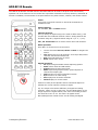
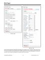
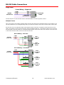
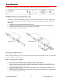
1
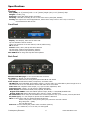
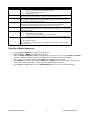
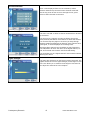
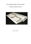
Product Manual 232-ATSC+SDI HDTV Tuner with HD-SDI September 10, 2014 Version 1.19 HD Processor Version 2.03 4355 Excel Pkwy, Suite 600, Addison, TX, 75001 Phone: 972-931-2728 • Toll-Free: 888-972-2728 • Fax: 972-931-2765 E-Mail: [email protected] • Website: www.crwww.com Table of Contents Overview ................................................................................................................................................................. 3 Specifications .......................................................................................................................................................... 4 Physical .................................................................................................................................................................. 4 Front Panel ............................................................................................................................................................. 4 Back Panel ............................................................................................................................................................. 4 Tuning ................................................................................................................................................................... 5 Captioning .............................................................................................................................................................. 5 Includes ................................................................................................................................................................. 5 Options .................................................................................................................................................................. 5 Trademarks ............................................................................................................................................................ 5 Quick Setup ............................................................................................................................................................. 6 Tuner Setup – Front-panel Quick Setup ..................................................................................................................... 6 Channel Tuning – On-Screen menus ......................................................................................................................... 6 Front Panel Setup ................................................................................................................................................... 7 Setup Menus .......................................................................................................................................................... 7 Front-Panel Button Sequences .................................................................................................................................. 8 Firmware Update .................................................................................................................................................... 9 Troubleshooting .................................................................................................................................................... 10 HD2-RC IR Remote ............................................................................................................................................... 12 Web Pages............................................................................................................................................................. 13 On-Screen Menus .................................................................................................................................................. 14 Main Menu ............................................................................................................................................................ 14 Channel Menus ...................................................................................................................................................... 14 Caption Menus ....................................................................................................................................................... 16 V-Chip Settings Menus ............................................................................................................................................ 16 Setup Menus ......................................................................................................................................................... 17 Pop-Up Menus ....................................................................................................................................................... 19 RS-232/Telnet Control Protocol ........................................................................................................................... 20 Control Commands ................................................................................................................................................. 21 Terminal Communication Commands ....................................................................................................................... 23 HD2-RC Remote Emulation ..................................................................................................................................... 23 Response Strings .................................................................................................................................................. 24 Response Strings ................................................................................................................................................... 24 Using USB as an RS-232 Port ............................................................................................................................... 25 RS-232 Cable Connections ................................................................................................................................... 26 Rack Mounting ...................................................................................................................................................... 27 RK2EZ Dual Rack Kit with Tie Bar Mounting .............................................................................................................. 27 RK1 Single Unit Rack Mount .................................................................................................................................... 27 RK2 – Locking Cases together ................................................................................................................................. 27 Safety Instructions ............................................................................................................................................... 28 Limited Warranty .................................................................................................................................................. 29 Contemporary Research 2 ATSC+SDI HDTV Tuner Overview The ATSC+SDI is the first HDTV Tuner that features an onboard HD-SDI port. A professional HDTV tuner, the ATSC+SDI is controllable via RS-232, IP, and IR commands. An onboard Web page enables remote Web control. A new menu-driven display simplifies setup, and a front-panel USB port makes firmware updates a snap. The new compact enclosure allows mounting of two tuners in a single rack space. The integral HD-SDI output allows inclusion of 708/608 captioning, choice of AES stereo or AC-3 audio, and scaled output set to a constant 1080i, 720p, or 480i resolution. A universal TV tuner, the ATSC+SDI can receive both analog and digital channels, in ATSC, NTSC, and clear QAM formats. Using an optional RF switcher, the tuner can switch between Antenna and Cable feeds. Tunes analog and digital channels in ATSC, NTSC, and clear QAM formats Always-active HD-SDI, Component, and composite video, as well as stereo, SPDIF coax and optical audio ports Dolby® 5.1 or PCM/Variable PCM digital audio formats for digital audio ports HD-SDI selectable to pass through Dolby 5.1 as AC-3 or decode to stereo AES audio Front-panel text and onscreen menus for tuner setup Web page for remote setup and control Supports dual Air/Cable tuning with optional RF-AB switch 608 (SD-SDI) and 708 (HD-SDI) closed captioning embedded in SDI output Internal scaler displays all channels at selected resolution Rack-mountable in 1RU, two across Full ASCII 2-way RS-232/Telnet commands; AMX, Crestron, and RTI modules available; IR and wired IR commands include discrete power commands RS-232 can be daisy-chained to control up to 9 tuners from a single RS-232 port, or control any number of tuners via IP Field updatable for control and HD processing firmware via USB Meets RoHS and California energy-saving standards Includes HD2-RC IR remote and 12 VDC power supply Options for single and dual rack mounts, stereo mixer/amplifier, external RF-AB RF switch Free option to drive 2-3 tuners from a 12 VDC 4A power supply, ask when ordering. Contemporary Research 3 ATSC+SDI HDTV Tuner Specifications Physical Size (HWD): 8.5” [216mm] wide x 1.75” [44mm] height (1RU) x 8.0” [203mm] deep Weight: 2.25 lbs [1 kg Enclosure: Steel with black powder coat paint Mounting: 1RU Rack mounting for one or two units side-by-side (RK1, RK2EZ) Cooling: Not required for normal applications, where there many tuners in one rack, a rack fan is recommended to add air flow Front Panel Display: Text Display, white text on blue LCD: Top line indicates channel number Lower line resolution of current channel, and Air/Cable tuning IR: IR sensor Control: Power, Menu, Setup and Select buttons Up and Down (Channel Up and Down) buttons Left and Right (Volume Up and Down) buttons Mini USB Port: for drag-and-drop firmware updates Back Panel Ethernet and Web page: RJ-45 10/100 Ethernet connector Air/Cable: ‘F’, female, 75 ohm impedance Supports dual Cable and Air tuning with optional RF-AB RF A-B Switch Video Output: Simultaneous HDMI, Component, and NTSC video HD-SDI Out: with embedded stereo AES or Dolby 5.1 audio, Dolby 5.1 selectable to pass through as AC-3 when audio set to AC-3 or decoded to stereo AES audio when set to PCM Video Out: RCA composite video output, 1V p-p at 75 ohm impedance, 480i Component Out: 3 RCA Y, Pr, Pb outputs (1080i/720p/480i) Audio Output: Simultaneous HDMI, Coax, Optical, and Stereo Digital Audio SPDIF: Coax and TOSlink optical output, Dolby 5.1 AC3/PCM/Variable PCM Analog Audio Out: Stereo RCA audio, Mono, Stereo, or SAP, variable level RS-232 Control: DB-9 male, RS-232 data link to control system or PC, up to 9 tuners, 300-19,200 baud Air/Cable (A/C): 3.5 mm output to operate the RF-AB RF A-B Switch IR In: 3.5mm stereo jack for optional IR-RXC IR Receiver Sleeve= DC power+ from power jack input, limited to less than 100mA Ring=DC power– (GND) Tip= IR data signal Power In: 2.1mm coaxial jack (inside center conductor positive) 1.1 A maximum, 11 to 14 VDC, 12 VDC typical Contemporary Research 4 ATSC+SDI HDTV Tuner Tuning Frequency Range: ATSC and Clear QAM (cable) television 55.25 to 801.25 MHz TV System: ATSC, NTSC, Cable, and Clear QAM (1080i/720p/480p/480i) Tuning: Off-air 2-69 (NTSC and 8-VSB) and CATV 1-135 (Analog, 64QAM, 256QAM, 8-VSB) Aspect Ratio: 4:3, 16:9 (Digital), 4:3, 16:9, Zoom (Analog channels) Captioning: DTV and analog, set by program or customized for size, font and display attributes Lock: Parental option for channels and/or rating Captioning On-Screen: Displays on-screen analog and digital captioning on all video ports. Captioning Data: SDI outputs 708 captioning for HD-SDI, 608 for 480i Component port doesn’t have the ability to carry captioning data. Captioning data from analog and digital channels will be expressed as Line 21 captioning on the composite video port. Includes HD2-RC IR Tuner Remote, 4 AAA batteries Power Supply, 1.5A maximum, 12 VDC Options PS12-4Y 4A power supply with Y cable to drive 2-3 tuners (free at time of order) RK1 Single Rack Kit, 1RU RK2EZ Dual Rack Kit, 1RU RF-AB RF A-B Switch, self-terminating, included 3,5mm cable connects to A/C DC output on tuner IR-RXC External IR Receiver CC-COM RS-232 Cable Trademarks VGA and XGA are trademarks of International Business Machines SVGA is a trademark of the Video Electronics Standard Association HDMI, the HDMI logo and High-Definition Multimedia Interface are trademarks or registered trademarks of HDMI Licensing LLC. Manufactured under license from Dolby Laboratories, Dolby and the double-D symbol are trademarks of Laboratories Firmware S37- 1.19 Allows RS-232/Telnet commands for minor channels above 255 HD – V2.02 Locks embedded audio to G1 only, and allows captions with foreign characters V2.03 Raises level of Composite video output Contemporary Research 5 ATSC+SDI HDTV Tuner Quick Setup Tuner Setup – Front-panel Quick Setup RGB or Component out Click the SETUP button, use Up or Down to HD Output menu, use Left or Right to choose input, press SELECT to choose. HD Resolution Go to the next menu down, and cycle through the list of resolutions. Press SELECT to choose. Air or Cable Tuning Go to the next menu and select CATV, Air, IRC, HRC, or CATV Auto. Press SELECT to choose. IRC has the same channel map as standard CATV, except for 5 and 6. The HRC channel map uses completely different frequencies than the others. CABLE AUTO looks at the first few channels to determine the right format. If there are no channels between 2 and 6, you many have to set the tuning mode manually. Page down a number of menus to the Scan Mode menu. The left or Right keys will select several options Select Scan Mode Analog+Digital (standard full scan) Digital – Delete Analog (scan for digital, delete any analog channels) Digital – Keep Analog (scan for digital, but keep all analog channels) Analog – Delete Digital (scan for analog, delete any digital channels) Analog – Keep Digital (scan for analog, but keep all digital channels) Once you do the next step, scan from the front-panel menu, the tuner will always scan this way from the panel or on-screen menu – until you change the mode later on. Channel Scan The next menu starts the Channel Scan, just press SELECT to start scanning. You can watch the scan progress from a pop-up window on the video outputs from the tuner. You can watch the scan process if the output of the tuner is fed to a display. A Cable analog/digital scan will take 7 minutes, only digital 6 minutes (the analog scan is faster). Channel Tuning – On-Screen menus Scan Channels Press Blue MENU button, Channel, Auto Scan, then scan mode usually Cable Auto for cable, Air for off-air channels. The tuner will automatically delete encrypted Cable programs. Wait for the tuner to finish analog scanning, then it will re-scan channels for digital. Press SELECT when tuning analog to skip to scanning for only digital channels. Audio Press Blue MENU button, Setup, Digital Output, then Dolby, PCM (Stereo AES for SDI) or PCM Variable. If you get a “motorboat” sound for digital sound, switch to PCM. Screen Press Blue MENU button, Setup, Screen Format and select between 4:3, 16:9 and Zoom options. Stores two different options for digital and analog channels. Options vary in analog and digital, and the channel itself may restrict your options. You can also use the RATIO button on your remote. Contemporary Research 6 ATSC+SDI HDTV Tuner Front Panel Setup IR Menu Control – Click Menu button to access on-screen menus. Setup Menus Press Setup to enter menus. Use Up and Down buttons to page through options, Left and Right buttons to change settings. Press Select to enter the setting. Menu Firmware HD Resolution Tune Mode Digital Audio Baud Rate Unit Number Panel Lockout Backlight LCD Contrast IR Receive Captions Caption Mode Digital Captions Scan Mode Channel Scan Overscan Options 232-ATSC+1 V5.0 To update the firmware, click Power and Setup while on this menu while connected via USB. That will open up a file folder. Copy the file to the tuner memory, the tuner installs the update itself. Press Left to return to normal operation. Also, when this menu is displayed, you can click the Right key to view Bootloader version, HD version, and DC voltage. 1080i (Default) 720p 480i CATV (Default) - Switches tuner to Cable, sets Scan mode (See mode 6) Off-Air - Switches tuner to Air, sets for Off-Air channel scan IRC - Switches tuner to Cable, sets Scan mode HRC - Switches tuner to Cable, sets Scan mode Cable Auto - Switches tuner to Cable, sets Scan mode AC-3– Dolby 5.1 (SDI audio will be AC-3) PCM (SDI audio will be AES stereo, Group 1) PCM Variable (Default) 300 600 1200 2400 4800 9600 (default) 19200 1-9, default is 1 None, Ch+Menu, Vol+Menu, Ch+Vol+Menu, Power, Setup, Menu, All, Setup+Menu, Pwr+Setup+Menu Display brightness 1-10 Contrast 1-9 IR On, IR Off On, Off (default) CC1, CC2, CC3, CC4 Text 1, Text1, Text3, Text4 (Text options rarely used) Service 1-6, Default is 1 Sets how the tuner will scan the channels Analog+Digital (standard full scan) Digital – Delete Analog (scan for digital, delete any analog channels) Digital – Keep Analog (scan for digital, but keep all analog channels) Analog – Delete Digital (scan for analog, delete any digital channels) Analog – Keep Digital (scan for analog, but keep all digital channels) Press Select Starts the scan, follows the Tune Mode selection Starts with analog channels, then digital. You can press Select to skip analog. Selects % overscan for all channels 0-9 Contemporary Research 7 ATSC+SDI HDTV Tuner Menus IP Port Gateway Subnet Mask IP Address IP Mode MAC/SN IP Configuration Typical operation: Press Setup to edit value, characters will flash Use directional keys to change Press Setup to save 23 IP port for Telnet communication – Click or hold Up or Down to set. 255.255.255.000 Quad address – Left/Right steps through each group, click Up or Down to step one at a time, hold down to move faster. 255.255.255.0 Subnet has a limited range of combinations, so this function is simplified Left/Right steps through each group, click Up or Down for options 192.168.1.231 Left/Right steps through each group, click Up or Down to step one at a time, hold down to move faster. Selects Static (default) or DHCP IP modes DHCP will select new address IP Address will show change when you select DHCP If you go back to Static, the address you defined in that mode will be set Shows network MAC address Ex: 00:14:C8:03:13:BF First 3 bytes is the CR MAC address, 02 designates ATSC+SDI, and the last two are the serial #. Front-Panel Button Sequences Pressing Up and Down keys toggles air/cable tuning Pressing Left and Right keys toggles mute on/off While on Setup: Firmware, and when a USB cable is connected to a PC, clicking Setup and Power will start a firmware upload process, and a file window will open up on the PC desktop. After the firmware installs, pressing the Left key will exit the firmware mode If the Setup key is locked out, pressing Setup and the Right key will unlock setup until the tuner resets, and turn the tuner on if it is off (even if the Power button is locked) Press Power and Up together when at Setup:Firmware menu to reset to default settings Contemporary Research 8 ATSC+SDI HDTV Tuner Firmware Update System Firmware The system firmware (S37) is the most common type of update. It’s a small file and doesn’t take too long to update. In the 232-ATSC+SDI, you won’t need an RS-232 port. Just download the .zip file from our website, open the ZIP folder, then copy or drag the file to a pop-up file window, just as if the tuner was a memory stick. Download the firmware from the 232-ATSC+SDI Product page o Browse to www.crwww.com o Select Products, then choose the 232-ATSC+SDI o Select the Downloads tab and download the latest firmware o Open the ZIP folder Connect your PC to the USB port of the 232-ATSC+SDI Select the red Setup button on the ATSC front panel, then go to the Setup: Firmware setting Click Setup and Power together – a file folder will open on your desktop and the front panel of the tuner will display Firmware Loader Copy and paste or drag the file into the folder The front panel will show File Loading, then Copying Image. When the process is complete, the display will change to Firmware Loader Press the Left to exit the mode, no need to exit Setup or reset power Alternate Update: Older firmware may have a glitch in the start-up sequence and the tuner is locked to the Power On text. The alternate access is to unplug DC power, hold down the Up and Down buttons while you reconnect DC power. A file folder will open on your desktop and the front panel of the tuner will display Firmware Loader. HD Load Processor Firmware This firmware process updates the HD processor in the 232-ATSC+SDI; it’s a much larger file and uses a different set of steps for updating. Download the new version of HD Load from the website. The .exe file will save the firmware to a folder in C:/CR Temp when you click OK on the pop-up window. Connect an RS-232 null modem cable from your Windows PC to the RS-232 input on the back of the tuner. The data rate of the update is too fast to use the USB connection on the front of the tuner. Remove the 12 VDC cable from the back of the tuner. Go to the CR Temp folder and run HDLOAD.exe app. Select the COM port you’re using from the pull-down list at Connection. Don’t select Enable Dynamic 2X Speed as an option. On some PCs, you may need to go to Control Panel/System/Hardware manager, right-click the COM port, and select Update Driver. Keep the default settings, Model=TL9xx, Data Type=Application Under the File option, browse to select the HD_Vxxxx.raw file. Click the Connect button below Configuration. Click the Start button to begin the download process Hold down both Volume (Left + Right) buttons and connect DC power. The front-panel display will flash and show HD LOAD, to show it is in the Processor Download mode. The Download Progress bar and Message box will keep you up to date on progress. If you have difficulty downloading, try updating the driver for the USB adapter, use a different adapter, or retry the process a few times. The Message text will tell you when the process is complete. Close HD Loader reset DC power to the tuner. You can check the firmware update version by selecting SETUP, click Up to show the Setup:Firmware menu, press the Right key twice to see the HD version. Contemporary Research 9 ATSC+SDI HDTV Tuner Troubleshooting TUNING CABLE CHANNELS Tip: The 232-ATSC+SDI will skip encrypted channels automatically when you activate a channel scan Tip: You can skip scanning analog channels by pressing Select after you start the scan. Symptom: Channel ID is in XX-XX form, not cable box Guide form Cable boxes translate the actual channel #s into a virtual Channel Guide, using channels 2 – 900, or more. The actual (physical) channels have IDs in XXX-XX form, just like off-air channels. Non-cable HDTV tuners like the ATSC or LCD TVs don’t provide Guide features, so the channels will be displayed in their native, physical major-minor channel form. Some cable companies are using a useful format – the cable channels will have a single virtual channel that is the same as the Guide, and local TV channels may use the same virtual major-minor listing as the off-air channel. Some cable franchisees have a listing by physical channel, many do not. You can press the INFO button on the HD2-RC remote to view the channel name. POWER/ NO VIDEO or AUDIO Symptom: Tuner cycles power and LEDs Power supply is not providing enough amps of power (1 A or more). If you’re replacing an old CR analog tuner, the old power supply is 500 mA, and will cause the “power cycle” effect. Use the power supply that came with the tuner, or call to order a new one. Voltage range should be 11-14 VDC. Symptom: Tuner appears to be on, channel display is lit, but unresponsive, no video/audio out When the tuner turns on, it will display Voltage Low or Voltage High if there is power problem. Go to the Setup: Firmware menu and click the Right key to display the exact voltage. Symptom: Tuner stays locked at Power On text Reload the latest S37 firmware (see Alternate Update note at the end of the System Firmware section on page 9). Contemporary Research 10 ATSC+SDI HDTV Tuner HDMI Symptom: Scan or “fluttery” lines at top of video, usually on an analog channel Use the Overscan menu to crop the video a bit. What you’re seeing is the data (captioning) portion of the video. Adding a bit more overscan will eliminate the lines at the top. Composite Video Symptom: Composite video out has small image in 16:9 setting, analog channels For a 4:3 set, tune to an analog channel and press RATIO on the remote or Setup: Screen Format on onscreen menu to set to 16:9. Image will fill left to right, you’ll always have a black band top and bottom. Set to 4:3 if you’re only feeding video to 4:3 TVs. Set output ratio on a digital channel as well - this a different setting than for analog channels. If the tuner is used for 16:9 displays and analog TVs, choose the best setting for the widescreen, and the NTSC will have to be a compromise. Most of the time, setting the RATIO while tuned to an analog channel and again for a digital channel will provide the best result. IR Control Symptom: IR remote won’t control tuner Hold down IR remote Select, press 9, and release both. Front-panel setting should be IR On. In addition, check if the remote works when the lights are off. Some energy-saving fluorescent lights produce interference at our IR frequency (57 Hz). Try to cover the IR sensor so the lights don’t affect operation, or add the IR-RXC External IR Sensor. It’s easier to hide and tilt the sensor to help with reception, and you can try Select and 4 to use the lower IR frequency (the RXC has both types of sensors). Captioning on Video Outputs Symptom: Video out does not include captioning data The 232-ATSC+SDI provides on-screen captioning on all ports, the SDI port supports 608/708 captioning, and the Composite video includes Line 21 data. The Component port does not output captioning data, not supported in the Component standard. Contemporary Research 11 ATSC+SDI HDTV Tuner HD2-RC IR Remote The HD2-RC IR Remote included with the 232-ATSC+SDI can be used to setup the tuner and for daily operation. All of the functions on the remote have equivalent commands in RS-232, Ethernet, and Wired IR formats. In addition, the 232-ATSC+ front panel buttons can perform Power, Channel, and Volume control . Power Turns tuner on and off. Discrete on and off IR commands are available as well. Volume Control Use the Vol+, Vol- and Mute buttons. Channel Selection The key change in digital tuning is the need to add a dash (-) and number after the traditional channel number. Analog channels are accessed using XX-0, digital channels using XX-1 (or -2, -3, etc). Ch+, Ch- and PrevCh can be used to access and recall channels. Menu Operation Press Menu to access the on-screen menus. Use the directional Arrows, Select and Exit to navigate the menus. List displays the list of all channels, arrow keys add/remove channels, set Favorite Channel list Exit steps backwards out of menus Enter selects menu choice Special Functions CC steps through available closed-captioning options Audio selects audio and SAP modes Signal displays channel signal level Ratio steps through aspect ratios, options depend on channel and output types Info launches on-screen information window A/C selects Air or Cable tuning Fav Displays list of favorite channels Guide displays on-screen Guide Features of many of the Special Function commands depend on whether the current channel is analog or digital. Tip: The output rules behave differently for digital and analog channels. When you set up the tuner, use the RATIO button to set image output for a digital channel, then tune to an analog channel and set that to 16:9 or 4:3. The same rule applies to the Menu/Setup/Screen Format menus. Set for analog and digital. Contemporary Research 12 ATSC+SDI HDTV Tuner Web Pages Control Page Settings Page The 232-ATSC+SDI features Web pages accessible by any browser over IP. The Control page features a full array of control options with interactive status feedback, including the native resolution of the program and if no signal is present. The Settings page can change all aspects of tuner setup and operation. The name of the tuner can be changed by clicking on the name at the top of the page. Contemporary Research 13 ATSC+SDI HDTV Tuner On-Screen Menus Main Menu Selects sub-menus. Arrow keys highlight option Select (or Enter) chooses option Menu steps back or exits menus Exit exits all menus Some options are only available if you are currently tuned to an analog or digital channel Channel Menus Sub-Menu for Channels offers options for: Channel Auto-Scan Favorite Channel Selection Add/Delete Channels Fine Tune (If tuned to an analog channel) Signal Strength Meter Auto-Scan Starts scan of analog and digital channels for: Air – looks for NTSC and ATSC channels Cable Auto – looks for analog and digital QAM cable channels, as well as all frequency plans Cable STD - standard cable spacing Cable HRC – HRC cable spacing Cable IRC – IRC cable spacing Tip: Normally, use Auto. Most cable channels will be in standard frequencies. If all the channels tune in STD but channels 5 and 6, scan for IRC. If few channels can be found, scan for HRC. Contemporary Research 14 ATSC+SDI HDTV Tuner Favorite Channels Menu is also displayed from the List command, selects channels advanced by the FAV favorite channel command. Use the Up, Down arrows to move through the list, press Select to add a channel to Favorites. Channel Add/Delete This menu can add or delete a channel accessed from Channel Up and Down. You can tune to a channel you want to delete, then press Menu/Channel/Add-Delete. Press Select to delete the channel. You can also keep the page on screen as you step through channels, adding and deleting as desired. If the channel has a good signal, it will be displayed in the background. Note that HDTV channels are broadcast on UHF frequencies. The Add/Delete will show the name of the digital channel, as well as the actual UHF channel used for broadcasting. You can delete one of a digital channel’s sub-channels without affecting the others. Signal Strength This page also displays from the Signal remote command. The graphic shows the current signal strength, and changes in real time. This allows you to monitor the strength of a channel as you adjust the antenna for best reception. Contemporary Research 15 ATSC+SDI HDTV Tuner Caption Menus This menu accesses captioning features: On/Off – turn captions on/off – other options are not available if captions are off. Analog Mode - CC 1-4 and Text 1-4 Digital Mode – Service 1-6 Digital Font Options Size – Standard (15 pixels), Large (21 pixels), or Small (11 pixels) Style – 1-6 Color – 8 shade of background, foreground and edge colors Opacity – foreground and background Edge – 6 style options Version displays current version of tuner firmware V-Chip Settings Menus Manages access to programming for US and Canadian standards. The default PIN number for access is 0000 (four zeros. Change PIN Enter and confirm new PIN for access. Contemporary Research 16 ATSC+SDI HDTV Tuner US Rating Use arrows and Select functions to select level of Movie and TV rating allowed. Canada Rating Use arrows and Select functions to select level of Movie and TV rating allowed. Setup Menus This series of menus select the options for tuner operation: Contemporary Research Screen Format – 16:9 or 4:3 NOTE: Set when tuned to a digital channel, again when tuned to an analog channel – these are two different settings! You can use RATIO on the remote – does the same setting. Time Sound Settings Video Noise Reduction - On/Off (if tuned to analog) Set to On – helps to clean up analog channels Menu Language – English, Spanish, French 17 ATSC+SDI HDTV Tuner Screen Format Selects between 4:3 and 16:9 aspect ratios. The Ratio command can also adjust the settings. 4:3 Display offers three options for 16:9 video: 16:9, 4:3 (stretched vertically), and Zoom (cropped sides) 16:9 Display offers three options for 4:3 video: 4:3 (small centered), 16:9 (stretched horizontally), and Zoom (stretched vertically and horizontally) – or 4:3 and 16:9 if the video is 16:9 Time Sets time settings for: Daylight Saving – Select and choose on or off Note – The DST trigger comes from the broadcast stations, and may not be in sync with the new US standards. Use On/Off or time zone to offset time Time Zone – Select local time Zone Time Zone Use left-right cursors to select the time zone, Select enters the current zone. Sound Selects a variety of options, each is only active when you are currently tuned into an analog or digital channel: Contemporary Research Analog MTS – Mono, Stereo, SAP (same as Audio) Multi-Track – English, French, Spanish Digital Out – AC-3 (Dolby 5.1), PCM, or variable-level PCM. Set to PCM when using audio through the HDMI connection – most displays cannot decode AC-3 (Dolby 5.1). Auto Volume – On or off 18 ATSC+SDI HDTV Tuner Pop-Up Menus Info Activated from Info command. Channel – Analog or digital, Mode, Name Time – current time and date Program – Times and name (if digital) Details – Resolution, Audio Mode, Captions, Rating Guide Shows the day’s programming guide for current station. Use Up or Down arrows to move through Guide. Contemporary Research 19 ATSC+SDI HDTV Tuner RS-232/Telnet Control Protocol Overview The 232-ATSC+SDI full duplex RS-232/Telnet protocol enables a system programmer to control all TV Tuner functions as well as monitor TV Tuner status. All commands are sent as ASCII strings. No delays between characters or commands are required, as data is interrupt driven and buffered. The 3 status groups are: Channel/Source Select, Audio Levels/Mode and Front Panel. The Power buttonfunction status from the 232-ATSC+ front panel has been grouped with the Channel/Source for simplicity in the most common modes of operation. Each of the groups has one ASCII status response string containing all of the status data for that group. The current status string of a group is sent from the 232-ATSC+ whenever a valid command for that group is received by the 232-ATSC+ RS-232 port or front panel. A group's status may be requested at any time via the RS-232 port. Status of all 3 groups is sent at power up. The format of each group's status response string remains the same always. Up to 9 232-ATSC+SDI units may be cabled together and addressed for individual control from a single RS232 port. Each 232-ATSC+SDI is assigned a unique unit code. Communications parameters (Front Panel Mode 1) are 300 to 19200 baud, 8 data bits, No parity, and 1 stop bit. Factory default is 9600 baud, Unit#1. All settings are saved to NVRAM in the 232-ATSC. The tuner will accept non-standard RS-232 control such as voltage that swings from 0 to +5 VDC, commonly found when IR ports are used to send RS-232 commands. General protocol specifications Characters in command strings to the 232-ATSC+ are common ASCII keyboard characters. Command strings sent to the 232-ATSC+ begin with the ASCII > (greater than symbol) as an 'Attention' character and end with carriage return - ASCII CR, Hex $0D, or keyboard Enter - as an 'End-of-command' character. Responses from the 232-ATSC+ begin with the ASCII < (less than symbol) as an 'Attention' character and end with a carriage return followed by line feed an ASCII LF or Hex $0A as 'End-of-command' characters. A carriage return is required at the end of each command and is assumed in all examples. Command String Structure [Attention] (Unit#) [Command] (Parameters) [Return] Attention Unit# Command Parameters Return Single character (>) starts the string The Unit# is expressed as an ASCII 0-9 when used in multiple tuner applications. To address all units, use a Unit # of 0 (Zero) No unit number will default to Unit#1 A two-character command Added attributes to some commands A carriage return ends the command string, you may use ASCII CR, Hex $0D, or keyboard ‘Enter’ in programming. For simplicity, the programming examples in the manual will not show the ‘CR’ – so remember, you’ll need to add it in your control code. Command and Status Response Commands can be sent back to back at any time without any delay. To allow for rapid, multiple commands, status responses are intentionally delayed by about 125mS, sending the most current status in response to control commands or user actions. Contemporary Research 20 ATSC+SDI HDTV Tuner Control Commands Code Function S4= Front Panel Set front panel lockout mode Q5= Set IR Receive mode KK=105 KK=106 KK=107 KK=108 KK=109 KK=110 KK=111 KK=95 P1 P0 PT XX XM XT Menu Right Left Up Down Enter Exit List Power On Power Off Power Off/On Power On Power Off Power Off/On Tuning Select tuned channel TC= TU TD TP T^ Tune channel up Example: ‘>3TU’ Tune channel down Previous channel Start Channel Scan S0= Tuning Format D0= Set Channel Scan Mode XD= Channel delete XA= Channel add NC= NP= Channel name status Program name status Contemporary Research Operation 0 =None 6 = Menu 1 = Ch+Menu 7 = All 2 = Vol+Menu 8 = Setup+Menu 3 = Ch+Vol+Menu 9 = Pwr+Setup+Menu 4 = Power 5 = Setup – Press Select and Right to unlock temporarily 0 - No IR reception 9 - CR 9 (Default) Opens on-screen menus Left Down Up Down Enter Exits menus Displays on-screen list to select favorite channels On Standby, mutes audio and video Power toggle On (same as 232-series Mute Off) Standby (same as 232-series Mute On) Power toggle (same as 232-series Mute Toggle) Tunes analog and digital channels, leading zeros OK, up to 4 characters for analog or single-unit digital channel, 3 characters for major and minor channels. Examples: ‘>TC=28:1’ Selects channel 28-1 ‘>TC=28-2’ Selects channel 28-2 ‘>TC=32’ Selects 32-1, 32-0 if no digital ‘>TC=32-0’ Selects analog channel Selects next higher channel in channel list Bumps Unit#3 tuned channel up Selects next lower channel in channel list Selects previously viewed channel Initiates new channel scan for analog and digital channels, scan operation set by D0 and S0. 0=CATV (Default) - Switches to Cable, sets scan mode 1=Off-Air - Switches tuner to Air RF input and channels 2=IRC - Switches to Cable, sets scan mode 3=HRC - Switches to Cable, sets scan mode 4=Cable Auto - Switches to Cable, sets scan mode Sets scan mode for digital and analog channels from the T^ or front panel scan command. 0= Scans for analog and digital channels scan (default) 1= Scans for digital only, deletes analog channels 2= Scans for digital only, keeps analog channels 3= Scans for analog only, deletes digital channels 4= Scans for analog only, keeps digital channels A scan must be triggered by T^ or front panel before the onscreen Menus will scan following D0 rules. XD=<major>,<minor> removes channel from channel list. Example: ‘>XD=0,0’ removes current channel XA=<major>,<minor>,<physical> adds channel Example: ‘>XA=38,1,0’ Physical channel will be same as major >NC returns channel name >NP returns program name 21 ATSC+SDI HDTV Tuner Code Function Operation Display KK=151 D4= YPbPr Out Overscan (0-9)% KK=82 Ratio KK=81 KK=100 KK=63 KK=115 Q0= Signal Info Guide CC – Closed captions Caption Mode Off (0-2) Q1= Example: ‘>Q0=0’ or ‘>Q00’ Analog Captioning Type (1-8) Q7= VU VD VH VL VX VM VV VT DL= KK=85 SQ SS ST SV IP= Digital Caption Service Audio Ramp volume up Ramp volume down Sets volume level 0-100 Sets volume level 0-63 Volume Mute off Volume Mute on Example: ‘>VM’ Stop volume ramp Toggle Volume Mute Set Power-Up volume Audio Mode Status Request Request Q Mode status Request Front Panel status Request Channel status Example: ‘>ST’ Request AV status IP Setup IP Address IG= IP Gateway IM= IP Subnet Mask IY= IP Mode IX= Telnet Port Contemporary Research Selects Component (YPbPr) output and colorspace Removes upper scan lines that may appear in output, usually from an analog channel, affects all outputs, 0% is default. Example: ‘>D4=3’ Overscan by 3% (typical solution) Steps through aspect ratios, options depend on channel and output types Displays signal Strength Launches on-screen information window Displays Electronic Program Guide Steps through captioning options Sets captioning mode 0=Captioning off (default) 1=Captioning on Captioning off Turns on captioning type 1=Caption 1 1 (normal setting for most captioning) 2=Caption 2 3=Caption 3 4=Caption 4 5-8= Text 1-4 (rarely used) Set to 1-6 (1 is default) Starts volume ramping up Starts volume ramping down Volume level, scaled in 100 steps Volume level, scaled in 63 steps, as other 232 tuners Restores audio volume to previous level Turns off audio outputs Mutes audio outputs Stops volume ramping Alternates audio mute on and off 0-63 Step through audio mode options for mono, stereo, SAP Unit sends “Q” Mode status string Unit sends “S” Front Panel status string Unit sends “T” Channel/Source status string Returns Channel/Source status response string Unit sends “V” Audio status string IP returns the current MAC address, current IP address, subnet mask, and gateway. Response example (S or D at end of IP signifies DHCP or Static address): $MAC=0014C80313BF / 1 $IP=192.168.001.231S IG=000.000.000.000 IM=255.255.255.000 IY=1 IP=xxx.xxx.xxx.xxx Defines IP address, then sends status (0.0.0.0 = DHCP) IG Returns current MAC address and IP information IG=xxx.xxx.xxx.xxx Defines IP gateway, then sends status IM Returns current MAC address and IP information IM=xxx.xxx.xxx.xxx Defines IP subnet mask, then sends status IY Returns current mode IY=1 Static (default) IY=2 DHCP IX Returns current Telnet port (00023 default) IX=xxxxx Defines Telnet port 22 ATSC+SDI HDTV Tuner Code NW= NM= Function Operation Tuner Name M0= M8= LCD Backlight LCD Contrast Sets name of tuner on Web page Set name: >NW=Tuner 1 Get name: >nm Reply: <1NMTuner1 0-9 0-8 A carriage return is required at the end of each command and is assumed in all examples. The ‘=’ sign for parameters may be omitted if desired, though it is helpful for clarity in checking programming. Terminal Communication Commands EF EN Echo Off Echo On ID Z! Product ID Zap Characters received will not be re-transmitted (power up default). Characters received will be re-transmitted. Example: ‘>EN’ Characters received will be re-transmitted. Returns the product model number and firmware version. Reconfigures unit for all factory default settings. HD2-RC Remote Emulation You can also emulate IR commands sent from the CR HD2-RC Wireless Remote. KK=<key> * = Reserved for future May need Enter for channel products/applications entry 0=* 1=* 2=* 3=* 4=* 5=* 6=* 7=* 8=* 9=Power (toggle) 10=0 11=1 12=2 13=3 14=4 15=5 16=6 17=7 18=8 19=9 20= 21=Enter/Select 22=Ch Up 23=Ch Dn 24=Vol Up 25=Vol Dn 26=Vol Mute (tog) 27=Power On 28=Power Off 29=Menu 63=Guide 80=Freeze 81=Signal 82=Ratio 85=Audio Contemporary Research 88=Favorite 95=List 96=Add/Delete Channel 98=Air/Cable 99=Dash 100=Info 101=Prev Chan 105=Menu 106=Cur Right 107=Cur Left 108=Cur Up 109=Cur Down 110=Enter/Select 111=Exit 115=CC 141=Format 1080i 142=Format 720p 143=Format 480p 144=Format 480i 149=Output RGB (N/A) 151=Output YPbPr 153=Air 154=Cable 155=16:9 Ratio Pillar Box 4:3 Ratio Letterbox 156=16:9 Ratio Full Wide 4:3 Ratio Full 157=16:9 Ratio V Zoom 4:3 Ratio H Zoom 158=AC-3(Dolby 5.1) 159=PCM 160=PCM Variable 161=Display 16:9 162=Display 4:3 23 ATSC+SDI HDTV Tuner Response Strings Response Strings Typical: [Attention] [Unit#] [data ...data] [cr] [lf] 232-ATSC+SDI status response strings contain ASCII characters similar to those used for the same functions in command strings. An ASCII 'carriage return' and ‘line feed' follow each response string. Functions shown as N/A are not applicable or available in the 232-ATSC-SDI; characters will appear in status strings as lowercase x. Channel/Source Status Response String (T): Start # CMD 1-9 < 1 Power U=On M=Off T Major Channel 3 digits Video Mute Unmuted 032 U U RF Received Resolution A=Air C=Cable 0=1080i 1=720p 2=480p 3=480i N=No Sig 0 Input 0=RF 0 A Minor Channel 3 digits NA 002 x Function 0=None 0 For compatibility with 232-series tuners, the 232-ATSC+SDI channel status is split into Major Channel and Minor Channel sections. The Minor Channel will always be 000 for analog channels. The Minor Channel status will display “F00” if the Major channel is a special “one-part” digital channel. Also, as one-part channels can go higher than 999, the Minor status will tell you how many thousands (up to 63) you add to the Major number. So, channel 1032 would show 032 Major F01 Minor. Two-part channels are limited to 999-999. Audio Status Response String (V): Start Unit 1-9 CMD Power U=On M=Off < 1 V U Volume 1 0-63 Emulated level 2 digits 63 Volume Mute U=Unmuted M=Mute Stereo N/A U x Volume 2 0-100 Actual level 3 digits 100 Volume 1 emulates 232-series volume level for compatibility with existing applications. Volume 2 shows actual 232-ATSC+SDI level, from 0-100 steps. Mute status will be sent if a user mutes volume from an IR remote. Front Panel Mode Status Response String (S): Start Unit CMD 1-9 < 1 S Audio Tune Mode Lockout Bass Treble Output Output Resolution Output Setting NA N/A 0=Cable 1=Air 2=IRC 3=HRC 3=Auto 1 0-7 Fixed 2 digits Fixed 0=RGB 2=YPbPr 0=1080i 1=720p 2=480p 3=480i 0=1080i 1=720p 2=480p 3=480i 4 digits 0 08 4 2 0 0 xxxx x Current Ratio is the actual output ratio; Ratio Mode is the selected mode (see chart on page 9) Q Mode Response String (Q): Start Unit CMD 1-9 < 1 Q Q0 CC 0=Off 1=On 1 Contemporary Research Q1 CC Type 1-8 1 Q2 Q3 Q4 Q5 Q6 Q7 NA Video Detect (fixed) AV Detect (fixed) Label (fixed) IR 0=Off 9=Normal 1 digit Digital CC 1-6 2 digits 3 0 2 9 0 1 xx 24 ATSC+SDI HDTV Tuner Using USB as an RS-232 Port We are in the process of registering the USB driver for the 232-ATSC+SDI HDTV tuner with Microsoft, which will simplify integrating the USB port with your Windows PC. In the interim, use the following steps to install the USB port. The instructions are for Windows 7, but the process is similar for XP. Download the USB driver and firmware from the 232-ATSC+SDI Product page o Browse to www.crwww.com o Select Products, then choose the 232-ATSC+SDI o Select the Downloads tab and download the driver (CR USB_Comm.inf) o Copy to your desktop or the Download folder many browsers use Plug a USB cable with micro USB connector between your PC and the USB port on the 232-ATSC+1 The connection will be installed, but without the correct driver. Bring up the Control Panel, Select Hardware and Sound, then select the Device manager Double click the FSP CDC DEVICE icon (Should be highlighted with a question mark) to view the Properties Select Update Driver, then Browse my computer for driver software Select the folder on your desktop and click OK As the app is not yet registered, it will ask if you want to continue to install. Agree to continue and install the driver. This will install a COM port you can use for control or Terminal testing. Contemporary Research 25 ATSC+SDI HDTV Tuner RS-232 Cable Connections Single Tuner Control Wiring – Single Unit 5 GND 2 RXD 3 TXD RS-232 Control Port GND TXD RXD Channel Up Channel Down 5 3 2 4 9 9-pin D-sub female Contact closures on Pins 4 and 9 can be used with GND for channel up/down control. Multiple Tuners Up to nine tuners can be daisy-chained from one RS-232 control port. Remember that you will need to use the Unit# address in your programming when you control more than one tuner from the same control port. Set the first unit in the RS-232 chain to the highest Unit#, then wire in sequence to the last tuner in the chain. The reason for this is that CR tuners use an intelligent data bus - the highest number tuner receives all commands, and then passes on commands addressed to tuners with lower unit numbers. The next tuner in the chain does the same, and so on until the last unit. RS-232 Wiring – Two Units RS-232 Control Port 5 GND 2 RXD GND 5 TXD 3 3 TXD RXD 2 Unit 2 9-pin D-sub female GND 5 TXD 3 Unit 1 9-pin D-sub female RXD 2 RS-232 Wiring – Three Units RS-232 Control Port 5 GND 2 RXD GND 5 TXD 3 3 TXD RXD 2 Unit 3 9-pin D-sub female GND 5 TXD 3 Unit 2 9-pin D-sub female RXD 2 GND 5 Unit 1 9-pin D-sub female TXD 3 RXD 2 Contemporary Research 26 ATSC+SDI HDTV Tuner Rack Mounting Two options are available for rack-mounting ATSC+1, QMOD, and units with similar enclosures. RK2EZ Dual Rack Kit with Tie Bar Mounting New ATSC+1, ATSC+SDI, QMOD and QCA enclosures have a slot in the bottom middle of the case. This will accept a tie bar that will lock the two enclosures together without taking the cases apart 1. 2. 3. 4. Check that your enclosures have the tie bar slot. Slide the included tie bar into the side of one unit and attach with the included screws. Slide the other unit into the tie bar, and attach the screws Add the rack mounts to the sides. RK1 Single Unit Rack Mount Attach the long and short rack ears to the side and towards the front of the unit with the four (4) supplied 832 by ¼” (black) countersunk screws. RK2 – Locking Cases together 1. Remove top cover of the first unit by removing the ten (10) black screws. 2. Attach cover of first unit to the side of the second with three (3) supplied 4-40 by 1/4" (silver colored) panhead screws and split lock washers. Note that only one side of the second unit has the (3) built in nuts to accept the screws above. 3. Reinstall the bottom/chassis of the first unit underneath its cover and attach with just eight (8) of the screws removed in step 1. 4. Attach short rack ears to the side and towards the front of each unit with the four (4) supplied 8-32 by 1/4" (black) countersunk screws. Contemporary Research 27 ATSC+SDI HDTV Tuner Safety Instructions Read before operating equipment. 1. Cleaning - Unplug this product from the wall outlet before cleaning. Do not use liquid cleaners or aerosol cleaners. Use a damp cloth for cleaning. 2. Power Sources - Use supplied or equivalent UL/CSA approved low voltage DC plug-in transformer. 3. Outdoor Antenna Grounding - If you connect an outside antenna or cable system to the product, be sure the antenna or cable system is grounded so as to provide some protection against voltage surges and built-up static charges. Section 810 of the National Electrical Code, ANSI/NFPA No. 70, provides information with respect to proper grounding of the mast and supporting structure, grounding of the lead-in wire to an antenna discharge unit, size of grounding conductors, location of antenna discharge unit, connection to grounding electrodes, and requirements for the grounding electrode. 4. Lightning - Avoid installation or reconfiguration of wiring during lightning activity. Power Lines - Do not locate an outside antenna system near overhead power lines or other electric light or power circuits or where it can fall into such power lines or circuits. When installing an outside antenna system, refrain from touching such power lines or circuits, as contact with them might be fatal. 5. Overloading - Do not overload wall outlets and extension cords as this can result in a risk of fire or electric shock. 6. Object and Liquid Entry - Never push objects of any kind into this product through openings as they may touch dangerous voltage points or short out parts, resulting in a fire or electric shock. Never spill liquid of any kind on the product. 7. Servicing - Do not attempt to service this product yourself as opening or removing covers may expose you to dangerous voltage or other hazards. Refer all servicing to qualified service personnel. 8. Damage Requiring Service - Unplug this product from the wall outlet and refer servicing to qualified service personnel under the following conditions: When the power supply cord or plug is damaged. If liquid spills or objects fall into the product. If the product is exposed to rain or water. If the product does not operate normally by following the operating instructions. Adjust only those controls that are covered by the operating instructions. An improper adjustment of other controls may result in damage and will often require extensive work by a qualified technician to restore the product to its normal operation. If the video product is dropped or the cabinet is damaged. When the video product exhibits a distinct change in performance, this indicates a need for service. * Note to CATV system installer: This reminder is provided to call CATV system installer's attention to Article 820-40 of the National Electrical Code (Section 54 of Canadian Electrical Code, Part I), that provides guidelines for proper grounding and, in particular, specifies that the cable ground shall be connected to the grounding system of the building as close to the point of cable entry as possible. Contemporary Research 28 ATSC+SDI HDTV Tuner Limited Warranty Contemporary Research Corporation (CR) warrants this product to be free from defects in material and workmanship under normal use for a period of two years from the date of purchase from CR. Should such a defect occur CR will repair or replace, at their option, the defective product at no cost for parts or labor. This warranty extends to product purchased directly from CR or an Authorized CR Dealer. Consumers should inquire from selling dealer as to the nature and extent of the dealer's warranty, if any. All warranty claims must be shipped pre-paid to the factory. Call or fax to obtain a Return Material Authorization (RMA) number. CR is not liable for any damages caused by any of its products or for the failure of any products to perform, including any lost profits, lost savings, incidental damages, or consequential damages. CR is not responsible for any claim made by a third party or made for you by a third party. This limitation of liability applies whether damages are sought, or a claim is made, under this warranty or as a tort claim (including negligence and strict product liability), a contract claim, or any other claim. This limitation of liability cannot be waived or amended by any person. This limitation of liability will be effective even if CR or an authorized representative of CR has been advised of the possibility of any such damages. Some states do not allow a limitation of how long an implied warranty lasts. Some states do not allow the limitation or exclusion of incidental or consequential damages for consumer products. In such states, the limitation or exclusion of the Limited Warranty may not apply to you. This Limited Warranty gives you specific legal rights. You may also have other rights that may vary from state to state. You are advised to consult applicable state laws for a full determination of your rights. Except as expressly set forth in this Limited Warranty, CR makes no other warranties, expressed or implied, including any implied warranties of merchantability or fitness for a particular purpose. CR expressly disclaims all warranties not stated in this Limited Warranty. Any implied warranties that may be imposed by law are limited to the terms of this Limited Warranty. Contemporary Research 29 ATSC+SDI HDTV Tuner