1
Owner’s Manual
Deva 5.8 and Deva 16
High Resolution Digital Audio Recorders
Revision:5160.001
230 West Parkway, Unit 9, Pompton Plains, NJ 07444 USA
Tel: 973.835.5000
Fax: 973.835.6633
interstage
Phistersvej 31, 2900 Hellerup, Danmark
Telefon 3946 0000, fax 3946 0040
www.interstage.dk
- pro audio with a smile
Date: March 2008
Deva 5.8 Owner’s Manual
Change History
Date
2008-03
Changes
Initial Deva 5.8 and Deva 16 manual combined.
DEVA 5.8 Owner’s Manual
What’s in the box . . . . . . . . . . . . . . . . . . . . . . . . . . . . . . . . . . . . . . . . . . . . . . . . . . . . . . . . . . . . . . . 1
Options Available . . . . . . . . . . . . . . . . . . . . . . . . . . . . . . . . . . . . . . . . . . . . . . . . . . . . . . . . . . . . . . . 1
Overview . . . . . . . . . . . . . . . . . . . . . . . . . . . . . . . . . . . . . . . . . . . . . . . . . . . . . . . . . . . . . . . . . . . . . . . . . . . . . 1
Features . . . . . . . . . . . . . . . . . . . . . . . . . . . . . . . . . . . . . . . . . . . . . . . . . . . . . . . . . . . . . . . . . . . . . . . . . . . . . . 2
Hints on Using Your Deva . . . . . . . . . . . . . . . . . . . . . . . . . . . . . . . . . . . . . . . . . . . . . . . . . . . . . . . . . . . . . . . . 3
Getting to Know Your Deva Recorder . . . . . . . . . . . . . . . . . . . . . . . . . . . . . . . . . . . . . . . . . . . . . . . . . . . . . . 4
Front Panel Descriptions . . . . . . . . . . . . . . . . . . . . . . . . . . . . . . . . . . . . . . . . . . . . . . . . . . . . . . . . . . 4
Left Panel Descriptions . . . . . . . . . . . . . . . . . . . . . . . . . . . . . . . . . . . . . . . . . . . . . . . . . . . . . . . . . . . 6
Right Side Panel Description . . . . . . . . . . . . . . . . . . . . . . . . . . . . . . . . . . . . . . . . . . . . . . . . . . . . . . 7
Power . . . . . . . . . . . . . . . . . . . . . . . . . . . . . . . . . . . . . . . . . . . . . . . . . . . . . . . . . . . . . . . . . . . . . . . . . . . . . . . . 9
Internal Batteries . . . . . . . . . . . . . . . . . . . . . . . . . . . . . . . . . . . . . . . . . . . . . . . . . . . . . . . . . . . . . . . . 9
External Batteries . . . . . . . . . . . . . . . . . . . . . . . . . . . . . . . . . . . . . . . . . . . . . . . . . . . . . . . . . . . . . . . 9
Battery Display . . . . . . . . . . . . . . . . . . . . . . . . . . . . . . . . . . . . . . . . . . . . . . . . . . . . . . . . . . . . . . . . . . 9
Battery Chemistry . . . . . . . . . . . . . . . . . . . . . . . . . . . . . . . . . . . . . . . . . . . . . . . . . . . . . . . . . 10
Setting the Battery Threshold . . . . . . . . . . . . . . . . . . . . . . . . . . . . . . . . . . . . . . . . . . . . . . . . . . . . . 10
Current Draw . . . . . . . . . . . . . . . . . . . . . . . . . . . . . . . . . . . . . . . . . . . . . . . . . . . . . . . . . . . . . . . . . 10
Audio Input . . . . . . . . . . . . . . . . . . . . . . . . . . . . . . . . . . . . . . . . . . . . . . . . . . . . . . . . . . . . . . . . . . . . . . . . . . . 10
Microphone/Analog Line Input . . . . . . . . . . . . . . . . . . . . . . . . . . . . . . . . . . . . . . . . . . . . . . . . . . . . . . . . . . . 11
Setting Up the Analog Inputs . . . . . . . . . . . . . . . . . . . . . . . . . . . . . . . . . . . . . . . . . . . . . . . . . . . . . 11
Switching Between Microphone and Line Input . . . . . . . . . . . . . . . . . . . . . . . . . . . . . . . . . . . . . . . 12
Enabling the High Pass Filter (HPFencounteredns encounted with microphones. . . . . . . . . . . . . 13
Setting the High Pass Filter Frequency on Multiple Channels . . . . . . . . . . . . . . . . . . . . . . . 13
Enabling Phantom Power (48 VDC) . . . . . . . . . . . . . . . . . . . . . . . . . . . . . . . . . . . . . . . . . . . . . . . . 14
Adjusting the Trim . . . . . . . . . . . . . . . . . . . . . . . . . . . . . . . . . . . . . . . . . . . . . . . . . . . . . . . . . . . . . . 15
Adjusting the Trim using the Analog Trim Menu . . . . . . . . . . . . . . . . . . . . . . . . . . . . . . . . . 15
Adjusting Individual Trim Levels Using the Analog Input Channel menu . . . . . . . . . . . . . . 16
Adjusting The Delay . . . . . . . . . . . . . . . . . . . . . . . . . . . . . . . . . . . . . . . . . . . . . . . . . . . . . . . . . . . . 16
Adjusting the Delay Using the Input Delay Menu . . . . . . . . . . . . . . . . . . . . . . . . . . . . . . . . 17
Adjusting Delay Using the Analog Input Menu . . . . . . . . . . . . . . . . . . . . . . . . . . . . . . . . . . . 18
Digital Inputs . . . . . . . . . . . . . . . . . . . . . . . . . . . . . . . . . . . . . . . . . . . . . . . . . . . . . . . . . . . . . . . . . . . . . . . . . 18
Analog Outputs . . . . . . . . . . . . . . . . . . . . . . . . . . . . . . . . . . . . . . . . . . . . . . . . . . . . . . . . . . . . . . . . . . . . . . . 18
Digital Outputs . . . . . . . . . . . . . . . . . . . . . . . . . . . . . . . . . . . . . . . . . . . . . . . . . . . . . . . . . . . . . . . . . . . . . . . . 19
Camera Connector . . . . . . . . . . . . . . . . . . . . . . . . . . . . . . . . . . . . . . . . . . . . . . . . . . . . . . . . . . . . . . . . . . . . 19
Assigning Inputs and Outputs to Tracks . . . . . . . . . . . . . . . . . . . . . . . . . . . . . . . . . . . . . . . . . . . . . . . . . . . . 19
Assigning Inputs to the Recording Tracks . . . . . . . . . . . . . . . . . . . . . . . . . . . . . . . . . . . . . . . . . . . 19
Setting the Number of Tracks Recorded . . . . . . . . . . . . . . . . . . . . . . . . . . . . . . . . . . . . . . . . . . . 21
Setting Sampling Rate For Recorded Tracks . . . . . . . . . . . . . . . . . . . . . . . . . . . . . . . . . . . . . . . . . . 22
Setting Up 192 kHz Recording . . . . . . . . . . . . . . . . . . . . . . . . . . . . . . . . . . . . . . . . . . . . . . . 22
Assigning Inputs to Output Channnels . . . . . . . . . . . . . . . . . . . . . . . . . . . . . . . . . . . . . . . . . . . . . . 23
Overview of Input Signals . . . . . . . . . . . . . . . . . . . . . . . . . . . . . . . . . . . . . . . . . . . . . . . . . . . . . . . . . . . . . . . 23
Overview of Output Signals . . . . . . . . . . . . . . . . . . . . . . . . . . . . . . . . . . . . . . . . . . . . . . . . . . . . . . . . . . . . . . 24
Storing the Data . . . . . . . . . . . . . . . . . . . . . . . . . . . . . . . . . . . . . . . . . . . . . . . . . . . . . . . . . . . . . . . . . . . . . . . 26
Formatting a Drive . . . . . . . . . . . . . . . . . . . . . . . . . . . . . . . . . . . . . . . . . . . . . . . . . . . . . . . . . . . . . 26
Selecting a partition . . . . . . . . . . . . . . . . . . . . . . . . . . . . . . . . . . . . . . . . . . . . . . . . . . . . . . . . . . . . . 27
Setting the Pre-Record Time . . . . . . . . . . . . . . . . . . . . . . . . . . . . . . . . . . . . . . . . . . . . . . . . . . . . . . . . . . . . . 28
Setting the Tone Levels and Outputs . . . . . . . . . . . . . . . . . . . . . . . . . . . . . . . . . . . . . . . . . . . . . . . . . . . . . . 29
Setting Tone output . . . . . . . . . . . . . . . . . . . . . . . . . . . . . . . . . . . . . . . . . . . . . . . . . . . . . . . . . . . . . 29
Enabling Tone . . . . . . . . . . . . . . . . . . . . . . . . . . . . . . . . . . . . . . . . . . . . . . . . . . . . . . . . . . . . . . . . . 30
Home Screen Meters . . . . . . . . . . . . . . . . . . . . . . . . . . . . . . . . . . . . . . . . . . . . . . . . . . . . . . . . . . . . . . . . . . . 30
Setting the Number of Meters . . . . . . . . . . . . . . . . . . . . . . . . . . . . . . . . . . . . . . . . . . . . . . . . . . . . 30
Setting the Meter Labels . . . . . . . . . . . . . . . . . . . . . . . . . . . . . . . . . . . . . . . . . . . . . . . . . . . . . . . . . 31
Changing the Appearance of the Meters . . . . . . . . . . . . . . . . . . . . . . . . . . . . . . . . . . . . . . . . . . . . 32
Changing the Meter Orientation from the Home Screen . . . . . . . . . . . . . . . . . . . . . . . . . . 33
Meter Color Schemes . . . . . . . . . . . . . . . . . . . . . . . . . . . . . . . . . . . . . . . . . . . . . . . . . . . . . . 33
Headphone Monitoring . . . . . . . . . . . . . . . . . . . . . . . . . . . . . . . . . . . . . . . . . . . . . . . . . . . . . . . . . . . . . . . . . 33
i
DEVA 5.8 Owner’s Manual
Fader 8 . . . . . . . . . . . . . . . . . . . . . . . . . . . . . . . . . . . . . . . . . . . . . . . . . . . . . . . . . . . . . . . . . . . . . . . 34
Loading a Factory Preset . . . . . . . . . . . . . . . . . . . . . . . . . . . . . . . . . . . . . . . . . . . . . . . . . . . . . . . . . 34
Building Your Own Headphone Mix (Working Preset) . . . . . . . . . . . . . . . . . . . . . . . . . . . . . . . . . 35
Invert Phase . . . . . . . . . . . . . . . . . . . . . . . . . . . . . . . . . . . . . . . . . . . . . . . . . . . . . . . . . . . . . . 35
Camera Input . . . . . . . . . . . . . . . . . . . . . . . . . . . . . . . . . . . . . . . . . . . . . . . . . . . . . . . . . . . . . 35
Building Your Own Presets . . . . . . . . . . . . . . . . . . . . . . . . . . . . . . . . . . . . . . . . . . . . . . . . . . . . . . . 36
Store User Presets . . . . . . . . . . . . . . . . . . . . . . . . . . . . . . . . . . . . . . . . . . . . . . . . . . . . . . . . 36
Changing Preset; Get User Presets . . . . . . . . . . . . . . . . . . . . . . . . . . . . . . . . . . . . . . . . . . . 37
Time Code . . . . . . . . . . . . . . . . . . . . . . . . . . . . . . . . . . . . . . . . . . . . . . . . . . . . . . . . . . . . . . . . . . . . . . . . . . . 37
Static Time Code Settings . . . . . . . . . . . . . . . . . . . . . . . . . . . . . . . . . . . . . . . . . . . . . . . . . . . . . . . . 37
Reader T.C. . . . . . . . . . . . . . . . . . . . . . . . . . . . . . . . . . . . . . . . . . . . . . . . . . . . . . . . . . . . . . . 37
Reader U.B. . . . . . . . . . . . . . . . . . . . . . . . . . . . . . . . . . . . . . . . . . . . . . . . . . . . . . . . . . . . . . . 38
Generator T.C. . . . . . . . . . . . . . . . . . . . . . . . . . . . . . . . . . . . . . . . . . . . . . . . . . . . . . . . . . . . 38
Time Code Options . . . . . . . . . . . . . . . . . . . . . . . . . . . . . . . . . . . . . . . . . . . . . . . . . . . . . . . . . . . . 38
Time Code Out . . . . . . . . . . . . . . . . . . . . . . . . . . . . . . . . . . . . . . . . . . . . . . . . . . . . . . . . . . . 38
Time Code Run Mode . . . . . . . . . . . . . . . . . . . . . . . . . . . . . . . . . . . . . . . . . . . . . . . . . . . . . 38
Free Run . . . . . . . . . . . . . . . . . . . . . . . . . . . . . . . . . . . . . . . . . . . . . . . . . . . . . . . . . . 38
Record Run . . . . . . . . . . . . . . . . . . . . . . . . . . . . . . . . . . . . . . . . . . . . . . . . . . . . . . . . 38
C. JAM ALL . . . . . . . . . . . . . . . . . . . . . . . . . . . . . . . . . . . . . . . . . . . . . . . . . . . . . . . . 38
C. JAM T.C. . . . . . . . . . . . . . . . . . . . . . . . . . . . . . . . . . . . . . . . . . . . . . . . . . . . . . . . . 38
C. JAM. U.B.. . . . . . . . . . . . . . . . . . . . . . . . . . . . . . . . . . . . . . . . . . . . . . . . . . . . . . . . 38
Frame Rate . . . . . . . . . . . . . . . . . . . . . . . . . . . . . . . . . . . . . . . . . . . . . . . . . . . . . . . . . . . . . . 38
Toggle Time Code Type . . . . . . . . . . . . . . . . . . . . . . . . . . . . . . . . . . . . . . . . . . . . . . . . . . . . 38
JAM TIMECODE (USER BITS) . . . . . . . . . . . . . . . . . . . . . . . . . . . . . . . . . . . . . . . . . 39
ENTER TIMECODE (or USER BITS). . . . . . . . . . . . . . . . . . . . . . . . . . . . . . . . . . . . . 39
INC USER BITS ON/OFF. . . . . . . . . . . . . . . . . . . . . . . . . . . . . . . . . . . . . . . . . . . . . . . . . . . 39
DUAL RATE TIME CODE . . . . . . . . . . . . . . . . . . . . . . . . . . . . . . . . . . . . . . . . . . . . . . . . . . 39
Analog Out - DB25 . . . . . . . . . . . . . . . . . . . . . . . . . . . . . . . . . . . . . . . . . . . . . . . . . . . . . . . . . . . . . 41
Camera Connector, 10 Pin (Deva 5.8) . . . . . . . . . . . . . . . . . . . . . . . . . . . . . . . . . . . . . . . . . . . . . . 42
Power Connector . . . . . . . . . . . . . . . . . . . . . . . . . . . . . . . . . . . . . . . . . . . . . . . . . . . . . . . . . . . . . . 42
Time Code Connector . . . . . . . . . . . . . . . . . . . . . . . . . . . . . . . . . . . . . . . . . . . . . . . . . . . . . . . . . . 43
Analog Input Channels 9 through 12 (Deva 16) . . . . . . . . . . . . . . . . . . . . . . . . . . . . . . . . . . . . . . . 43
AES Digital Input . . . . . . . . . . . . . . . . . . . . . . . . . . . . . . . . . . . . . . . . . . . . . . . . . . . . . . . . . . . . . . . 44
AES Digital Output . . . . . . . . . . . . . . . . . . . . . . . . . . . . . . . . . . . . . . . . . . . . . . . . . . . . . . . . . . . . . 44
Home Screen . . . . . . . . . . . . . . . . . . . . . . . . . . . . . . . . . . . . . . . . . . . . . . . . . . . . . . . . . . . . . . . . . . . . . . . . . 46
TIME CODE Button . . . . . . . . . . . . . . . . . . . . . . . . . . . . . . . . . . . . . . . . . . . . . . . . . . . . . . . . . . . . 46
Headphone Button . . . . . . . . . . . . . . . . . . . . . . . . . . . . . . . . . . . . . . . . . . . . . . . . . . . . . . . . . . . . . 46
Mirror Status . . . . . . . . . . . . . . . . . . . . . . . . . . . . . . . . . . . . . . . . . . . . . . . . . . . . . . . . . . . . . . . . . . 46
CUR Total Folder . . . . . . . . . . . . . . . . . . . . . . . . . . . . . . . . . . . . . . . . . . . . . . . . . . . . . . . . . . . . . . 47
Scene Take Notes . . . . . . . . . . . . . . . . . . . . . . . . . . . . . . . . . . . . . . . . . . . . . . . . . . . . . . . . . . . . . . 47
View (‘V’) . . . . . . . . . . . . . . . . . . . . . . . . . . . . . . . . . . . . . . . . . . . . . . . . . . . . . . . . . . . . . . . . . . . . . 47
Meters . . . . . . . . . . . . . . . . . . . . . . . . . . . . . . . . . . . . . . . . . . . . . . . . . . . . . . . . . . . . . . . . . . . . . . . 47
Solo Mode . . . . . . . . . . . . . . . . . . . . . . . . . . . . . . . . . . . . . . . . . . . . . . . . . . . . . . . . . . . . . . . 47
Battery Display . . . . . . . . . . . . . . . . . . . . . . . . . . . . . . . . . . . . . . . . . . . . . . . . . . . . . . . . . . . . . . . . . 47
PRE . . . . . . . . . . . . . . . . . . . . . . . . . . . . . . . . . . . . . . . . . . . . . . . . . . . . . . . . . . . . . . . . . . . . . . . . . . 47
Sampling Rate . . . . . . . . . . . . . . . . . . . . . . . . . . . . . . . . . . . . . . . . . . . . . . . . . . . . . . . . . . . . . . . . . . 47
Time Code Frame Rate . . . . . . . . . . . . . . . . . . . . . . . . . . . . . . . . . . . . . . . . . . . . . . . . . . . . . . . . . . 48
Mirroring button . . . . . . . . . . . . . . . . . . . . . . . . . . . . . . . . . . . . . . . . . . . . . . . . . . . . . . . . . . . . . . . 48
CUR . . . . . . . . . . . . . . . . . . . . . . . . . . . . . . . . . . . . . . . . . . . . . . . . . . . . . . . . . . . . . . . . . . . . . . . . . 48
Total . . . . . . . . . . . . . . . . . . . . . . . . . . . . . . . . . . . . . . . . . . . . . . . . . . . . . . . . . . . . . . . . . . . . . . . . . 48
Folder . . . . . . . . . . . . . . . . . . . . . . . . . . . . . . . . . . . . . . . . . . . . . . . . . . . . . . . . . . . . . . . . . . . . . . . . 48
MetaData . . . . . . . . . . . . . . . . . . . . . . . . . . . . . . . . . . . . . . . . . . . . . . . . . . . . . . . . . . . . . . . . . . . . . 48
Status Button . . . . . . . . . . . . . . . . . . . . . . . . . . . . . . . . . . . . . . . . . . . . . . . . . . . . . . . . . . . . . . . . . . 48
Main Menu . . . . . . . . . . . . . . . . . . . . . . . . . . . . . . . . . . . . . . . . . . . . . . . . . . . . . . . . . . . . . . . . . . . . . . . . . . . 49
ii
DEVA 5.8 Owner’s Manual
Disk Mix . . . . . . . . . . . . . . . . . . . . . . . . . . . . . . . . . . . . . . . . . . . . . . . . . . . . . . . . . . . . . . . . . . . . . . 49
Output Mix . . . . . . . . . . . . . . . . . . . . . . . . . . . . . . . . . . . . . . . . . . . . . . . . . . . . . . . . . . . . . . . . . . . 49
Faders . . . . . . . . . . . . . . . . . . . . . . . . . . . . . . . . . . . . . . . . . . . . . . . . . . . . . . . . . . . . . . . . . . . . . . . . 49
Time Code . . . . . . . . . . . . . . . . . . . . . . . . . . . . . . . . . . . . . . . . . . . . . . . . . . . . . . . . . . . . . . . . . . . . 49
Deva Setup . . . . . . . . . . . . . . . . . . . . . . . . . . . . . . . . . . . . . . . . . . . . . . . . . . . . . . . . . . . . . . . . . . . . 49
Input Control . . . . . . . . . . . . . . . . . . . . . . . . . . . . . . . . . . . . . . . . . . . . . . . . . . . . . . . . . . . . . . . . . . 49
My Deva . . . . . . . . . . . . . . . . . . . . . . . . . . . . . . . . . . . . . . . . . . . . . . . . . . . . . . . . . . . . . . . . . . . . . . 50
Cue Mode . . . . . . . . . . . . . . . . . . . . . . . . . . . . . . . . . . . . . . . . . . . . . . . . . . . . . . . . . . . . . . . . . . . . 50
Tone On/Off . . . . . . . . . . . . . . . . . . . . . . . . . . . . . . . . . . . . . . . . . . . . . . . . . . . . . . . . . . . . . . . . . . 50
Headphone . . . . . . . . . . . . . . . . . . . . . . . . . . . . . . . . . . . . . . . . . . . . . . . . . . . . . . . . . . . . . . . . . . . . 50
Scene Take Note . . . . . . . . . . . . . . . . . . . . . . . . . . . . . . . . . . . . . . . . . . . . . . . . . . . . . . . . . . . . . . . 50
About Deva . . . . . . . . . . . . . . . . . . . . . . . . . . . . . . . . . . . . . . . . . . . . . . . . . . . . . . . . . . . . . . . . . . . 50
Disk Mix Menu . . . . . . . . . . . . . . . . . . . . . . . . . . . . . . . . . . . . . . . . . . . . . . . . . . . . . . . . . . . . . . . . . . . . . . . . 51
Analog/Digital Toggle . . . . . . . . . . . . . . . . . . . . . . . . . . . . . . . . . . . . . . . . . . . . . . . . . . . . . . . . . . . . 51
Pre-Fader / Post-Fader . . . . . . . . . . . . . . . . . . . . . . . . . . . . . . . . . . . . . . . . . . . . . . . . . . . . . . . . . . 51
Preset . . . . . . . . . . . . . . . . . . . . . . . . . . . . . . . . . . . . . . . . . . . . . . . . . . . . . . . . . . . . . . . . . . . . . . . . 51
Phase Invert . . . . . . . . . . . . . . . . . . . . . . . . . . . . . . . . . . . . . . . . . . . . . . . . . . . . . . . . . . . . . . . . . . . 52
Clear All . . . . . . . . . . . . . . . . . . . . . . . . . . . . . . . . . . . . . . . . . . . . . . . . . . . . . . . . . . . . . . . . . . . . . . 52
Output Mix Menu . . . . . . . . . . . . . . . . . . . . . . . . . . . . . . . . . . . . . . . . . . . . . . . . . . . . . . . . . . . . . . . . . . . . . . 53
Faders . . . . . . . . . . . . . . . . . . . . . . . . . . . . . . . . . . . . . . . . . . . . . . . . . . . . . . . . . . . . . . . . . . . . . . . . . . . . . . . 53
Fader Assign . . . . . . . . . . . . . . . . . . . . . . . . . . . . . . . . . . . . . . . . . . . . . . . . . . . . . . . . . . . . . 54
Preset. . . . . . . . . . . . . . . . . . . . . . . . . . . . . . . . . . . . . . . . . . . . . . . . . . . . . . . . . . . . . 54
Analog/Digital Toggle . . . . . . . . . . . . . . . . . . . . . . . . . . . . . . . . . . . . . . . . . . . . . . . . 54
Clear All. . . . . . . . . . . . . . . . . . . . . . . . . . . . . . . . . . . . . . . . . . . . . . . . . . . . . . . . . . . 54
Touch Faders Toggle. . . . . . . . . . . . . . . . . . . . . . . . . . . . . . . . . . . . . . . . . . . . . . . . . 55
Time Code . . . . . . . . . . . . . . . . . . . . . . . . . . . . . . . . . . . . . . . . . . . . . . . . . . . . . . . . . . . . . . . . . . . . . . . . . . . 55
Time Code Out . . . . . . . . . . . . . . . . . . . . . . . . . . . . . . . . . . . . . . . . . . . . . . . . . . . . . . . . . . . . . . . . 55
Timecode Run Mode . . . . . . . . . . . . . . . . . . . . . . . . . . . . . . . . . . . . . . . . . . . . . . . . . . . . . . . . . . . . 55
Free Run . . . . . . . . . . . . . . . . . . . . . . . . . . . . . . . . . . . . . . . . . . . . . . . . . . . . . . . . . . . . . . . . 56
Record Run . . . . . . . . . . . . . . . . . . . . . . . . . . . . . . . . . . . . . . . . . . . . . . . . . . . . . . . . . . . . . . 56
C. JAM ALL. . . . . . . . . . . . . . . . . . . . . . . . . . . . . . . . . . . . . . . . . . . . . . . . . . . . . . . . . . . . . . 56
C. JAM T.C. . . . . . . . . . . . . . . . . . . . . . . . . . . . . . . . . . . . . . . . . . . . . . . . . . . . . . . . . . . . . . . 56
C. JAM. U.B. . . . . . . . . . . . . . . . . . . . . . . . . . . . . . . . . . . . . . . . . . . . . . . . . . . . . . . . . . . . . . 56
Frame Rate . . . . . . . . . . . . . . . . . . . . . . . . . . . . . . . . . . . . . . . . . . . . . . . . . . . . . . . . . . . . . . . . . . . . 56
Timecode Reference . . . . . . . . . . . . . . . . . . . . . . . . . . . . . . . . . . . . . . . . . . . . . . . . . . . . . . . . . . . . 56
XTAL . . . . . . . . . . . . . . . . . . . . . . . . . . . . . . . . . . . . . . . . . . . . . . . . . . . . . . . . . . . . . . . . . . . 56
AES . . . . . . . . . . . . . . . . . . . . . . . . . . . . . . . . . . . . . . . . . . . . . . . . . . . . . . . . . . . . . . . . . . . . 56
Toggle Timecode Type . . . . . . . . . . . . . . . . . . . . . . . . . . . . . . . . . . . . . . . . . . . . . . . . . . . . . . . . . . 56
JAM TIMECODE (USER BITS) . . . . . . . . . . . . . . . . . . . . . . . . . . . . . . . . . . . . . . . . . . . . . . . 56
Enter Timecode (or User Bits) . . . . . . . . . . . . . . . . . . . . . . . . . . . . . . . . . . . . . . . . . . . . . . . 57
INC User Bits ON/OFF . . . . . . . . . . . . . . . . . . . . . . . . . . . . . . . . . . . . . . . . . . . . . . . . . . . . 57
Deva Setup . . . . . . . . . . . . . . . . . . . . . . . . . . . . . . . . . . . . . . . . . . . . . . . . . . . . . . . . . . . . . . . . . . . . . . . . . . . 57
Internal Sample Rate . . . . . . . . . . . . . . . . . . . . . . . . . . . . . . . . . . . . . . . . . . . . . . . . . . . . . . . . . . . . 57
Reference Select . . . . . . . . . . . . . . . . . . . . . . . . . . . . . . . . . . . . . . . . . . . . . . . . . . . . . . . . . . . . . . . 57
Internal Reference . . . . . . . . . . . . . . . . . . . . . . . . . . . . . . . . . . . . . . . . . . . . . . . . . . . . . . . . . 57
AUTO . . . . . . . . . . . . . . . . . . . . . . . . . . . . . . . . . . . . . . . . . . . . . . . . . . . . . . . . . . . . . . . . . . 58
Record Channels . . . . . . . . . . . . . . . . . . . . . . . . . . . . . . . . . . . . . . . . . . . . . . . . . . . . . . . . . . . . . . . 58
Two Track . . . . . . . . . . . . . . . . . . . . . . . . . . . . . . . . . . . . . . . . . . . . . . . . . . . . . . . . . . . . . . . 58
Four Track . . . . . . . . . . . . . . . . . . . . . . . . . . . . . . . . . . . . . . . . . . . . . . . . . . . . . . . . . . . . . . . 58
Tracks Mixed To . . . . . . . . . . . . . . . . . . . . . . . . . . . . . . . . . . . . . . . . . . . . . . . . . . . . . . . . . . 58
Pre-Record Time . . . . . . . . . . . . . . . . . . . . . . . . . . . . . . . . . . . . . . . . . . . . . . . . . . . . . . . . . . . . . . . 58
Tone and Reference Setup . . . . . . . . . . . . . . . . . . . . . . . . . . . . . . . . . . . . . . . . . . . . . . . . . . . . . . . 58
Operating Mode . . . . . . . . . . . . . . . . . . . . . . . . . . . . . . . . . . . . . . . . . . . . . . . . . . . . . . . . . . . . . . . . . . . . . . . 59
Transport Operation . . . . . . . . . . . . . . . . . . . . . . . . . . . . . . . . . . . . . . . . . . . . . . . . . . . . . . . . . . . . 59
Normal . . . . . . . . . . . . . . . . . . . . . . . . . . . . . . . . . . . . . . . . . . . . . . . . . . . . . . . . . . . . . . . . . 59
iii
DEVA 5.8 Owner’s Manual
T.C. Chase . . . . . . . . . . . . . . . . . . . . . . . . . . . . . . . . . . . . . . . . . . . . . . . . . . . . . . . . . . . . . . . 59
Auto-Load . . . . . . . . . . . . . . . . . . . . . . . . . . . . . . . . . . . . . . . . . . . . . . . . . . . . . . . . . . . . . . . 59
GPI Remote Roll . . . . . . . . . . . . . . . . . . . . . . . . . . . . . . . . . . . . . . . . . . . . . . . . . . . . . . . . . . . . . . . 59
OFF . . . . . . . . . . . . . . . . . . . . . . . . . . . . . . . . . . . . . . . . . . . . . . . . . . . . . . . . . . . . . . . . . . . . 59
Rising Edge . . . . . . . . . . . . . . . . . . . . . . . . . . . . . . . . . . . . . . . . . . . . . . . . . . . . . . . . . . . . . . . 59
Falling Edge . . . . . . . . . . . . . . . . . . . . . . . . . . . . . . . . . . . . . . . . . . . . . . . . . . . . . . . . . . . . . . 59
Serial Remote Roll . . . . . . . . . . . . . . . . . . . . . . . . . . . . . . . . . . . . . . . . . . . . . . . . . . . . . . . . . . . . . . 60
Serial Port Mode . . . . . . . . . . . . . . . . . . . . . . . . . . . . . . . . . . . . . . . . . . . . . . . . . . . . . . . . . . . . . . . 60
Command Monitor . . . . . . . . . . . . . . . . . . . . . . . . . . . . . . . . . . . . . . . . . . . . . . . . . . . . . . . . . . . . . 60
Master Output Mode . . . . . . . . . . . . . . . . . . . . . . . . . . . . . . . . . . . . . . . . . . . . . . . . . . . . . . . . . . . . 60
Slate Source . . . . . . . . . . . . . . . . . . . . . . . . . . . . . . . . . . . . . . . . . . . . . . . . . . . . . . . . . . . . . . . . . . . 60
Headphone Options . . . . . . . . . . . . . . . . . . . . . . . . . . . . . . . . . . . . . . . . . . . . . . . . . . . . . . . . . . . . . . . . . . . . 60
Headphone Alarm Tone . . . . . . . . . . . . . . . . . . . . . . . . . . . . . . . . . . . . . . . . . . . . . . . . . . . . 60
Mute Unrecorded Tracks . . . . . . . . . . . . . . . . . . . . . . . . . . . . . . . . . . . . . . . . . . . . . . . . . . . 60
Headphone Mix Menu . . . . . . . . . . . . . . . . . . . . . . . . . . . . . . . . . . . . . . . . . . . . . . . . . . . . . . . . . . . 61
CAMERA INPUT. . . . . . . . . . . . . . . . . . . . . . . . . . . . . . . . . . . . . . . . . . . . . . . . . . . . 61
Get Factory Presets . . . . . . . . . . . . . . . . . . . . . . . . . . . . . . . . . . . . . . . . . . . . . . . . . 61
Store User Presets . . . . . . . . . . . . . . . . . . . . . . . . . . . . . . . . . . . . . . . . . . . . . . . . . . 61
Get User Presets. . . . . . . . . . . . . . . . . . . . . . . . . . . . . . . . . . . . . . . . . . . . . . . . . . . . 61
Phase Invert . . . . . . . . . . . . . . . . . . . . . . . . . . . . . . . . . . . . . . . . . . . . . . . . . . . . . . . . 61
METERS . . . . . . . . . . . . . . . . . . . . . . . . . . . . . . . . . . . . . . . . . . . . . . . . . . . . . . . . . . . . . . . . . . . . . . . . . . . . . 62
Display # of Home screen Meters. . . . . . . . . . . . . . . . . . . . . . . . . . . . . . . . . . . . . . . . . . . . . . . . . . 62
Meter Vertical / Horizontal . . . . . . . . . . . . . . . . . . . . . . . . . . . . . . . . . . . . . . . . . . . . . . . . . . . . . . . 62
Meter Labels . . . . . . . . . . . . . . . . . . . . . . . . . . . . . . . . . . . . . . . . . . . . . . . . . . . . . . . . . . . . . . . . . . 62
Display Inputs . . . . . . . . . . . . . . . . . . . . . . . . . . . . . . . . . . . . . . . . . . . . . . . . . . . . . . . . . . . . . . . . . . 63
Display Outputs . . . . . . . . . . . . . . . . . . . . . . . . . . . . . . . . . . . . . . . . . . . . . . . . . . . . . . . . . . . . . . . . 64
CLOCK . . . . . . . . . . . . . . . . . . . . . . . . . . . . . . . . . . . . . . . . . . . . . . . . . . . . . . . . . . . . . . . . . . . . . . . . . . . . . 64
Enter Time . . . . . . . . . . . . . . . . . . . . . . . . . . . . . . . . . . . . . . . . . . . . . . . . . . . . . . . . . . . . . . . . . . . . 64
Set Date . . . . . . . . . . . . . . . . . . . . . . . . . . . . . . . . . . . . . . . . . . . . . . . . . . . . . . . . . . . . . . . . . . . . . . 65
Time Mode . . . . . . . . . . . . . . . . . . . . . . . . . . . . . . . . . . . . . . . . . . . . . . . . . . . . . . . . . . . . . . . . . . . . 65
Date Mode . . . . . . . . . . . . . . . . . . . . . . . . . . . . . . . . . . . . . . . . . . . . . . . . . . . . . . . . . . . . . . . . . . . . 65
Memory . . . . . . . . . . . . . . . . . . . . . . . . . . . . . . . . . . . . . . . . . . . . . . . . . . . . . . . . . . . . . . . . . . . . . . . . . . . . . 65
Restore Factory Defaults . . . . . . . . . . . . . . . . . . . . . . . . . . . . . . . . . . . . . . . . . . . . . . . . . . . 65
Save Deva State . . . . . . . . . . . . . . . . . . . . . . . . . . . . . . . . . . . . . . . . . . . . . . . . . . . . . . . . . . . 65
Restore Deva State . . . . . . . . . . . . . . . . . . . . . . . . . . . . . . . . . . . . . . . . . . . . . . . . . . . . . . . . 65
User Interface . . . . . . . . . . . . . . . . . . . . . . . . . . . . . . . . . . . . . . . . . . . . . . . . . . . . . . . . . . . . . . . . . . . . . . . . . 65
Startup Screen . . . . . . . . . . . . . . . . . . . . . . . . . . . . . . . . . . . . . . . . . . . . . . . . . . . . . . . . . . . . . . . . . 66
Hold Key Time . . . . . . . . . . . . . . . . . . . . . . . . . . . . . . . . . . . . . . . . . . . . . . . . . . . . . . . . . . . . . . . . 66
False Start . . . . . . . . . . . . . . . . . . . . . . . . . . . . . . . . . . . . . . . . . . . . . . . . . . . . . . . . . . . . . . . . . . . . 66
Default STN Edit Position . . . . . . . . . . . . . . . . . . . . . . . . . . . . . . . . . . . . . . . . . . . . . . . . . . . . . . . . 66
Color Theme . . . . . . . . . . . . . . . . . . . . . . . . . . . . . . . . . . . . . . . . . . . . . . . . . . . . . . . . . . . . . . . . . . 66
Big STN . . . . . . . . . . . . . . . . . . . . . . . . . . . . . . . . . . . . . . . . . . . . . . . . . . . . . . . . . . . . . . . . . . . . . . 66
MIX-12 . . . . . . . . . . . . . . . . . . . . . . . . . . . . . . . . . . . . . . . . . . . . . . . . . . . . . . . . . . . . . . . . . . . . . . . . . . . . . . 67
Mix-12 Support . . . . . . . . . . . . . . . . . . . . . . . . . . . . . . . . . . . . . . . . . . . . . . . . . . . . . . . . . . . . . . . . 67
Meter Brightness . . . . . . . . . . . . . . . . . . . . . . . . . . . . . . . . . . . . . . . . . . . . . . . . . . . . . . . . . . . . . . . 67
Tone Button Assign . . . . . . . . . . . . . . . . . . . . . . . . . . . . . . . . . . . . . . . . . . . . . . . . . . . . . . . . . . . . . 67
Input Control Menu . . . . . . . . . . . . . . . . . . . . . . . . . . . . . . . . . . . . . . . . . . . . . . . . . . . . . . . . . . . . . . . . . . . . 68
Phantom Power . . . . . . . . . . . . . . . . . . . . . . . . . . . . . . . . . . . . . . . . . . . . . . . . . . . . . . . . . . . . . . . . 68
Setting Phantom Power . . . . . . . . . . . . . . . . . . . . . . . . . . . . . . . . . . . . . . . . . . . . . . . . . . . . 68
High Pass Filter . . . . . . . . . . . . . . . . . . . . . . . . . . . . . . . . . . . . . . . . . . . . . . . . . . . . . . . . . . . . . . . . 68
Enabling the High Pass Filter . . . . . . . . . . . . . . . . . . . . . . . . . . . . . . . . . . . . . . . . . . . . . . . . . 68
Setting High Pass Frequency . . . . . . . . . . . . . . . . . . . . . . . . . . . . . . . . . . . . . . . . . . . . . . . . . . . . . . 69
Mic/Line Level . . . . . . . . . . . . . . . . . . . . . . . . . . . . . . . . . . . . . . . . . . . . . . . . . . . . . . . . . . . . . . . . . 69
Clear All . . . . . . . . . . . . . . . . . . . . . . . . . . . . . . . . . . . . . . . . . . . . . . . . . . . . . . . . . . . . . . . . . . . . . . 69
iv
DEVA 5.8 Owner’s Manual
Adjust Delay . . . . . . . . . . . . . . . . . . . . . . . . . . . . . . . . . . . . . . . . . . . . . . . . . . . . . . . . . . . . . . . . . . 70
Adjusting the Delay . . . . . . . . . . . . . . . . . . . . . . . . . . . . . . . . . . . . . . . . . . . . . . . . . . . . . . . . 70
Clear Delay . . . . . . . . . . . . . . . . . . . . . . . . . . . . . . . . . . . . . . . . . . . . . . . . . . . . . . . . . . . . . . 70
Adjust Trim . . . . . . . . . . . . . . . . . . . . . . . . . . . . . . . . . . . . . . . . . . . . . . . . . . . . . . . . . . . . . . . . . . . 70
My Deva Menu . . . . . . . . . . . . . . . . . . . . . . . . . . . . . . . . . . . . . . . . . . . . . . . . . . . . . . . . . . . . . . . . . . . . . . . . 71
Internal HD . . . . . . . . . . . . . . . . . . . . . . . . . . . . . . . . . . . . . . . . . . . . . . . . . . . . . . . . . . . . . . . . . . . 72
Erase Current Folder . . . . . . . . . . . . . . . . . . . . . . . . . . . . . . . . . . . . . . . . . . . . . . . . . . . . . . 72
Delete Last Segment . . . . . . . . . . . . . . . . . . . . . . . . . . . . . . . . . . . . . . . . . . . . . . . . . . . . . . . 72
Format Drive . . . . . . . . . . . . . . . . . . . . . . . . . . . . . . . . . . . . . . . . . . . . . . . . . . . . . . . . . . . . . 72
Current Folder . . . . . . . . . . . . . . . . . . . . . . . . . . . . . . . . . . . . . . . . . . . . . . . . . . . . . . . . . . . 73
Name Selected Folder. . . . . . . . . . . . . . . . . . . . . . . . . . . . . . . . . . . . . . . . . . . . . . . . 73
Erase Current Folder . . . . . . . . . . . . . . . . . . . . . . . . . . . . . . . . . . . . . . . . . . . . . . . . 73
Enable DVD Playback . . . . . . . . . . . . . . . . . . . . . . . . . . . . . . . . . . . . . . . . . . . . . . . . 73
Sort Order. . . . . . . . . . . . . . . . . . . . . . . . . . . . . . . . . . . . . . . . . . . . . . . . . . . . . . . . . 73
Folder Contents . . . . . . . . . . . . . . . . . . . . . . . . . . . . . . . . . . . . . . . . . . . . . . . . . . . . 74
Edit STN (Scene, Take, Note). . . . . . . . . . . . . . . . . . . . . . . . . . . . . . . . . . . . . . . . . . 74
Mirror Drive # . . . . . . . . . . . . . . . . . . . . . . . . . . . . . . . . . . . . . . . . . . . . . . . . . . . . . . . . . . . . . . . . . 74
File Type . . . . . . . . . . . . . . . . . . . . . . . . . . . . . . . . . . . . . . . . . . . . . . . . . . . . . . . . . . . . . . . . 75
File Resolution . . . . . . . . . . . . . . . . . . . . . . . . . . . . . . . . . . . . . . . . . . . . . . . . . . . . . . . . . . . . 75
Sampling Rate . . . . . . . . . . . . . . . . . . . . . . . . . . . . . . . . . . . . . . . . . . . . . . . . . . . . . . . . . . . . 75
Erase Disk . . . . . . . . . . . . . . . . . . . . . . . . . . . . . . . . . . . . . . . . . . . . . . . . . . . . . . . . . . . . . . . 75
Mirror Mode . . . . . . . . . . . . . . . . . . . . . . . . . . . . . . . . . . . . . . . . . . . . . . . . . . . . . . . . . . . . . 76
Folder to Mirror . . . . . . . . . . . . . . . . . . . . . . . . . . . . . . . . . . . . . . . . . . . . . . . . . . . . . . . . . . 76
Start Seg . . . . . . . . . . . . . . . . . . . . . . . . . . . . . . . . . . . . . . . . . . . . . . . . . . . . . . . . . . . . . . . . 76
End Seg . . . . . . . . . . . . . . . . . . . . . . . . . . . . . . . . . . . . . . . . . . . . . . . . . . . . . . . . . . . . . . . . . 76
Tracks to Mirror . . . . . . . . . . . . . . . . . . . . . . . . . . . . . . . . . . . . . . . . . . . . . . . . . . . . . . . . . . 76
Cue Mode Menu . . . . . . . . . . . . . . . . . . . . . . . . . . . . . . . . . . . . . . . . . . . . . . . . . . . . . . . . . . . . . . . . . . . . . . 76
Prev Seg . . . . . . . . . . . . . . . . . . . . . . . . . . . . . . . . . . . . . . . . . . . . . . . . . . . . . . . . . . . . . . . . . . . . . . 77
Next Seg . . . . . . . . . . . . . . . . . . . . . . . . . . . . . . . . . . . . . . . . . . . . . . . . . . . . . . . . . . . . . . . . . . . . . 77
Enter Seg . . . . . . . . . . . . . . . . . . . . . . . . . . . . . . . . . . . . . . . . . . . . . . . . . . . . . . . . . . . . . . . . . . . . . 77
<<REW . . . . . . . . . . . . . . . . . . . . . . . . . . . . . . . . . . . . . . . . . . . . . . . . . . . . . . . . . . . . . . . . . . . . . . 77
>>FFWD . . . . . . . . . . . . . . . . . . . . . . . . . . . . . . . . . . . . . . . . . . . . . . . . . . . . . . . . . . . . . . . . . . . . . 77
Enter TCode . . . . . . . . . . . . . . . . . . . . . . . . . . . . . . . . . . . . . . . . . . . . . . . . . . . . . . . . . . . . . . . . . . 77
Folder Button . . . . . . . . . . . . . . . . . . . . . . . . . . . . . . . . . . . . . . . . . . . . . . . . . . . . . . . . . . . . . . . . . . 77
S.T. Button . . . . . . . . . . . . . . . . . . . . . . . . . . . . . . . . . . . . . . . . . . . . . . . . . . . . . . . . . . . . . . . . . . . . 77
Tone . . . . . . . . . . . . . . . . . . . . . . . . . . . . . . . . . . . . . . . . . . . . . . . . . . . . . . . . . . . . . . . . . . . . . . . . . . . . . . . . 77
Headphone Mix . . . . . . . . . . . . . . . . . . . . . . . . . . . . . . . . . . . . . . . . . . . . . . . . . . . . . . . . . . . . . . . . . . . . . . . 78
Left Headphone Mix . . . . . . . . . . . . . . . . . . . . . . . . . . . . . . . . . . . . . . . . . . . . . . . . . . . . . . . . . . . . 78
Right Headphone Mix . . . . . . . . . . . . . . . . . . . . . . . . . . . . . . . . . . . . . . . . . . . . . . . . . . . . . . . . . . . 78
Camera Input . . . . . . . . . . . . . . . . . . . . . . . . . . . . . . . . . . . . . . . . . . . . . . . . . . . . . . . . . . . . . . . . . . 78
Working Preset . . . . . . . . . . . . . . . . . . . . . . . . . . . . . . . . . . . . . . . . . . . . . . . . . . . . . . . . . . . . . . . . 78
Store User Presets . . . . . . . . . . . . . . . . . . . . . . . . . . . . . . . . . . . . . . . . . . . . . . . . . . . . . . . . . . . . . 79
Preset (#) . . . . . . . . . . . . . . . . . . . . . . . . . . . . . . . . . . . . . . . . . . . . . . . . . . . . . . . . . . . . . . . 79
Get User Presets . . . . . . . . . . . . . . . . . . . . . . . . . . . . . . . . . . . . . . . . . . . . . . . . . . . . . . . . . . . . . . . 79
Get Factory Presets . . . . . . . . . . . . . . . . . . . . . . . . . . . . . . . . . . . . . . . . . . . . . . . . . . . . . . . . . . . . . 79
Phase Invert . . . . . . . . . . . . . . . . . . . . . . . . . . . . . . . . . . . . . . . . . . . . . . . . . . . . . . . . . . . . . . . . . . . 79
Toggle On Recorded Tracks . . . . . . . . . . . . . . . . . . . . . . . . . . . . . . . . . . . . . . . . . . . . . . . . . . . . . . 79
Scene Take Note . . . . . . . . . . . . . . . . . . . . . . . . . . . . . . . . . . . . . . . . . . . . . . . . . . . . . . . . . . . . . . . . . . . . . . 80
Scene . . . . . . . . . . . . . . . . . . . . . . . . . . . . . . . . . . . . . . . . . . . . . . . . . . . . . . . . . . . . . . . . . . . . . . . . 80
Inc Scene . . . . . . . . . . . . . . . . . . . . . . . . . . . . . . . . . . . . . . . . . . . . . . . . . . . . . . . . . . . . . . . . . . . . . 80
Take . . . . . . . . . . . . . . . . . . . . . . . . . . . . . . . . . . . . . . . . . . . . . . . . . . . . . . . . . . . . . . . . . . . . . . . . . 80
Reset Take . . . . . . . . . . . . . . . . . . . . . . . . . . . . . . . . . . . . . . . . . . . . . . . . . . . . . . . . . . . . . . . . . . . . 80
Note . . . . . . . . . . . . . . . . . . . . . . . . . . . . . . . . . . . . . . . . . . . . . . . . . . . . . . . . . . . . . . . . . . . . . . . . . 80
Store Note . . . . . . . . . . . . . . . . . . . . . . . . . . . . . . . . . . . . . . . . . . . . . . . . . . . . . . . . . . . . . . . . . . . . 81
Clear Note . . . . . . . . . . . . . . . . . . . . . . . . . . . . . . . . . . . . . . . . . . . . . . . . . . . . . . . . . . . . . . . . . . . . 81
v
DEVA 5.8 Owner’s Manual
Stored Notes . . . . . . . . . . . . . . . . . . . . . . . . . . . . . . . . . . . . . . . . . . . . . . . . . . . . . . . . . . . . . . . . . . 81
Segment . . . . . . . . . . . . . . . . . . . . . . . . . . . . . . . . . . . . . . . . . . . . . . . . . . . . . . . . . . . . . . . . . . . . . . 81
Arrows . . . . . . . . . . . . . . . . . . . . . . . . . . . . . . . . . . . . . . . . . . . . . . . . . . . . . . . . . . . . . . . . . . . . . . . 81
Right Arrow . . . . . . . . . . . . . . . . . . . . . . . . . . . . . . . . . . . . . . . . . . . . . . . . . . . . . . . . . . . . . 81
Left Arrow . . . . . . . . . . . . . . . . . . . . . . . . . . . . . . . . . . . . . . . . . . . . . . . . . . . . . . . . . . . . . . . 81
About Deva . . . . . . . . . . . . . . . . . . . . . . . . . . . . . . . . . . . . . . . . . . . . . . . . . . . . . . . . . . . . . . . . . . . . . . . . . . 81
Limiting . . . . . . . . . . . . . . . . . . . . . . . . . . . . . . . . . . . . . . . . . . . . . . . . . . . . . . . . . . . . . . . . . . . . . . . . . . . . . . 83
Enabling limiting on a channel . . . . . . . . . . . . . . . . . . . . . . . . . . . . . . . . . . . . . . . . . . . . . . . . . . . . . 83
Equalization . . . . . . . . . . . . . . . . . . . . . . . . . . . . . . . . . . . . . . . . . . . . . . . . . . . . . . . . . . . . . . . . . . . . . . . . . . . 83
EQ Range . . . . . . . . . . . . . . . . . . . . . . . . . . . . . . . . . . . . . . . . . . . . . . . . . . . . . . . . . . . . . . . . . . . . . 83
Enabling the EQ . . . . . . . . . . . . . . . . . . . . . . . . . . . . . . . . . . . . . . . . . . . . . . . . . . . . . . . . . . . . . . . . 83
Compression . . . . . . . . . . . . . . . . . . . . . . . . . . . . . . . . . . . . . . . . . . . . . . . . . . . . . . . . . . . . . . . . . . . . . . . . . 84
Enabling Compression . . . . . . . . . . . . . . . . . . . . . . . . . . . . . . . . . . . . . . . . . . . . . . . . . . . . . . . . . . . 84
Copying Compression Settings . . . . . . . . . . . . . . . . . . . . . . . . . . . . . . . . . . . . . . . . . . . . . . . . . . . . 84
Diagnostic Menu . . . . . . . . . . . . . . . . . . . . . . . . . . . . . . . . . . . . . . . . . . . . . . . . . . . . . . . . . . . . . . . . . . . . . . . 85
Getting to the 1967 Menu . . . . . . . . . . . . . . . . . . . . . . . . . . . . . . . . . . . . . . . . . . . . . . . . . . . . . . . . 85
Commands Available in 1967 Menu . . . . . . . . . . . . . . . . . . . . . . . . . . . . . . . . . . . . . . . . . . . . . . . . 85
Updating the Firmware . . . . . . . . . . . . . . . . . . . . . . . . . . . . . . . . . . . . . . . . . . . . . . . . . . . . . . . . . . . . . . . . . 86
*B and *P Diagnostic Flags . . . . . . . . . . . . . . . . . . . . . . . . . . . . . . . . . . . . . . . . . . . . . . . . . . . . . . . . . . . . . . . 87
*B Flag . . . . . . . . . . . . . . . . . . . . . . . . . . . . . . . . . . . . . . . . . . . . . . . . . . . . . . . . . . . . . . . . . . . . . . . 87
*P Flag . . . . . . . . . . . . . . . . . . . . . . . . . . . . . . . . . . . . . . . . . . . . . . . . . . . . . . . . . . . . . . . . . . . . . . . 87
Reading the Startup Screen . . . . . . . . . . . . . . . . . . . . . . . . . . . . . . . . . . . . . . . . . . . . . . . . . . . . . . . . . . . . . . 87
Warranty Policy . . . . . . . . . . . . . . . . . . . . . . . . . . . . . . . . . . . . . . . . . . . . . . . . . . . . . . . . . . . . . . . . 89
Return Material Authorization (RMA) . . . . . . . . . . . . . . . . . . . . . . . . . . . . . . . . . . . . . . . . . . . . . . 89
Warranty Limitations . . . . . . . . . . . . . . . . . . . . . . . . . . . . . . . . . . . . . . . . . . . . . . . . . . . . . . . . . . . 89
Limitation of Remedies . . . . . . . . . . . . . . . . . . . . . . . . . . . . . . . . . . . . . . . . . . . . . . . . . . . . . . . . . . 89
Limitation of Damages . . . . . . . . . . . . . . . . . . . . . . . . . . . . . . . . . . . . . . . . . . . . . . . . . . . . . . . . . . . 90
No Consequential or Other Damages . . . . . . . . . . . . . . . . . . . . . . . . . . . . . . . . . . . . . . . . . . . . . . 90
Your Use of the Product . . . . . . . . . . . . . . . . . . . . . . . . . . . . . . . . . . . . . . . . . . . . . . . . . . . . . . . . . 90
Additional Limitations on Warranty . . . . . . . . . . . . . . . . . . . . . . . . . . . . . . . . . . . . . . . . . . . . . . . . 90
vi
Deva 5.8 and Deva 16 Owner’s Manual
Chapter 1
Chapter 1
Introduction
The Deva is a hard disk audio recorder deigned for film and television production. The Deva 5.8 has
10 channels, while the Deva 16 has 16 channels available for recording. Both units come with eight
hardware faders, a built-in hard drive, DVD-RAM, and Flash memory slot. All these make the Deva a
complete solution of recording, mixing and effects in one package.
Note: Throughout this manual, Deva is used to describe both the Deva 5.8 and Deva 16. Where there are differences,
individual names are used.
What’s in the box
o
Deva unit
o
AES digital input cable
o
AES digital output cable
o
Four channel (9-12) input cable (Deva 16 only)
o
CD-ROM containing Owner’s Manual in PDF format
o
A/C power cable
Note: The size of the installed removable hard drive varies depending on what you ordered.
Options Available
Contact Zaxcom for ordering details
o
Porta-Brace case
o
Six channel analog output cable
o
Additional hard drives in caddy (one ships with the Deva)
o
Empty caddy
o
Zaxcom Deva Mix-12
Overview
The fault-tolerant multi-disk recording on the Deva with automatic file recovery ensures that you deliver
every bit of recorded audio even up to the point of an unexpected power failure. As an extra precaution,
power switches automatically from external to internal in the case of external power loss.
The Deva has three internal recording mediums ensuring you can always have a copy of your recorded
audio on set allowing production to instantly reference previous recordings. Disputes with post production
facilities regarding recording issues can be immediately cleared up, and extra copies of recorded audio can
be produced in the case of lost, damaged or stolen material.
The Deva is small and light enough to be comfortable in over the shoulder applications. The display,
controls and eight hardware faders are mounted on the face of the unit making both over-the-shoulder and
cart use convenient.
The color touch screen makes the Deva the most intuitive and powerful recorder available. It is the most
intuitive and flexible method to control a location recorder. Large high-resolution color meters provide a
precise indication of recording levels not available on any other recorder.
1
Chapter 1
Deva 5.8 and Deva 16 Owner’s Manual
With pre-record you’ll never miss the start of a take. With pre-record enabled, the Deva records up to 10
seconds of audio before the record button is pressed. Time code is automatically recalculated to assure
sub-frame accuracy.
Deva offers direct Avid™ and Protools™ compatibility, saving a tremendous amount of time loading files in
post production.
Scene, Take, Note and roll number metadata can be entered into the Deva using the color touch screen
display, the Deva Mix-12 or an external PS2 keyboard. This data becomes part of the file and is
automatically imported into the Avid post production system. All metadata is easily edited on the Deva to
assure post gets the correct info for each take.
Circle takes and false starts can be quickly noted with dedicated hardware keys.
Infinitely flexible internal 16 input and 20 bus digital mixer is a must for surround recording. Analog input
limiters provide protection against harsh digital clipping.
Each channel on the Deva is equipped with EQ, notch filter, compressor and delay.
The Deva incorporates the necessary phase coherent digital mixing and fader master capability to
successfully record surround in the field. 3D sound reproduction is very dependent on time, phase and
amplitude. A surround microphone and the Deva is all that is necessary to capture the audio world in 3D.
Flexible headphone monitoring including M-S matrix decoder, numerous factory presets, personal presets
and a Soundfield™ decoder let you listen to what you need to hear.
The eight digital outputs can be individually switched between output bus configuration and direct digital
out. The direct digital outputs allow input channels to be seamlessly routed to feed external backup
recorders.
Features
o 10 track recording on built-in hard disk, DVD-RAM or CompactFlash media (Deva 5.8)
o 16 track recording on built-in hard disk, DVD-RAM or CompactFlash media (Deva 16)
o 8 hardware faders
o 8 Analog mic/line inputs with 48V phantom power (Deva 5.8)
o 8 Analog mic/line inputs, and 4 line balanced inputs with 48V phantom power (Deva 16)
o 8 Digital inputs
o 8 digital direct outputs
o Built-in 16-channel mixer
o EQ, notch filter, compressor and delay on each channel
o Mix to disk or outputs pre or post fader
o Record to an external FireWire drive without an additional computer
o Full metadata entry directly on Deva
Direct-to-hard disk recording with backup to DVD is the most reliable way to record location audio. The
Deva recording system gives you peace of mind knowing that temperature, humidity, motion and
environmental contamination have no affect on the recordings you will make to a sealed hard disk recorder.
2
Deva 5.8 and Deva 16 Owner’s Manual
Chapter 1
o
Deva allows you to keep your recorded audio on the set, allowing production to instantly reference
previous recordings. Disputes with post regarding recording issues can be immediately cleared up and
extra copies of recorded audio can be produced in case of lost, damaged or stolen material.
o
Output 4 types of AES-31 Broadcast Wave files to post.
o
Deva offers direct Avid and Pro-Tools compatibility. This saves a tremendous amount of time loading
files in post production.
o
Scene, Take, Note and Roll Number Metadata can be entered into the Deva using the touch screen
display, Mix-12/Cameo mixer or external keyboard. This data goes directly into the Avid post
production system. All metadata can be easily edited on the Deva to assure post gets the correct
information for each take.
o
The Deva supports the FAt-32 disk format, so DVD-RAM disks and FireWire hard drives created by
the Deva are directly readable on both Macintosh and Windows computers without using third-party
software drivers.
Hints on Using Your Deva
The Deva uses a high resolution PDA-style touch screen to access software functions. In most cases you
can use your finger to make selections, however, you may also any brand of PDA stylus.
There are two ways to navigate from menu to menu. One is to push the menu button on the front panel.
The other is to touch the status display in any screen. The status display, in the upper right corner of the
touch screen, shows whether Deva is in stop, play or record mode.
Note: Touching the status button or pushing the menu button does not change the mode the Deva is currently using. It is
safe to make either selection while recording.
Throughout this manual the following conventions are used:
o
3
Toggle is used when the selection rotates through a number of possible selections. For example, File
Resolution toggles between 16 Bits and 24 Bits.
Chapter 1
Deva 5.8 and Deva 16 Owner’s Manual
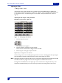
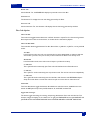
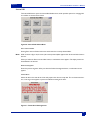
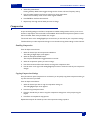
Getting to Know Your Deva Recorder
This section describes the physical features and location of items on the Deva recorder.
1
2
9
3
8
4
7
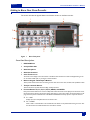
Figure 1
6
10
5
Deva Front panel
Front Panel Descriptions
1.
DVD-RAM Drive
2.
CompactFlash Slot
3.
Slate Microphone
4.
Slate Mic Activation
5.
Color Touch Screen
The touch screen display is the main interface of the Deva. Most selections are made and displayed using it. You
can use either a PDA stylus or your finger to make selections.
6.
Numeric Keypad and Backspace Buttons
These provide an alternative means of entering numeric data such as time code, metadata, and equalization values.
7.
Transport Control Buttons
These three buttons provide the Record, Play, and Stop functions.
8.
Function Buttons F1, F2, F3, F4, F5, F6, MENU, and ENTER
Many of the function buttons are used for multiple tasks. When the touch screen display shows the home screen,
the function buttons perform the function written above them. In other menu modes, the function buttons can be
programmed to perform additional tasks. The MENU and ENTER button always perform only those functions.
q
F1 —CUE
Displays the 'Cue' or Playback Menu on the touch screen.
q
F2 —C.TAKE
Marks a take as a 'Circled Take' in the metadata file. This button can be pushed either during record or after
the take has been recorded but before the next take has started.
4
Deva 5.8 and Deva 16 Owner’s Manual
q
Chapter 1
F3 —FALSE START
Marks a take as a 'False Start' in the metadata file. When this is done, the segment number does not increment when placed into the record mode the next time. This button can be pushed either during or right after
the false start record.
q
F4 —TIME CODE
Displays the Time Code menu on the touch screen.
q
F5 —S.T.N.s
Displays the SCENE TAKE NOTE menu.
q
F6 —HEADPHONE
Displays the HEADPHONE matrix menu, or the headphone volume if fade 8 is assigned.
q
MENU
Advances the screen to the next menu. This is the same as touching the status button in any menu.
q
9.
ENTER
Confirms data entry.
Faders 1 through 8
There are sight hardware faders. They can be assigned to any channel or combination of channels in
your Deva. Software faders are available for channels not assigned to the hardware faders.
10. Headphone volume/ Fader 8
When Fader 8 is not assigned to a channel, the fader becomes the headphone volume. When assigned
to a channel, the headphone volume is adjustable using the headphone button and the touch screen
volume slider.
5
Chapter 1
Deva 5.8 and Deva 16 Owner’s Manual
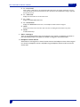
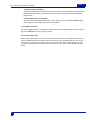
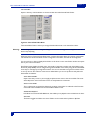
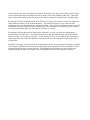
Left Panel Descriptions
11
1
10
9
Figure 2
8
7
6
5 4
3
2
Deva Left panel
1.
Hard Drive Compartment
2.
USB Port
This port is designed to connect Zaxcom approved keyboards.
3.
Time Code Connector
This is the standard 5 pin Lemo connector used for Time Code I/O (Lemo part number: EGG.OB.305.CLL)
4.
Serial / RS422 connector
This 9-pin connector is used for controlling the Deva using an external device such as the Zaxcom Deva MIX-12
mixer.
5.
Word Clock Output
This BNC connector provides a word clock timing output generated internally from the Deva.
6.
IEEE 1394 (FireWire) connector
This is a FireWire 400 port which can be used with FireWire hard drives, CD, and DVD-RAM drives. If the
external FireWire device requires power, it can be turned on from the My Deva menu. (see My Deva Menu on
page 71).
7.
AES Digital Input Connector
Connect the supplied AES Digital input cable to this 15-pin mini sub-D connector. The cable provides four pairs of
AES inputs.
8.
AES Digital Output Connector
Connect the supplied AES Digital output cable to this is a 15-pin mini Sub-D connector. The cable provides four
pairs of AES digital output.
9.
Power Switch and LED
When the Deva is powered on the green LED illuminates.
6
Chapter 1
Deva 5.8 and Deva 16 Owner’s Manual
10. Battery Compartment
The black knob rotates to lock the battery compartment door. Use NP-1 type batteries with the Deva. You can
safely use Li-ion and NiMH NP-1 batteries in the Deva as long as their maximum voltage does not exceed
18 VDC.
11. Power Input Connector
Standard 4-pin XLR connector for 9.5V-18VDC 1 Amp input
Note: At this time the REF 1 connector does not function.
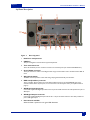
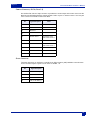
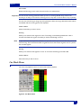
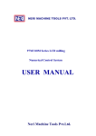
Right Side Panel Description
4
5
3
2
Deva 5.8
1
6
5
3
Figure 3
1.
2
Deva 16
1
Deva Right panel
Mic / Line Inputs 1 through 8
Each balanced input is internally padded to handle either mic or line level signals. The signal level is selected using
the Input Control screen. (Line Input Impedance is 4 KΩ).
7
Chapter 1
Deva 5.8 and Deva 16 Owner’s Manual
2.
Headphone Output
1/4-in. Stereo Jack, optimal 100 Ω impedance.
Note: Lower headphone impedances result in louder headphone output levels.
3.
Analog Outputs 1- 6
25-pin connector outputs 6 channels of line level audio. You can select the channels assigned to these
outputs from the Deva menu.
4.
Camera Connector (Deva 5.8 only)
This is a standard 10-pin Hirose ENG type camera connector. It outputs Channels 5 and 6 to the camera and
returns the monitor feed from the camera.
Note: The two return monitor feeds are summed to mono.
5.
Battery Ejection Pin
This pin ejects the NP-1 battery from the battery compartment.
6.
Analog 9-12 Input Connector (Deva 16 only)
This 10-pin Hirose ENG connector is for the included cable, allowing you to use analog channels 9
through 12.
8
Deva 5.8 and Deva 16 Owner’s Manual
Chapter 2
Chapter 2
Setting Up the Power and Audio Connections
This section describes how to connect external microphones, line devices and the proper settings on the
Deva required to make these connections work.
Deva 5.8 has factory default presets so you can power up the machine and start recording. When you
power on the Deva, it takes 3-5 seconds to start-up. The default setting has the home screen appear once
the Deva has finished its startup sequence, however you can change this using the User Interface Settings.
Power
An external A/C power supply comes with the unit, if you are going to use the Deva in a situation where
there is no power, an internal or external battery can be used.
Internal Batteries
The Deva uses a single NP-1 style battery. All types of NP-1 batteries can be used, including newer style
lithium ion batteries.
Important: The Deva does not charge the NP-1 battery when a battery is installed and external power is used.
External Batteries
The Deva can also use external batteries as long as they supply the proper voltage of 9.5-18 VDC. External
batteries are connected using a four-pin XLR and the power input connector on the left panel of the Deva.
Whenever the power input connector has an adequate power source connected, it is the source of power
for the Deva.
Hint:
If you need to run on battery power for an extended period of time, and need to record during this time,
connect an external battery to Deva when the internal battery is low. When an external power source is
used, the Deva automatically switches to this power source. This enables you to continue recording while
you switch out the internal battery.
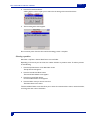
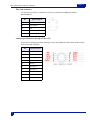
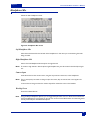
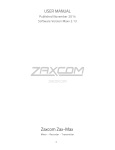
Battery Display
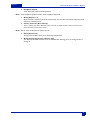
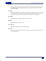
The home screen displays the source of power and voltage.
Home Screen
Figure 4
Home Screen
When the voltage of any internal or external power source drops below the custom defined threshold, the
battery indicator changes to red. When the voltage of the power source drops below 9.5 volts the Deva
powers itself off.
9
Chapter 2
Warning:
Deva 5.8 and Deva 16 Owner’s Manual
When the Deva shuts itself off due to power loss or insufficient power. The audio tracks are left in the “open” state.
When the unit is turned back on, it automatically scans these files and close them. However, this process can take
several minutes.
Battery Chemistry
When using newer chemistry batteries, such as lithium-ion, you must be aware of their unique power
curve. Up until the point where these batteries are exhausted, they show a full-charge. When using these
types of batteries, it is best to test how long it normally takes for the battery to discharge fully, and use this
time as your guide along with the battery meter.
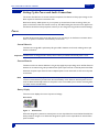
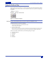
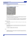
Setting the Battery Threshold
The Battery Menu is accessed by pressing the battery indicator on the Home Screen.
Home Screen > Battery Menu
Figure 5
Battery Menu
The graph shown in the Battery Menu displays the voltage and how long the battery has been used. The
curve is unique for each type of battery used (liON, NiMH). To change the threshold when the battery
indicator changes to red on the Home screen, do the following:
1.
Press the Low Battery Voltage button.
2.
Using the keypad, enter the threshold voltage
3.
Either Press the Low Battery Voltage button again, or Press the Enter key on the keypad.
4.
Press Stop to return to Home screen.
Current Draw
The Deva draws approximately 900 mA while recording. This current increases if powering an external
FireWire drive or when mirroring to the optional internal DVD-RAM drive.
Audio Input
The Deva supports both analog and digital audio inputs. The right side of the Deva has eight analog XLR
inputs. The AES digital input connector is on the left side of the Deva and requires the breakout cable
supplied by Zaxcom.
10
Deva 5.8 and Deva 16 Owner’s Manual
Chapter 2
Microphone/Analog Line Input
The eight analog input connections can be used with either microphones or with a line level analog input.
Caution:
Prior to connecting any analog input to the Deva, you should ensure the Microphone/Analog Line Input
Connectors are setup correctly in the Analog Input Control menu.
When connecting microphones, you should always connect them with the power off on the Deva.
Setting Up the Analog Inputs
The Input Control menu contains the settings for
o
toggling the connectors input
options: line and microphone.
o
toggling the connectors power
options: 48 VDC and None
o
Toggling the High Pass Filter
options: On and off
o
Adjust Delay of any available channel
o
Adjust trim of any available channel.
o
Assigning output routing
o
Equalization (EQ)
o
Enabling the input limiter
o
Enabling and adjusting the compression settings
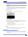
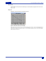
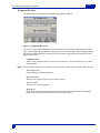
The Input Control menu is accessed from the Main Menu.
Main Menu > Input Control
Figure 6
Analog Input Control Screens
Pressing the Stop button in the upper right corner or menu key on the keypad brings you back to the main
menu.
Pressing any of the channel buttons, displays the Input Channel menu for that channel. All functions for a
single input channel can be adjusted from within the Input Channel menu.
11
Chapter 2
Deva 5.8 and Deva 16 Owner’s Manual
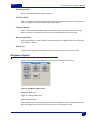
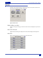
Main Menu > Input Control > Input Channel
Figure 7
Single Channel Analog Input Screen
Switching Between Microphone and Line Input
The Mic/Line button on the Input Control menu allows you to toggle the analog inputs between the
microphone and line input.
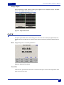
Main Menu > Input Control
Figure 8
Mic/Line button
To toggle between the settings, perform the following:
1.
Press the Mic/Line button on the screen.
The LED on the Mic/Line button flashes green indicating it is active.
2.
Press the channel button on the screen for channel you want change.
The channel button displays the current mic/line setting
You can continue toggling the Mic/Line option to each channel as required without pressing the Mic/Line
Level button each time, simply press the channel you want power applied to while the LED flashes on the
Mic/Line Level button.
If you press the Mic/Line button without pressing the Mic/Line button, you open the Input Channel screen.
12
Deva 5.8 and Deva 16 Owner’s Manual
Chapter 2
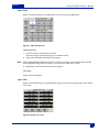
Enabling the High Pass Filter (HPFencounteredns encounted with microphones.
o Range: 30 Hz - 240 Hz
Main Menu > Input Control
Figure 9
High Pass Filter Button (Input Control Menu)
Setting the High Pass Filter value
To set the High Pass Filter value, you must use the HPF button in the Input Channel menu.
Main Menu > Input Control > Input Channel
Figure 10
High Pass Filter Button (Input Channel Menu)
Perform the following to enable the High Pass Filter
1.
Press the individual channel button.
2.
Press the High Pass Filter button.
a dialog appears.
3.
Enter the frequency using the numeric keys.
The valid frequency range is 30 Hz to 240 Hz. Any value outside this range is place closest to most
valid number with this range.
4.
Press the enter key on the front of the Deva to finish entering the HPF cutoff.
Note: The HPF value last entered is used as the default value for the next HPF frequency.
Setting the High Pass Filter Frequency on Multiple Channels
Once a HPF value has been entered, you can use the High Pass Filter button on the Input Control menu
(shown in Figure 9) to quickly enable the HPF on multiple channels. Use the following steps to enable the
HPF on multiple channels.
13
1.
Press the High Pass Filter button on the Input Control menu.
The LED flashes green indicating it is active.
2.
Press the channel you want the High Pass Filter applied to.
HPF indicator on the button changes to last HPF frequency used.
Chapter 2
Deva 5.8 and Deva 16 Owner’s Manual
3.
Hint:
Press the High Pass Filter button again when all channels are enabled.
To quickly disable the High Pass Filter, press the High Pass Filter button on the Input Control menu, and
then press the channels you want to disable.
Enabling Phantom Power (48 VDC)
Some microphones require power to operate. The Deva supplies the full power and current allowed by the
phantom power specification (48 VDC up to 1.0 A). The Deva does not supply 12T power which is
required by some older microphones. If you use microphones requiring 12T power, check with your local
audio dealer for phantom to 12T power converters.
Main Menu > Input Control > Input Channel
Figure 11
Phantom power button on the Input Channel menu
To enable phantom power, perform the following:
1.
Press the channel on the Input Control menu you want phantom power applied to.
The Input Channel menu appears.
2.
Press the 48 V Off button.
The 48V button changes to red and changes to 48V On indicating it is active.
3.
Press the channel you want phantom power applied to.
48 V on the button turns red and changes to 48 V On to indicate 48 VDC is applied to that channel.
Phantom off
Phantom on
Important: To protect equipment from damage, the Deva does not allow you to apply power to any channel set as a
Line input.
14
Deva 5.8 and Deva 16 Owner’s Manual
Chapter 2
Adjusting the Trim
o Range: -20 dB to +30 dB
There are two ways to adjust the input trim on channels. If you have multiple inputs, the Analog Trim
Screen allows you adjust all of them from a single screen. However, if you are making individual adjustments
to channels the trim can be adjusted using the on-screen fader in the Input Channel menu (shown in
Figure 7).
Adjusting the Trim using the Analog Trim Menu
Main Menu > Input Control > Adjust Trim
Figure 12
1.
Analog Input Trim Menu
Press the Adjust Trim button.
The Analog Trim menu appears.
2.
Press the meter for the channel you want to adjust.
When a channel is activated, Trim changes from black to Blue.
3.
Either Less gain or More gain to adjust a channel.
Repeat steps 1 through 3 for each channel.
All Trim settings can be reset to 0 dB by pressing the Clear Trim button. A dialog appears after pressing the
Clear Trim button requesting confirmation that you want to clear all the trim settings.
Note: If all channels are going to be set at the same level, you can save time by changing them at the same time. Press the
Select All button, then any change made to the levels are applied to all channels at the same time.
Pressing either the STOP button in the upper right corner of the screen or using the Menu key on the
keypad exits the Adjust Analog Trim screen and brings you back to the Analog Input Control screen.
15
Chapter 2
Deva 5.8 and Deva 16 Owner’s Manual
Adjusting Individual Trim Levels Using the Analog Input Channel menu
Main Menu > Input Control > Input Channel
Figure 13
Individual Input Trim Fader
The input trim fader works a real fader on a mixing board. You use the Deva touch screen to move the
trim fader up and down.
Perform the following to change the trim on an individual channel:
1.
Press the individual channel button on the Input Control menu.
2.
Slide the fader to the desired position.
Adjusting The Delay
o Range: 0 to 40 ms
The delay in the Deva provides a way to monitor various input sources that may come into the Deva at
slightly different times. For example, most wireless microphones typically require 2 to 3 ms of delay to
avoid phasing associated with using wireless and wired microphones on a mix track. The delay does not
affect the input signals actual time code, it simply allows the signal to come into alignment with other
sources that are mixed with it. Both analog and digital inputs can have delay added to them.
There are two ways to adjust the delay on channels. If you have multiple inputs, the Analog Input Delay
menu allows you adjust all channels from a single screen. However, if you are making individual adjustments
to channels the delay can be adjusted using the delay button in the Input Channel menu (shown in Figure 7).
16
Deva 5.8 and Deva 16 Owner’s Manual
Chapter 2
Adjusting the Delay Using the Input Delay Menu
Main Menu > Input Control > Analog Input Delay
Figure 14
Analog Input Delay
To adjust the delay of multiple channels using the Analog Input Delay menu, perform the following:
1.
Press the Adjust Delay button on the Input Control menu.
The Adjust Delay Screen Appears. You can adjust delays on both Analog and Digital inputs.
2.
Press the channel you want to add delay into.
The button changes to white.
3.
Press More delay to add delay.
If Delay has been added to a channel, the Less Delay button is active and can be used to reduce the
amount of delay.
A maximum of 40 ms of delay can be added to each channel.
Repeat Steps 1 through 3 for each channel as required.
As an alternative to pressing the More Delay or Less Delay buttons, you can press the Enter Delay and
manually enter the delay using the keypad.
Pressing either the STOP button in the upper right corner of the screen or using the Menu key on the
keypad exits the Adjust Delay menu and brings you back to the Analog Input Control menu.
17
Chapter 2
Deva 5.8 and Deva 16 Owner’s Manual
Adjusting Delay Using the Analog Input Menu
Main Menu > Input Control > Analog Input Channel
Figure 15
Delay Adjustment on Analog Input Menu
Perform the following to adjust delay on individual channels:
1.
Press Delay on the Analog Input Channel menu
A dialog appears requesting the amount of delay.
2.
Enter the amount of delay using the keypad on the Deva
3.
Press Enter to complete entering the delay amount.
Pressing either the STOP button in the upper right corner of the screen or using the Menu key on the
keypad exits the Analog Input Channel menu and brings you back to the Analog Input Control menu.
Digital Inputs
The Deva comes with an AES Digital Input cable. This cable gets connected on the left side of the Deva, see
Left Panel Descriptions on page 6 for the location of this connector.
The AES cable fans out to four separate XLR style inputs. Each input is a stereo pair (Input 1,2; Input 3,4;
Input 5,6; Input 7,8). You can use any combination of these inputs with your Deva. The input number is
written on each cable. You can assign these inputs to any channel or combinations of channels.
No special settings other than delay is available for digital inputs. See “Adjusting The Delay” on page 16 for
instructions on adjusting the delay.
Analog Outputs
The Analog outputs on the Deva go through a DB-25 connector located on the right side of the Deva.
There are six outputs available through this connector. A break-out cable can be purchased from Zaxcom
as an option, or through many retailers. A wiring diagram is also provided in this manual if you want to
manufacture your own break-out cable.
The six outputs can be assigned from any combination of channels.
18
Deva 5.8 and Deva 16 Owner’s Manual
Chapter 2
Digital Outputs
The Deva comes with an AES digital output cable. This cable connects to the left side of the Deva using
DB-15 connector. There are eight digital outputs available using this connector.
The AES cable fans out to four separate XLR style outputs. Each output is a stereo pair (Output 1,2;
Output 3, 4; Output 5,6; Output 7,8). You can use any combination of these outputs with your Deva. The
output channel number is written on each cable. You can assign these outputs to any channel or
combinations of channels.
Camera Connector
The Camera Output connector is located on the right side of the Deva. It is a 10-pin Hirose connector.
Only output channels 5 and 6 can be used through this connector. These channels are summed into a mono
feed.
Hint:
Because the audio output of this connector is summed, you cannot use this output to feed audio and timecode to a camera using separate channels. To do this, use the analog output for the timecode channel.
Break out cables are available from retailers, and pinout diagrams for the connector are available in this
manual if you want to make your own cable.
A return input from the camera headphone output is available using the camera connector. When used, the
audio from the camera can be monitored using the Deva.
Assigning Inputs and Outputs to Tracks
The flexibility of the Deva is highlighted in the way it handles the routing. Routing on the Deva allows you
to assign any combination of inputs to any combination of channels and outputs. This section describes
how to assign both inputs and outputs.
Assigning Inputs to the Recording Tracks
Input Options: Analog Input, Digital Input, Pre-fader, Post-fader, Phase Inverted
A single digital or analog input can be assigned to any number of recording tracks, including sharing the
same recording channel, using the Disk Channel Mix matrix.
19
Chapter 2
Deva 5.8 and Deva 16 Owner’s Manual
Main Menu > Disk Channel Mix
Figure 16
Disk Channel Mix Matrix
Each track can have an input be pre- or post-fader, or have the input’s phase inverted. This can be done for
both analog or digital signals. Since there are many options, some of the steps listed in the following steps
can be skipped.
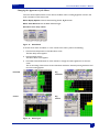
To assign an input to a track, perform the following:
1.
Press Analog In Toggle or Digital In Toggle to change the input source you are assigning.
The button changes indicating which input is currently active.
2.
Press Post-Fader or Pre-Fader to change what type of signal you want recorded.
The button changes indicating what type of signal you want assigned. Pre-fader signals are not affected
by any changes made using faders, however all EQ, Trim, and delay settings made to a track are used.
3.
Press the square on the matrix where you want the signal assigned.
The top row lists all the inputs and the column on the right lists all the disk channels.
In Figure 16, channel 1 has a post-fader digital signal from input 1, a post-fader signal from input 2, and
a post-fader signal from input 3 assigned to it. Channel 2 has the pre-fader signal from input 1 assigned
to it, channel 3 has the pre-fader signal from input 2 assigned to it, and channel 4 has a pre-fader signal
from input 3 assigned to it.
4.
Press Phase Invert to invert the phase of a signal.
The LED changes to green when the Phase Invert in active.
20
Chapter 2
Deva 5.8 and Deva 16 Owner’s Manual
5.
Press input you want change the signal phase inverted on.
You can invert the signal on both digital and analog inputs.
Figure 17
Sample Routing combinations
Setting the Number of Tracks Recorded
Once the routing is assigned, you have to enable the tracks to record. This is done in the Record Tracks
menu.
Main Menu > Deva Setup > Record Channels
Figure 18
Record Tracks menu
Any track that has an input assigned to it, displays blue in the Record Track menu. You can record any
combination of tracks, however you must have at least one track enabled for recording. Four buttons are
available which enable you to quickly setup the number of tracks recorded.
Perform the following to enable tracks for recording:
1.
Press the button below the track.
An ’x’ is placed in the button indicating it is enabled for recording.
Track Enabled
Track Disabled
Once a track is enabled for recording, pressing the button again disables recording of that track.
Hint:
21
Pressing the backspace button on the Deva keypad, then pressing the appropriate meter on the Home
Screen toggles the recording of that track.
Chapter 2
Deva 5.8 and Deva 16 Owner’s Manual
Setting Sampling Rate For Recorded Tracks
Sampling Rate Options: 44.1 kHz, 47.952 kHz, 48 kHz, 48.048 kHz, 88.2 kHz, 96 kHz, 96.096 kHz,
192 kHz
Main Menu > Deva Setup > Internal Sample Rate
Figure 19
Internal Sample Rate Menu
Setting the sampling rate on the Deva consists of simply pressing the button for the sampling rate required.
Note: After changing sampling rates timecode may need to be re-jammed.
Setting Up 192 kHz Recording
Recording at 192 kHz requires large amounts of the Deva’s processing cycles. Because of this, you must
enable it when powering on the Deva. Zaxcom recommends that you reduce your recording channels to
two, turn off any EQ, and unneeded routing when recording at 192 kHz.
To enable 192 kHz, perform the following:
1.
Power down the Deva
2.
Press and hold the 9 on the Deva’s number keypad
3.
Power on the Deva.
The startup screen will indicate that 192 kHz recording is now enabled.
4.
Go to the Internal Sample Rate menu and you can now enable 192 kHz.
Once enabled, you can change the number of tracks recorded, up to eight tracks.
Not Enabled
Figure 20
Enabled
192 kHz recording button
22
Deva 5.8 and Deva 16 Owner’s Manual
Chapter 2
Assigning Inputs to Output Channnels
Assigning the audio inputs to output channels is identical to assigning audio inputs to recording channels.
They use the same style matrix and have all the same settings.
Main Menu > Output Mix
Figure 21
Output Channel Matrix
In Figure 21, Input 1 is a digital signal assigned to two different outputs. Output channel 1 receives a prefader version of the signal, while channel 6 receives a post-fader version of the same signal along with both
a tone signal and post-fader analog signal from input 3. Channel 3 receives a pre-fader version of input 2,
while output 5 receives a post-fader version of input 2 along with a tone signal.
Like the recording matrix, any combination of signals can be assigned to a vast number of output
possibilities.
Overview of Input Signals
The Input Meter Men provides a quick overview of all input signals. Because of the flexibility of the routing,
you may run into situations where you need to try to determine if a signal is actually coming into the Deva.
Main Menu > Deva Setup > Meters > Display Inputs
Figure 22
23
Input Meter Menu
Chapter 2
Deva 5.8 and Deva 16 Owner’s Manual
Overview of Output Signals
The Output Meter Menu provides a quick overview of all output signals. This allows you to see where
routed signals are going.
Main Menu > Deva Setup > Meters > Display Outputs
Figure 23
Output Meter Menu
24
Deva 5.8 and Deva 16 Owner’s Manual
25
Chapter 2
Chapter 3
Deva 5.8 and Deva 16 Owner’s Manual
Chapter 3
Settings for Recording
Once the input cables are connected, there are many setup decisions to be made. In the previous section,
the basic settings for the input and output channels were explained and setup. This section describes
additional recording settings and where they are found in the menus.
Note: There is no one way to setup a Deva correctly, nor do any of the settings described here have to be done in any
certain order.
Storing the Data
The size of the hard drive determines how much data can be stored.
Formatting a Drive
A new drive must be formatted before it can be used. Drives shipped from Zaxcom are pre-formatted for
the Deva, however it is a good idea to format all drives again before using them. When you format a drive,
it does a high level format of the drive. If a copy of the Deva firmware is installed on the hard drive, it is not
erased.
Main Menu > My Deva > Internal HD Drive > Internal Disk Utilities > Format Drive
Figure 24
Internal Disk Utilities Menu (Format Drive Button highlighted)
To format, or initialize, the internal hard drive, perform the following:
1.
Press Format Drive button
The format menu warning appears.
26
Deva 5.8 and Deva 16 Owner’s Manual
2.
Press the Format Drive button.
A dialog appears, which request you to confirm the formatting of the internal hard drive.
3.
The formatting status menu appears.
Chapter 3
Do not remove power from the deva until the formatting process is complete.
Selecting a partition
Main Menu > My Deva > Internal Hard Drive > Current Folder
Depending on the size of your hard drive, the number of folders or partitions varies. To select a partition
do the following:
1.
Press the My Deva button on the Main Menu screen.
The My Deva Screen appears.
2.
Press the Internal Hard Drive button.
The Internal Disk Utilities screen appears.
3.
Press the Current Folder button.
the Internal Disk Folders screen appears.
4.
Press the folder name you want to record on.
The folder’s button turns white.
The Internal Disk Folders screen also allows you to erase the contents within a section, rename the folder,
and change the view order of the folders.
27
Chapter 3
Deva 5.8 and Deva 16 Owner’s Manual
Setting the Pre-Record Time
From the point the Deva is powered on, it is always processing data. Any sound coming in from any input is
always being processed. When Pre-Record Time is enabled the buffered sound is placed at the beginning of
the segment.
o Range: 0 - 10 Seconds
Main Menu > Deva Setup > Pre-Record Time
Figure 25
Pre-Record Time Button
Important: In order to use the Pre-Record Time, you must use a sample rate of 48.08 kHz or lower.
To enable Pre-Record Time, perform the following:
1.
Press the Deva Setup button on the Main Menu screen.
The Deva Setup Screen appears.
2.
Press the Pre-Record Time.
Each time you press the button, the time is increased one second from Off (0) to the maximum of 10
seconds. The amount of prerecord time is shown in blue just above the Pre-Record Time button.
The Pre-record buffer is discarded after any of the following settings are changed:
o
Sample Rate Reference
o
Sample Rate
o
Timecode
o
Userbits
o
Frame Rate
28
Chapter 3
Deva 5.8 and Deva 16 Owner’s Manual
Setting the Tone Levels and Outputs
The Deva provides a calibrated tone level, which can be placed on any output channel or recorded track.
This tone level is used to calibrate cameras to the audio sent from the Deva, and post-production facilities
to ensure all levels are correct.
o
Level Options: -20 dB, -18 dB, -16 dB, -14 dB, -16 dB
Main Menu > Deva Setup > Tone Level
Figure 26
Tone level Button
Perform the following to set the tone level:
1.
Press the Deva Setup button on the Main Menu screen.
The Deva Setup Screen appears.
2.
Press the Tone Level button.
Each time you press the button, the tone is increased 2 dB, from it’s previous setting. When -16 dB is
reached, the tone level automatically cycles back to -20 dB.
The tone level is shown in blue just above the Tone Level button.
Setting Tone output
Once the tone level is selected, you have to set where the tone is placed. Unless you set a record track or
output channel, tone is being generated, but not used.
Main Menu > Disk Mix
Figure 27
Main Menu > Output Mix
Tone Selection on Disk Channel Mix menu and Output Channel Mix menu
Setting the tone on the recording track and output channel are identical. Perform the following to set the
track or channel:
29
1.
Open the Disk Channel Mix menu or Output Channel Mix
2.
Press the record track or output channel you want tone placed on.
an ’x’ appears on tracks and channels selected.
Chapter 3
Deva 5.8 and Deva 16 Owner’s Manual
Enabling Tone
Tone is enabled from the main menu by pressing the tone button. It is placed on those tracks and channels
previously selected.
Main Menu
Tone On
Tone Off
Figure 28
Tone Button disabled (off) and enabled (on)
Home Screen Meters
You can have up to 16 meters displayed on the home screen. Each of these meters can be labeled and the
label information stored in the metadata of the audio file.
Setting the Number of Meters
Range: 4 to 16 (Deva 16), 4 - 10 (Deva 5.8)
You can have up to 16 meters shown on your home screen. Any track meter shown on the home screen
that is not being recorded on, displays with a line through it.
Main Menu > Deva Setup > Meters > Number of Home Screen Meters
Figure 29
Home Screen Meter Button
Important: Make sure to have at least the same number of channels displayed on the home screen as you are
recording. It is possible, to record and mix tracks which will have no meter shown on the home screen.
To set the set the number of meters, perform the following:
1.
Press the Deva Setup button on the Main Menu screen.
The Deva Setup Screen appears.
2.
Press the Meters button
The Meters Menu screen appears.
3.
Press Number of Home Screen Meters to change the number of meters that appear on the home
screen.
The number of channels that appear on the home screen changes and is shown in blue above the
button. Continue pressing the button until the correct number of tracks appears.
30
Deva 5.8 and Deva 16 Owner’s Manual
Chapter 3
Setting the Meter Labels
Range: Labels can be a maximum of 16 characters
Meter labels on the Home Screen do more than just provide an easy reference of what is on each track
when meters are displayed horizontally. This information is place into the metadata of the broadcast wave
file. This information can be used in automated sound reports, used by post-production and audio software
to label tracks.
Note: When the maximum character limit has been reached, any additional character is placed in the 16th character
position.
Main Menu > Deva Setup > Meters > Meter Labels
Figure 30
Meter Labels Button
Main Menu > Deva Setup > Meters > Meter Labels > Meter Labels Menu
Figure 31
Meter Labels Menu
To change the meter labels, perform the following:
Hint:
31
1.
Press the Deva Setup button on the Main Menu screen.
The Deva Setup Screen appears.
2.
Press the Meters button
The Meters Menu screen appears.
3.
Press the Meter Labels button.
The Meter Labels Menu appears.
4.
Press the Meter number button that you want to label.
A keyboard layout appears.
5.
Press the letters to enter the label.
If you press the backspace key (Bsp) characters are removed from the label.
Using a PDA stylus, external keyboard, or the Deva MIX-12 with its built-in keyboard increases accuracy
and speed entering labels.
Chapter 3
Deva 5.8 and Deva 16 Owner’s Manual
Changing the Appearance of the Meters
There are several adjustments that can be made to the Deva meters, including brightness of meters, and
meter orientation on the home screen.
Meter Display Options: Vertical, Horizontal, Big Vertical, Big Horizontal
Meter Color Schemes: Normal, Black & White, Bright
Main Menu > Deva Setup > Meters
Figure 32
Meter Menu
To set the set the meter orientation, or color scheme of the meters, perform the following:
1.
Press the Deva Setup button on the Main Menu screen.
The Deva Setup Screen appears.
2.
Press the Meters button
The Meters Menu screen appears.
3.
Press Meter Vertical/Horizontal or Color Schemes to change the meters appearance on the home
screen.
The current setting of the meter is shown in blue above the button. Continue pressing the button until
the correct setting appears.
Horizontal
Big
Horizontal
Vertical
Big
Vertical
Figure 33
Meter Types
32
Deva 5.8 and Deva 16 Owner’s Manual
Chapter 3
Note: Only meters displayed in the horizontal orientation display labels on the home screen due to space restrictions.
Changing the Meter Orientation from the Home Screen
A shortcut is available on the home screen allowing you to toggle the meter orientations quickly. Next to
the status mode is the view (’V’) button. Pressing the view button toggles through the meter orientations.
Figure 34
View Button Highlighted
Meter Color Schemes
The Bright and Black & White settings were designed for using the Deva in full sunlight. Both allow you to
see and use the Deva screen when viewing conditions are less than ideal.
Headphone Monitoring
One of the strengths of the Deva is the flexibility in routing, which is evident in the input, output, and
recording options. This flexibility is extended to the headphone monitoring area as well. Many common
headphone monitoring options come preset from Zaxcom. You can add up to 12 custom presets in
addition to the factory presets. You can also simply build a headphone monitoring configuration on-the-fly
without saving it, as well as temporarily monitor a single channel. The headphone audio you are listening to
what is being placed onto the hard drive. Check-Sum Error Correction ensures that what is being sent to
the internal hard drive is being recorded there.
Main Menu > Headphone Mix
Headphone Mix Menu
There are two shortcuts to getting to the Headphone Mix menu:
o Press the F6 key on the Deva,
o Press headphone display area on the home screen.
Both of these bring you immediately to the Headphone Mix menu, as long as fader number 8 is not assigned
to a track.
33
Chapter 3
Deva 5.8 and Deva 16 Owner’s Manual
Fader 8
Fader 8 serves two purposes on the Deva 5.8 and Deva 16. When no track is assigned to fader 8, it
functions as the headphone output volume control. However, when a track is assigned to fader 8, it
functions as a normal fader. To adjust the headphone volume when fader 8 is assigned, a Headphone
Volume menu is used.
F6 > Headphone Volume
Figure 35
Headphone Volume Menu (Fader 8 assigned)
To adjust the headphone volume with fader 8 assigned perform the following:
1.
Press F6 on front of the Deva.
2.
Use the slider to adjust the volume.
Loading a Factory Preset
To load a Factory Preset, perform the following:
1.
Press F6, the Headphone area on the home screen, or Headphone Mix on the Main Menu.
The Headphone Mix menu is displayed.
2.
Press Get Factory Presets
The Factory Preset Screen Appears.
3.
Press the preset button you want to use.
34
Chapter 3
Deva 5.8 and Deva 16 Owner’s Manual
Main Menu > Headphone Mix > Get Factory Presets
Figure 36
Get Factory Preset Menu
Building Your Own Headphone Mix (Working Preset)
On the Headphone Mix menu, all tracks marked for recording are displayed in blue. All other tracks have a
red slash through them. This is shown in the following figure:
To build your own headphone mix, from the Headphone Mix menu perform the following:
1.
Press the button in the left or right headphone output to assign to that headphone output channel.
An ’x’ is placed in the button.
Invert Phase
When building M+S monitoring phase of one of the channels needs to be inverted. Use the Phase Invert
button to invert the playback phase of any channel. The Deva displays
indicating the channel is
inverted.
Important: Invert Phase only inverts the playback phase, it does not affect the recorded audio in any way.
Camera Input
The Camera Input button allows you to perform confidence audio monitoring from the camera using the
camera connector on the right side of the Deva. When you enable the Camera Input, you will want to
temporarily disable any other headphone channels being monitored, otherwise you will hear the delayed
audio from the camera on top of those channels.
Note: The Camera Input on the Deva internally sums the camera mix to mono. This summing occurs only on the return
audio, not audio sent to the camera.
35
Chapter 3
Deva 5.8 and Deva 16 Owner’s Manual
Building Your Own Presets
In a lot of cases once you have setup monitoring options, you don’t need to change them that often. But
once changed, the Deva allows you to with the push of a button, restore those settings. When stored,
these become known as User Presets.
Store User Presets
The following section provides instructions on storing monitoring presets. You can have up to 20 presets.
To store a preset, perform the following:
1.
Setup the monitoring matrix.
2.
Press the Store User Presets.
The Store User Preset Menu appears.
3.
Press any unassigned preset button.
The on-screen keyboard appears.
4.
Enter the name for your headphone preset.
You use up to eight (8) characters for your preset name. Press the Enter key when finished.
Note: The preset name does not immediately appear on the button. However, the next time you go into the Get User
Presets or Store User Presets menu, the name will appear on the button.
5.
Press the menu button to return to the Headphone Mix menu.
The name of the preset appears above the headphone assignment buttons.
36
Deva 5.8 and Deva 16 Owner’s Manual
Chapter 3
The preset name and User Preset number also appears on the home screen in the headphone monitoring
area.
Changing Preset; Get User Presets
The Get User Presets allows you to recall any of the presets you previously stored.
To change to a different preset, perform the following:
1.
Press the Get User Preset button on the Headphone Mix menu.
2.
Press the button with the preset you want to use.
3.
Press the Menu button to return to the Headphone Mix menu.
Time Code
The Deva provides several time code options, which are all available from the Time Code menu.
To get to the Time Code screen, either press the Time Code button (F4), or press the time code in the
home screen.
Main Menu > Time Code
Figure 37
Time Code Menu
Static Time Code Settings
Reader T.C.
The Reader T.C. displays Time code from any External source coming into the Deva. If no external source
is present, you may temporarily see three question marks (???). These indicate that no external time code
source is being sensed by the Deva. When a source is connected, the Reader T.C. also displays the
estimated frame rate.
37
Chapter 3
Deva 5.8 and Deva 16 Owner’s Manual
Reader U.B.
Like the Reader T.C., the READER U.B. displays any external source’s User Bits.
Generator T.C.
The Generator T.C. displays the time code being generated by the Deva.
Generator U.B.
Like the Generator T.C., the Generator U.B. displays the user bits being generated by the Deva.
Time Code Options
Time Code Out
Time Code Out toggles between Generator and Disk. Generator outputs TC from the internal generator.
Disk outputs time code from the hard drive, or the disk which is selected for playback.
Time Code Run Mode
Time Code Run Mode toggles between Free Run, Record Run, C. JAM ALL, C. JAM T.C., and C. JAM U.B.
modes.
Free Run
In the Free Run mode, time code runs continuously from either 00:00:00:00: or whatever valid time
code number you enter, since you can also jam time code from the Deva’s ’Time of Day’ clock.
Record Run
In the Record Run mode, time code starts and stops as you Record and Stop.
C. JAM ALL
The C. JAM All mode continuously Jams Time code and User Bits from an External Source.
C. JAM T.C.
The C. JAM T.C. mode continuously jams only the time code. The user bits can be set independently.
C. JAM. U.B.
The C. JAM U.B. mode continuously jams the User Bits, while the time code FREE RUNS independently. This mode allows a second time code to be input as user bits from an external source.
Frame Rate
The Frame Rate button toggles the between all available time code frame rates. Available frame rates
include: 30 NDF (Non Drop Frame), 30 DF, 23.98, 24, 25, 29.97 NDF, and 29.97 DF.
Toggle Time Code Type
This button toggles the settings for entering and jamming data between Time code and User bits. This
selection changes the display on the 2 buttons to its right. JAM TIMECODE becomes JAM USER BITS and
JAM TIME OF DAY and ENTER TIMECODE becomes ENTER USER BITS and ENTER TIME OF DAY.
38
Deva 5.8 and Deva 16 Owner’s Manual
Chapter 3
JAM TIMECODE (USER BITS)
This button manually jams an external Time code or User bits into the internal generator. When set to
JAM TIME OF DAY it will jam the time code clock to the time of day entered in the Deva SETUP /
CLOCK menu.
ENTER TIMECODE (or USER BITS).
This button opens a window that allows you to input Time Code or User bit data. ENTER TIME OF
DAY brings you to the CLOCK setup menu in Deva SETUP.
INC USER BITS ON/OFF.
This button toggles between incrementing user bits On and Off. When ON, the Deva increments the last
digit in the USER BITS each time you go into record.
DUAL RATE TIME CODE
A feature of the Deva allows it to sync to one time code frame rate and record another. For instance, you
can input 23.98 time code from an HD camera and record 29.97 time code derived from it. The 2 frame
rates will be in perfect sync matching up at frame one of each second. Deva will hold perfect time code
sync even when cycling power. Many other time code clocks can gain or lose a frame each time power is
cycled.
39
Chapter 3
Deva 5.8 and Deva 16 Owner’s Manual
40
Chapter 4
Deva 5.8 and Deva 16 Owner’s Manual
Chapter 4
Pinouts
This section provides the pinouts for the connectors on the Deva. The mating cable connector part number is also provided for the less common connectors.
Analog Out - DB25
This is a standard DB-25 connector available at most electronic part stores.
Pin
Signal
Description
Pin
Signal
Description
Pin
Signal
Description
1
1+
10
5-
19
Ground
2
Ground
11
6+
20
Ground
3
4-
12
Ground
21
3-
4
5+
13
Ground
22
4+
5
Ground
14
2-
23
Ground
6
Ground
15
3+
24
Ground
7
1-
16
Ground
25
Ground
8
2+
17
6-
9
Ground
18
Ground
When building an analog cable, use the balanced XLR signals
Pin
41
Signal Description
1
Ground
3
Out Phase (-) / Cold
Pin
2
Signal Description
In Phase (+) / HOT
Chapter 4
Deva 5.8 and Deva 16 Owner’s Manual
Camera Connector, 10 Pin (Deva 5.8)
On the Deva 5.8, a Hirose 10-pin connector is provided as a camera output and a camera return into the
Deva 5.8 recorder. Balanced analog outputs channels 5 and 6 on pins 1-4. Camera returns 1 and 2 on pins
5 and 7, these are summed to mono in the Deva.
Pin
1
Signal Description
Notes
Channel 5
2
3
Channel 6
4
5
Camera return 1
6
N/C
7
Camera return 2
8
N/C
9
N/C
10
N/C
Summed to mono
with camera return 2
Summed to mono
with camera return 1
Power Connector
The Power Connector on the Deva is a standard 4 pin XLR connector (A4F) available at most electronic
stores. The Deva requires a power source of 9.5 to 18 VDC, 1 A.
Pin
Signal Description
1
-9.5 to -18 VDC (-)
2
N/C
3
N/C
4
+9.5 to +18 VDC (+)
42
Deva 5.8 and Deva 16 Owner’s Manual
Chapter 4
Time Code Connector
The Time Code connector on the Deva is a Lemo 5 pin connector. The LEMO part number is
EGG.OB.305.CLL.
Pin
Signal Description
1
Ground
2
Time Code In
3
N/C
4
N/C
5
Time Code Out
Analog Input Channels 9 through 12 (Deva 16)
On the Deva 16 analog input channels 9 through 12 use a 10-pin LEMO connector. These channels are line
level, and the cable is provided.
Pin
43
Signal Description
1
Input CH 9 +
2
Input CH 9 -
3
Input CH 10 +
4
Input CH 10 -
5
Ground
6
Input CH 11 +
7
Input CH 11 -
8
Input CH 12 +
9
Input CH 12-
10
Ground
Chapter 4
Deva 5.8 and Deva 16 Owner’s Manual
AES Digital Input
The Deva uses a DB-15 connector for the AES digital input connnector.
Pin
Signal Description
Pin
Signal Description
1
CH 3, CH 4 +
9
Ground
2
CH 1, CH 2 +
10
Ground
3
No Connect
11
CH 3, CH 4 -
4
CH 7, CH 8 +
12
CH 1, CH 2 -
5
CH 5, CH 6 +
13
No Connect
6
Ground
14
CH 7, CH 8 +
7
Ground
15
CH 5, CH 6 +
8
No Connect
AES Digital Output
The Deva uses a DB-15 connector for the AES digital outputs connnector.
Pin
Signal Description
Pin
Signal Description
1
CH 3, CH 4 +
9
Ground
2
CH 1, CH 2 +
10
Ground
3
No Connect
11
CH 3, CH 4 -
4
CH 7, CH 8 +
12
CH 1, CH 2 -
5
CH 5, CH 6 +
13
No Connect
6
Ground
14
CH 7, CH 8 +
7
Ground
15
CH 5, CH 6 +
8
No Connect
44
Deva 5.8 and Deva 16 Owner’s Manual
45
Chapter 4
Chapter 5
Deva 5.8 and Deva 16 Owner’s Manual
Chapter 5
Software Guide
The Deva is a very sophisticated recording device. The heart of the system is the software used to operate
the device. This section of the manual describes each screen on the Deva and the functions within each
screen.
Home Screen
This section describes the Home Screen. The Home screen is where you spend most of your time when
working on the Deva. It contains the timecode, headphone status, scene, take, note information, the status
of the device, battery levels, and signal levels.
Figure 5 Home Screen
The Status bar on the top of the screen displays Run, Stop and Play. Pushing this button from the Home
Screen takes you to the next menu. From any other menu, pressing the Status button takes you back one
menu or level within a menu or screen Pressing the Menu button on the front panel performs the same
function.
Note: Pushing the status button does not change the state of the Deva. It only brings you back one menu or level with a
menu or screen. It also displays the current status.
The HOME SCREEN is an active screen. Touching any of the following buttons with your finger or a stylus
takes you to its corresponding menu.
TIME CODE Button
(Figure 5 displays 00:00:00:00) takes you to the TIMECODE menu.
Headphone Button
The button with the Headphone icon takes you to the headphone menu. This area of the home screen
shows tracks are being monitored in the headphones.
Note: Individual tracks can be monitored in a solo mode by touching and holding the meter display for that track.
Mirror Status
The Mirror Status button takes you to the My Deva menu.
46
Deva 5.8 and Deva 16 Owner’s Manual
Chapter 5
CUR Total Folder
The CUR TOTAL FOLDER button opens the INTERNAL DISK FOLDERS menu providing access to the
disk directory and labeling functions.
Scene Take Notes
The bottom button opens the SCENE TAKE NOTES metadata Entry menu.
View (‘V’)
The ‘V’ button cycles between four different HOME SCREEN layouts these are shown in Figure 33 on
page 32.
Meters
Depending on the model Deva, either 8 or 10 tracks can be displayed. Tracks which are shown, but not
being recorded to have a line through them on the display. Individual tracks can be shown or hidden using
the Display # of Home screen Meters (Main Menu > Deva Setup > Internal Sample Rate). Ballistics are
Peak / Hold. The Peak Hold Bar remains for 5 seconds. The meter is calibrated in decibels.
Hint:
Pressing the backspace button on the Deva keypad while pressing the appropriate meter on the Home
Screen toggles the recording of that channel.
Solo Mode
You can Solo any input channel by touching the meter display for the desired track. Touch and hold the
desired track for 2 seconds. The display will enter ‘solo’ mode. Then, touching any other track instantly
solos that track. To exit ‘solo’ mode touch and hold any track for 2 seconds.
Battery Display
The battery Icon shows the current voltage of the power source (Int or Ext) that is powering Deva at that
moment. Deva will auto switch. If external power is applied and a battery is inserted, The Deva operates
on the external power until it drops below 9.5v. It then automatically switches to the internal battery.
Important: The Deva does not charge the internal battery.
PRE
PRE shows the selected amount of Pre-Record. In this case it is Off. Deva has a memory buffer. If the unit
is on and audio is coming in, Deva will record up to 10 seconds of audio PRIOR to the record button being
pushed.
Note: The Pre-Record buffer works only with a sampling rate of 48 kHz or less
Sampling Rate
Adjacent to PRE is the SAMPLING RATE selected for recording to the internal hard drive.
47
Chapter 5
Deva 5.8 and Deva 16 Owner’s Manual
Time Code Frame Rate
Next is the TIME CODE FRAME RATE
Mirroring button
The Mirroring button displays the status or the internal and external mirror drives. Touching this button
brings you to the My Deva menu.
CUR
CUR shows the INDEX NUMBER of the current take (either the take being recorded or played back). This
is also an active display button which takes you to the Internal Disk Folder.
Total
Total shows the total number of takes in the current FOLDER.
Folder
Folder is the name of the current folder. The Folder is the hard drive partition currently being recorded
onto. Normally, a new partition would be set up for each Sound Roll, or each day’s work. The Folder Number would then be the equivalent of the Sound Roll Number. You can also rename the folder without numbers, and that name appears on the home screen and the folder when mirrored to a DVD-RAM disc or
external hard drive. Currently a folder is set a 4 GB in size. Future firmware updates will allow a folder can
be any size up to the maximum capacity of the hard drive.
MetaData
The bottom of the screen displays the User entered ‘metadata’. This is information that can be entered
regarding each take. This can include Scene and Take numbers, Wild Track numbers, and brief notes up to
16 Characters. This is an active display button which will take you to the SCENE TAKE NOTE menu.
Status Button
Select the STATUS button (STOP, PLAY, RECORD) to go to the next menu.
48
Deva 5.8 and Deva 16 Owner’s Manual
Chapter 5
Main Menu
The MAIN MENU provides access to all the Deva operating functions.
Figure 6 Deva Main Menu
Disk Mix
DISK MIX selects the main routing menu. This Menu includes the MATRIX that routes the 8 Analog and 8
Digital Inputs, plus the Slate Mic and Tone Generator to the 10 Recording Tracks.
Output Mix
OUTPUT MIX selects the output routing menu. This Matrix routes the 8 Analog and 8 Digital Inputs to the
8 Main Outputs.
Faders
Displays the four touch faders and allows you to assign and lock the inputs to the faders. The touch faders
operate the same way the hardware faders do. You can either use your finger or PDA stylus to move the
faders on the screen.
Time Code
TIME CODE selects the Time Code feature window. This sets all time code and user bit settings.
Deva Setup
Deva SETUP sets the main operating parameters such as Sample Rate, number of channels, sync reference,
etc.
Input Control
INPUT CONTROL sets the parameters of the Analog inputs. This includes Mic/Line level, High Pass Filtering, Mic Powering, Gain Trim and Digital Delay.
49
Chapter 5
Deva 5.8 and Deva 16 Owner’s Manual
My Deva
MY Deva is similar to the Microsoft Windows convention, 'My Computer'. This menu sets the parameters
for all the recording devices, including the internal hard disk, the optional internal DVD drive, and any
external FireWire drives
Cue Mode
CUE MODE is the playback menu. This allows you to select takes by Segment (Index) number, Time Code,
or to just Fast Forward or Fast Reverse. When you playback on Deva you do not have to re-cue to where
you where. You can hit record at anytime without fear of erasing a previously recorded take.
Tone On/Off
The TONE On/Off button toggles the Reference Tone On and Off.
Headphone
HEADPHONE selects the monitor matrix.
Scene Take Note
SCENE TAKE NOTE allows you to enter and edit metadata.
About Deva
Shows the serial number, hardware revision, options installed, hours the Deva has been powered on, and
current software version.
50
Deva 5.8 and Deva 16 Owner’s Manual
Chapter 5
Disk Mix Menu
The DISK CHANNEL MIX matrix routes the 16 inputs, the Slate Mic and the Reference Tone to the 10
recording tracks.
This matrix provides a great amount of flexibility for recording.
Figure 7 Disk Channel Mix Screen
In the disk channel mix screen, the top line shows all your Input Channels plus the slate mic and the reference tone generator. The vertical line on the right shows your 10 available recording tracks. The bottom
row of buttons control the parameters of the matrix selections.
Figure 7 shows Deva set up to record 8 Digital inputs (for example, from a Cameo or other Digital Board)
to tracks 1 through 8 on the Deva and an Analog mix from the mixer, routed through analog inputs 1 and 2
to tracks 9 and 10 on the Deva. The SLATE MIC and the TONE generator are enabled for all 10 tracks.
Analog/Digital Toggle
To select either Analog or Digital inputs use the TOGGLE button. Selecting a box once enables it, selecting
it again disables it.
Pre-Fader / Post-Fader
The PRE-FADER button allows you to choose whether each selection is Pre or Post fader. For example,
you can record the microphone on one channel of the Deva post fader and on another pre-fader, so it is
unaffected by the mix.
o
Pre-Fader: A or D appear in white on the matrix screen.
o
Post-Fader: A or D appear in black on the matrix screen.
Preset
The PRESET button allows you to save and recall up to five saved settings. Saving is performed automatically by simply pressing the preset button. This moves to the next preset. Any changes performed with the
matrix are “saved” to that preset.
51
Chapter 5
Deva 5.8 and Deva 16 Owner’s Manual
Phase Invert
PHASE INVERT reverses phase of the selected input. A reversed phase input appears with a bar over the
letter A or D.
Clear All
CLEAR ALL removes all selections and empties the screen.
Figure 8 Disk Channel Mix Screen Example
Figure 8 above shows the Deva set up to record 2 Analog inputs on Tracks 1 and 2, and 6 Digital inputs on
tracks 3-8. The reference tone goes to tracks 1 and 10, the Slate mic goes to track 10. A mix of 8 analog
inputs also goes to Track 10.
52
Deva 5.8 and Deva 16 Owner’s Manual
Chapter 5
Output Mix Menu
The OUTPUT MIX MENU routes the inputs of the Deva directly to the outputs. This can be used to feed
monitors, Video recorders, Comtek transmitters, Ear Wig feeds, additional analog or digital recorders, or
any other device that accepts an output.
Important: These settings apply only when the Deva is in the record or stop mode. In the playback mode the tracks
being played back are routed to their corresponding outputs.
Be aware, that even though Deva has 10 tracks it only has 6 Analog and 8 digital outputs.
Figure 9 Output Channel Mix Screen
In Figure 9, the mix of all eight Analog Inputs is routed to output #1 post-fader, and inputs 1 through 7 are
routed to Outputs 2 through 8 pre-fader.
Faders
The Faders screen contains the touch faders and fader assignment buttons.
Figure 10 Touch Fader Screen
53
Chapter 5
Deva 5.8 and Deva 16 Owner’s Manual
Fader Assign
FADER ASSIGN opens a matrix that allows you to assign any of the 8 Analog and/or 8 Digital inputs to any
or all of the 4 faders. You can assign any of the inputs to either the touch or hardware faders.
Hint:
When assigning inputs to touch faders, you should not assign any input that you will be “riding” the levels
on, use the front hardware faders for those inputs.
Figure 11 Hardware faders Screen
Preset
You can preset up to five settings. These are automatically saved as you toggle through to the next preset.
Analog/Digital Toggle
Toggles between the analog and digital inputs. You can assign any combination of digital and/or analog
inputs to the faders.
Clear All
Clears all inputs on the screen.
54
Deva 5.8 and Deva 16 Owner’s Manual
Chapter 5
Touch Faders Toggle
Brings up an identical screen allowing the assigning of the touch faders.
Figure 12 Touch Fader Screen
Time Code
This group of Menus allows you to set all the Time Code functions. The READER T.C. displays Time code
from any External source coming into the Deva. READER U.B. displays external User Bits. GENERATOR
T.C. and GENERATOR U.B. displays Time Code and User Bits being generated by Deva.
Figure 13 Time Code Screen
Time Code Out
Toggles between Generator and Disk. Generator outputs TC from the internal generator. Disk outputs TC
from the hard drive (or whatever disk is selected for playback).
Timecode Run Mode
Timecode Run Mode toggles between Free Run, Record Run, C.Jam All, C.Jam T.C., and C.Jam UB.
55
Chapter 5
Deva 5.8 and Deva 16 Owner’s Manual
Free Run
Time code runs continuously from either 00:00:00:00: or whatever valid time code number you enter (you
can also jam time code from the Deva's 'Time of Day' clock).
Record Run
Time code starts and stops as you Record and Stop.
C. JAM ALL.
This mode Continuously Jams Time code and User Bits from an External Source.
C. JAM T.C.
This mode continuously jams only the time code. The user bits can be set independently.
C. JAM. U.B.
This mode continuously jams the User Bits, while the time code FREE RUNS independently. This mode
allows a second time code to be input as user bits from an external source.
Frame Rate
Toggles the desired time code frame rate of: 30 NDF (Non Drop Frame), 30 DF, 23.98, 24, 25, 29.97 NDF,
and 29.97 DF.
Timecode Reference
Sets the reference source for the time code generator. The options are XTAL and AES.
XTAL
Use XTAL for Deva's Internal Crystal. Use this source when recording.
AES
AES for external reference from a digital source. For recording leave this setting at XTAL, even if you are
recording from an external AES source such as Cameo. If you are using Deva as a post (playback) machine
which is locked to external AES, set the TIMECODE REFERENCE to AES.
Toggle Timecode Type
This selection toggles the settings for entering and jamming data between Time code and User bits. This
selection changes the display on the 2 buttons to its right. JAM TIMECODE becomes JAM USER BITS and
JAM TIME OF DAY and ENTER TIMECODE becomes ENTER USER BITS and ENTER TIME OF DAY.
JAM TIMECODE (USER BITS)
This button manually jams an external Time code or User bits into the internal generator. When set to
JAM TIME OF DAY it will jam the time code clock to the time of day entered in the Deva SETUP / CLOCK
menu.
56
Deva 5.8 and Deva 16 Owner’s Manual
Chapter 5
Enter Timecode (or User Bits)
This button opens a window that allows you to input Time Code or User bit data. ENTER TIME OF DAY
brings you to the CLOCK setup menu in Deva SETUP.
INC User Bits ON/OFF
Toggles between incrementing user bits On and Off. When ON, the Deva increments the last digit in the
USER BITS each time you go into record.
Deva Setup
Provides many of the recording and setup options.
Figure 14 Deva Setup Screen
Internal Sample Rate
Selects the sampling rate being recorded to Deva's Hard Drive.
Note: You should select the highest sampling rate that will be used on any device when selecting a sampling rate.
Except for when recording at the ’pull up' or 'pull down' sampling rates, where you can mix and match any
of those sampling rates among any of the drives, use the highest sampling rate that will be used on any
device. For example, if you want to write a FireWire DVD at 96kHz than this setting must be at least
96kHz. All other sampling rates will be extrapolated from this one. If you record at 48K on the hard drive,
but wish to mirror a DVD-RAM at 48.048, that is perfectly acceptable. But when using two vastly different
sampling rates, set the hard drive for the higher of those rates.
Reference Select
Toggles the reference source for the Internal Sampling Rate. The options are Internal Reference and Auto.
Internal Reference
This locks the Deva to its own internal reference. Select this mode when recording using the analog inputs.
57
Chapter 5
Deva 5.8 and Deva 16 Owner’s Manual
AUTO
In this mode Deva chooses whether it is getting an external reference or not.
Record Channels
Selects the number of desired recording channels from 1 through 10.
Two Track
The TWO TRACK button enables tracks one and two.
Four Track
The FOUR TRACK button enables tracks one through four.
Tracks Mixed To
The TRACKS MIXED TO button automatically enables any tracks that are selected in the DISK MIX menu.
For most uses you can leave this setting in the TRACKS MIXED TO mode.
Note:
You can also manually select the tracks to record by selecting any or all of the 10 track buttons.
Pre-Record Time
Toggles between 0 and 10 seconds. This means that the Deva, using a memory buffer, begins recording a set
number of seconds before the RECORD button is pushed. This eliminates 'pre-roll' problems at video
transfer houses, and is invaluable in documentary recording where events are non-predictable.
Important: Pre-Record Time is only available when recording at 48 kHz and below. It is not available at higher sampling
rates.
Tone and Reference Setup
This cycles between -12 and -20 db.
58
Deva 5.8 and Deva 16 Owner’s Manual
Chapter 5
Operating Mode
This button opens up the Operating Mode Main screen.
Figure 15 Operating Mode Main Screen
Transport Operation
This button toggles through three transport options; normal, T.C. Chase, and Auto-load.
Normal
All functions are controlled by the main transport buttons.
T.C. Chase
In playback mode, Deva chases external time code.
Auto-Load
Deva transport controls are locked to an external recorder such as an HD camera. When the camera goes
into record, The Deva also goes into the Record mode
GPI Remote Roll
Enables external transport control using a contact closure switch. This button toggles through the three
options; off, Rising Edge, and Falling Edge.
OFF
Normal Deva Operating mode.
Rising Edge
Places the Deva into record when the contact is open.
Falling Edge
Places the Deva into record when the contact is closed.
59
Chapter 5
Deva 5.8 and Deva 16 Owner’s Manual
Serial Remote Roll
Enables the control of the Deva using the Serial port.
Serial Port Mode
Used in conjunction with the Serial Remote Roll, it determines the serial port protocol. The serial port can
either be configured as a standard RS-232 or Standard RS-422 port.
Command Monitor
Similar to Microsoft Windows DOS Prompt, or the UNIX terminal, it provides a command line to the
Deva. At this time, the Command Monitor has not been implemented and should not be used.
Master Output Mode
When the Deva MIX-12 is used, the Master Output Mode selects if the playback switch of the output busses is enabled or disabled.
Slate Source
The Slate Source toggles between the Deva internal mic and camera input as the source for slate.
Headphone Options
Opens a new window providing additional options for the headphones when monitoring.
Figure 16 Headphone Option Screen
Headphone Alarm Tone
Toggles On / Off any audible alarms.
Mute Unrecorded Tracks
When enabled, all tracks not being recorded are muted. This enables you to have multiple inputs into the
Deva still configured, but monitor only those inputs that are currently being recorded.
60
Deva 5.8 and Deva 16 Owner’s Manual
Chapter 5
Headphone Mix Menu
This button opens a new screen which displays the full Headphone Matrix.
Figure 17 Headphone Mix Screen
This screen routes the Recorded Tracks to the headphones. An audio channel can be placed in the left,
right, or both headphone channels.The monitoring is E to E. You are listening to what is being placed onto
the hard drive. Check-Sum Error Correction insures that what is being sent to the internal hard drive is
being recorded there.
CAMERA INPUT
When a 10-pin camera connector is attached to the camera port, this button allows you to monitor
the return feed.
Note: The camera feed is a mono return, while there are two camera return feeds, they are internally summed to mono.
Get Factory Presets
brings up 20 factory monitoring presets:
Store User Presets
Allows you to create and store your own monitor presets.
Get User Presets
allows you to recall these presets.
Phase Invert
Reverses the phase of the monitored channel for use in M/S monitoring. This does not change the
phase of the recorded channel, it only reverses phase in the monitor.
61
Chapter 5
Deva 5.8 and Deva 16 Owner’s Manual
METERS
The Meters screen provides the options for metering. This includes how many meters are shown on the
home screen, the orientation of the meters, and their size.
Figure 18 Meters Screen
Display # of Home screen Meters.
Toggles from 4 through 10, allowing you to select the number of meters to be displayed on any of the home
screens
Meter Vertical / Horizontal
Toggles between the following meter display formats: Vertical, Horizontal, Big Horizontal, Big Vertical.
Meter Labels
Opens a window that allows you to enter text on any of the selected meters.
Figure 19 Labels Menu
62
Deva 5.8 and Deva 16 Owner’s Manual
Chapter 5
Selecting any button opens the following window:
Figure 20 Meter Label Menu
Enter the text using your finger or a stylus. Touching SHIFT capitalizes the first letter than reverts to lower
case. Selecting ENT Enters the text on the selected meter.
Display Inputs
Shows all the Deva's inputs, including 8 Analog ins, 8 Digital ins, 1 Camera return input and the internal
Slate Mic.
Figure 21 Input Meter Menu
Any of these inputs can be SOLO'd in the headphones by selecting its meter display. Selecting it again turns
off the SOLO feature.
63
Chapter 5
Deva 5.8 and Deva 16 Owner’s Manual
Display Outputs
Shows all the Deva's outputs. Deva has 6 analog outs, 8 digital outs and 1 headphone output. The SOLO
feature is also available in the output menu.
Figure 22 Output Meter Menu
CLOCK
This opens up the Deva's master clock setting menu. This is the time and date stamp placed within the
metadata of each recorded track, it is also the clock which can be used to jam Time Code with Time of
Day.
Note: Daylight Savings Time is not currently implemented.
Figure 23 Date and Time Screen
Enter Time
To Set the time, push the Enter Time button. Use the number keys to set the time and push Enter Time
again to enter the new time.
64
Deva 5.8 and Deva 16 Owner’s Manual
Chapter 5
Set Date
To set the date, you do the same thing, using the Set Date button.
Time Mode
Toggles between a 12 hour and a 24 hour display. For Time Code purposes leave this setting at 24 HR.
Date Mode
Toggles between USA (month/day/year) and Europe (day/month/year).
Important: When using Time of Day to jam AATON systems set the Date Mode to Europe.
Memory
While many of the configuration items on the Deva have their own save option, so they can be recalled
later, some do not. The Memory screen allows you to save and recall every setting that has been previously
saved. After performing firmware updates, you will sometimes be required to perform a factory reset. The
instructions for the firmware update will usually state if a factory reset of the settings is required.
Note: Not all firmware updates require a factory reset of the settings.
Restore Factory Defaults
Resets all settings to the factory original.
Save Deva State
Saves your current settings for future recall.
Restore Deva State
Restores your personal settings.
User Interface
The Deva interface is very flexible. The User Interface screen allows you to configure the following parts of
the Deva’s operations:
65
o
Startup Screen
o
Hold Key Time
o
False Start
o
Default STN Edit Position
o
Color Theme
o
Big STN
Chapter 5
Deva 5.8 and Deva 16 Owner’s Manual
Startup Screen
Allows you to select the first screen you see after the Deva has been powered on. The options are:
o
Home Screen
o
Cue Screen
o
Main Menu
o
My Deva
o
Time Code
Hold Key Time
Allows you to set the amount of delay before the Deva keypad repeats a character. The values available are
100 ms, 200 ms, 300 ms, 400 ms, 500 ms, 600 ms, 700 ms, 800 ms, 900 ms, 1 second, 2 seconds, and off.
Hint:
Pressing and holding menu key when in any screen eventually takes you back to the Home Screen. When
setting this button, press and hold the menu button to evaluate the Hold Key Time setting.
False Start
Allows you to toggle the delete option when pressing the False Start key. The two options are Allow
Delete and No Delete. When set to No Delete, the ability to delete a take is removed from the False Start
dialog. You can only mark a take as a false start, or cancel the action.
Default STN Edit Position
Toggles between editing the current Scene, Take, Note metadata, and the next Scene, Take Note metadata.
Color Theme
Toggles between old and new color themes. The new color theme makes most buttons and some backgrounds have more of a white color to them. You must restart your Deva for color theme changes to take
affect.
Big STN
Toggles between the normal Scene, Take, Note area on the home screen, and a larger text area on the
home screen. When the big STN option is enabled, the text of the folder name, current segment number,
and total number of segments on the home screen are also enlarged and the headphone output matrix is
removed from the home screen.
66
Deva 5.8 and Deva 16 Owner’s Manual
Chapter 5
MIX-12
When a Deva MIX-12 is used with the Deva, a new MIX-12 button appears in the Deva Setup. The MIX-12
screen sets the following options.
o
Mix-12 support
o
Meter Brightness
o
Tone Button Assign
Mix-12 Support
When a Mix-12 is connected to the Deva, you must toggle this button to the On position.
Note: After turning on Mix-12 support, you need to toggle the power on the Deva.
Meter Brightness
This sets the LED brightness on the MIX-12 console. The brightness can be set from 1 (dim) to 8 (brightest).
Tone Button Assign
Sets the action of the tone button on the Mix-12 console. The options are:
67
o
Escape
Assigns the Tone button to goes back one screen on the Deva.
o
Play
Assigns the Tone button to Play
o
Unassigned
Disables the Tone Button
o
Tone
Leaves the Tone Button assigned to the Tone function
o
Home
Assigns the Tone button to go to the Home Screen.
Chapter 5
Deva 5.8 and Deva 16 Owner’s Manual
Input Control Menu
The eight analog inputs parameters are set from the input control menu.
Figure 24 Analog Input Control Menu
Phantom Power
Phantom power works in cooperation with the Mic/Line Level settings. If you have a channel set to Line
Level, you cannot turn on phantom power to that channel.
Setting Phantom Power
To Set +48 v Phantom Power, select the 48 Volts Caution! button, then select the buttons for the desired
channels. The 48 Volts button flashes red when activated.When phantom power is enabled for a channel,
the 48V On indicator appears red.
Note: If you change a channel from Microphone input (Mic) to Line input (Line), 48V On is automatically disabled for that
channel.
High Pass Filter
Each analog input can have a high pass filter applied to it. You can enable the high pass filter for both line
and mic inputs.
Enabling the High Pass Filter
1.
Press the High Pass Filter button
The button’s LCD indicator flashes green when pressed.
2.
Set the High Pass Frequency.
Setting and changing the High Pass Frequency is outlined in the section Setting High Pass Frequency on
page 69.
3.
Press the individual channel the High Pass Filter should be applied to.
The HPF indicator changes to purple with the high pass frequency indicated.
68
Deva 5.8 and Deva 16 Owner’s Manual
4.
Chapter 5
Repeat Step 3 for all channels, to enable the high pass filter.
Note: You can set different frequencies for each channel, simply repeat steps 2 and 3 for each frequency.
Setting High Pass Frequency
Figure 26 Changing High Pass Frequency
To set the High Pass Frequency, do the following;
1.
Press the High Pass Frequency button
You are prompted to enter the high pass frequency in Hz.
2.
Use the keypad numbers to the frequency.
The default frequency is 70 Hz, the valid range is 30 Hz to 240 Hz.
3.
Press High Pass Frequency button
This sets the frequency.
Note: The frequency remains until the Deva is powered down or you change it again.
Mic/Line Level
To set the Mic/Line input gain, press the Mic/Line button, then select the individual Input Channels. 'MIC'
appears in DARK BLUE. 'LINE' appears in BLACK.
Clear All
This button provides a convenient way to clear all the settings, and put the Analog Input Control screen
back to the factory default settings.
69
Chapter 5
Deva 5.8 and Deva 16 Owner’s Manual
Adjust Delay
Opens a window allowing you to set digital delay to any of the analog or digital inputs.
Figure 27 Adjust Delay Screen
Adjusting the Delay
1.
Press the channel you want adjust the delay in.
The button changes to white indicating it is the selected channel.
2.
Select either More Delay, Less Delay or Enter Delay.
Note: When using Digital Radio Microphones which have an inherent 3 ms delay, you can minimize phasing anomalies
between digital and analog radio mics by adding 3 ms of delay to the analog radio mic inputs.
3.
Repeat steps 1 & 2 until all channels have been adjusted.
Clear Delay
Clears all the entered delays.
Adjust Trim
Opens a menu that allows you to individually adjust the gain on each of the 8 analog inputs and the camera
return input.
Figure 28 Analog Trim screen
70
Deva 5.8 and Deva 16 Owner’s Manual
Chapter 5
To adjust the trim, select the desired input display and select MORE GAIN or LESS GAIN. You can add or
subtract 20 dB of gain. CLEAR TRIM deletes any changes you've made.
My Deva Menu
The My Deva menu gives you access to all the internal and external recording drives.
Figure 29 My Deva Main Screen
The selections for the Internal DVD drive or the External Fire Wire Drives allow you to set options independently of the Internal Hard Drive settings. You can set different options for all of the drives.You an use
the external FireWire device with either a DVD-RAM drive or FireWire Hard Drive.
Important: There are some known limitations using FireWire hard drives with the Deva 5.8
• FireWire drive must have the Oxford 911 Chipset, other chipsets may not work
• FireWire hard drives are currently limited to mirroring 8 GB before they start corrupting the data.
Mirroring is done after recording. Currently six tracks can be mirrored to DVD-RAM in real time at 24-bit
resolution with a 48K sampling rate.
71
Chapter 5
Deva 5.8 and Deva 16 Owner’s Manual
Internal HD
The Internal HD button opens the Internal Disk Utilities menu, which provides options for managing folders and files on the internal hard drive.
Figure 30 Internal Disk Utilities Menu
Erase Current Folder
Pressing Erase Current Folder both erases and formats the currently selected folder.
Note: While not shown in Figure 30, the name of the currently selected folder appears above the Current Folder button in
blue text.
When you select the Erase Current folder button, a confirmation screen appears. This helps prevent accidental deletions of material.
Delete Last Segment
Erases the previous segment. When you select the Delete Last Segment button, a confirmation screen
appears.
Format Drive
deletes all data on the internal hard drive and prepares the drive to accept data. This is a destructive function, a warning screen appears to prevent accidental formatting of the drive.
Figure 31 Format Drive Warning Screen
72
Deva 5.8 and Deva 16 Owner’s Manual
Chapter 5
Current Folder
Opens a directory of all the folders on the internal disk drive called Internal Disk Folders.
Figure 32 Internal Disk Folder Menu
The Internal Disk Folders is where you manage all folders/directories on the internal hard drive.
Warning:
Do not change folders while mirroring is on. Doing so can cause the mirroring process to skip files or cause the
Deva to stop responding.
While not shown in Figure 32, Each folder button contains information about the contents of each folder.
This includes the name of the folder, number of Segments in the folder, and total size of all Segments.
You can scroll up or down to display all the folders on the drive. In most cases Folder numbers are equivalent to your sound roll numbers.
Each Folder button displays the folder name, the number of segments recorded, size of the folder and its
file format (always MARF). You can navigate through all the folders on the disk by using the UP and DOWN
arrow keys, or the Page Up or Page Down buttons. You can sort the folders using the Sort Order button
to sort by name or date. When it comes time to delete folders you can sort by date to easily select the
oldest folder for deletion.
Name Selected Folder
Opens a text entry screen so you can apply an alpha-numeric name to the current folder. This name
will usually be the sound roll number. This is currently limited to 4 characters.
Erase Current Folder
This is a destructive command that deletes the contents of the folder. It is identical to the Erase Current Folder button available from the Internal Disk Utilities screen.
Enable DVD Playback
If the Deva has an internal DVD-RAM drive, this enables you to playback mirrored data from the drive.
Sort Order
This button toggles how folders are sorted. Folders can be sorted either by Name or By Date.
73
Chapter 5
Deva 5.8 and Deva 16 Owner’s Manual
Folder Contents
Selecting the folder button brings up the Folder Contents display.
Figure 33 Folder Contents Menu
To go directly to a Segment you can either scroll through the directory with the UP and DOWN
Arrows. The PAGE UP and PAGE DOWN buttons, or you enter a Segment # directly through the
Enter Seg # button.
Edit STN (Scene, Take, Note)
The EDIT STN (Scene, Take, Note) button opens the data entry window.
Selecting any of the SCENE, TAKE or NOTE buttons opens a data entry window. You may enter up to
6 alpha-numeric characters in the Scene and Take boxes, and up to 16 alpha-numeric characters in the
Note box. Notes can be saved in the 20 storage boxes.
Mirror Drive #
The Mirror Drive # button provides the options for mirroring the data off the internal drive onto other
media through the FireWire port or the optional Internal DVD-RAM drive.
Figure 34 Mirror Drive Screen
74
Deva 5.8 and Deva 16 Owner’s Manual
Chapter 5
File Type
Allows selection of file type to be written to the mirrored device. These include:
o
WAV MONO files (BWF-M).
This creates a separate WAV file for each track recorded. When using this option with UDF formatted
DVD-RAM discs, the files and discs may not be readable on Mac OS computers.
o
WAV MONO F files
This format is a custom format to ensure recorded audio will playback correctly on Fostex DV40
equipment.
o
WAV POLY (BWF-P) files.
This creates a single file combining all the tracks recorded
o
Wav Poly F files
This format is a single file combining all the tracks recorded with the custom changes necessary to
playback correctly on a Fostex DV40.
Note: The Wav Poly F mode always stamps the WAV file at 48000 Hz even if the file was recorded at 48048Hz. Selecting
this mode when recording at 48000 hz has no effect.
o
ZAX Files
This format is a custom non-lossy format. Creates.ZAX files which require the use of Zaxcom’s ZAX
File Utility to convert to standard broadcast wave or MP3 files.
o
Time Code stamp pull up
Pulls up time code on mirrored audio. This option is used in conjunction with the file type.
o
Time Code stamp pull down
Pulls down time code on mirrored audio. This option is used in conjunction with the file type.
File Resolution
Allows you select 16 or 24 bit resolution for the mirroring process.
Sampling Rate
Opens a window that allows you to select any sampling rate. Options are 44.1, 47.952, 48, 48.048, 96,
96.096 and 192K.
Note: You should always record your audio at the highest sampling rate you intend to write to any of the external, or DVDRAM drives.
Erase Disk
Erases (and formats) the disc. this button. A dialog appears asking if you want to format a UDF or FAT32
disc. The UDF format is required for discs destined for a DV40, you should use FAT32 unless your disc is
going to a DV40 device. You will be asked for confirmation before proceeding.
Important: DVD-RAM discs come pre-formatted as UDF 2.0. While deva can write to these discs, many computers
cannot read UDF2.0 discs. Always format discs using the Erase function in the Deva before using them. The
Deva displays “Non-Deva” in the mirror status button when the Deva sees a disc that it did not format.
75
Chapter 5
Deva 5.8 and Deva 16 Owner’s Manual
Mirror Mode
Enables the 'Mirroring' process which writes the audio to the selected drive.
Important: You must set the mirroring parameters before you turn on mirroring. Do not change folders while
mirroring is on. Doing so can cause the mirroring process to skip files or cause the Deva to stop responding.
You must turn off mirroring to change any of the parameters. When mirroring is ON, all the other buttons
are disabled until the mirroring process has completed.
Folder to Mirror
Selects which folder you want to mirror.
Start Seg
Allows you to select the first segment to mirror. This setting is automatically updated when a disc is
inserted. If the Deva sees segment 5 is already on the disc the StartSeg is set to 6.
Hint:
A quick method to ensure your disc readable, is to eject and re-insert your mirrored disc after you are finished mirroring. Then check that the Deva recognizes the format and the Start segment is set to 1 past the
last recorded segment.
End Seg
Allows you to select the last segment to mirror. In most cases the End Seg can be left at 999.
Tracks to Mirror
Select the tracks you wish to mirror.
Cue Mode Menu
This is the main playback screen. It is used to select Cues for playback.
Figure 35 Cue Mode Screen
76
Deva 5.8 and Deva 16 Owner’s Manual
Chapter 5
Prev Seg
Selects the next previous segment for playback.
Next Seg
Advances the next segment for playback.
Enter Seg
Opens a window to enter in any segment number for playback.
<<REW
Similar to the rewind function on a tape deck. Touch it once and it rewinds at 3x speed. Touch it again and
it fast rewinds at 10x.
Press the Stop button on the Deva to stop the rewind process.
>>FFWD
Operates the same as the REW button, but in the other direction.
Enter TCode
ENTER TCODE opens a window that allows direct entry of a time code starting point.
(Not enabled at this time)
Folder Button
Pressing this button takes you to the Internal Disk Folders Screen. See “Current Folder” on page 73. for
additional information,.
S.T. Button
Pressing this button takes you to the Scene Take Note screen.
Tone
Turns the reference tone generator ON and OFF. The settings for the Tone level are found on the Deva
Setup menu. The routing for the Reference Tone can be set on the Disk Mix and Output Mix menus.
77
Chapter 5
Deva 5.8 and Deva 16 Owner’s Manual
Headphone Mix
Selects the basic headphone matrix.
Figure 36 Headphone Mix Screen
Left Headphone Mix
Select the tracks desired for the left side of the headphones. In this menu you are monitoring the audio
being recorded.
Right Headphone Mix
Same as the Left Headphone Mix except for the right channel.
Note: To monitor a single channel in both the left and right headphone mix, press the channel in both the left and right
mix.
Camera Input
Sends the audio from the camera return, using the 10 pin Camera connector, to the headphones.
Note: This is a mono feed. If two tracks are being sent from the camera, they are summed into a mono signal in the
headset.
If two tracks are being sent from the camera they will be summed to mono in the headsets.
Working Preset
Shows the selected Pre-set.
Hint:
Using the Setup ?Headphone Options, you can toggle head phone alarm tone, or Mute Unrecorded Tracks.
If the Soundfield option is purchased, you can also turn on the surround field monitor for monitoring the B
format produced by the SoundField microphone.
78
Deva 5.8 and Deva 16 Owner’s Manual
Chapter 5
Store User Presets
You can set and name up to 12 user pre-sets for headphone monitoring. The name is limited to 8 characters.
Figure 37 Store User Presets Screen
Preset (#)
Pressing any Preset button brings up a new screen allowing you to save your headphone configurations.
Get User Presets
Allows you to select any of the 12 presets you have previously stored.
Get Factory Presets
Allows you to quickly access 20 commonly used headphone configurations. These are pre-programmed
into the Deva and are always available.
Phase Invert
To reverse phase on any monitored track, select this button and then select the desired track.
Note: The phase invert follows any previous phase adjustment done in the recording matrices. If you have phase reversed
a channel, you do not have to phase reverse the headphone monitor. It is already reversed.
Toggle On Recorded Tracks
Automatically selects all tracks that are being recorded.
79
Chapter 5
Deva 5.8 and Deva 16 Owner’s Manual
Scene Take Note
This menu opens up the Meta-Data entry windows. It can also be accessed using the STN button on the
Front Panel.
Figure 38 Scene Take Note Screen
Scene
Opens the Data Entry screen. Select the SEGMENT # and touch the SCENE button. Enter the information
on the keypad and press Ent. The TAKE # auto increments when you press the Record button. If there is a
false start you can press the False Start button on the front panel (F3). This deletes the previous take# and
take.
Inc Scene
Increments the scene number by one.
Take
Use Take to enter the take number. It opens up an ENTER TAKE window. Use the Deva number pad or the
pop-up alpha-numeric display to enter your take #.
Reset Take
Resets the take number to 1.
Note
Open the alpha/numeric data entry screen. You can enter any note up to 16 characters in length.
80
Deva 5.8 and Deva 16 Owner’s Manual
Chapter 5
Store Note
Allows you to store custom notes. To store a note do the following:
1.
Press Note to open the Note entry area.
2.
Press Store Note
3.
Press the Note box you want to store the note in.
Stored notes can be used in for any segment and folder.
Clear Note
Allows you to clear any custom notes. You cannot clear any of the default notes stored in Note boxes 1
through 8.
Stored Notes
Pressing any of the Note boxes places the note into the segments metadata. The up and down arrows
allow you to scroll through all 20 notes.
Segment
Allows you to select any previous segment to enter data. Data can be edited at any time. You have two
options if you wish to edit Metadata after the fact. You can use a re-writable media such as DVD-RAM, or a
FireWire hard drive after you have finished editing your Metadata.
Arrows
Right Arrow
Advances the data display to the next available segment.
Left Arrow
Advances the display to the next previous segment.
About Deva
Displays the current hardware and software information. The information includes current firmware version installed, serial number, options installed (Mix-12, EQ, etc.), total number of hours the unit has been
powered on, hardware revision, and memory information.
81
Chapter 5
Deva 5.8 and Deva 16 Owner’s Manual
82
Deva 5.8 and Deva 16 Owner’s Manual
Chapter 6
Chapter 6
Limiting, Equalization, and Compression
The Deva 5.8 comes with a built-in limiter, that is available on all channels, and EQ and compression
enabled on channels 1 and 2. As an option, you can enable EQ and compression on all channels. Contact
Zaxcom for details on enabling EQ an compression.
Limiting
The limiter on the Deva prevent the analog input signal from clipping or exceeding 0 dB. When the signal
exceeds this limit, the limiter automatically reduces the analog input while signal is above this limit. There
are no settings for the Deva limiter, simply enable the limiter for the analog channel.
Enabling limiting on a channel
From the Input Control screen:
1.
Select the channel you want limiting enabled on.
2.
Select the Limiter button.
This toggles the limiting.
Equalization
The Deva provides five bands of filters for equalization. You get to pick the frequency of each band, so if
you want to create a notch filter or simply roll off some of the low-end, you can. There are three types of
filters available, low-pass; high-pass, and peaking (parametric).
When using a MIX-12 mixer with the Deva, you can change the values to any setting within the range limits
using the jog wheel. However, when using a keyboard or the keypad on the Deva, you set the values using
the number keypad.
Note: The Deva is a very versatile recorder, and allows you to set both the HP filter and change the EQ at the same time.
EQ Range
o Level: +24 dB to -24 dB
o Frequency: 30 Hz to 20 kHz
o Q: 0.5 to 9.9
Enabling the EQ
From the Input Control screen:
83
1.
Select the channel you want Equalization enabled on.
The Analog or Digital Input screen appears.
2.
Select the EQ button.
The EQ Screen appears.
3.
Select one of the bands.
Pressing the Band button toggles through the four choices; off, Low Shelf, Hi Shelf, and Peaking.
Chapter 6
Deva 5.8 and Deva 16 Owner’s Manual
4.
Select Entry Mode button.
Pressing the Entry Mode button toggles through the four choices; off, Level, Frequency, and Q.
5.
Use the number keypad on the Deva or keyboard to change these values.
When in the Level entry mode, use 0 to enter negative numbers.
6.
Press ENTER on the Deva when finished.
7.
Repeat steps 3 through 6 for all bands you want to change.
Compression
As part of the EQ package on the Deva, compression is available, adding another tool for you to use onlocation to help capture and mix the best sound available. All the standard compression options are available on the Deva; attack, decay, threshold, ratio, and gain.
The second meter on the Analog/Digital Input screen shows you the result of your compression settings.
The Deva allows you make compression changes to one channel and copy those settings to other channels.
Enabling Compression
From the Input Control screen:
1.
Select the channel you want Compression enabled on.
The Analog or Digital Input screen appears.
2.
Select the Compress On/OFF button.
The Compress On/Off button toggles between on and off.
3.
Select the compression option you want to change.
4.
Use the Increment and Decrement buttons to change the compression value.
5.
Use the meter on the right of the Analog/Digital Input screen to check the result of your compression
changes.
Copying Compression Settings
Once you have set up the compression on one channel, you can quickly copy those compression setting to
any other channel on your Deva.
From the Input Control Menu:
1.
Select the channel you want to copy the compression settings to.
The Analog/Digital Input screen appears.
2.
Press the Copy Compress button.
3.
Enter the channel that you want to copy the compression settings from at the prompt using the
keypad.
4.
Press Enter to complete the copy process.
Repeat these steps for all channels you want the compression settings copied to.
84
Deva 5.8 and Deva 16 Owner’s Manual
Chapter A
Chapter A
Appendix
There are some features in the Deva designed to help troubleshoot with the Zaxcom staff. These items
have been placed in areas of the Deva that are not usually accessed. This section of the manual covers
those items.
Diagnostic Menu
The Deva 5.8, contain a diagnostic mode which allows you to upgrade the firmware, and perform some
basic diagnostic routines.
Getting to the 1967 Menu
To get to the diagnostic menu perform the following steps:
1.
Go to the Main Menu.
2.
Press 1967 on the numeric keypad
The Deva goes into the diagnostic mode.
Important: If you enter the 1967 mode and want to exit, you can either power down the Deva or press the menu key.
Commands Available in 1967 Menu
All commands in the 1967 menu are proceeded by pressing the F5 function button on the Deva.
Key Combination
Description
F5, then 1
Restart the Deva.
This can help some FireWire drives mount properly.
F5, then 2
Copy currently running program to FireWire or internal DVD disc.
This is called DevaProgFile.bin
F5, then 3
Copy currently running program to internal hard drive.
This allows you to startup from the hard drive. This is useful for using
multiple versions of firmware on your Deva.
F5, then 4
Reserved.
Not currently used.
F5, then 5
Prints debug information and puts a boot record on the internal disk for PC
access. Zaxcom use only.
F5, then 6
Copy DevaProgFile.bin from UDF formatted disk to memory.
Used when updating the firmware.
F5, then 7
Copy DevaProgFile.bin from non-UDF formatted disk to memory.
Used when updating the firmware.
F5, then 8
Prints debug information and prevents the Deva from mounting UDF discs.
F5, then 9
Burns the currently running program into ROM.
85
Chapter A
Deva 5.8 and Deva 16 Owner’s Manual
Updating the Firmware
Use the steps listed to place the updated firmware on your internal hard drive. The procedure for upgrading the firmware places it first on the internal hard drive, then flashing it to the ROM. This is the safest way
to upgrade the firmware since you will always be able to boot the Deva should something go wrong during
the firmware update process.
1.
Download the updated Firmware
2.
Burn the DevaProgFile.bin on a CD, DVD, or DVD-RAM disc.
You can also place the firmware on a FireWire hard drive.
3.
Connect a CD-ROM/DVD-ROM/DVD-RAM drive to the FireWire Port of the Deva.
4.
Power on the Deva.
5.
Place the disc with the firmware on it in the FireWire drive.
6.
Go to the Main Menu.
Press Menu on the keypad.
7.
Press 1967 using the numbered keypad.
8.
Press the F5 function key on the keypad (also labeled S.T.N.).
The Debug Flag? prompt appears.
9.
Press 7 on the keypad.
This starts the 'RAW' read process.
If you burned a UDF disk instead of a standard CD, then you can use 6 instead of 7. However, if you
just use 7, it works regardless of if the disc is a UDF or standard CD
Once the process is complete the Deva screen states it was successful.
10. Power off the Deva.
The updated firmware is now installed on the hard drive.
11. Press and hold the Menu key, then power on the Deva.
This boots the Deva using the updated firmware burned on the hard drive.
12. Release the Menu key when the boot-up screen has finished displaying its information.
13. Press the Menu key to get to the Main Menu Screen.
14. Enter 1967 using the keypad.
The debug screen is displayed.
15. Press the F5 function key on the keypad (also labeled S.T.N.).
The Debug Flag? prompt appears.
16. Press 9 on the keypad
The Burning to Flash ROM process begins.
Important: Do not power down the Deva unit until the screen displays the completed the process message.
17. Once the process is complete, restart the Deva normally
Do not hold down the menu key during the restart
86
Deva 5.8 and Deva 16 Owner’s Manual
Chapter A
*B and *P Diagnostic Flags
On very rare occasions a *B or *P may appear either during the recording process or mirroring process.
Both diagnostic flags stay on the Deva’s screen until the unit is powered off. If either of these diagnostic
flags occur, you should contact Zaxcom’s technical support department.
*B Flag
The *B flag means the Deva hit a breakpoint instruction. This happens when the Deva comes across an
error it does not know how to handle.
*P Flag
The *P indicates the beginning of memory has been written to by some Task. Normally the beginning of
memory is not used by any task, so if some non-zero data winds up there, it means a NULL pointer has
been encountered.
Reading the Startup Screen
When you power on the Deva, the startup screen normally appears for only a very short period of time,
and there is normally not enough time to read any of the information on the screen. However, some
important information is presented on the startup screen. To read this information, press and hold the
Menu key after power up the Deva. This pauses the startup sequence until you release the Menu key. This
allows you to read all the information on the screen.
87
Chapter A
Deva 5.8 and Deva 16 Owner’s Manual
88
Deva 5.8 and Deva 16 Owner’s Manual
Chapter B
Chapter B
Zaxcom Warranty Policy and Limitations
Zaxcom Inc. values your business and always attempts to provide you with the very best service.
No limited warranty is provided by Zaxcom unless your Zaxcom Deva (“Product”) was purchased from an
authorized distributor or authorized reseller. Distributors may sell Products to resellers who then sell
Products to end users. Please see below for warranty information or obtaining service. No warranty service is provided unless the Product is returned to Zaxcom Inc. or a Zaxcom dealer in the region where the
Product was first shipped by Zaxcom.
Warranty Policy
The Zaxcom Deva carries a Standard Warranty Period of one (1) year.
Note: The warranty period commences from the date of delivery from the Zaxcom dealer or reseller to the end user.
There are no warranties which extend beyond the face of the Zaxcom limited warranty. Zaxcom disclaims
all other warranties, express or implied, regarding the Products, including any implied warranties of merchantability, fitness for a particular purpose or non-infringement. In the United States, some laws do not
allow the exclusion of the implied warranties.
Return Material Authorization (RMA)
No Product may be returned directly to Zaxcom without first contacting Zaxcom for a Return Material
Authorization ("RMA") number. If it is determined that the Deva may be defective, you will be given an
RMA number and instructions for Product return. An unauthorized return, i.e. one for which an RMA number has not been issued, will be returned to you at your expense. Authorized returns are to be shipped
prepaid and insured to the address on the RMA in an approved shipping container. Your original box and
packaging materials should be kept for storing or shipping your Product. To request an RMA, please contact
Zaxcom by telephone. There is an RMA form on the Zaxcom web site http://www.zaxcom.com. Please fill
out the form and return it with the product for repair. Zaxcom will return the warranty repair via 2nd day
UPS or FedEx at their discretion. If overnight service is required a FedEx or UPS account number must be
provided to Zaxcom to cover the shipping expenses.
All Devas returned for warranty service must be returned with a Zaxcom disk drive carrier.
Warranty Limitations
Zaxcom's limited warranty provides that, subject to the following limitations, each Product will be free
from defects in material and workmanship and will conform to Zaxcom's specification for the particular
Product.
Limitation of Remedies
Your exclusive remedy for any defective Product is limited to the repair or replacement of the defective
Product.
Zaxcom may elect which remedy or combination of remedies to provide in its sole discretion. Zaxcom
shall have a reasonable time after determining that a defective Product exists to repair or replace a defective Product. Zaxcom's replacement Product under its limited warranty will be manufactured from new and
serviceable used parts. Zaxcom's warranty applies to repaired or replaced Products for the balance of the
applicable period of the original warranty or thirty days from the date of shipment of a repaired or replaced
Product, whichever is longer.
89
Chapter B
Deva 5.8 and Deva 16 Owner’s Manual
Limitation of Damages
Zaxcom's entire liability for any defective Product shall in no event exceed the purchase price for the defective Product. This limitation applies even if Zaxcom cannot or does not repair or replace any defective
Product and your exclusive remedy fails of its essential purpose.
No Consequential or Other Damages
Zaxcom has no liability for general, consequential, incidental or special damages. These include loss of
recorded data, the cost of recovery of lost data, lost profits and the cost of the installation or removal of
any Products, the installation of replacement Products, and any inspection, testing, or redesign caused by
any defect or by the repair or replacement of Products arising from a defect in any Product.
In the United States, some states do not allow exclusion or limitation of incidental or consequential damages, so the limitations above may not apply to you. This warranty gives you specific legal rights, and you
may also have other rights which vary from state to state.
Your Use of the Product
Zaxcom will have no liability for any Product returned if Zaxcom determines that:
o
The product was stolen from Zaxcom
o
The asserted defect:
1.
is not present,
2.
cannot reasonably be fixed because of damage occurring when the Product is in the possession of
someone other than Zaxcom, or
3.
is attributable to misuse, improper installation, alteration, including removing or obliterating labels and
opening or removing external covers (unless authorized to do so by Zaxcom or an authorized Service
Center), accident or mishandling while in the possession of someone other than Zaxcom.
o
The Product was not sold to you as new.
o
Non Zaxcom supplied parts including Disk Drive Carriers being used internal to the Deva case.
Additional Limitations on Warranty
Zaxcom's warranty does not cover Products which have been received improperly packaged, altered, or
physically abused.
Warranty of Deva hard drive disk carrier shall be 1 year from date of purchase. The internal hard disk is
under warranty by Zaxcom for a period of 30 days. After that period the internal disk drive is covered by
the warranty of the hard disk manufacturer and must be returned directly to that manufacturer for warranty service.
Zaxcom's warranty does not cover use of non Zaxcom disk drive carriers or any device or material
(excluding batteries) internal to the Deva that can connect to internal circuit boards.
interstage
Phistersvej 31, 2900 Hellerup, Danmark
Telefon 3946 0000, fax 3946 0040
www.interstage.dk
- pro audio with a smile
90
Zax-Net Preliminary Instructions
Zax-Net setup
Zax-Net only requires a hardware connection from the timecode output of the Deva/Fusion to the
timecode input of the IFB100 transmitter. The IFB transmitter must be set to a unique Group ID that
matches the Group ID in the wireless transmitters.
Each wireless transmitter in the Zax-Net system must have a unique Unit ID. The Unit ID associates
the transmitter with the matching input on the recorder that the receiver for that transmitter is
connected to. For example, a receiver that is listening to a transmitter with ID code #4 will be
connected to analog input number 4 on the recorder and will be controlled by fader #4 on a Mix-12 or
Mix-8. The recorder’s analog inputs use Unit IDs 1 – 8 and digital inputs use Unit IDs 9 – 16. If a
Deva-16 or Fusion-12 is used, line inputs 1 – 4 use Unit IDs 9 – 12.
The transmitter’s Group ID must match the IFB100’s Group ID. See the Wireless User Manual for the
Group ID and Unit ID parameters.
Each wireless transmitter must have a MiniSD card installed and must have the recording option
enabled for the Zax-Net system to control the recorder that is integrated into the transmitter.
Transmitter gain setup
The microphone preamp gain of the TRX series transmitters can be remote controlled from either the
recorder’s faders or from the trimmers on the Mix-12 or Mix-8.
To control the wireless gain from the trimmers on the Mix-12 or Mix- 8, enter the Input Configuration
page and select one of the analog or digital channels. The Mix-12 Input Trim button selects whether
the trimmer on the mixer controls the transmitter input gain (Tx ZaxNet) or the Deva/Fusion pre-amp
for the channel (Normal):
•
•
Tx ZaxNet – the on-screen graphic trimmer in the Analog/Digital Input (#) page controls the
recorder’s pre-amp for the associated channel, the Mix-12 trimmer for the channel controls the
transmitter’s pre-amp for the channel and the Mix-12 linear fader controls the channel’s
contribution to the recording channel’s level.
Normal – ZaxNet is not enabled for this channel and the wireless kit associated with it, if any.
To control the microphone preamp gain from the recorder’s faders, select the Faders page. Then select
the Fader Assign button. Press the Fader button to change it to ZaxNet Trim. Pressing a cross-point
will route the transmitter’s pre-amp gain to the hardware fader on the recorder. Any hardware fader
can control any of the wireless transmitters. Multiple transmitters can be assigned to a single pot.
Master faders are not allowed in this mode.
A transmitter cannot be assigned to a recorder’s fader and a Mix-12/Mix-8 fader at the same time. The
last assignment will automatically disable the assignment from the other device.
If the transmitter gain is under remote control it cannot be controlled locally until the wireless
transmitter is out of range of the IFB signal, the IFB signal is shut down or the recorder is on the
Timecode page.
Zax-Net enable
The Zax-Net signal is embedded in the timecode output of the recorder. Enabling Zax-Net starts the
commands flowing to the IFB transmitter through its timecode input.
On the Setup page is the ZaxNet button. In that menu is a Zax-Net ON/OFF button. Turn on Zax-Net
to enable the system.
Slaved/ Non slaved operation.
On the ZaxNet page is the “Transport Slaved” button. If the wireless recorder’s transport is slaved to
the Deva/Fusion, the wireless record / stop function will be in sync with the Deva/Fusion. This is
desirable if Actor privacy is the most important concern. If the wireless transport is not slaved to the
Deva/Fusion, the wireless will be in record mode all of the time. This is the safest way to use Zax-Net
as the wireless will back up the audio even if the Deva/Fusion does not go into record. If the system is
un-slaved, the IFB transmitter must be used to restart wireless recording if the wireless is required to
replay audio. If the slave mode is enabled, the wireless will go into record each time the Deva/Fusion
goes into record.
Note that the IFB100’s home screen has 4 transport modes selectable by the UP and DOWN keys:
PLAY, STOP, REC, and “----“. The “----“ mode allows the TRX and/or Deva to adjust the transport
mode in whatever way might be appropriate. Otherwise the IFB will try to force a specific transport
mode. When forcing the units to go back into record after a Zaxnet playback operation, pressing the
UP key forces the units into record while pressing the DOWN key restores the IFB to its default state
of “----“.
Wireless Audition & Wireless Re-Record
The wireless microphones will replay from their memory cards based on timecode and user-bits
recorded with the Take. Be sure to change the user-bits each day so that the audio files do not contain
the same user-bits on different days.
The audio selected for replay and re-recording is identified with specific timecode and user-bits
recorded with the audio files. When a segment is cued in the Cue Mode page, the timecode and userbits are automatically transferred to the wireless cue buffer so the wireless system knows where to
locate the audio on the wireless memory card.
The Cue Mode page contains a button labeled “Cue Toggle”. Pressing this button accesses the
“Wireless Cue page”.
The Wireless Cue page is used to replay the audio from the wireless system (Wireless Audition) and to
re-broadcast and re-record the audio stored on the wireless transmitters (Wireless Re-Record).
If timecode and user-bits are manually entered in the Wireless Cue page, the wireless will cue to the
exact location entered provided the timecode location exists in the available audio files. This direct
entry of timecode and user-bits will remain active until a segment is entered in the Cue Mode page.
Pressing the Wireless Audition button in the Wireless Cue page will cause the wireless to replay the
audio from the memory cards in the transmitters. The audio will replay in sync from all of the
transmitters that were used during the original recording. The recorder’s stop button must be pressed
to manually stop the playback from the transmitters. The transmitters will continue to play into the
next segment until the end of the last segment available is reached.
Pressing the Wireless Re-Record button in the Wireless Cue page will cause the transmitters to
playback their recorded audio. The Deva/Fusion will go into record mode and will Re-Record the
tracks as if they were being recorded live. A note in the new file will be automatically generated to
indicate the timecode offset that should be entered into the telecine controller in Post to play the rerecorded file.
The audio will replay in sync from all of the transmitters that were used during the original recording.
The recorder stop button must be pressed to manually stop the playback from the transmitters and to
stop the Re-Record process on the recorder. The transmitters will continue to play into the next
segment and the recorder will continue to record until the end of the last segment is reached.