1
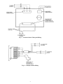
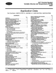
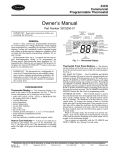
33CS
Carrier Comfort System
Pressure Sensor
Installation Instructions
Part Numbers 33CSPS--01 and 33CSPS--02
PACKAGE USAGE
PART NUMBER
33CSPS--01
33CSPS--02
USAGE
Applications not exceeding 0.5 in. wg
Applications not exceeding 2.0 in. wg
PACKAGE CONTENTS
ITEM
Metal Enclosure
Mounting Hardware
Circuit Board
Sensor Harness
Power Harness
QUANTITY
1
1
1
1
1
NOTE: The following items are field supplied:
• 2⁄10 in. ID plastic tubing, long enough to be run from pressure probe to sensor mounting location
• 18 gage, insulated, stranded wire, long enough to run from
pressure sensor to damper actuator
• 5 wire nuts
• static pressure pickup (part number 920147), for static pressure control applications
• velocity pressure probe (part number 920148 for 12 in.
device, 920149 for 18 in. device, and 920150 for 26 in.
device) for pressure independent control applications
GENERAL
The Carrier Comfort System pressure sensor is used for
static pressure control and pressure independent control in
VVTt systems. A field-provided pressure probe or pickup is
mounted in the VVT system air duct. The pressure sensor
reads the pressure from the pressure probe/pickup and sends
the information to the VVT system component (zone controller or bypass controller). The pressure information is used
to modulate the bypass or zone dampers when the system is
in static pressure control mode or pressure independent control mode.
NOTE: These sensors are designed for use with
33CSZC--01 zone controllers and 33CSBC--00 bypass
controllers.
2. Mount the metal enclosure base to the duct or a suitable
location. The operating environment for the sensor must
remain between 32 to 130 F. The length of the pressure
sensor tubing should not exceed 20 ft. The total length of
the wire between the pressure sensor and the associated
actuator should not exceed 100 ft. Recommended orientation of the sensor is with pneumatic tubing pressure ports
toward the bottom. When properly installed, the pressure
sensor will operate in any mounted position.
3. Push the pressure sensor circuit board down onto the standoffs until it locks into place.
4. The sensor wiring harness and power wiring harness should
be attached to the circuit board. If they are not attached,
push the plugs into the connector block on the pressure
sensor circuit board.
5. Install the static pressure pickup or velocity pressure probe
in the desired location. Run the field-supplied 2⁄10 in. ID
plastic tubing from the pressure pickup/probe to the pressure sensor. Static pressure control applications will only
use port P1. Port P2 is not used for static pressure control
applications and should remain open to the atmosphere.
Pressure independent control applications will use both
ports P1 and P2. See Fig. 1.
Do not wire pressure sensor or damper actuator while
power is connected. Electrical shock or death could
result.
6. Wire the pressure sensor to the damper actuator using the
sensor wiring harness, field-supplied wire, and 3 fieldsupplied wire nuts. Clip and secure the orange, red, and
black wires of the 6-wire section of the sensor wiring harness on the damper circuit board. They are not used. Wire
nut the white, blue, and green wires on the wiring harness of the pressure sensor to the field-supplied wiring
and run to the damper actuator. Connect them to the white,
blue, and green wires on the damper actuator wiring harness. See Fig. 1 and 2.
7. Wire the pressure sensor power wiring to a 24 vac, 5 va
power supply. See Fig. 1.
8. Install pressure sensor enclosure cover. The pressure sensor must be calibrated for proper operation.
INSTALLATION
IMPORTANT: Read these instructions completely before attempting to install the pressure sensor.
Perform the following procedure to install the pressure
sensor:
1. Attach the 4 plastic standoffs to the metal enclosure base
with the 4 screws provided.
Manufacturer reserves the right to discontinue, or change at any time, specifications or designs without notice and without incurring obligations.
Book 1 4
PC 111
Catalog No. 533-303
Printed in U.S.A.
Form 33CS-3SI
Pg 1
7-95
Replaces: New
Tab 11a 13a
Fig. 1 — Pressure Sensor Tubing and Wiring
Fig. 2 — Damper Actuator Wiring
2
6. When either noise level and/or drafts, due to supply airflow, becomes objectionable or the system static pressure
approaches the upper static pressure limit, use Zone Damper
Control to reopen the last zone damper that was closed.
Open zone dampers until the noise level and/or drafts in
every zone is acceptable or the unit supply air fan is able
to exceed the minimum airflow requirements. This determines the maximum supply air static pressure the bypass controller should allow for the system.
7. Calibrate the pressure sensor. To calibrate the pressure
sensor, select category 5, option 8. The current pressure
reading will be displayed on the bypass controller screen.
Use the left information buttons to adjust the value until
the pressure matches the system pressure on the manometer or Magnehelic gage.
8. Press the select button and modify the Auto Pressure Set
Point function (category 5, option 9). The current system
pressure will blink. Increment or decrement the value to
match the pressure reading of the Magnehelic gage. Press
the select button. The new system pressure set point will
be stored.
CALIBRATION
Static Pressure Pickup Calibration — To properly perform the calibration procedure, all associated devices with the VVTt system must be identified. The Communications Check option on the monitor thermostat (category 7, option 2) can be used to identify all network devices.
The nominal pressure for the 33CSPS--02 is 2.0 in. wg.
To calibrate the static pressure pickup, perform the following procedure:
1. Install a manometer or Magnehelic gage in parallel with
the pressure sensor. Tee the Magnehelic gage high port
into the high port of the pressure sensor. The low port
must be open. The high pressure port is indicated with a
P1 on the sensor.
2. Configure the bypass controller pressure sensor range (category 5, option 5). The default value of 2.0 in. wg is preset for use with the 33CSPS--02. Verify that it is set
correctly.
3. Select the Auto-Zero Enable function in category 5, option 6. Set the option to ON. The bypass controller will
automatically deenergize the equipment supply air fan.
The bypass controller will allow the pressure in the ductwork to dissipate during the Fan Off Delay. The Fan Off
Delay is configured in category 3, option 10. Two minutes will be added to the configured Fan Off Delay value.
During Fan Off Delay, the bypass controller will display
‘‘ZERO’’to indicate that the auto-zero function is in progress.
When the Fan Off Delay expires, the pressure sensor AutoZero Enable function will automatically calibrate the pressure sensor to zero. After the Auto-Zero Enable function
completes the pressure sensor re-zeroing, the bypass controller display will return the Auto-Zero Enable function
to OFF.
4. Set the System Setup Enable function (category 5,
option 7) of the bypass controller to ON. The bypass controller scans all associated devices, deenergizes the system heating/cooling equipment, closes the bypass damper(s), and opens all the zone dampers in the VVT system
to their Maximum Damper Position. The bypass controller also energizes the system supply air fan relay. This
option forces the system into a static condition so that a
stable system pressure can be obtained. By adjusting the
minimum and maximum damper positions at individual
zones, the system can be adjusted to balance airflow and
obtain an acceptable noise level. The bypass damper will
display the highest address found in its scan.
5. Use the Zone Damper Control function to close, one at a
time, the zone dampers farthest away from the equipment
supply air fan. Each time a zone damper is closed, check
the noise level and objectionable drafts in the zones that
remain open. Check the ability of the system supply air
fan to maintain supply airflow above the minimum required supply airflow. Use the left upper and lower buttons to scan through the devices found by the bypass
controller. The display will show the address and the damper
position, OP for open, CL for closed. Push both upper
and lower left buttons simultaneously to close or open
the selected damper.
Continue closing individual zone dampers until the noise
or drafts, due to increased supply airflow, becomes objectionable in any zone or until the equipment supply air
fan cannot maintain the minimum cfm requirements of
the unit.
NOTE: For systems utilizing temperature diversity, close
dampers at an opposing solar exposure while leaving the
other dampers open. Perform Step 2. The system should
be balanced while performing this task to assure designed airflow.
Velocity Pressure Probe Calibration — The nominal pressure for the 33CSPS--01 is 0.5 in. wg.
To calibrate the velocity pressure probe, perform the following procedure:
1. Install a manometer or Magnehelic gage in parallel with
the pressure sensor. Tee the Magnehelic gage high port
into the high port of the pressure sensor. The high pressure port is indicated with a P1 on the sensor. Tee the
Magnehelic gage low port into the low port of the pressure sensor. The low pressure port is indicated with a P2
on the sensor.
2. Configure the bypass controller pressure sensor range (category 5, option 5). The value of 0.5 in. wg should be set
for use with a 33CSPS--01. Verify that it is set correctly.
3. Configure the zone controller Velocity Pressure Probe Gain
option (category 5, option 6). The default value is 1.0.
4. Initiate the zone controller Auto-Zero function (category 5, option 7). Set the value to ON. The zone controller will position its damper full closed and measure
the velocity pressure. Once this is complete, the zone controller will automatically turn the option to OFF.
5. Initiate the zone controller Position Damper function (category 5, option 8). Adjust the damper position until the
desired velocity pressure is obtained at the manometer or
Magnehelic gage.
6. Calibrate the pressure sensor (category 5, option 9). Adjust the displayed value until it matches the measured value
of the manometer or Magnehelic gage.
7. Set the Minimum and Maximum Airflow Set Points (category 3, options 7 and 8). Set the Minimum Airflow Set
Point to allow acceptable fresh air requirements. Set the
Maximum Airflow Set Point so acceptable noise levels
are not exceeded.
8. Set the Damper Size option (category 3, option 9). The
value is set in square inches and is the cross sectional
area in which the probe is located.
9. Enable Pressure Independent Control (category 3, option
4). Set the value to ON.
3
Copyright 1995 Carrier Corporation
Manufacturer reserves the right to discontinue, or change at any time, specifications or designs without notice and without incurring obligations.
Book 1 4
PC 111
Catalog No. 533-303
Printed in U.S.A.
Form 33CS-3SI
Pg 4
7-95
Replaces: New
Tab 11a 13a