1
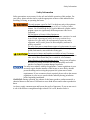
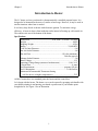
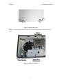
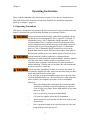
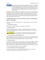
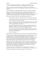
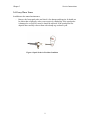
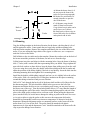
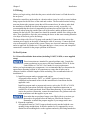
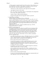
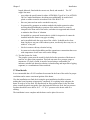
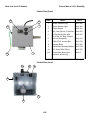
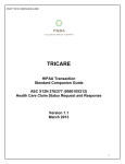
Revision H Updated 2014 Elston Manufacturing LC Heater Owners Manual Table of Contents Table of Contents Safety Information.............................................................................................................ii 1) Introduction to Heater...................................................1 2) Operating Instructions..................................................4 2.1 Operating Precautions..................................................................................................4 2.2 Running the Heater For the First Time or After the Unit Has Been Idle for a Long Time...................................................................................................................................5 2.3 General Recommendations for Loading and Heating Cargo........................................6 2.4 Normal Operation........................................................................................................7 3) Service Instructions........................................................8 3.1 3.2 3.3 3.4 Every Time You Walk By the Heater.........................................................................8 Every Time the Trailer is Loaded and Unloaded.........................................................8 Annually Before the Start of the Winter Season .........................................................8 Every Three Years......................................................................................................9 4) Troubleshooting...........................................................10 Problem A: Nothing happens when I turn on the heater...................................................11 Problem B: The green indicator light comes on but the blower does not run...................11 Problem C: Blower runs but heater fails to ignite............................................................12 Problem D: Heater usually ignites but sometimes does not..............................................13 Problem E: Heater ran down the battery at night while plugged in..................................13 Problem F: Carbon Deposits near Exhaust Outlet or Smoke from Exhaust Outlet...........14 5) Installation....................................................................15 5.1 Overview....................................................................................................................15 5.2 Unpacking the Heater and Gathering Supplies...........................................................16 5.3 Heater Placement ......................................................................................................16 5.4 Mounting....................................................................................................................17 5.5 Wiring........................................................................................................................18 5.6 Fuel System................................................................................................................18 5.7 Final details................................................................................................................21 6) Repair............................................................................22 6.1 6.2 6.3 6.4 6.5 Performing a Full Adjustment of the Burner.............................................................22 Checking the Operating Voltage of the Heater..........................................................22 Checking that the Regulator is Producing the Correct Pressure................................23 Replacing Blower......................................................................................................23 Removing combustion chamber................................................................................23 7) Parts List for HLC Heaters.........................................25 Valid for models H-LC-110 and H-LC-110V beginning with serial numbers H4914 i Safety Information Safety Information Safety precautions are necessary for the safe and reliable operation of this product. For your safety, please take the time to read the appropriate sections of this manual before installing, servicing, or operating the heater. Use only propane vapor for fuel. Use this heater only with regulators and tanks that provide propane vapor at 10.5 to 11 inches of water column. Use of a different fuel, a liquid withdrawal cylinder, and/or propane vapor at a significantly different pressure risks fire or explosion. Do Not Bypass or Remove Safety Equipment Although we understand temporary measures must sometimes be made to save a load, bypassing any safety device may result in fire or explosion. For your safety, do not temporarily bypass any safety equipment, and if you do, please fix these temporary measures as quickly as possible. Use only exact parts or manufacturer approved replacements for repair For proper function and safety, critical parts such as hoses, regulators, guards, and controls, must match the existing part. Do not service heater until unit has cooled for at least 15 minutes Heat exchanger and attached parts remain hot enough to cause burns after unit is shut off until they have cooled for a few minutes. Turn off power to the heater during service. Keep power off unless necessary for testing as heater can start unexpectedly and could pinch or cut fingers or sustain damage from tools. Use only in accordance with local regulations. Current regulations in your area may require that the installer of this heater or, more likely, that the person installing and servicing the propane fuel system meet certain requirements. If you are unsure what is required, please refer to the current regulations in your area or speak with the authority having jurisdiction before beginning installation. WARNING: During operation, the exhaust of this heater produces carbon monoxide, a chemical known to the state of California to cause birth defects and/or other reproductive harm. As always, apply common sense and beware the perils of ignorance. If you are not sure it is safe or do not have enough knowledge to know if it is safe, then do not do it. ii Chapter 1 Introduction to Heater Introduction to Heater The LC heater you have purchased is a thermostatically controlled propane heater. It is designed to be mounted on the nose of a trailer to heat cargo. However, it may be used in similar situations where heat is needed. It is a heavy duty forced air heater with electronic ignition. To maximize energy efficiency, it heats air drawn from inside the trailer instead of heating up cold outside air. The exhaust exits out of the bottom of the heater. Specifications Dimensions..............................................36 in wide x 16 in tall x 9 in deep Weight..................................................................................................80 lbs Shipping Weight..................................................................................82 lbs Rating........................................................................................35,000 BTU Cold Air Inlet Diameter...........................................................................6 in Hot Air Outlet Diameter..........................................................................4 in Hot Air Flow.................................................................150 cfm (minimum) 200 cfm (typical) Exhaust Outlet Diameter.........................................................................2 in Rated Voltage........................................................................................12 V Operating Voltage Range (measured at thermostat)..................11.0-13.0 V Current Draw.....................................................................................8 amps Fuel Requirement...............................................................propane (LP gas) Fuel Consumption..................................................................1.6 lbs/hr max Maximum Recommended Thermostat Setting (call for advice on higher temperatures)............................................70F All HLC heaters have two standard parts: the heater and the control box. Let’s begin with the heater. The heater cover can be opened by grasping each handle with your thumb pointing in and turning your hands a quarter turn so your thumbs point straight down. See Figure 1 for an illustration. 1 Chapter 1 Introduction to Heater Figure 1: Opening the Heater When you look inside the heater you will see the major components shown in Figure 2 below. Figure 2: Inside of LC Heater 2 Chapter 1 Introduction to Heater Mounted at eye level on the trailer, you will see a gray control box (see Figure 3), with a rocker switch and two indicator lights. The rocker switch turns the heater on and off, the top (green) indicator lights when the heater is getting power, and the bottom (amber) indicator lights when the ignition system is waiting for the heater to light or unsuccessful in lighting the heater (See the section on troubleshooting for more information). The 110V plug located on the control box allows you to run the heater without attaching the trailer to a semi tractor or to run the heater through the night without running down your vehicle’s battery. The circuit breaker, power supply, and other electronics for the 110V standby are mounted inside the heater shell. Figure 3: Control Box 3 Chapter 2 Operating Instructions Operating Instructions Please read the important safety information on page ii if you haven’t already done so. This guide assumes the heater has already been installed. For installation instruction please go to chapter 5 (page 15). 2.1 Operating Precautions This heater is designed to heat and provide freeze protection of cargo in trailers and truck bodies. It should not be used for heating buildings or recreational vehicles. To prevent explosions and comply with federal regulations, do not use this heater when transporting Class 1 (explosive), Division 2,1 (flammable gases), Class 3 (flammable liquids) materials. If you wish to transport Class 1 (explosive) materials, the propane tanks must be emptied or removed and the power to the heater turned off and locked out. If you wish to transport Division 2.1 (flammable gases) or Class 3 (flammable liquid) materials, the valve on the propane tank must be closed, the hose to the propane tanks must be disconnected, and the power to the heater turned off and locked out. Carbon monoxide could be produced by a damaged heater. Symptoms of carbon monoxide include headache, dizziness, burning eyes and nose, nausea, and dry mouth or sore throat. If you experience these symptoms, immediately seek fresh air and seek medical attention. Ventilate the area to reduce the carbon monoxide to safe levels before reentering. Correct any leaks immediately as they are a serious fire hazard. If you smell the slightest gas odor, do not use the heater until you have found and fixed the source of the leak. If you smell gas or suspect flammable vapors may be present (from a spilled flammable liquid, etc.) in an enclosed area, take immediate action. Follow your company's procedure if one is established. Otherwise: • Do not do anything that could ignite the mixture including operating an electrical switch, disconnecting an extension cord, or using your phone. Do not light matches or any other source of flame. • Get everyone away from the area immediately. • Call your fuel supplier and/or the fire department • Do not reenter the area until the area has been aired out and declared safe. • Have a properly trained service person repair any leaks and bring the heater back into service. 4 Chapter 2 Operating Instructions Do not disconnect power from the running heater except in an emergency. Stopping the heater before it has finished its cool-down cycle will cause it to wear out significantly faster. Wait to use the switch on the side of the heater until the fans have stopped. Please turn down the thermostat or turn off the propane during normal operation to force the heater to enter its cool-down cycle. Propane has a chemical added to give it a distinctive odor. If you are not familiar with that odor, please contact your local LP supplier. They can provide you with a scratch and sniff pamphlet. Use extra caution if you smoke or strong odors are present as this can make the odor difficult to notice. Like most other odors, extended exposure can reduce your sensitivity to the smell. Since LP gas is heavier than air, please remember that the odor will be stronger at lower levels. 2.2 Running the Heater For the First Time or After the Unit Has Been Idle for a Long Time Whenever you need to verify that the heater is working properly, please follow the four steps below. 1) Check inlets and outlets Check that the air inlets and outlets are undamaged and unblocked. 2) Check fuel system Check that the propane tank(s) are securely mounted and the gas lines and fittings between the propane tank(s) and the heater are tight and undamaged. Turn on the valve on the propane tank(s). If you smell propane, immediately discontinue operation of the heater until the source of the leak has been found and fixed. 3) Set the thermostat to the maximum value If the temperature is above 80 or 90 degrees, you may not be able to turn the thermostat high enough for the heater to start in the next step. If you wish to continue setting up the heater you will need to chill the thermostat probe or wait for a cooler day. 4) Turn on the heater The heater will start and, after a few seconds, ignite. The red indicator light in the control box will turn on until the heater has ignited. If the heater doesn’t ignite right away, the ignition system will try to ignite the heater again after a short delay. If the heater still doesn’t ignite after a few minutes (the red indicator light will turn on and stay on), please refer to the troubleshooting guide to help fix the problem. 5) Set the thermostat to the desired temperature. Your heater is now ready for use. The heater will automatically turn on and off as necessary to maintain the desired temperature in the trailer. 5 Chapter 2 Operating Instructions 2.3 General Recommendations for Loading and Heating Cargo This section contains some general suggestions on loading cargo and setting the thermostat on the heater. However every application is unique so experience will be your best guide. These recommendations assume that the thermostat probe is mounted on a nonmetal surface on the front wall of the trailer about 2 to 3 feet off the floor and the walls and ceiling have at least an inch of insulation. Additional insulation will reduce fuel consumption, even out the temperature in the trailer, allow the same trailer temperature in much lower outdoor temperatures and is often required for adequate performance. This heater operates most effectively when the following things are true: • Cargo is loaded so that there is room for hot air to travel the length of the trailer. • Cargo is loaded so there are areas for the cold air to settle and unobstructed paths for this air to return to the front of the trailer. • Cargo is standing away from all the walls and setting on insulating surface off the floor, like a wooden pallet. This is especially important for the rear walls since it tends to be the coldest place in the trailer. • An extended cold air intake. If the cold air intake is extended so that the air is pulled from a couple feet off the floor, the circulation in the trailer will be better and there will much more even temperature throughout the trailer. • The seals for any openings should be in good condition. Significant amounts of heat can be lost through a poorly sealed door making the cargo in the rear of the trailer much colder than the rest. • The trailer is insulated. If the heater has everything it needs to operate effectively, start by setting the thermostat 8 to10 degrees above the desired minimum temperature. This assumes the temperature of the cargo is within 10 –20 degrees of the minimum temperature. If the cargo is considerably warmer than the minimum temperature, like cargo in a 70 degree warehouse that needs to be kept above freezing, you may need to set the thermostat higher since some areas of the trailer can cool considerably faster than others. To get started, try setting the thermostat an additional 3 degrees warmer (for a total of 11-13 degrees). If the cargo is not loaded to allow good air circulation, the trailer is uninsulated, or you are hauling bulk cargo, setting the thermostat will be more difficult. The trailer will have large cold pockets near the floor of the trailer because of limited ways for the heat to circulate. There are no definite recommendations but try starting with a setting 20 degrees above the desired minimum temperature. If you load cargo in areas of the trailer that are naturally warmer, you can set the temperature a few degrees cooler than what is recommended above. The warmest area of the trailer is the front 30 feet of the trailer more than 2 ½ feet off the floor. 6 Chapter 2 Operating Instructions 2.4 Normal Operation 1) Check propane supply Check that the propane tank(s) are securely mounted and contains fuel. Check that the fitting connecting the tank to the gas system is tight. Turn the propane tank valve on. If you smell propane, immediately discontinue operation of the heater until the source of the leak has been found and fixed. 2) Set the thermostat Set the thermostat to the desired temperature. Please refer to the previous page for recommendations on setting the temperature. 3) Turn on the heater Use the rocker switch in the control box to turn the heater on. Your heater is now ready for use and will automatically run as necessary to maintain the trailer at the desired temperature (just like a home furnace.) Under normal operation, you will hear the heater periodically ignite, sometimes with a noticeable but not loud pop. 4) Turn off the heater If possible, do not turn off the heater when it is running. If you need to turn off the heater while it is running, it is recommended that you first turn off the heater by turning off the propane, wait until the fan has stopped, and then turn off the heater. Turning off the heater with the power switch while it is running is not inherently dangerous, but it will significantly reduce the life of some of the components inside the heater. 7 Chapter 3 Service Instructions Service Instructions 3.1 Every Time You Walk By the Heater • Check the exterior of the heater and the exterior gas lines for damage • Check that the handles are in the fully closed position • Check that the heater is not smoking or producing soot (if it is refer to the section on troubleshooting) 3.2 Every Time the Trailer is Loaded and Unloaded • Check the return air inlet and the heater outlet for damage and obstructions and the thermostat probe for damage • Check that the gas and electrical lines are secured to the trailer and undamaged 3.3 Annually Before the Start of the Winter Season • Carefully inspect the propane tank, regulator, and fuel lines for leaks or damage. Replace any damaged components and fix any leaks. • Check the return air inlet and the heater outlet for damage and obstructions and the thermostat probe for damage. Remove any obstructions and repair any damage. • Check that all mounting bolts and screws are tight and check that all electrical wiring is securely attached and undamaged. Also check that electrical fittings going into the heater and control box are tight. • Remove the burner cover and inspect the burner and the inside of the combustion chamber. Check that the screws for the spark electrodes are tight and the wires to the spark probes are securely attached. • Clean any dust or dirt from around the blower and the air inlets and outlets. • Check the exhaust outlet for carbon deposits and clean the heat exchanger if significant deposits (more than a film) are present • Start up and run the heater for a couple of minutes to check that everything is in working order. 8 Chapter 3 Service Instructions 3.4 Every Three Years In addition to the annual maintenance, • Remove the front spark probe and check it for damage and deposits. It should not be darker than a light gray or have an excessively rounded tip. If the spark probe is damaged or excessively round, it should be replaced. If the spark probe has deposits then carefully remove them with a damp rag or abrasive pad. Figure 4: Spark Probe in Excellent Condition 9 Chapter 4 Troubleshooting Troubleshooting For your safety, the propane should always be turned off when troubleshooting this product except when required to test the function of the heater. Always keep the power to the heater off when working inside the heater except when required to test the function of the heater. See the appendix for wiring diagrams. If this guide doesn’t fix your problem please contact the company where you purchased the heater. If you are unable to contact them or you need additional help, please contact Elston Manufacturing at 1-800-845-1385. Description of Normal Operation To aid in troubleshooting, it is often useful to have a clear description of the normal operation of the heater to better describe what is wrong with it. Begin with the heater off, the propane turned on, and the thermostat set to its minimum setting. Turn on the heater at the control box. The green indicator light will come on. Next turn up the thermostat to turn on the heater (this will be unnecessary below 20 F). The red indicator light will come on and the blower will start. After a 15 to 30 second delay, the gas turns on and a faint clicking noise is heard as the spark lights the heater. The heater will run until the trailer reaches the temperature set on the thermostat. The gas will turn off but the blower will run for an additional 2 to 3 minutes to cool down the heater. Table 1: Timing Charts 10 Chapter 4 Troubleshooting What is wrong with the heater? A. Nothing happens when I turn on the heater B. The green indicator light comes on but the blower does not run C. Blower runs but heater fails to ignite. D. Heater usually ignites but sometimes does not. E. The blower does not run after the gas turns off F. The heater ran down the battery while plugged in at night. G. The heater is producing smoke or carbon deposits are visible near the outlet of heater. Problem A: Nothing happens when I turn on the heater Does the green indicator light in the control box come on momentarily when you turn on the heater? Yes Check the electrical connections in the heater and control box for loose connections and the blower in the heater for obstructions. To check for obstructions, loosen the hose clamp on the blower and slide it off of the combustion chamber. If the there are no obstructions, the blower should turn freely. If the blower doesn't turn freely, it needs to be replaced. No If the heater is running off trailer power, check the fuse supplying power to the trailer and the 10 Amp circuit breaker on the electrical cover. If the heater is running off the 110V standby, check that the extension cord is properly plugged in. Also check the fuse in the circuit supplying power to the 110V standby and the 3 Amp circuit breaker on the electrical cover. Problem B: The green indicator light comes on but the blower does not run Do you hear a faint clicking noise fifteen to thirty seconds after you turn up the thermostat? Yes Focus your troubleshooting on the blower and the associated circuitry by checking the following list of items: 1) Check that the two wires to the blower are firmly attached and there are no obstructions in the blower. To check for obstructions, loosen the hose clamp on the blower and slide it off of the combustion chamber. If there are no obstructions, the blower should turn freely. If the blower doesn't turn freely, it needs to be replaced. 11 Chapter 4 Troubleshooting 2) Check the wiring connected to the wiring tray. Look for loose, corroded, or damaged wiring especially at the power and fan terminals on the back of the ignition module. 3) Remove the cover to the thermostat and check that the heater is receiving at least 11.0 VDC if hooked up to battery power and 14 VDC when powered by the 110V standby. Voltage will not be this low unless there is a problem in the electrical system between the heater and the vehicle or the battery is run down so much the vehicle won't start. Start by looking for loose or corroded connections. 4) If none of the above solve the problem, remove the blower and connect it directly to the battery. If the blower runs, the ignition relay should be replaced. No This indicates the sail switch is stuck open or the voltage to the heater is very low. With the power to the heater off, check the resistance between the two terminals on the sail switch (or on older models with three terminals the wires should be attached to the the two terminals on the right side). If this resistance is less than 100 ohms or so the sail switch is either stuck open or bad. Remove the blower and adjust the sail switch if it is stuck. If it isn't stuck replace it. If the sail switch wasn't the problem, either there is a bad connection in the wiring supplying power to the heater or the device supplying power to the heater has significant problems. If the heater is running off the 110V standby, the 110V standby may need to be serviced. If not, check the condition of the vehicle battery. Problem C: Blower runs but heater fails to ignite Listen carefully. You should hear a faint clicking noise fifteen to thirty seconds after the blower starts. If you do, then: 1) Check the fuel system, especially that the propane tank(s) contain fuel and valve is open on the tank(s). Confirm that the heater is getting fuel. 2) Check that the primary spark probe is connected to the top of the ignition module and the quick connect on the end of the spark probe wire is securely connected to both the ignition coil (see figure 6) and the spark probe wire. Check that the wire for secondary spark probe is connected to the front of the combustion chamber. 3) Remove the cover to the thermostat and check that the heater is receiving at least 11.0 VDC while the blower is running. A voltage below 11 VDC typically indicates a low battery or a problem in the electrical system between the heater and the vehicle. If the voltage is this low, start the vehicle and try starting the heater again. If the voltage is low with the vehicle running, there is a problem in the electrical Figure 5: Sail Switch 12 Chapter 4 Troubleshooting system between the heater and the vehicle. Start by looking for loose or corroded connections. 4) Check the sail switch on the blower. First check if the wires are attached. With the power to the heater off, check the resistance between the two terminals on the sail switch (or on older models with three terminals the wires should be attached to the the two terminals on the right side). Push the front of the switch closed to simulate the blower running as shown in figure 5. The resistance should be less than 1 ohm. If not replace the sail switch. Also check for a good connection between the rightmost terminal on the sail switch (see figure 5) and ground. This resistance should be less than 1 ohm. If it is not, remove the cover to the combustion chamber and check the wiring to the high temperature limit switch. If the wiring is attached and in good condition, check the resistance across the limit switch. If the resistance is more than 1 ohm replace the switch. 5) Check the primary spark probe. Remove the burner cover from the combustion chamber and the spark probe on the right side of the burner. The metal tip of the spark probe should only be slightly rounded, the spark probe should only have light deposits on the insulator, and the ceramic insulation should be undamaged. If the spark probe is damaged or excessively round, it should be replaced. If the spark probes has only deposits, carefully remove them with a damp rag or abrasive plastic pad. Problem D: Heater usually ignites but sometimes does not Check that the valve on the propane cylinder is fully open. Occasionally, a tank will fail to supply enough gas to the heater unless the valve is fully open. Is any extra ductwork connected to the exhaust or air inlets or outlets? Yes. The heater should have less than 15 feet connected to the inlet and outlet in the trailer. Any additional pipe connected to the exhaust should be 3 inches in diameter and less than 8 ft long. Disconnect all ductwork to the heater to see if this corrects the problem. No Carefully check all the inlets and outlets and blower for debris and obstructions. Follow the trouble shooting suggestions for problem B, paying special attention that the heater is getting sufficient voltage while the heater is under load and the spark probes are in good condition. Problem E: Heater ran down the battery at night while plugged in When the 110V standby has problems the heater will switch back to 12 V power. Plug in the 110V standby and restore power to the heater. If the green light on the control box comes on momentarily, carefully check the wiring in heater for loose connections. If the green light on the control box never comes on, check the power supply. Check to see if the green LED on the power supply is lit. If so, use a multimeter to see if 12 VDC is 13 Chapter 4 Troubleshooting coming from the terminals on the power supply. If the green LED on the power supply is not lit and/or the voltage from the terminals of the power supply is not 12 VDC, then the power supply needs replacement. If you don’t find any problems, the control box or the electrical tray assembly needs to be inspected and serviced. Problem F: Carbon Deposits near Exhaust Outlet or Smoke from Exhaust Outlet Under normal use, the heater will deposit very little, if any, carbon near the exhaust outlet. These deposits are often the first sign of a problem with the heater and an indication the heater should be shut off. In addition, this problem often shows up first when the vehicle is not running. These deposits typically indicate that one of the openings in the heater is obstructed or the heater is not receiving enough voltage while it is running. 1) Check if the heater is running off of the battery only (i.e. the vehicle is not running). If the battery is significantly run down, the heater cannot receive enough voltage to operate properly. Running the heater for less time on the battery or starting the vehicle should correct the problem. If this occurs even when the heater has been running off the battery for less than a couple hours, refer to the troubleshooting suggestions for when the vehicle is running. 2) Check if the heater is running off the 110V standby. Check that none of the inlets or outlets to the heater are blocked or any ductwork is damaged. The voltage at the thermostat should be approximately 12V when the heater is running with the 110V standby plugged in. If this problem occurs when the vehicle is running or after less than an hour of running on the battery, check the following: 1) Check that none of the inlets or outlets to the heater are partially blocked or any ductwork leading to or from the heater is damaged. 2) Check that the heater is receiving a voltage of at least 11VDC at the thermostat while the blower is running. A voltage below 11 VDC typically indicates a problem in the electrical system between the heater and the vehicle. Start by looking for loose or corroded connections. 3) Check that the regulator is producing the correct pressure of 10.5-11 inches water column. This should have been done during installation. Therefore, this is necessary only if you have no records that it was done during installation or it has been a few years since the heater was installed. After you have corrected the problem, remove any carbon deposits present in the exhaust tubing. If problem reoccurs, the burner air inlet ring can be adjusted so the heater will run leaner. Please consult the factory for additional instructions. 14 Chapter 5 Installation Installation Improper installation of this heater creates a substantial safety hazard including the risk of property damage, fire, and/or death. Compliance with local regulation is the responsibility of the installer. Current regulations in your area may require that the installer of this heater or, more likely, that the installer of the propane system fueling this heater meet certain requirements and/or that the completed installation be inspected. If you are unsure what is required, please refer to the current regulations in your area or speak with the authority having jurisdiction before beginning installation. 5.1 Overview The choices you make in installation have huge effects on the safe and reliable operation of this heater. There are five primary issues to focus on: 1. Safe and robust installation of the propane fuel system 2. Safe and robust installation of the electrical system 3. Secure mounting of all parts against long-term vibration 4. Keeping out water (and its corrosive effects) 5. Ensuring adequate and consistent air flow to the heater These purpose of these instructions is to aid you in installing a fully functional heater that is safe and secure under both normal condition and, as much as possible, during an accident. However these instructions are not a substitute for personal knowledge and experience with installing propane and/or electrical systems. Please do not install those areas of the heater unless you have personal knowledge and experience in these areas. These instructions were written with the latest standards for the US and Canada in mind and are intended to guide you in an installation that meets these standards. At the time of writing, the latest standards were the 2014 edition of NFPA 58, the Liquefied Petroleum Gas Code and the 2010 edition CSA-B149.5-10, Installation Code for Propane Fuel Systems and Tanks on Highway Vehicles. However, if the regulations that apply in your area conflict with these installation instructions the regulations should always be followed instead. Throughout this guide, the word “must” is used for any instruction that if not followed would create a safety hazard and/or yield an installation that would not comply with current standards. An instruction with the word “should” is necessary either for the proper functioning of the product or improves the long-term safe operation of the product. If you are unable to follow any instructions with the words “must” or “should”, please contact us and/or the authority responsible for regulating or approving your installation to discuss how your installation can be still be completed in a way that is functional, safe, and compliant. Finally, an instruction that recommends indicates an instruction designed to maximize the working life of the product, simplify installation, or improve the appearance of the installed product. 15 Chapter 5 Installation 5.2 Unpacking the Heater and Gathering Supplies Parts Needed for Installation shipped with Heater: • Recirculating Style H-LC Heater • 6 fender washers - ½”x2” • Template for mounting holes • 6 feet self stick rubber seal • Post -installation checklist • (3) stainless steel eye straps for 1/2” conduit between control box and heater • (optional) Series 32A laydown propane tank, X-1025 bottle holder, or X-1050 bottle holder • (optional) Installation kit for propane fuel system Additional parts required: • (6) ½” diameter grade 5 bolts 1 to 1 ½ inches longer than the thickness of the front wall of the trailer with 12 flat washers, 6 lock washers and 6 nuts to match • Sheet metal screws for mounting control box and eye straps • Brackets and clips for attaching fuel lines, electrical lines, and thermostat probe to the trailer walls • Suitable propane fuel line and fittings or HLC propane installation kit • 12” of 4” double walled duct pipe (optional) 5.3 Heater Placement The primary consideration for the placement of the heater is the location of the hot air outlet and the return air opening. These openings cannot be blocked with freight or other objects. For good circulation and the most even heat, cargo should not be within 6 feet straight out from these openings (it may be below them). As a result, the heater should be mounted high enough to allow this without sacrificing too much cargo space. Mounting the heater with the hot air outlet ¾ of the way up from the bottom of the trailer (or slightly less) is a good compromise between lost cargo space and the reduced air movement thru the trailer that comes from mounting the heater too close to the top of the trailer. The heater must also be mounted where there is enough clearance to open the door when the trailer is hooked up. All these considerations are shown in Drawing 1 below. 16 Chapter 5 Installation B C Back of Tractor A D Trailer A: Mount the heater about ¾ of the way up on the front of the trailer (see previous paragraph) B: Mount in a position there is enough clearance to open the door of the heater C: 6ft distance cargo should stand off from hot air outlet. Cargo below hot air outlet can be much closer (see D below) D: Small space with no cargo at front of the trailer for circulation and optional cold air inlet Drawing 1: Placement of Heater 5.4 Mounting Tape the drilling template in the desired location for the heater, checking that it is level and flat against the trailer. Center punch the two large holes and the mounting holes indicated on the template. Remove the template and identify the size of the holes on the trailer. If you are cutting the larger holes with a jigsaw or saber saw, use a compass to mark the circles on the trailer Drill all holes to the size indicated on the template. Mount the weather seal on the back of the heater around the perimeter of the heater, an inch or two from the edge. Lift the heater into place and align it with the mounting holes. Once the heater is lined up, slide ½” bolts (with a washer) into the top mounting holes you drilled. Finger tighten the nuts with lock washers on these bolts to keep the heater from pulling away from the wall. If you are using duct work, place the double walled duct tubing on the hot air outlet and adjust the position of the heater slightly if the hole is not lined up. Insert the bolts into the remaining mounting holes and tighten all six mounting bolts. Install the the double walled tubing (optional) and cut it so it is slightly below the surface of the trailer. Slide a few small pieces of fiberglass insulation in the spaces remaining around this tubing to insulate it and prevent vibration. Drill a 9/16” hole through the back wall of the heater shell and the wall of the trailer for the thermostat probe. The hole should be drilled in the open area to the left of the thermostat and below the blower (on a recirculating style heater you may need to move the blower out of the way). Trim the included plastic tube to 1/8” more than the length of the hole through the wall of the trailer. Insert the trimmed tubing and fix and seal it into place with a high quality sealant such as a silicone caulk. When pulling the thermostat prove into the trailer, be careful not to damage the tubing or probe on the end. Never use a vise-grip or pliers to grip the probe as this can cause the temperature dial on the thermostat to permanently switch at an incorrect temperature of otherwise break the thermostat. Mount the thermostat probe on a nonmetal surface on the front wall of the trailer about 2 to 3 feet off the floor. The probe should be attached with plastic tinnerman-style clips and the thermostat “wire” should be attached to the front wall with clips to prevent damage from vibration. 17 Chapter 5 Installation 5.5 Wiring Before you begin wiring, check that the power switch to the heater is off and the trailer has no power. Mount the control box on the trailer in a location where it may be easily accessed without being exposed to the full force of the wind and weather. The box and associated wiring must not obstruct the propane system that will be mounted next. In order to make both the installation of both the electrical and propane system as easily as possible, it is recommended that the electrical components be mounted toward the right side of the front wall (when facing the outside front wall of the trailer) and the propane system be mounted on the left side. The control box should be mounted with the wire exiting on the sides. There should be a dip in the wire entering the boxes so that water running down the wire drips off before it gets to the fittings. The heater ships with 4 feet of 14-gauge cord attached. Connect the white wire to the constant power supply on the trailer, trimming the cable if necessary. Connect the black wire to the negative or ground of the system. Always use electrical connectors, fittings, and wire approved for outdoor use. Using parts that give a clean, secure, and waterproof connection is essential for the proper operation of the heater. 5.6 Fuel System 5.6.1 General Installation Instructions (including X-1025, X-1050, or user supplied setup) These instructions are intended for general guidance only. Consult the current regulations in your area or the latest standards, NFPA 58 for the United States or CSA 149.2 for Canada, for exact requirements. Before you begin mounting any components, it is recommended that you determine the approximate mounting location of all components to ensure that all parts can be connected with the available lengths of hose and tubing. The recommended order of installation is: 1) Install the propane tanks or propane tank carriers. All propane tanks must be “DOT” or “ASME” approved, setup for vapor withdrawal,and mounted in line with the manufacturer's instructions and the applicable code. Install the propane tank or propane tank carrier, such as the X-1025 or X-1050, following the instructions included with product. Installation instruction are available for all tanks purchased from Elston Manufacturing. If your tank or tank carrier does not have instruction, contact the manufacturer for guidance and refer to the installation code that applies in your area. New tanks that are purchased empty come filled with air or an inert gas that needs to be purged before the tanks are filled for the first time. Remember to inform the propane supplier if your empty tank is new. 2) Mount the regulators All regulators must be CSA/UL approved and securely attached with the vent opening facing straight down. It must be attached so it is supported by screws attached to the mounting holes on the regulator and not by the fittings attached to 18 Chapter 5 Installation it. If the regulator is mounted on the front wall it must have either a durable cover or be installed in an enclosure. If the regulator is mounted at or below the floor level of the trailer, it must be installed in an enclosure that is • sufficient size to allow connection to and replacement of the regulator • vapor-tight to the interior of the trailer • have 1 in2 or larger vent opening within 1 in of the bottom of the compartment and 2 in below the regulator vent opening • contain no flame or spark producing equipment • designed and mounted with as much ground clearance as practical 3) Install all hoses and fittings Attach all fittings to the regulators, heater, and the tanks. The POL fitting attached to the tank must have a built-in excess flow valve. All fittings including bulkheads must have wrench flat or similar way that each fitting can be individually tightened or loosened (close nipples are not allowed). The threads in fittings must be a tapered pipe thread and sealed with a joint sealant approved for this use. Attach the hoses as necessary. All hose assemblies must carry a CSA/UL approved label and be 36” or shorter. 4) Install the copper propane line The copper line should be run as directly as possible between components while maintaining adequate clearance from the exhaust system and areas with a high risk of impact damages such as above the tires. Once the route for the copper tubing is determined, any necessary holes in the frame or floor supports can be drilled and installed with grommets and the tubing can be pulled into place, trimmed to length, deburred, fitted with the correct nut, flared, and attached. The 3/8” copper line must: • meet either the specification for either ASTM B 88 (Type K or L) or ASTM B 280. In Canada installations, the tubing must additionally be marked and plastic or rubber coated in accordance with CSA-B149.5-10. • Have no joints and can not be extended in any way • be protected by grommets or another method with similar protection when traveling through bulkheads or portions of the trailer frame, be securely clamped to the front wall of the trailer, and otherwise supported and secured to minimize the effects of vibration • be installed in a protected location that is visible for inspection. It cannot be installed inside the frame or any pipe or tubing. • not be installed inside the cargo area of the vehicle. It should not be closer than 4 inches to any part of the exhaust system, run directly above any tire, or within 6” of any tire. • Not be in contact with any electrical wiring • be connected so that slight shifting and the expansion or contraction that occur with temperature do not cause stress on the fittings 19 Chapter 5 Installation 5) Test the System for Leaks The propane system must be tested for leaks before the operation of the heater is tested or it is placed into operation. This leak test must use a pressure gauge or manometer. If a leak is found, it must be located using a combustible gas indicator, suitable leak detection solution, isolated testing and inspection of piping segments, or a combination of these methods. 5.6.2 Installation Instructions for Series 32A Laydown Tank with H-LC-S32I Installation Kit These instructions are intended for general guidance only. Consult the current regulations in your area or the latest standards, NFPA 58 for the United States or CGA 149.2-10 for Canada, for exact requirements. Before you begin mounting any components, it is recommended that you determine the approximate mounting location of all components to ensure that all parts can be connected with the available lengths of hose and tubing. See the parts list for H-LC-S32I installation kit for the order that the parts are connected and the length of included parts. The recommended order of installation is: 1) Install the propane tanks or propane tank carriers. Install the Series 32 propane tank following the instructions included with product. Additional copies of the instructions are available from Elston Manufacturing. New tanks that are purchased empty come filled with air or an inert gas that needs to be purged before the tanks are filled for the first time. Remember to inform the propane supplier if your tank is new. 2) Attach hoses and fittings Attach all fittings to the regulators, heater, and the tanks. All joints with tapered pipe thread must be sealed with a joint sealant certified for this with propane vapor. See the parts list for the H-LC-S32I installation kit for a list of fittings that connect to the heater, regulators, and the tanks. 3) Mount the 2 Stage Low Pressure Regulators The 2 stage low pressure regulator (HLC-624) and enclosure (HLC-940) should be mounted near the propane tank with as much ground clearance as practical at the correct distance for the HLC-932 hose to attach between the regulator and the Series 32 tank. The regulator is attached to the enclosure with four #8/32 thread cutting screws, #8 lock washers, and #8 washers. The enclosure must be bolted to a trailer support with the vent slots toward the bottom. 4) Attach the hoses as necessary to the regulator, Series 32 tank, and heater. 5) Install the copper propane line The copper line should be run as directly as possible between components while maintaining adequate clearance from the exhaust system and areas with a high risk of impact damages such as above the tires. The end of the copper line connecting to the heater should designed such that the HLC-908 hose can attach between the end of the tubing and the heater. Once the route for the copper tubing is determined, any necessary holes in the frame or floor supports can be drilled and installed with grommets and the tubing can be pulled into place, trimmed to 20 Chapter 5 Installation length, deburred, fitted with the correct nut, flared, and attached. copper line must The 3/8” • meet either the specification for either ASTM B 88 (Type K or L) or ASTM B 280. In Canada installations, the tubing must additionally be marked and plastic or rubber coated in accordance with CSA-B149.5-10. • Have no joints and can not be extended in any way • be protected by grommets or another method with similar protection when traveling through bulkheads or portions of the trailer frame, be securely clamped to the front wall of the trailer, and otherwise supported and secured to minimize the effects of vibration • be installed in a protected location that is visible for inspection. It cannot be installed inside the frame or any pipe or tubing. • not be installed inside the cargo area of the vehicle. It should not be closer than 4 inches to any part of the exhaust system, run directly above any tire, or within 6” of any tire. • Not be in contact with any electrical wiring • be connected so that slight shifting and the expansion or contraction that occur with temperature do not cause stress on the fittings 6) Test the System for Leaks The propane system must be tested for leaks before the operation of the heater is tested or it is placed into operation. This leak test must use a pressure gauge or manometer. If a leak is found, it must be located using a combustible gas indicator, suitable leak detection solution, isolated testing and inspection of piping segments, or a combination of these methods. 5.7 Final details It is recommended that a X-850 ventilator be mounted in the front of the trailer for proper ventilation and to ensure consistent ignition of the heater. Give the installation one final check using the post-installation checklist to ensure nothing has been forgotten or improperly completed. If everything looks adequate, the heater is ready to be test fired. For instructions on firing up the heater for the first time please consult the quick start guide. Once the heater has been test fired, the low pressure regulator should be set to deliver 10.5” - 11” W.C. pressure to the heater while it is running. The installation is now complete and the heater can be placed in service. 21 Chapter 6 Repair Repair 6.1 Performing a Full Adjustment of the Burner Tools required: Phillips screwdriver, two needle-nose or similar pliers, wrench set , socket set (optional), pipe dope or sealant 1) Turn off power and gas to the heater. 2) Remove the cover to the combustion chamber by removing the four nuts holding it. 3) Remove the gas fittings attached to the burner. 4) Remove the spark electrode on the bottom of the burner. 5) Remove the burner from the combustion chamber by removing the bolt that holds it in place. 6) Blow out the combustion chamber and the burner with compressed air. Clean any more stubborn deposit off of the burner. Since removal of the combustion chamber and burner is rarely necessary it is not unusual to see modest deposits inside the heater. 7) Reinstall the spark electrodes from the bottom of the burner 8) Check that the gap between the two spark electrodes shown in Figure 6. If the gap is larger that 1/8” then adjust the gap to the correct width. Use care when making adjustments as the insulator is fragile. 9) Reinstall the burner into the combustion chamber. Figure 6: Spark Gap 6.2 Checking the Operating Voltage of the Heater Tools required: Phillips screwdriver and a multimeter 1) Turn off power to the heater at the control box using the rocker switch. 2) Remove the cover to the thermostat shown in the . 3) With a multimeter set to VDC, check the voltage between one of the brass screws on the thermostat and the electrical tray. Refer to the troubleshooting guide for correct range of voltages. Figure 7: Thermostat 22 Chapter 6 Repair 6.3 Checking that the Regulator is Producing the Correct Pressure Tools required: Low pressure gas gauge with a dial in inches of water column, set of wrenches 1) Turn off gas and power to the heater. 2) If necessary, add fittings to allow the gauge to read the gas pressure in the line between the regulator and the heater while it is hooked up to the heater. 3) Connect the gauge to the fittings and turn on the gas. The gauge should show a pressure between 11 and 12” water column. 4) Start the heater. The pressure should drop slightly and stabilize at approximately 11” water column. If necessary, adjust the regulator to achieve the correct pressure under load. 6.4 Replacing Blower Tools required: Standard (slotted) screwdriver 1) Disconnect wiring from blower and sail switch on top of fan. Carefully note where each connection was attached. 2) Remove screw holding blower to blower support bracket. 3) Loosen hose clamp. 4) Slide blower off mounting pipe and remove from heater as shown in the image to the right. A slight twisting Figure 8: Removing Blower motions often helps to remove it. 5) Connect wiring to new blower. 6) Slide blower onto mounting pipe and tighten hose clamp to hold blower in place. It is easiest to start it at a slight angle. 6.5 Removing combustion chamber Tools required: Set of wretches, Standard screwdriver, Socket set (optional) 1) Shut off gas at tank and disconnect unit from power. 2) Remove the blower from the front of the combustion chamber (See section 6.7). 23 Figure 9: Removing Bolts Attaching Combustion Chamber Chapter 6 Repair 3) Disconnect the leads for the high voltage spark probes from the electronic ignition module. 4) Remove the 17” hose attaching the gas valve to the combustion chamber. 5) If present, bracket attached around the hot air outlet. 6) Loosen and remove the four bolts attaching the heater shell to the combustion chamber located on the bottom of the heater as shown in Figure 9. 7) Carefully lift out and remove the combustion chamber from the heater by pulling out the top of the combustion until it clears the top edge of the heater shell as shown in Figure 10 . Once the top edge of the combustion chamber is clear of the edge of the heater, the combustion chamber can be lifted out as in Figure 11. Figure 10: Tilting Combustion Chamber to Clear Top Edge of Heater Figure 11: Lifting Out Combustion Chamber 24 Chapter 7 Parts Lists Parts List for HLC Heaters H-LC-110A..................................................................................................................... A1 Recirculating Heater with Powder-coated Steel Shell H-LC-110B..................................................................................................................... A2 Recirculating Heater with Aluminum Shell H-LC-110VA.................................................................................................................. A3 Vented Heater with Powder-Coated Steel Shell H-LC-110VB.................................................................................................................. A4 Vented Heater with Aluminum Shell Inside of Recirculating Heater........................................................................................ A5 Inside of Vented Heater.................................................................................................. A6 Stainless Steel Combustion Chamber Assembly (HLC-600-700).................................. A7 Blower Assembly – Recirculating Style (HLC-800)...................................................... A8 Blower Assembly – Vented Style (HLC-800V)............................................................. A8 Gas Valve Assembly (HLC-229-01).............................................................................. A9 Electrical Tray Assembly (HLC-525)............................................................................ A9 Control Box (HLC-6)..................................................................................................... A10 25 Parts List for HLC Heaters H-LC-110A A B C D E 1 8 2 10 5 7 4 3 6 9 See Page A5 for Parts Inside Heater Label Name Part # Label A 3/4” 1/4”-20 SS Hex Head Bolt 5 B 1/4”x1 1/2” SS Washer 5 C 1/4” SS Washer 5 Name Quan. 1 Steel Heater Shell HLC-130RS 2 Aluminum Door w/ Hinge HLC-132P 3 Door Latch HLC-139 4 Door Seal (Not Shown) HLC-121 5 Elston Decal SD-02 D 1/4” SS Lock Washer 5 6 Requirements Decal HD-23 E 1/4”-20 SS Nut 5 7 Service Decal HD-09 8 Hot Air Outlet Cover HLC-851 9 Control Box (See A10) Owners Manual HLC-6 HD-24R HC-25R SD-08 10 Mounting Template Large Elston Decal A1 Parts List for HLC Heaters H-LC-110B A B C D E 1 8 2 10 5 7 4 3 6 9 See Page A5 for Parts Inside Heater Label Name Part # Label A 3/4” 1/4”-20 SS Hex Head Bolt 5 B 1/4”x1 1/2” SS Washer 5 C 1/4” SS Washer 5 Name Quan. 1 Aluminum Heater Shell HLC-130RAL 2 Aluminum Door w/ Hinge HLC-132AL 3 Door Latch HLC-139 4 Door Seal (Not Shown) HLC-121 5 Elston Decal SD-02 D 1/4” SS Lock Washer 5 6 Requirements Decal HD-23 E 1/4”-20 SS Nut 5 7 Service Decal HD-09 8 Hot Air Outlet Cover HLC-851 9 Control Box (See A10) Owners Manual HLC-6 HD-24R HC-25R SD-08 10 Mounting Template Large Elston Decal A2 Parts List for HLC Heaters H-LC-110VA 1 A 8 B 2 C D E 10 7 4 5 6 3 See Page A6 for Parts Inside Heater 9 Label Name Part # Label 1 Vented Steel Heater Shell HLC-130VS A 5 2 Aluminum Cover w/ Hinge HLC-132P 3/4” 1/4”-20 SS Hex Head Bolt 3 Door Latch HLC-139 B 1/4”x1 1/2” SS Washer 5 4 Door Seal (Not Shown) HLC-121 C 1/4” SS Washer 5 5 Elston Decal SD-02 D 1/4” SS Lock Washer 5 6 Requirements Decal HD-23 E 1/4”-20 SS Nut 5 7 Service Decal HD-09 8 Hot Air Outlet Guard HLC-852 9 Control Box (See A10) HLC-6 10 Owners Manual Mounting Template Large Elston Decal HD-24V HC-25V SD-08 A3 Name Quan. Parts List for HLC Heaters H-LC-110VB 1 A 8 B 2 C D E 10 7 4 5 6 3 See Page A6 for Parts Inside Heater Label Name 9 Part # Label A 3/4” 1/4”-20 SS Hex Head Bolt 5 B 1/4”x1 1/2” SS Washer 5 C 1/4” SS Washer 5 Name Quan. 1 Aluminum Heater Shell HLC-130VAL 2 Aluminum Cover w/ Hinge HLC-132AL 3 Door Latch HLC-139 4 Door Seal (Not Shown) HLC-121 5 Elston Decal SD-02 D 1/4” SS Lock Washer 5 6 Requirements Decal HD-23 E 1/4”-20 SS Nut 5 7 Service Decal HD-09 8 Hot Air Outlet Guard HLC-852 9 Control Box (See A10) HLC-6 10 Owners Manual Mounting Template Large Elston Decal HD-24V HC-25V SD-08 A4 Parts List for HLC Heaters Inside of Recirculating Heater Shell 6 1 10 5 G 4 Label 3 2 7 Name 8 9 F Part # C B D E A Label Name Quan. A 3/4” 1/4”-20 SS Hex Hd Bolt 4 1 Stainless Steel Combustion HLC-600-700 Chamber Assembly (See A7) 2 Electrical Tray Assembly (not shown)(See A9) HLC-525 B 1/4” SS Lock Washer 4 C 1/4” SS Washer 4 3 Thermostat w/ Knob HLC-225A D #8 Washer 4 4 Gas Valve Assembly (See A9) HLC-229-01 E #8 Lock Washer 4 5 Blower Assembly Recirculating Style (See A8) HLC-800 F 3/8” 8-32 SS Soc Hd Screw 4 G 1/2” 8-32 SS Machine Screw 4 6 17” Gas Hose (not shown) Condensation Guard (inside top lip of heater) HLC-904 HLC-100-01 7 8 3 Amp AC Circuit Breaker Aluminum Electrical Cover HLC-431 HLC-135A 9 10 Amp DC Circuit Breaker HLC-429 10 Recirc. Heater Spec. Decal HD-45 For clarity, wiring and insulation is not shown above. A5 Parts List for HLC Heaters Inside of Vented Heater Shell 6 1 10 5 G 4 Label 3 2 7 Name 8 9 F Part # 1 Stainless Steel Combustion HLC-600-700 Chamber Assembly (See A7) 2 Electrical Tray Assembly (not shown)(See A9) HLC-525 3 Thermostat w/ Knob HLC-225A 4 Gas Valve Assembly (See A9) HLC-229-01 5 Blower Assembly Vented Style (See A8) HLC-800V 6 17” Gas Hose (not shown) Condensation Guard (inside top lip of heater) HLC-904 HLC-100-01 7 8 3 Amp AC Circuit Breaker Aluminum Electrical Cover HLC-431 HLC-135A 9 10 10 Amp DC Circuit Breaker Vented Heater Spec. Decal HLC-429 HD-46 D E C B A Label Name Quan. A 3/4” 1/4”-20 SS Hex Hd Bolt 4 B 1/4” SS Lock Washer 4 C 1/4” SS Washer 4 D #8 Washer 4 E #8 Lock Washer 4 F 3/8” 8-32 SS Soc HD Screw 4 G 1/2” 8-32 SS Machine Screw 4 For clarity, wiring and insulation is not shown above. A6 Parts List for HLC Heaters A B C Combustion Chamber Assembly D 3 2 E 1 F G H G I J K L M 5 4 B CD Label Label Name Part # Name Quan. A 1/4-20 SS Hex Nut 1 B 1/4” SS Lock Washer 2 1 Combustion Chamber HLC-700 C 1/4” SS Fender Washer 2 2 Burner Assembly HLC-600 D 3/4” 1/4-20 SS Hex Bolt 2 3 High Limit Switch HLC-420 4 Spark Electrode HLC-224 5 Burner Mounting Bracket HLC-700-02 Combustion Chamber Assembly w/ Burner HLC-600/700 E F G H I 2 2 5 1 4 K #6 SS Lock Washer 1/2” #6-32 Machine Screw #8 SS Lock Washer 1/2” #8-32 Machine Screw #8-32 SS Hex Nut 1/4” NPT Street Elbow - Brass 3” NPT Brass Nipple L 1/4” NPT Elbow - Brass 1 M 1/4” SAE 45 Flare Male Elbow - Brass 1 1-5,A-M J A7 1 1 Parts List for HLC Heaters Blower Assemblies Blower Assembly - Recirculating Style A Label 2 3 1 Name A 1/2” #6-32 SS Machine Screw 4 B #6 SS Lock Washer 4 Label Name Part # 1 1 Blower HLC-803 2 Sail Switch Mounting Brkt HLC-212 3 Sail Switch Assy HLC-237 Blower Assembly Recirculating Style HLC-800 1-3,A,B 1 Quan. Requires Field Modifications - Use HLC-800 Instead Blower Assembly - Vented Style C 5 4 Label D 6 Name C 1/2” #6-32 SS Machine Screw 4 D #6 SS Lock Washer 4 E 1/2” #8-32 SS Machine Screw 1 F #8 SS Lock Washer 1 Label E F 7 A8 Name Part # 2 4 Blower HLC-803 5 Sail Switch Assy HLC-237 6 Sail Switch Mounting Brkt HLC-212 7 Blower Support Bracket HLC-800V-01 Blower Assembly - Vented Style HLC-800V 4-6,C-F 2 Quan. Requires Field Modifications - Use HLC-800V Instead Parts List for HLC Heaters Gas Valve and Electrical Tray Assemblies Gas Valve Assembly A Label 1 2 B Name A 1/4” SAE 45 Male Connector 1 B 1/4” - 1/8” Bushing 1 C 1/4” NPT Hex Nipple 1 Label C 3 Quan. Name Part # 1 Gas Orifice Fitting HC-413HLC 2 Gas Valve HLC-229 3 Brass Bulkhead Fitting HLC-218 Gas Valve Assembly HLC-229-01 1-3, A-C Electrical Tray Assembly 4 5 Label 7 A9 Part # 4 Ignition Module w/ Relay HLC-918A 5 Power Supply HLC-526A 6 Electrical Tray HLC-527A 7 4 Spade Terminal Block HC-418 8 Wiring Harness (not shown) HLC-927 9 Mini Relay (not shown) HLC-230 Electrical Tray Assembly (including wiring) HLC-525 4-9 6 Name Parts List for HLC Heaters Control Box w/ 110 V Stand By Control Box (Outer) 3 2 Label 1 4 7 5 Name 1 2 Amber Indicator Light Green Indicator Light 3 Rocker Switch HLC-426 HLC-425 HLC-415 4 3/8” Cord Grip for 12 Ga Wire HLC-533 5 12 Ga Ground Wire with 12-10 Ga 1/4” Ring Terminal HLC-933 6 110 Volt Receptacle HLC-513 7 6X6X4 PVC Junction Box HLC-518 8 Junction Block HLC-325 9 Control Box Mounting Bracket HLC-2-03 10 1/2” Strain Relief Fitting HLC-532 1-10 Control Box (above plus enclosure and wiring) HLC-6 Control Box (Inner) 10 9 8 4 7 6 A10 Part # Illustration 1: Ladder Schematic for Heater with 110V Standby Appendix A Wiring Diagrams Wiring Diagrams A11 Illustration 2: Wiring Diagram for H-LC Heater with 110V Standby Appendix A Wiring Diagrams A12 LIMITED WARRANTY TERMS Elston Manufacturing, Inc. offers a one (1) year, non-transferable, Limited Warranty against specified defects as set forth below for Elston Manufacturing, Inc. product lines from the date of purchase through proof of purchase by providing original receipt. This Limited Warranty specifically excludes normal wear and tear of products and is provided solely under the conditions that the product has been properly installed, operated and maintained in accordance with all applicable instructions. Proper installation instructions, or operating manuals, are provided with each product and operating condition. Travel, diagnostic cost, labor, transportation and any and all such costs related to reparing a defective product will be the responsibility of the owner. This warranty is extended only to the original owner of any equipment, the end user. Elston Manufacturing, Inc.'s sole obligation under this Limited Warranty is to, in its sole and absolute discretion, either repair, modify, or replace (i.e. correct), Elston Manufacturing, Inc.'s products subject to this Limited Warranty. The allegedly defective products must be returned to Elston Manufacturing Inc. or an authorized service center freight paid by buyer. After confirmation by Elston Manufacturing, Inc. that a defect does exist in the product that is covered under this Limited Warranty then Elston Manufacturing, Inc. shall, in its sole and absolute discretion, either repair, modify or replace the product(s) and return the product(s) to the owner freight paid by Elston Manufacturing, Inc. Elston Manufacturing, Inc. products received by Elston Manufacturing, Inc. within one (1) year from the original sale date to customer and found to be defective as referenced above will be corrected as referenced in the previous paragraph at no charge for parts (provided by original factory) or labor but will include freight paid by buyer. Failure to use original factory parts voids this warranty. Elston Manufacturing, Inc. products received by Elston Manufacturing, Inc. after one (1) year from original shipment date to customer will be corrected as foresaid for a charge of the then-current sale price of parts and labor with freight paid by buyer. Exception: Any parts to be found defective at any time that come under a recall status from providing manufacturer, will be covered under the terms and conditions of the recall status provided by manufacturer. THIS LIMITED WARRANTY BY ELSTON MANUFACTURING, INC. IS IN LIEU OF ANY AND ALL OTHER WARRANTIES, EXPRESSED OR IMPLIED, INCLUDING WITHOUT LIMITATION TOTHE IMPLIED WARRANTIES OF MERCHANTABILITY AND FITNESS FOR A PARTICULAR PURPOSE. NO ONE IS AUTHORIZED BY ELSTON MANUFACTURING, INC. TO EXTEND OR ALTER THE TERMS OF THIS LIMITED WARRANTY. ELSTON MANUFACTURING, INC. ASSUMES NO LIABILITY FOR LOSS OF USE OR ANY DIRECT, INDIRECT, INCIDENTAL, SPECIAL, CONSEQUENTIAL OR OTHER DAMAGES OF ANY KIND IN RESPECT TO THE USE OF THE ELSTON MANUFACTURING, INC EQUIPMENT. Accessory items furnished by Elston Manufacturing, Inc. are covered by a Limited Warranty for a period of one (1) year from date of original sale, subject to the conditions, limitations, and disclaimers stated above, for replacement of defective materials, provided such items are returned freight paid by buyer to Elston Manufacturing, Inc. and are determined by Elston Manufacturing, Inc. to be defective in its sole and absolute discretion. This Limited Warranty shall not apply to any piece of equipment, parts or accessories repaired by anyone other than Elston Manufacturing, Inc. personnel, or its authorized service organizations. ELSTON MANUFACTURING INC. 706 N Weber Sioux Falls, SD 57103 www.elstonmfg.com 1-800-845-1385