1
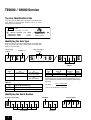
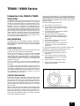
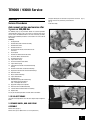
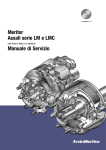
Meritor
Axle & Brake Service Manual
TE Series Axle
TE9000 / 93000 Service
INDEX
Section
Description
Page
THE MERITOR WARRANTY
3
THE AXLE IDENTIFICATION PLATE
Identifying the Axle Type, Identifying the Serial Number
4
INTRODUCTION TO THE TE9000 AND TE9300 SERIES AXLES
5
AXLE INSTALLATION
Limitations of Use, Stresses and Welding
5
MAINTENANCE SCHEDULE
Torque Recommendations, Recommended Lubricants
6
1
SERVICE PROCEDURES
AXLE ANNUAL SERVICE AND SERVICE AFTER 3 YEARS OR 300,000 KM
De-adjust Brake, Remove Wheel, Hub and Drum Assembly, Remove Brake Shoes,
Remove Anchor Pins, Clean Anchor Pin Bushes, Anchor Bracket and Cam Head,
Clean Spindle, Remove Cam Rollers from Brake Shoes, Clean Cam Rollers and Anchor Pins,
Assemble Anchor Pins, Inspect Brake Linings, Clean and Assemble Brake Shoes,
Inspect Brake Springs, Inspection of Camshafts and Camshaft Bearings for Play,
Removal of Camshafts and Camshaft Bearings,, Replacement of the Camshafts and
Camshaft Bearings, Refit Brake Shoes, Grease Camshaft Bearings, Inspect Brake Drums,
Remove Oil Seal, Wheel Bearing Inspection and Greasing, Routine Annual Hub Service,
3 Year/300,000 km Major Hub Service, Apply Anti-fretting Paste to Spindle,
Refit Hub, Drum and Wheel Assembly, Lubricate Brake Chamber Clevis Pin Assembly,
Adjust Brakes
7
2
ADDITIONAL PROCEDURES
AFTER 3 YEARS OR 300,000 KM
Removal and Refitting of Wheel Bolts, Fitting of the Pole Wheel, Fitting of the Sensor,
Sensor Output, Removal and Refitting of Dust Covers, Fitting of a Hubodometer,
Removal and Refitting of Brake Drum, Removal and Fitting of Antilock Equipment
16
2
TE9000 / 93000 Service
MERITOR HVS Limited Warranty
Warranty Procedure
1. AXLES, MECHANICAL AND FLEXAIR SUSPENSIONS,
INDAIR, OTHER MERITOR ACCESSORY PRODUCTS
Should any MERITOR equipment fitted to your trailer become
unserviceable within the warranty period, contact the trailer
manufacturer or MERITOR Service Department who will advise on the
appropriate action.
24 MONTHS PARTS AND LABOUR
Effective 1st March 1989
2. AXLES AND FLEXAIR UNITS ASSEMBLED BY
MERITOR HVS
36 MONTHS PARTS AND LABOUR
Effective 1st May 1992
The Company warrants that at its option it will repair or replace without
charge any original MERITOR axle, suspension, trailer component and
any axle and suspension assembly which is found on examination by the
Company to be defective as to material or workmanship.
A comprehensive network of original parts distributors and service
stations operate throughout Europe; this is supported internationally with
agents strategically placed around the world.
MERITOR HVS Ltd reserve the right to make changes in specifications
shown herein or add improvements at any time without notice or
obligation.
PARTS SHOWN ARE MADE FROM DRAWINGS IN WHICH COPYRIGHT
SUBSISTS. THE MAKING OF COPIES OF ANY OF THESE PARTS IS
PROHIBITED.
© MERITOR HVS LIMITED
Subject to: such assembly or component having been used solely on a
vehicle for which the specification and applications have been approved
by the Company’s engineering department and in accordance with the
approved applications and the vehicle not having been altered from the
manufacturer’s specification.
This warranty and the obligation to repair or exchange are complete and
exclusive. No liability is accepted for special or consequential
expenses/damages of any nature. The warranty does not apply to normal
wear and tear, abuse, damage caused by accident, failure to lubricate as
specified in accordance with manufacturer’s instructions, and, if
adequate storage facilities and protection are not provided, the damage
resulting from deterioration up to the time MERITOR products are
delivered to the first owner-user.
The high quality assurance management systems applied by MERITOR
are endorsed with the awarding of ISO 9001, Lloyd’s Register Quality
Assurance.
“MERITOR” is a registered trade mark of MERITOR HVS Ltd in Great
Britain, No. 1405496 in Class 12.
Allowances for labour will be paid for repair or replacement only as
determined and APPROVED by MERITOR Service Department BEFORE
SUCH LABOUR HAS STARTED.
All claims submitted under this warranty period must be filed in writing
with the MERITOR Aftermarket Services Division within 60 days from the
date of failure and all components involved in the claim must be retained
and available for inspection for 90 days from the date of claim being
submitted.
No deductions shall be made from remittances or current accounts in
respect of any warranty claims whilst those claims are being processed.
All claims must quote component Serial Numbers (where applicable) and
relevant vehicle number identification and also assembly Serial Number
and manufacturing date code where applicable.
This warranty is in substitution for and excludes all express or implied
statutory or other conditions, warranties, guarantees, or liabilities
(whether as to fitness for a particular purpose, quality, standard of
workmanship or otherwise). Save as provided herein the Company
accepts no liability whatsoever for defects in parts or for any injury, loss
or damage attributable thereto, howsoever arising (whether direct,
indirect or consequential).
3
TE9000 / 93000 Service
The Axle Identification Plate
Every axle leaving the ROR factory is fitted with an identification plate
which contains all the information needed to ensure the correct
replacement parts are obtained.
AXLE
APPROVAL No
TYPE
P41A BS15STVZO
B999999 G94 0000
9300Kg
V MAX
9300Kg
105KM/H
SERIAL No.
NOM CAPACITY
COMB CAPACITY
WREXHAM LL12 0PB UK
ASSEMBLED IN THE EEC
Identifying the Axle Type
All TE series axles are fitted with 10 stud, ISO 4107 spigot mount wheel
fixings and asbestos free Ø 420 x 180mm brakes as standard. Other
options are as shown below.
Anti-Lock Type
(Table A)
Axle series loading
(Table C)
Steer Axle = S
TE
S
10
E
Q
Type of wheel bolts
(Table B)
Table ‘A’
Table ‘C’
Axle Letter
Code
Exciter Ring
Type
Suitable
For
Axle
Series
Nominal Highway
Rating, Kg
Wall
Thickness
Max
Offset*
A
60t Pressed Steel
Grau MGX2 & MGX2E
Bendix MD2 & MD2A
90
9300
13mm
460mm
**93**
9300
16mm
490mm
W
100t Solid Ring
Wabco
Bosch
Grau DGX & MGX100
Table ‘B’
Axle Letter
Code
The axle ratings shown are for normal highway applications and any
special application for installation must be approved by Meritor Design
Engineering.
* NB: Offset =
ISO 4107 Wheel Mounting Type
MX
M22 x 1.5p wheel studs for single steel wheels
MXA
M22 x 1.5p wheel studs for single alloy wheels
Track – spring centres
2
** For use with non Meritor air suspensions
Identifying the Serial Number
Build Month
Non Asbestos Brake Lining
Sequential Number
B
Order Number
4
Build Year
TE9000 / 93000 Service
Introduction to the TE9000 & TE9300
Series Axles
The TE9000 & TE9300 series axles are manufactured to the same high
standards as the well established TM series axles. In fact, much of the
materials and manufacturing processes are common to both axle series.
The TE series axle has been designed with low weight and low cost of
ownership in mind, and is intended for use in predominantly tri-axle
applications, running on super single tyres at combined bogie weights up
to 27 tonne. Among many new features incorporated in the TE series axle,
two in particular stand out as conferring valuable benefits in service.
Firstly, the axles are manufactured with pre-set bearing clearances and
require no adjustment. The correct running clearances are obtained by the
careful control of manufacturing tolerances and matched bearings.
Secondly, the brake drum is outboard mounted and a full brake service
can be performed without removing the hub.
Axle Installation
The following notes and recommendations are offered as a guide to the
trailer manufacturer and service engineer. They are based on experience
gained from both the manufacture and servicing of single and multiple
axle installations.
LIMITATIONS OF USE
The following limitations apply to the TE series axles fitted with super
single tyres and used in tandem or tri-axle arrangements.
For normal road and RO–RO use at 9 tonne axle weight the TE9000
(13mm wall) beam is authorised for Meritor air and mechanical
suspensions only when assembled by Meritor. In all other instances of
normal road, RO–RO, and unrestricted tipper use at 9 tonne axle weight
using non-Meritor suspensions, air or mechanical, the TE9300 (16mm
wall) beam must be used.
For extreme conditions, i.e. narrow frame centres (<1100mm), high
centre of gravity (>2000mm) please consult Meritor Applications
Engineering.
In cases where suspensions of non-Meritor manufacture are used, the
trailer builder or suspension manufacturer must satisfy themselves as to
the suitability and compatibility of the axle and suspension, particularly
from a durability standpoint. Meritor will be pleased to assist in assessing
such compatibility, but cannot warrant the fitment of its axles to
suspensions of unknown characteristics.
During use the axle beam is subjected to a wide variety of forces. These
are caused by the payload, bumps in the road surface, cornering and
braking. Because these forces are constantly varying, the stresses in the
axle beam also vary, causing fatigue. The top and bottom of the beam
generally experience the greatest stresses and hence the most fatigue,
whilst the section of beam around the horizontal centre line sees the least
stress and fatigue.
Welds in the high stress areas will adversely affect the fatigue strength,
for this reason do not weld in the area 95mm wide top and bottom of the
beam, or 50° either side of the vertical centre line, as shown in the
diagram below. Weld tacks or weld spatter are not allowed in this area.
The effects of welding will be minimised if:
(a) all tack welds are at least 25mm long.
(b) the number of tack welds is kept to a minimum. If
possible clamp the bracket tightly to the beam and
eliminate the tack welds.
(c) the welding procedure recommended in the Meritor
suspension manual is followed.
(d) more than one weld run is required make the
following run with a different start/finish point and
before the previous run has cooled down. Descale
between runs.
(e) oil, rust and thick deposits of paint are removed
from the surfaces to be joined.
(f)
the welding consumables meet the relevant British
Standards and are used as recommended by the
manufacturer.
(g) at the end of fillet welds, the weld is ‘backed up’ to fill the crater.
The following precautions will prevent damage to the axle and
suspension during welding and improve service life:
(a) prevent weld spatter from falling on the axle and
road springs.
(b) ensure the earth connection is made to the axle
beam, preventing the passage of current through
the wheel bearings.
(c) do not test the arc on the axle beam or springs.
(d) remove scale and slag from fillet welds before
painting to prevent corrosion.
DO NOT WELD IN THIS AREA TOP AND BOTTOM
95
(50
°)
WELD IN THIS AREA
BOTH SIDES
STRESSES AND WELDING
The direction of welding should be as near the horizontal as possible and
welding around the corners of brackets or spring seats should be avoided.
Separate drawings exist on request from the Meritor Technical Sales
Department detailing seat welding procedures for both air and mechanical
Meritor suspensions.
WELD DETAILS: GENERAL REQUIREMENTS FOR AXLE BEAM
The beam material is controlled to ensure that pre-heating is normally not
necessary when welding as per BS5135.
5
TE9000 / 93000 Service
Maintenance Schedule
For suspension service intervals and maintenance procedures refer to
the relevant suspension manual.
Specific service intervals must be determined by each fleet operator
according to duty and experience. However, the following are minimum
requirements.
BEFORE ENTERING SERVICE
Check brake adjustment.
Torque check all wheel nuts.
160 km
Torque check all wheel nuts.
1600 km
Torque check all wheel nuts.
3 MONTHLY
Torque check all wheel nuts.
Check brake adjustment.
Check hub oil level. (Oil filled axles only).
Lubricate camshaft spherical bearings.
ANNUALLY
In addition to the 3 monthly inspection, a major brake overhaul is
advised along with a hub/bearing assembly grease examination as
described in SECTION 1.
BIENNIALLY OR 300,000 km
In addition to the annual inspection a hub/bearing assembly grease
change is required with careful examination of the bearings and
journals also described in SECTION 1.
TORQUE RECOMMENDATIONS
Hub cap bolts (grease and oil) . . . . . . . . . . . . . . . . . . . . 11/15 Nm
Dust cover bolts . . . . . . . . . . . . . . . . . . . . . . . . . . . . . . 50/60 Nm
Spherical bearing bolts (spline end) . . . . . . . . . . . . . . . . 50/60 Nm
Spherical bearing bolts (cam head end) . . . . . . . . . . . . . 50/60 Nm
Sensor fixing bolts (GRAU) . . . . . . . . . . . . . . . . . . . . . . . 8/11 Nm
Sensor fixing bolts (WABCO) . . . . . . . . . . . . . . . . . . . . . 25/30 Nm
Axle end nut . . . . . . . . . . . . . . . . . . . . . . . . . . . . . . 150/175 Nm
Brake drum retaining bolts . . . . . . . . . . . . . . . . . . . . . . 50/60 Nm
Wheelnut ISO M22 x 1.5 (steel and alloy wheels) . . . . 680/750 Nm
RECOMMENDED LUBRICANTS
Hub Bearings:
Total Multis EP2
Shell Calithia EP2T
Texaco Multifak EP2
BP LS EP2
Silkolene G62
Eurol Universalfett EP2
Elf Lithium EP2
Shell Alvania Grease EP(LF)2
Castrol Spheerol EPL2
Mobil Mobilux EP2
Fina Marson EPL2
SKF LGEP2
GB Lithium EP2
Brake components and camshaft bearings:
Total Extemp
6
HUB & BEARING GREASE FILL VOLUMES
Hub Cavity Fill . . . . . . . . . . . . . . . . . . . . . . . . . . . . . 325-375 gm
Inner Bearing Fill . . . . . . . . . . . . . . . . . . . . . . . . . . . . . 40-45 gm
Outer Bearing Fill . . . . . . . . . . . . . . . . . . . . . . . . . . . . . 32-37 gm
Hub Cap Fill . . . . . . . . . . . . . . . . . . . . . . . . . . . . . . . . . . . . . . Nil
TE9000 / 93000 Service
SECTION 1
Service Procedures
Straighten locking tab on tab washer using hammer and chisel (fig. 2).
Remove axle end nut (55mm A/F), and tab washer
(fig. 3).
Install wheel dolly.
Axle annual service and service after
3 years or 300,000 Km
The following step by step instruction details the essential operations
required for these services. The 3 year service is in effect the same as the
annual service with additional work on the hub and bearing assembly.
Details of these additional procedures can be found in the next section of
this manual.
Summary:
1.
2.
3.
4.
5.
6.
7.
8.
9.
10.
11.
12.
13.
14.
15.
16.
17.
18.
19.
20.
21.
22.
23.
24.
De-adjust Brake
Remove Wheel, Hub and Drum Assembly
Remove Brake Shoes
Remove Anchor Pins
Clean Anchor Pin Bushes, Anchor Bracket and
Cam Head
Clean Spindle
Remove Cam Rollers from Brake Shoes
Clean Cam Rollers and Anchor Pins
Assemble Anchor Pins
Inspect Brake Linings
Clean and Assemble Brake Shoes
Inspect Brake Springs
Inspection of Camshafts and Camshaft Bearings
for Play
Removal of Camshafts and Camshaft Bearings
Replacement of Camshafts and Camshaft Bearings
Refit Brake Shoes
Grease Camshaft Bearings
Inspect Brake Drums
Remove Oil Seal
Wheel Bearing Inspection and Greasing
20a. Routine Annual Hub Service
20b. 3 Year Major Hub Service
Apply Anti-fretting Paste to Spindle
Refit Hub, Drum and Wheel Assembly
Lubricate Brake Chamber Clevis Pin Assembly
Adjust Brakes
FIG. 1
FIG. 2
To carry out the above procedures in detail continue as follows:
1. DE-ADJUST BRAKE
Using the manual adjustment nut on the slack adjuster fully de-adjust the
brake.
2. REMOVE WHEEL, HUB AND DRUM
ASSEMBLY
Remove hub cap (fig. 1).
FIG. 3
Remove hub cap seal. (Note: If this is an ‘O’ ring discard it.)
7
TE9000 / 93000 Service
Install hub puller (Meritor part no. 21221512) and dismount hub, drum
and wheel assembly (fig. 4).
Remove hub, drum and wheel assembly and plug the inner bearing bore
with a clean cloth.
FIG. 4
3. REMOVE BRAKE SHOES
IMPORTANT: If the brake linings do not need to be replaced, mark the
brake shoes before removing them to ensure that they will be
reassembled to the same brake in the same position.
Release retainer springs using screwdriver or similar tool (fig. 5).
FIG. 6
4. REMOVE ANCHOR PINS
Remove anchor pins from anchor bracket (fig. 7).
FIG. 5
Free lower brake shoe from anchor pins, lower this end of brake shoe and
bring up to side of brake (fig. 6).
Free top brake shoe from anchor pins and lift both brake shoes connected
by the brake return spring off the anchor bracket.
FIG. 7
This should normally be possible without the use of tools, however, on
occasion after an excessively long period between services these
components may be seized, in this case use a suitable drift and hammer
to knock them out.
Remove ‘O’ rings from anchor pins.
8
TE9000 / 93000 Service
5. CLEAN ANCHOR PIN BUSHES, ANCHOR
BRACKET AND CAM HEAD
clips from the cam rollers and inspect for damage to the retaining tabs, if
they have cracked, broken off or failed to spring out the clip it must be
replaced.
Using a wire brush, clean each side of the anchor bracket in the area of
anchor pins, clean the bore of the anchor pin bushes, if necessary using
emery cloth.
8. CLEAN CAM ROLLERS AND ANCHOR PINS
Apply a small amount of grease to the bores of the anchor pin bushes and
smear a thin coating of grease on both sides of the anchor bracket around
the anchor pin bushes.
The working surfaces of the cam rollers and the anchor pins should be
cleaned to remove any build up of compressed debris adhered to the
working surfaces. In our experience the quickest and easiest way to do
this is to use the wire wheel fitted to one end of a pedestal grinder,
available in most workshops.
If the axle is fitted with anti-lock sensors, clean exposed sensor with a
cloth and push sensor from rear until it protrudes fully forwards.
9. ASSEMBLE ANCHOR PINS
6. CLEAN SPINDLE
Assemble one ‘O’ ring to anchor pin and apply grease to anchor pin, install
in the anchor bush from the rear pushing pin through sufficiently to fit the
second ‘O’ ring, then push back to central position. Repeat for other
anchor pin.
Clean working surfaces of cam head using strip of coarse emery cloth.
Check the spindle for damage and remove any fretting/rust on the bearing
journals with medium emery cloth strip.
Clean down the oil seal mounting wiping brake dust and rust away from
the area immediately behind the seal journal.
10. INSPECT BRAKE LININGS
Check the oil seal mounting for damage.
Do not disturb the brake lining surface if this shows a normal working
surface.
Check the spindle thread for damage by fitting the end nut by hand.
Provided thread damage is not severe it can be repaired using a 2mm
pitch thread file or M36 x 2 die nut (Meritor part no. 21224408). (Note:
The thread is not accessible for repair once the hub is mounted.)
Take care not to contaminate the surface of the brake linings with grease
etc.
7. REMOVE CAM ROLLERS FROM BRAKE
SHOES
If carrying out the service in winter months and the brake linings are
soaked with water it may be necessary to dry these by careful application
of heat to evaporate the water.
It is preferable to always renew the cam roller retainer clips when the cam
rollers are removed from the brake shoes.
Brake lining surface may be carefully linished by hand using coarse emery
cloth if contaminated by dirt, mud etc., but do not use any form of power
tool.
If new cam roller retainer clips are to be used simply prise rollers out of
shoes using a strong screwdriver, remove the clips from the cam rollers
and discard them (fig. 8).
Clean out compressed debris from rivet holes with screwdriver to avoid
possibility of damage to brake drum.
11. CLEAN AND ASSEMBLE BRAKE SHOES
Clean any corrosion from both anchor pin and cam roller pivot areas on
brake shoes using emery cloth and a screwdriver.
Apply specified grease to pivots areas on the brake shoes.
Apply specified grease to cam rollers, reassemble cam clips onto rollers
and refit cam rollers into shoes making sure retainer tabs locate in the
holes in the brake shoe gussets. Wipe excess grease from surface of cam
roller that contacts the cam head and make sure cam roller is free to
rotate in the brake shoe.
12. INSPECT BRAKE SPRINGS
Check the brake springs for damage, any spring showing signs of coil
separation should be replaced.
FIG. 8
However, with care it is possible to reuse the cam roller retainer clips,
insert a screwdriver into the hole in brake gusset and carefully press the
retaining tab of the cam clip whilst gently pulling the roller, keeping the
pressure on the cam roller turn the brake shoe over and repeat on the
other side, the cam roller and clip will pull out from shoe. Remove the
9
TE9000 / 93000 Service
13. INSPECTION OF CAMSHAFTS AND
CAMSHAFT BEARINGS FOR PLAY
Place a lever between the camshaft and axle beam close to the cam head
bearing and lever up and down to detect free play (fig. 9). This should not
be more than ±0.5mm at the bush (the amount at the lever will depend
on the lever length so discretion and judgement is required).
The camshaft can be removed along with the bearings with the hub
assembly in place using the key hole slot in the anchor bracket to allow
the cam head to pass through it. To proceed in this manner, unfasten the
M10 retaining screws securing the head and spline end bearings to the
brackets (figs 11 and 12). Guiding the head pull the cam head backwards
through the slot and pull the camshaft and bearings away from the axle
(fig. 13).
Unfasten the tie wraps securing the rubber boots.
Slide the spline end bearing and rubber boots off the camshaft and tap the
head end bearing along the body of the camshaft. Note it can be difficult
to remove the cam head bearing over the paint on the camshaft so some
paint may need to be removed using a wire brush.
An alternative method of removal when the hub assembly is not fitted is
to tap the camshaft through the bearings, first releasing the tie wraps
securing the rubber boots, striking the spline end hard with a soft mallet
initially to release the spring clip (fig. 10). The camshaft can then be fully
removed from the axle by pulling outwards. Once the camshaft is
removed the bearings can be removed from the axle by unfastening the 4
x M10 screws (figs 11 and 12) from each bearing.
FIG. 10
FIG. 9
Similarly place the lever between the axle and cam shaft close to the
spline end bearing and lever up and down checking for similar play as the
cam head bearing.
If the play is excessive this suggests wear is present in the bearings or the
camshaft journals and both should be replaced as necessary.
14. REMOVAL OF CAMSHAFTS AND CAMSHAFT
BEARINGS
Remove the clevis pin connecting the slack adjuster to the brake chamber
and rotate the slack adjuster out of the clevis by turning the adjusting nut.
Unfasten the circlip locating the slack adjuster. Slide the packing
washers, rubber boot and slack adjuster off the camshaft.
FIG. 11
10
TE9000 / 93000 Service
If the hub has been removed from the axle, clean any debris from the
locating faces on the anchor and cam brackets and fasten both bearings
in place with the M10 screws. Do not fully tighten at this stage. Pass the
camshaft through the head bearing and slide the rubber boots onto the
camshaft. Push the spline end through the spline end bearing. A hard tap
on the cam head end will be required to locate the spring clip into the
camshaft groove.
With the camshaft in position but both bearings not fully tightened, refit
the rubber boot slack adjuster packing washers and retaining washer
securing with the circlip. DO NOT TIGHTEN BEARING SECURING SCREWS
UNTIL BRAKE SHOES ARE FITTED.
16. REFIT BRAKE SHOES
If the old linings are to be reused, ensure each shoe is returned to its
original position as marked prior to removal.
FIG. 12
Either stand both brake shoes on their sides with the cam rollers together
and fit the return spring between the roll pins of both brake shoes.
Lift the top brake shoe, the lower shoe will automatically be picked up
also.
Place the cam roller of the top shoe in the dwell of the cam head and
locate the “D” slots onto the shoulders of the top anchor pin.
Or fit return spring to the roll pin of the top shoe and position the cam
roller of the top shoe onto the dwell of the cam head and the “D” slots
onto the shoulders of the top anchor pin. Lift the bottom shoe and connect
the free end of the return spring to the roll pin.
Then tip the lower brake shoe until the cam roller locates in the lower
dwell of the cam head, twist the brake shoe towards its fitted position
making sure that the cam roller locates in the dwell of the cam, and locate
the “D” slots onto the shoulders of the lower anchor pin. Refit retainer
springs, a suitable tool can be made by slotting the blade of a screwdriver.
FIG. 13
15. REPLACEMENT OF THE CAMSHAFTS AND
CAMSHAFT BEARINGS
If the camshaft was removed with the hub in place proceed as follows:
Apply a coating of grease onto the cam head journal and slide the cam
head bearing onto the camshaft and up to the cam head until the spring
clip is ready to snap into position (resistance will be felt).
Ensure brake shoes are sitting correctly on cam head, if necessary correct
by aligning the brake shoes at cam roller end.
During the above assembly it is important not to contaminate the surface
of the brake linings with grease, remove any slight contamination by
wiping with clean absorbent paper.
With the shoes fitted apply the brake by pulling on the slack adjuster
several times then in the off position tighten the cam and spline cam
bearing securing screws to the specified torque.
Slide the inner rubber boots and the spline end bearing onto the camshaft.
Clean any debris off the locating faces on the anchor and cam brackets
and apply a coating of grease onto the spline end camshaft journal.
Position the cam head through the anchor bracket key hole slot and slide
the spline end bearing through the cam bracket slot. Fasten the bushes in
position using the original M10 screws. If there is any sign of thread
damage or rust replace the screws with new ones. Do not fully tighten
them at this stage.
11
TE9000 / 93000 Service
17. GREASE CAMSHAFT BEARINGS
Grease camshaft bearings using grease gun (fig. 14), it is possible to see
the grease extrude from the side plates of the camshaft head bearings
with the hub and drum removed. Ensure the correct specification of
grease is used.
If the oil seal has remained on the spindle journal lever it off taking great
care not to damage the spindle. Clean the area around the oil seal journal
as detailed in paragraph 6. Discard the oil seal.
Never reuse an oil seal after the hub has been dismounted from the
spindle.
20. WHEEL BEARING INSPECTION AND
GREASING
Step 20a describes the routine inspection and service.
Step 20b should be carried out every 300,000 km, or every 3 years or if
the grease appears dirty, contaminated or burnt, or if no cavity fill is
present.
Refer to grease type and fill volumes specified on page 6.
20a. ROUTINE ANNUAL HUB SERVICE
INNER BEARING:
FIG. 14
If the grease within the hub is clean and does not appear or smell burnt
there should be no requirement to totally clean down the assembly and
re-grease the bearings.
Care must be taken not to contaminate the lubricant during the inspection.
18. INSPECT BRAKE DRUMS
Clean excess brake dust from brake drum and inspect brake drum bore
for surface corrosion, damage and excessive wear.
Remove light corrosion by using coarse emery cloth at an angle of 45
degrees in one direction and then 45 degrees in the other direction to
produce a cross hatch effect, do not use any form of power tool.
Check the hub cavity and inner bearing for contamination caused when
the hub was dismounted from the spindle. Contamination must be
removed and if necessary a total clean down and re-lubrication as
described in step 20b must be performed.
Remove the inner bearing cone (fig. 16) and check the condition of the
grease.
If the drum bore shows signs of heat crazing it usually can be reused but
if the heat crazing is severe the drum should be replaced.
It is permissible to machine out the brake drum to a maximum of
Ø423mm. Oversize cam rollers must be fitted if this is done (21006610A).
19. REMOVE OIL SEAL
If the oil seal is still within the hub remove it with a work shop pri-bar and
discard it (fig. 15). Take care not to contaminate the inner bearing and hub
cavity.
FIG. 15
12
FIG. 16
TE9000 / 93000 Service
Inspect the rollers, bearing cage and raceway for damage and debris.
Re-grease the inner bearing to supplement the grease lost during the
removal of the oil seal. Be certain to work the grease deep into the cage
and rollers.
Check the raceway for any damage before the inner bearing cone is
replaced.
Press the inner bearing fully home into the cup as this helps the location
of the oil seal driver.
Fit the oil seal onto the driver (Meritor Part No. 21221510), note that the
oil seal cannot be fitted successfully without the correct driving tool.
Make sure the ‘oil side’ is facing away from the face of the driver
with the outer face of the seal fully seated. Failure to seat the seal in
this way can cause the seal to be fitted skew.
Locate the nose of the driver into the inner bearing cone and drive the seal
home (fig. 18). Check that the outer most rubber edge of the seal is
flush with the face of the hub all round.
OUTER BEARING:
Remove the retaining clip, washer and outer bearing cone (fig. 17). Similar
to the inner bearing, check the condition replacing any grease lost by
working grease deep into the bearings rollers and cage.
Check the raceway for damage and the hub cavity fill before replacing the
outer bearing.
Fit the retaining washer and clip to hold the cone in place ready for remounting the hub.
FIG. 18
Look carefully for:Cage damage
Corrosion on the raceways/rollers
Metallic debris
Pitting
Metallic flakes
Damage to rollers/raceways
Bearings must be replaced if there are any of the above defects. Small
defects will propagate and lead to bearing failure.
FIG. 17
20B. 3 YEAR/300,000 KM MAJOR HUB SERVICE
Remove the retaining clip, washer, inner and outer bearing cones (figs 17
and 18) and clean off all grease to inspect the bearings. Do not use water,
steam or air jets to clean the bearings.
Wipe clean the hub cavity removing all the old grease and any debris. All
surfaces must be totally clean.
If there are any discoloured bands on the rollers and raceways inspect the
bearing very carefully. It can be an indication of some of the defects
described above. Treat with extreme caution if the grease smells burnt.
If there is any doubt about the condition of a bearing discard and fit a new
one.
Always replace cup and cone together.
ALWAYS USE GENUINE ROR BEARINGS – STANDARD ISO BEARINGS
CANNOT BE USED.
Check the bearing cups are hand tight within the hub bores. If a cup is
loose the hub must be replaced.
Following a complete hub and bearing clean down use a 400ml tube of
Meritor Hub Grease Blue Lithium EP2 which is sufficient to re-lubricate
both the inner and outer bearings and the hub cavity.
13
TE9000 / 93000 Service
Dry the bearings of any solvent used for cleaning the bearings.
Thoroughly re-pack the inner and outer bearings with grease. Work the
grease deep into the rollers with your hands until the cages are solid
packed with grease. Always place greased bearings in a clean area
and protect from falling debris.
Press the inner bearing fully home into the cup. (This helps the location of
the oil seal driver.)
Fit the oil seal onto the driver (Meritor Part No. 21221510), note that the
oil seal cannot be fitted successfully without the correct driving tool.
Make sure the ‘oil side’ (written on the rubber) is facing away from
the face of the driver, with the outer face of the seal fully seated on
the face of the driver. Failure to seat the seal in this way can cause the
seal to be fitted skew.
Locate the nose of the driver into the inner bearing cone and drive the seal
home (fig. 18). Check that the outer most rubber edge of the seal is
flush with the face of the hub all round.
Replace the greased outer bearing.
Fit the retaining washer and clip to hold the cone in place until you are
ready to remount the hub.
Fill the empty cavity of the hub with the grease left in the 400ml tube. Do
not over fill with extra lubricant.
21. APPLY ANTI-FRETTING PASTE TO SPINDLE
Apply ‘Optimol White Paste T’ to both the inner and outer bearing journals,
approximately 1-2ml per journal. Smear the paste evenly over the bearing
areas and up the inner bearing abutment shoulder (fig. 19).
This paste will reduce wear and ease the removal of the bearing cones
during future maintenance.
22. REFIT HUB, DRUM AND WHEEL ASSEMBLY
Using a wheel dolly align hub, drum and wheel assembly with the axle
spindle, adjust position and height until brake drum fits over brake linings.
If the outer bearing is removed be certain to place it in a clean area before
it is reassembled in the hub.
To mount the hub assembly without the outer bearing, retaining washer
and clip in place, push assembly fully onto axle and guard against striking
the oil seal on the spindle end, replace the oil seal if any damage occurs.
Fit the outer bearing cone. Fit the outer bearing retaining washer with the
writing outer most and fit retainer clip.
If the outer bearing is still in place check alignment and height and align
key on retainer washer with key way on spindle end, gently push the
assembly fully onto the axle, guard against striking the oil seal on the
spindle end, replace the oil seal if any damage occurs.
Carefully examine the tabs and keyway locater for signs of wear or
damage, if any doubt exists use a new tab washer. Fit tab washer locating
in key way on spindle end, fit axle end nut hand tight and remove wheel
dolly.
14
FIG. 19
Torque axle end nut to 150/175 Nm. Whilst tightening axle end nut rotate
wheel several times to seat wheel bearings (fig. 3).
Never torque the final stages of the end nut without rotating the hub.
Failure to do this can cause bearing damage and result in the hub
not seating properly.
Bend tab washer tab closest to a full flat on the end nut using a suitable
tool (Meritor Part No. 21221514).
Check the hub cap mounting face and gasket groove is free of debris and
damage, wipe clean the mounting faces.
Fit hub cap gasket (Meritor Part No. 21223797) to the hub cap with the
flat face of the seal against the cap. A ‘smear’ of grease within the
external hub cavity and on the back of the hub cap is good practise to
prevent corrosion in the event of any moisture ingress.
Fit hub cap and gasket to hub, tighten hub cap screws sequentially
observing the compression of the gasket around the fixings, finally torque
hub cap screws to 11/15 Nm (fig. 1). Over tightening will split the gasket.
Too little pressure on the gasket may not provide an effective seal.
TE9000 / 93000 Service
23. LUBRICATE BRAKE CHAMBER CLEVIS PIN
ASSEMBLY
Lubricate the clevis pin assembly from both sides with oil, and make sure
the brake can be operated easily by pulling the slack adjuster by hand.
24. ADJUST BRAKES
MANUAL SLACK ADJUSTERS:
Using the manual adjustment nut on the slack adjuster adjust the brake
until the wheel can not be turned by hand. Back off brake until it is just
possible to freely turn the wheel without resistance from the brake linings.
AUTOMATIC SLACK ADJUSTERS:
Follow the appropriate setting procedure for the type of automatic slack
adjuster fitted. Instructions are available through Meritor Technical Sales
Department.
15
TE9000 / 93000 Service
SECTION 2
Additional Procedures
After 3 years or 300,000 km
REMOVAL AND REFITTING OF WHEEL BOLTS
With the hub removed from the axle, support it by placing blocks under
the wheel flange. Using the wheel bolt removal tool (21205455) drive out
the wheel bolts (fig. 20).
FIG. 21
FITTING OF THE POLE WHEEL
FIG. 20
To replace wheel bolts, turn the hub over, oil seal end upwards, and
support the hub on the brake drum aligning the holes in both hub and
drum. Using the wheel bolt driving tool (21211274) drive the bolts home
in turn (fig. 21).
16
With the hub removed from the axle, place it, oil seal end upwards, on a
clean, flat surface and cover the bore with a clean cloth to protect the
bearings and grease from contamination. Check that the pole wheel
mounting spigot on the hub is clean and free from rust using medium
emery paper to clean up if necessary. Ensure no emery dust or other
debris contaminates the bearings or grease.
The pole wheel (21221064) can be fitted hot or cold using the seal driving
tool (21221510). If fitting hot, heat the pole wheel evenly to a maximum
of 150°C using a hot plate or induction heater and place onto the hub
spigot ensuring it fully seats. If fitting cold, use the oil seal driving tool to
drive the pole wheel onto the hub spigot ensuring it bottoms out against
the mounting shoulder (fig. 22).
TE9000 / 93000 Service
The mounting block is fixed to the beam using a screw (21221521)
tightened to 25/35 Nm. During tightening of the screw move the block
from side to side so that it is correctly seated and is within ±2.5° to the
wheel axis. The sensor assembly may be rotated in the mounting block to
allow the cable to pass either side of the anchor bracket. Pass the sensor
cable through the dust cover using the uppermost hole and fit grommet
(21220842).
SENSOR OUTPUT
Connect the output cable to a suitable multimeter. Rotate the hub by hand
at a constant rate of approximately 30 rpm and note the maximum and
minimum readings. The minimum voltage reading should be 400
millivolts and the ratio of max/min should not exceed 2. If either values
are not obtained check the installed air gap between the sensor and pole
wheel does not exceed 0.7mm and the pole wheel runout does not exceed
0.2mm. If the installation is not correct contact the supplier of the antilock equipment for further advice.
REMOVAL AND REFITTING OF DUST COVERS
Normally most service operations can be carried out with dust covers in
place. If for any reason they must be replaced unfasten the 4 screws at
each wheel end securing the dust cover using an M13 socket (fig. 24) and
remove the two halves of each dust cover. When refitting ensure that the
halves are pushed together and locating tabs correctly engaged to ensure
any gaps are minimised before tightening the screws to 50/60 Nm.
FIG. 22
FITTING OF THE SENSOR
Assemble the spring bush (21213036) into the sensor mounting block
(22221063) (fig. 23). Lightly grease the sensor assembly and push fully
into the mounting block. When the hub is refitted the pole wheel will push
the sensor back and thus obtain the correct clearance.
FIG. 24
FITTING OF A HUBODOMETER
The TE axle may be fitted with an hubodometer by using either a special
hub cap or additional mounting strap. It is not possible to fit an
hubodometer to a standard hub cap and attempting to do so may cause
damage to the spindle or the sealing of the hub cavity.
For hubodometer types up to 85mm outside diameter, use special hub
cap (21221060).
FIG. 23
17
TE9000 / 93000 Service
The hubodometer is best assembled with the hub cap off the axle. Place
the hub cap on a clean, flat surface. Fit the nut to spanner (fig. 25) and
using a small amount of grease locate the washer on the nut.
REMOVAL AND REFITTING OF BRAKE DRUM
The brake drum can be separated from the hub after removal of the road
wheel as follows. Remove the two countersunk drum retaining screws
from the drum flange face using a 10mm Allen key (fig. 27).
FIG. 25
Position the nut and washer under the mounting hole using the spanner
and lower the hubodometer through the hole to engage the thread. Rotate
the hubodometer to screw the nut along the mounting stud until hand tight
then tighten with the spanner in the normal way. The hub cap and gasket
can then be refitted to the axle as described in section 22.
FIG. 27
These screws can then be used to jack the drum free of its locating
spigots by refitting them to the two plain tapped holes in the drum flange
ensuring they are tightened evenly to prevent the drum tipping (fig. 28).
For hubodometer types larger than 85mm outside diameter, use
hubodometer mounting plate 21222610.
Fit the hubodometer to the centre hole of the mounting plate. Remove
three of the five hub cap fixing screws from the hub end to suit the bracket
fixing bolt hole pattern. Offer the hubodometer bracket to the front face of
the standard hub cap and replace the three fixing screws as described in
section 22.
A range of hubodometers are available to suit various tyre sizes as shown
in fig. 26.
Tyre Size
15R22.5
F20 PILOTE
12.00 x 20
18 x 22.5
16.5 x 22.5
11.00 x 20
12.00 x 22.5
10.00 x 20
11.00 x 22.5
10.00 x 22.5
9.00 x 20
8.25 x 20
Part Number
Kilometres
Miles
21212648
21212649
21206207
The drum can then be lifted clear of the hub.
21204639
21021019
21021018
21023810
21021016
21022758
21021015
21023732
21021014
21021013
FIG. 26
18
FIG. 28
To refit the brake drum, locate it over the wheel studs ensuring it is
correctly orientated to align the two countersunk retaining bolt holes with
the tapped holes in the hub. Refit the two retaining screws and tighten to
50/60 Nm ensuring that the drum is fully seated on its locating spigot.
Ensure the retaining screw heads are below the surface of the brake drum
flange face after tightening.
TE9000 / 93000 Service
REMOVAL AND FITTING OF ANTILOCK
EQUIPMENT
All TE axles are provided with a means of fitting antilock equipment. Every
hub has a machined spigot to locate the pole wheel and axle beams are
plain drilled for self tapping bolt to allow the fitting of the sensor mounting
block (fig. 29). It is important that the correct bolt is used.
ITEM
A
B
C
D
E
DESCRIPTION
Pole Wheel
Sensor Bracket
Spring Bush
Screw & Spring Washer
Sensor Assembly
C
PART NO.
21221064
22221063
21213036
21221521
21213034
D
B
E
A
FIG. 29
19
Meritor HVS Limited
Commercial Vehicle Systems
Rackery Lane, Llay
Wrexham LL12 0PB
U.K.
Telephone: +44 (0)1978 852141
Fax: +44 (0)1978 856173
Meritor HVS (Mitry-Mory) S.A.
Commercial Vehicle Systems
Z.I. du Moulin à Vent
9 rue des Frères Lumière
77290 Mitry-Mory
France
Telephone: +33 (0)1 64.27.44.61
Fax: +33 (0)1 64.27.30.45
Meritor HVS (Verona) s.r.l.
Commercial Vehicle Systems
Via Monte Fiorino, 23
37057 San Giovanni Lupatoto
Verona
Italy
Telephone: +39 045 8750399
Fax: +39 045 8750640 / 8750513
Meritor HVS (Barcelona) S.A.
Commercial Vehicle Systems
Ctra. Granollers - Sabadell Km. 13,3
Poligono Argelagues
08185 Lliçà de Vall
Spain
Telephone: +34 (9)3 843 95 68
Fax: +34 (9)3 843 83 59
ArvinMeritor Inc.
World Headquarters
2135 West Maple Road
Troy, Michigan 48084
U.S.A.
Telephone: +1 248 435 1000
ArvinMeritor
Commercial Vehicle Aftermarket AG
Neugutstrasse 89
8600 Dübendorf
Switzerland
Telephone: +41 (0)1 824 8200
Fax: +41 (0)1 824 8264
ArvinMeritor
Commercial Vehicle Systems
Postbus 255
5700AG Helmond
Churchilllaan 204A
5705BK Helmond
Holland
Telephone: +31 (0)492 535805
Fax: +31 (0)492 547175
ArvinMeritor South Africa
Commercial Vehicle Systems
Telephone: +27 (0) 83 602 1603
For further information contact
Meritor HVS Limited
Commercial Vehicle Systems
Rackery Lane, Llay
Wrexham LL12 0PB
U.K.
Telephone: +44 (0)1978 852141
Fax: +44 (0)1978 856173
www.arvinmeritor.com
© Copyright 2001
Meritor Automotive
All rights Reserved
Publication 4.42.3
Descriptions and specifications were in
effect at the time of publication and are
subject to change without notice or
liability. Meritor reserve the right to make
design improvements, change or
discontinue parts at any time.