1
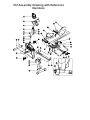
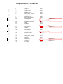
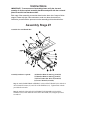
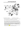
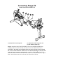
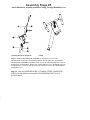
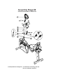
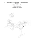
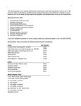
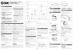
212 Schwinn® Recumbent Exercise Bike
Parts List
Full Size Hardware Chart
Product Illustration
Assembly Instructions
FITNESS SAFEGUARDS AND WARNINGS
Before starting any exercise program, consult with your physician or health
professional. He or she can help establish the correct exercise frequency,
intensity (target heart rate zone) and time appropriate for your particular age and
condition.
The following 3 warnings listed below are also located on the computer console
mast of the exercise bike. Failure to follow any of these safeguards may result in
injury or serious health problems.
•
•
•
Read and understand the Owner’s Manual and operation instructions prior
to use. If you do not have an Owner’s Manual, call 1-800-864-1270 to
obtain one.
If you feel any unusual pain or tightness in your chest, shortness of breath
or dizziness, feel faint or have any discomfort while you exercise, STOP!
Consult your physician.
Keep children and pets away.
Other Important Safeguards and Warnings
•
•
•
•
•
•
•
•
•
•
•
•
•
•
Do not exceed maximum user weight of 136 kg (300 lb.)
It is the responsibility of the owner to ensure that all users of this
equipment are adequately informed of all precautions.
Use this equipment only on a solid level surface. Cover the floor or carpet
beneath this equipment for protection.
Read the Warning Label located on the computer console mast.
Do not place fingers or any other objects into moving parts of the exercise
equipment.
This equipment is designed for use by persons aged 13 years and older.
Teenagers should be supervised.
Always wear athletic shoes for foot protection. Avoid wearing loose
clothing that may become entangled in the drive mechanism.
Warn bystanders to keep a safe distance, especially from the moving
pedals. Do not allow anyone to touch the bike while it is in operation.
This equipment is for home use only. Do not use in a commercial,
institutional, or rental setting.
Care should be taken when mounting or dismounting the exercise bicycle.
Do not operate in damp or wet conditions.
Follow proper set-up and guidance as outlined in the Owner’s Manual and
Assembly Instructions. Only use the bike as outlined in usage instructions
of the Owner’s Manual.
Prior to each use inspect the bike for loose, broken, or worn parts. Do not
use if found in this condition. The safety of the equipment can only be
ensured if it is regularly examined and maintained. (See Maintenance
section of the Owner’s Manual)
Refer to the Maintenance section in the Owner’s Manual and disconnect
power supply before servicing the bike.
•
•
Replace Warning Label if damaged, illegible, or removed.
We recommend that a minimum distance of 1 meter (39 inches)
surrounding the bike is kept clear of all obstructions, including children,
bystanders, and pets. This is to ensure adequate clearance for easy
access to the bike and to avoid any possible contact with the moving
pedals
212 Schwinn Recumbent Bike Parts List,
Hardware Chart, and Assembly Instructions
Assembly of the 212 Recumbent Bike is divided into 5 easy stages; each
comprised of only a few setup steps. Before proceeding with the assembly,
please read over the easy to follow instructions to familiarize yourself with the
process.
• A flat area of 5’ x 7’ is suggested to assemble and properly use the 212
exercise bike.
• You will need the following tools to complete the assembly:
5mm Allen wrench (supplied)
Open wrench 13mm, 14mm, 15mm (supplied)
Phillips screwdriver (supplied)
Also, to ensure quick and easy set up of the 212 Recumbent Bike, please verify
the size and quantity of each of the enclosed assembly hardware. Included is a
handy full size hardware chart and parts list of each of the required assembly
hardware. Simply match up the corresponding hardware to each full size
drawing.
Parts List
Check
__
__
__
__
__
__
__
__
__
__
__
__
__
__
__
__
__
__
__
__
__
__
__
__
__
__
__
__
__
Quantity
1
1
4
1
15
4
1
1
1
1
1
4
1
1pr
19
1
1
1
1
1
1
1
1
8
1
1
1pr
8
1
Description
Computer
Handlebars
Computer Screws
Handlebar Post
Allen Bolt 8x1.25x16L
Wavy Washer
Upper HR Wire
Upper Computer Wire
Lower Computer Wire
Lower HR Wire
Front Stabilizer
Flathead Screw 8x16L
Main Frame
Pedals
Flat Washer
Seat Rail Post
Rear Stabilizer
Seat Rail
Seat Rail HR Wire
Seat Handlebar
Seat Adjustment Knob
Small Flat Washer
Seat Bottom
Allen Bolt 8x1.25x45L
Seat Support Frame
Seat Back
Bottle Holder
Screw 5x14L
AC Adaptor
Reference #
1
2
3
4
5
6
7
8
9
10
11
12
13
14
15
16
17
18
19
20
21
22
23
25
26
27
28
29
72
Hardware Chart
Stage#1
Screws M8xP1.25x16mm
Stage#2
Allen Bolt M8xP1.25x16mm
Flat Washer
? 8*? 16*2T
Screws M5x14L
Stage#4
Stage#3
Flat Washer
? 8*? 16*2T
Screws M8xP1.25x
Stage#6
Screws M8xP1.25x16mm
Stage#5
Flat Washer
? 8*? 16*2T
mm
Screws M8xP1.25x
mm
Stage#10
Flat Washer
? 8*? 16*2T
Screws M8xP1.25x16mm
Flat Washer
? 8*? 16*2T
Stage#8
Screwdriver
Allen Key
Allen Bolt M8xP1.25x16mm
Note: Please verify you have all correct parts and quantities before assembling
unit.
If you are missing items, are short quantities, or have damaged components,
please contact Schwinn at 1.800.864.1270.
212 Assembly Drawing with Reference
Numbers
Replacement Parts List
Reference #
__
__
__
__
__
__
__
__
__
__
__
__
__
__
__
__
__
__
__
__
__
__
__
__
__
__
__
1
2
3
4
5
6
7
8
10
11
12
14
15
16
17
18
19
20
21
22
23
25
26
27
28
29
72
Description
Computer
Handlebars
Computer Screws
Handlebar Post
Allen Bolt 8x1.25x16L
Wavy Washer
Upper HR Wire
Upper Computer Wire
Lower HR Wire
Front Stabilizer
Flat head Screw 8x16L
Pedals
Flat Washer
Seat Rail Post
Rear Stabilizer
Seat Rail
Seat Rail HR Wire
Seat Handlebar
Seat Adjustment Knob
Small Flat Washer
Seat Bottom
Allen Bolt 8x1.25x45L
Seat Support Frame
Seat Back
Bottle Holder
Screw 5x14L
AC Adaptor
Part #
18143
18200
18094
18196
18001
18098
18086
18085
N/A
N/A
18136
18255
18101
18203
18126
18080
18082
18207
N/A
18225
18246
18072
18201
18247
18135
N/A
18007
Deleted: 18064
Deleted: 18189
Deleted: 18198
Deleted: 18191
Deleted: 18214
Deleted: 18250
Deleted: 18250
Instructions
IMPORTANT!: To ensure ease of assembly please verify the size and
quantity of all the required assembly hardware and parts with the enclosed
parts list and full size hardware chart.
Each step of the assembly process has been broken down into 6 easy-to-follow
stages. Please take just a few moments to read over these instructions to
familiarize yourself with the process to make assembly quick and trouble-free.
Assembly Stage #1
Assemble Seat and Handle Bar
Assembly hardware required:
(8) M8 Allen Bolts 45 mm long (item #25)
(4) M8 Allen Bolts 16 mm long (item #5)
(12) Flat Washer Ø8* Ø 16*2T(item #15)
(8) Screws M4x14L (item #29)
Step 1: Attach HANDLEBAR ASSEMBLY (#20) to SEAT FRAME (#26) with the 4
ALLEN BOLTS 16mm (#5) and 4 FLAT WASHERS (#15). Tighten bolts with the
provided Allen wrench.
Step 2: Attach the right and left WATER BOTTLE HOLDERS (#28) with the
SCREWS (#29) to the underside of the SEAT BOTTOM (#23) using the provided
screwdriver.
Step 3: Attach SEAT (#23) to SEAT FRAME (#26) with 4 ALLEN BOLTS 45mm
(#25) and 4 WASHERS (#15). Tighten Bolts.
Step 4: Attach SEAT BACK (#27) to SEAT FRAME (#26) with 4 ALLEN BOLTS
45mm (#25) and 4 WASHERS (#15). Tighten Bolts.
Note: Finished seat should look like picture below:
Assembly Stage #2
Attach Rear Stabilizer and Seat Rail to
Seat Assembly
Assembly hardware required:
(4) M8 Allen Bolts 16mm (item #5)
(4) Flat Washers Ø8 * Ø16 * 2T (item#15)
(2) Flat Head Screws (item #12)
Step 5: Attach the REAR STABILIZER (#17) to the SEAT RAIL POST (#16) with 2
FLAT HEAD SCREWS (#12). Tighten bolts.
Step 6: Attach SEAT RAIL (#18) to SEAT RAIL POST (#16) with 4 FLAT
WASHERS (#15) and 4 ALLEN BOLTS (#5). Tighten bolts
Step 7: Insert SEAT PIN ADJUSTMENT KNOB (#3) into SEAT FRAME (#8).
Slide the seat assembly from stage 1 onto the SEAT RAIL (#9). Tighten seat
assembly to the rail with the SEAT PIN ADJUSTMENT KNOB (#3). Insert HR
CABLE (#47) into HR input on the back of the seat assembly (inset picture).
Assembly Stage #3
Attach Front Stabilizer Tube and Pedals to Main Unit
Assembly Hardware Required:
(2) Flat Head Screws (item #12)
Step 8: Attach FRONT STABILIZER TUBE (#11) to the MAIN UNIT (#13) with 2
FLAT HEAD SCREWS (#12). Tighten Bolts with provided wrench.
Step 9: Attach RIGHT PEDAL (#14) to the right crank arm on the MAIN UNIT
(#31). Thread the pedal onto the crank arm and then tighten with pedal wrench.
Attach LEFT PEDAL (#14) to the left crank arm on the MAIN UNIT (#13). Thread
the pedal onto the crank arm and then tighten with pedal wrench. Note: There is a
right pedal and a left pedal, marked by R and L. The threading on the left pedal
is reversed from the right pedal. Counterclockwise rotation tightens while
Clockwise rotation loosens on the left pedal. To avoid stripping of the threads be
careful to use the proper pedal.
Attach PEDAL STRAPS (#18) to each PEDAL (#14). Again, each strap is labeled
with an R or an L corresponding to the right and left pedal straps.
Assembly Stage #4
Attach Seat Rail to Main Unit
Assembly Hardware Required:
(3) Allen Bolts 16 mm long (item #5)
(3) Flat Washers (item #15)
Step 10: Attach the SEAT RAIL HR WIRE (#19) to the LOWER HR WIRE (#10).
Carefully slide the seat rail assembly onto the receiver on the MAIN UNIT (#13).
CAUTION! Be careful not to pinch the heart rate wires between the seat rail and
the receiver on the main unit. Failure to do so could cause damage to the wires and
cause the heart rate feature not to function. Attach the SEAT RAIL to the MAIN
UNIT (#13) with 3 16mm ALLEN BOLTS (#5) and 3 FLAT WASHERS (#15). Tighten
bolts. Attach the heart rate wire to the rear port on the back of the seat.
Assembly Stage #5
Attach Handlebar Assembly and Run Cabling Through Handlebar Post
Assembly Hardware Required:
NONE
Step 11: Slide the HANDLEBAR ASSEMBLY (#2) into the receiver on the
HANDLEBAR POST (#4). Slide the threaded post into the slider tube and attach the
HANDLEBAR ASSEMBLY SLIDER TUBE (#2) and the HANDLEBAR POST (#4) by
threading the ADJUSTMENT KNOB (#21) and the SMALL FLAT WASHER (#22) into
the threaded post. Place the end cap on the end of the slider tube on the HANDLEBAR
ASSEMBLY (#2).
Step 12: Take the UPPER HR WIRE (#7) and the UPPER COMPUTER
WIRE (#8) and slide them through the HANDLEBAR POST (#4) as
pictured above.
Assembly Stage #6
Attach Console Mast to Main Unit
Assembly Hardware Required: (4) Allen Bolts 16 mm long (item #5)
(4) Curved Washers (item #6)
(4) Computer Screws (item #3)
Step 13: Before sliding the HANDLEBAR POST (#4) onto the MAIN UNIT (#13),
attach both HR CABLES (#7 & #10) as well as the COMPUTER CABLE (#8 & #9).
Slide the HANDLEBAR POST (#4) onto the MAIN UNIT (#13). Fasten with 4 BOLTS
(#22) and 4 CURVED WASHERS (#19). Tighten with provided Allen wrench.
Step 14: Attach UPPER COMPUTER CABLE (#7) and HR CABLE (#8) to under side
of COMPUTER (#1). Place COMPUTER (#1) on top of HANDLEBAR ASSEMBLY
(#2), the reading rack should wrap around the bottom of the COMPUTER (#1). Attach
COMPUTER (#1) to HANDLEBAR ASSEMBLY (#2) with COMPUTER MOUNTING
SCREWS (#3). (In computer back) Tighten with Phillips head screwdriver.
Step 15: Plug AC ADAPTOR (#71) into the wall and into the recumbent bike. The
POWER PLUG (#72) on the bike is located at the front end of the MAIN UNIT (#13)
just above the FRONT STABILIZER TUBE (#11)
Seat Adjustment
For best results, the seat should be adjusted for your height.
1. Unlock “seat locking” mechanism.
2. Adjust seat location so that with feet on the pedals, you can comfortably reach
pedal at full extension.
That’s it!
You’re finished and now you can begin to reach your fitness goals!
Please reference the Owner’s Manual for information regarding computer
operation, product maintenance, warranty information, and general fitness and
exercise guidelines.
Schwinn Customer Service
1.800.864.1270
Troubleshooting the Schwinn 212 Recumbent
Exercise Bike
TIP: Use assembly diagram(s) as reference when troubleshooting unit.
PROBLEM: Computer will not start, function, or is blank…
(SOLUTION):
1. Ensure the batteries the unit is plugged into a 110v outlet.
2. Check the wiring connections and connector orientation
made to the computer.
3. Confirm that wiring (cable assembly) has not been
damaged
4. If computer still fails to start please call 1.800.864.1270
for assistance.
PROBLEM: No Heart Rate on computer…
(SOLUTION):
1. Check the connections made at the computer and
handlebars
2. If heart rate still fails to work call 1.800.864.1270 for
assistance.
PROBLEM: Bike will not sit level…
(SOLUTION):
1. Adjust the levelers on the rear stabilizer.
Note: If you need additional support information or assistance in troubleshooting,
please contact us at: 1.800.864.1270