1
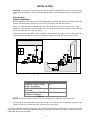
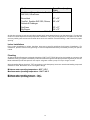
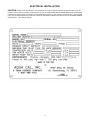
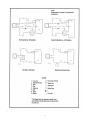
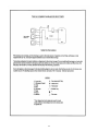
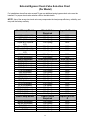
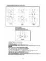
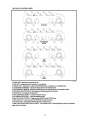
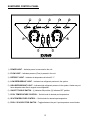
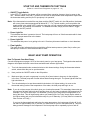
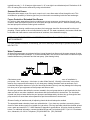
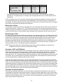
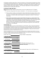
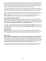
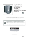
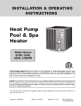
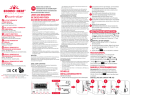
HEAT PUMP POOL & SPA HEATER
INSTALLATION
&
OPERATION
MANUAL
727-823-5642
AQUA CAL, INC.
2737 24TH STREET NORTH
ST. PETERSBURG, FL 33717
800-786-7751
FAX 727-821-7471
Index
Installation ................................................................................................................. 3
Unit Location.................................................................................................... 3
Plumbing.......................................................................................................... 4
Electrical.................................................................................................................... 5
Plumbing Diagrams......................................................................................... 6
External Bypass Check Valve Selection Chart.............................................. 9
Control Panel Diagrams ......................................................................................... 10
Start Up and Thermostat Settings.......................................................................... 14
Basic Heat Pump Operation................................................................................... 14
Maintenance.................................................................................................. 15
Condensate Drainage ................................................................................... 15
Surroundings ................................................................................................. 15
Pool Blankets................................................................................................. 15
Seasonal Shut Downs................................................................................... 16
Freeze Protection.......................................................................................... 16
Water Treatment ........................................................................................... 16
Maintenance of Area..................................................................................... 17
Backwashing of Filter.................................................................................... 17
Operation of ATV and DX Models ................................................................ 17
Operation of Icebreakers Models ................................................................. 17
Is My Heat Pump Heating / Initial Heating Time.......................................... 18
Pool and Spa Combination Heating ............................................................. 19
Spa Heating Tips........................................................................................... 19
Defrost Cycle ................................................................................................. 19
Troubleshooting ...................................................................................................... 19
Unit Fails to Operate ..................................................................................... 20
Heater Running But Not Heating .................................................................. 21
Heater Short Cycling..................................................................................... 22
Determining Water Leaks vs. Condensation ............................................... 23
2
INSTALLATION
CAUTION: Your heat pump is a valuable item and should be handled with care! Do not drop or lay on it’s
side during transportation. Lift the unit off the shipping pallet. Avoid damaging the fins on the evaporator
coil.
Unit Location
Outdoor Installation
Refer to diagram below. Allow 24” clearance between the heat collection surfaces and walls, fences and
shrubs. The heat pump requires large volumes of air moving over the heat collector.
Allow 5’ of vertical clearance between the top of the heat pump and any roof overhang or other
obstruction. This prevents cold discharge air from recirculating back into the evaporator coils, reducing
the overall performance of the heat pump.
Provide at least 24” open area in front of the main access panel. The electrical panel will need to be
accessed during installation so avoid any plumbing obstructions that will prevent easy access.
Drawing 1 - Typical Installation Front and Side Views
Model
Heatwave, Suntech & Big
Bopper, EconoHeat
Seablue SHP-S60, Riviera,
SunPower
TropiCal, Seablue SHP-S50,
Suntech & Challenger
Minimum Distance
24”
3”
12”
Table A
NOTE: Dimensions refer to back of unit only. Maintain 24” clearance on all other sides.
Try to place the heat pump away from excessive rain runoff from the roof. If necessary, a gutter or rain
shield may have to be installed on the roof above the heat pump.
The equipment pad should be constructed to provide adequate drainage and support to the base of the heat
pump (see Table B). The pad should be essentially level with just enough pitch to drain condensate and any
other water away from the heater.
3
Model
Base Size
Width)
HeatWave, Rivera, Suntech, Seablue 36” x 32”
SHP-S60, & SunPower
EconoHeat
TropiCal, Seablue SHP-S50, Riviera,
Suntech & Challenger
37” x 32”
26” x 26”
SunPower
Big Bopper
33” x 37”
34” x 73”
Table B
(Length x
At this time relocate or stop any sprinkler heads that will spray water directly onto the heat pump. Do not plant
shrubs or bushes adjacent to heat pumps after installation. They will prevent proper air circulation into the unit
and may inhibit good access to the heater when service is needed. Consult Drawing 1 and Table A for proper
spacing.
Indoor Installations
Every indoor installation is unique, therefore, there are no specific guidelines for this type of installation. For
assistance, please contact our Engineering or Technical department and they will assist you with your specific
needs.
Plumbing
All Aqua Cal Heat Pumps are equipped with either 2” MPT or FPT PVC fittings for the installer to connect to. No
additional valving or bypass is necessary unless flow rates through the heat pump exceed 70 gallons per minute.
Most residential pools and spas will not require a bypass unless a pump of 2 hp or larger is used.
When threading fittings into the 2” FPT connections on the heat pump, be sure to use a thread sealing compound
suitable for PVC. Be careful not to over tighten fittings.
Minimum water operating temperature - 60ºF / 15ºC
Maximum water operating temperature - 104ºF / 40ºC
Minimum water operating pressure – 1 psi
Maximum water operating pressure – 50 psi
4
ELECTRICAL INSTALLATION
CAUTION: Check I.E.E. standards or a local electrical code for specific electrical requirements, such as
location of disconnects, conduit requirements, etc. All connections should be made with fixed wiring, incorporating
a disconnect device (with a minimum contact separation of 3mm.) Use copper conductors only. We suggest
using only licensed electrical contractors. Refer to data plate located on the side of the unit for specific electrical
requirements. (see sample below).
5
6
7
8
External Bypass Check Valve Selection Chart
(Per Model)
For installations where flow rates exceed 70 gpm an additional spring bypass check valve must be
installed. For proper check valve selection refer to the table below.
NOTE: Use of the wrong size check valve may compromise the heat pumps efficiency, reliability, and
may void the factory warranty.
Heat Pump Model
Check Valve
Required
Aqua Cal Part #
H125C & H125C ATV
H100A (All Models)
H75A (All Models)
Tropez B & Tropez B
ATV
Rio A (All Models)
Miami A (All Models)
ST1000B & ST1000B
ATV
ST800 (All Models)
ST600 (All Models)
Heat Pump Model
T115B (All Models)
T90B (All Models)
T65B (All Models)
T35B (All Models)
R115 (All Models)
R90 (All Models)
R65 (All Models)
R35 (All Models)
ST115 (All Models)
ST90 (All Models)
ST65 (All Models)
ST35 (All Models)
CPS-50 (All Models)
CPS-35 (All Models)
CPS-25 (All Models)
CPS-15 (All Models)
15 lb. Spring
10 lb. Spring
10 lb. Spring
15 lb. Spring
2402
2638
2638
2402
10Lb. Spring
10 lb. Spring
15 lb. Spring
2638
2638
2402
10Lb. Spring
10 lb. Spring
Check Valve Required
12 lb. Spring
12 lb. Spring
10 lb. Spring
7 lb. Spring
12 lb. Spring
12 lb. Spring
10 lb. Spring
7 lb. Spring
12 lb. Spring
12 lb. Spring
10 lb. Spring
7 lb. Spring
12 lb. Spring
12 lb. Spring
10 lb. Spring
7 lb. Spring
2638
2638
Aqua Cal Part #
2639
2639
2638
2640
2639
2639
2638
2640
2639
2639
2638
2640
2639
2639
2638
2640
Heat Pump Model
Check Valve
Required
Aqua Cal Part
#
BB250 (All Models)
BB180 (All Models)
TH6 (All Models)
TH4 (All Models)
EH1000
12 lb. Spring
12 lb. Spring
12 lb. Spring
12 lb. Spring
12 lb. Spring
2639
2639
2639
2639
2639
9
10
11
ECONO HEAT CONTROL PANEL
1) TEMPERATURE CONTROL – Set this control knob for desired water temperature
2) ON / OFF TOGGLE SWITCH – (I) Indicates ON positions (O) Indicates OFF position
3) STANDBY LIGHT – Indicates all safety switches are closed and the unit is ready to heat.
Unit will begin heating as soon as the thermostat call.
12
SUNPOWER CONTROL PANEL
1) POWER LIGHT – Indicates power is connected to the unit.
2) FLOW LIGHT – Indicates pressure (Flow) is present in the unit.
3) DEFROST LIGHT – Indicates air temperature is below 40 ° F.
4) LOW REFRIGERANT LIGHT – Indicates low refrigerant pressure in the system.
5) HIGH REFRIGERANT LIGHT – Indicates high refrigerant pressure in the system. Heater may not
have adequate water flow to support normal operation.
6) ON/OFF TOGGLE SWITCH – (I) Indicates ON position (O) Indicates OFF position.
7) POOL TEMPERATURE CONTROL – Set this knob for desired pool temperature.
8) SPA TEMPERATURE CONTROL – Set this knob for desired spa temperature.
9) POOL / SPA SELECTOR SWITCH – Toggles between the pool / spa temperature control knobs.
13
START UP AND THERMOSTAT SETTINGS
(Refer to control Panel Diagrams on pages 10 - 12)
1) ON/OFF Toggle Switch:
In the OFF ( O ) position, the heater will be prevented from operating; however, there is power to the
unit. With the switch in the ON ( I ) position, the unit will run anytime the water temperature drops below
the thermostat setting and the pool or spa pump is in operation.
Note: If the thermostat is turned all the way down and the ON/OFF switch is in the ON position, the heater
will run any time water temperatures fall below 60º F. For Tropical models, you must position the
toggle switch in the middle (OFF) position to keep the unit from operating when water temperatures
fall below 60º and heating is not desired. For Heatwave models, simply turn the ON/OFF toggle
switch to the OFF position.
2) Power Light On:
This indicates that there is power to the unit. The heat pump will turn on if the thermostat calls for heat
and there is proper water flow to the heater.
3) Power Light Off:
This indicates that power is not getting to the unit. Check any disconnect switches or circuit breakers.
4) Flow Light On:
The green flow light indicates that there should be sufficient water pressure (water flow) to allow your
heat pump to come on if the thermostat calls for heat.
BASIC HEAT PUMP OPERATION
How To Operate Your Heat Pump
Consult the diagrams on pages 10-12 for the control panel on your heat pump. The legend underneath the
diagrams will explain what each control does and what each indicator light means.
1)
Turn both thermostat knobs counterclockwise to their lowest settings. Using the thermostat selector
switch, select either the pool or spa thermostat.
2)
Next, position the ON/OFF switch to the ON position.
3)
Make sure that your pool or spa pump is running for a few minutes to clear any air that might be
in the lines. The heat pump will not start without water flowing through it. The power light and the flow
light should be on.
4)
Turn the selected pool or spa thermostat dial clockwise to it’s highest setting. As soon as the
thermostat setting is above the temperature of the water, the heat pump will begin to run.
Note: If you do not have a spa, this switch gives you a backup thermostat. This secondary thermostat can
be used as a fall back setting for short periods when you don’t want to maintain full temperature. For
example, if you like to swim at 82º on weekends, you may opt to keep the pool temperature at 78º
during the week. This will significantly reduce your heating bills. On Friday, simply flip the switch to
the higher setting and your pool should be ready for you on Saturday. (You may have to increase the
filter run time on Friday.)
If you turn the thermostat back and below the water temperature, the heat pump will shut off. It will
not start for approximately five (5) minutes, no matter how far you turn the thermostat up. This time
delay prevents damage to the compressor if the heat pump was to repeatedly cycle on and off.
14
5)
Allow your pool or spa filter pump to run continuously until the desired temperature is reached. (This
may take several days.) This may require resetting (or removing completely) the trippers on the time
clock to allow it to run continuously.
6)
To set the thermostat, allow the heat pump to heat the water until it reaches the temperature you
desire. Then, turn the thermostat knob slowly counterclockwise until the unit shuts off. The heater will
maintain your pool or spa at this temperature automatically.
Maintenance
All Aqua Cal heat pumps are designed for outdoor use but some maintenance is required to maintain your
warranty. In coastal areas where salt laden air or salt water spray can come in contact with the heat pump,
or where blowing sand can accumulate inside a heat pump, regularly scheduled planned maintenance by an
Aqua Cal technician or other certified representative is required. If your heat pump is situated where falling
leaves can accumulate on the inside of the machine, annual maintenance is recommended to maintain your
warranty. If you choose not to have the planned maintenance done, rinsing the coil down monthly and
keeping the base of the unit clear of leaves and debris is a must.
It is recommended that annual planned maintenance be performed on your heat pump by a licensed air
conditioning specialist. You can schedule this through Aqua Cal at 800-786-7751.
CAUTION: IF YOU DECIDE TO WASH THE UNIT WITH A HOSE, DISCONNECT ALL POWER TO
THE EQUIPMENT PAD, INCLUDING THE POOL OR SPA EQUIPMENT TO PREVENT
POSSIBLE ELECTRIC SHOCK. DO NOT USE A PRESSURE CLEANER. IT MAY CAUSE
DAMAGE TO THE EVAPORATOR COILS.
Condensate Drainage
Condensation is a very normal function of your heat pump. When warm, moisture laden air passes over the
cooler evaporator coil (finned air coil), the air temperature is lowered and moisture is condensed from the
air. A typical heat pump can produce 6 to 8 gallons of condensate per hour.
If you are not sure whether the water draining from your heat pump is condensation or a water leak, you can
easily test for the presence of a sanitizer with your pool test kit. If you detect chlorine or bromine in the water
draining from your heat pump, it is not condensation. In this case, call Aqua Cal for service. If no chlorine or
bromine is detected, the water draining from your heat pump is condensate. If a water sample cannot be
obtained from the heat pump, there is another quick test you can perform. Simply turn the heat pump off,
still allowing the pool or spa pump to circulate water through the heater. With the heater off and the pump
continuing to circulate, allow the heater to remain off for a few hours. If the water draining from the heater
has slowed considerably, this would indicate that the water present was from normal condensation. If the
water has not slowed, this would indicate a leak.
It is important to keep the drain holes located around the bottom of the unit clean and free of debris that
might accumulate. Keep plants from growing near or next to your heater. Shrubs, especially, block air from
entering the machine and reduce the efficiency of the heater. Eventually, this can cause damage to the unit
if left uncorrected. Keep all shrubs at least 2 feet away from the outer air coil of the heater.
Surroundings
Have your pool or landscape technician remove any sprinkler heads that spray water onto the heater. While
heat pumps are made for an outdoor environment, they are not designed to have sprinkler water constantly
spraying them. Water used to irrigate can contain iron and other minerals that can coat the heat collectors,
causing poor heat transfer or eventually damaging the air coils and other internal components.
Pool Blankets
A pool blanket will significantly reduce your heating bills. You should check with the installing dealer to see if
your heat pump was sized to be used in conjunction with a solar blanket or without one. Blanketed pools will
15
typically lose only 3 - 4º of heat per night versus 8 - 10º overnight in an unblanketed pool. Reductions of 40 60% on heating bills can be achieved by using solar blankets.
Seasonal Shut Downs
During the swim season, even if the pool or spa is not in use, allow water to flow through the unit. This
eliminates the possibility of chlorine gas from your chlorinator accumulating inside the heat exchanger.
Freeze Protection / Extended Shut Downs
In Florida or other areas where freezing conditions are a rare occurrence and winterizing of pools is not
common, allow the filtration system to run continually through the freeze period. Water circulating through
the heat pump will not freeze under typical conditions.
In areas where freezing conditions are prevalent, the heat pump should be disconnected from the pool
plumbing. Electric power to the unit should also be shut off. The water contained in the heater should then
be flushed with fresh water to remove all traces of sanitizers, then drained thoroughly.
NOTE: FAILURE TO PROPERLY WINTERIZE THE UNIT MAY DAMAGE IT AND WILL VOID THE
UNIT’S WARRANTY.
For more detailed information on winterizing your unit or ordering a Winterizing Kit, please call AquaCal at
800-786-7751.
Water Treatment
All Aqua Cal heat pumps are equipped with an internal bypass that allows only the proper amount of water
to flow through the heat exchanger. It is recommended that a non-corrosive check valve or Hartford loop be
installed between any chlorinator and the heat pump. (See drawing below)
Chlorinators must be installed downstream of the heat pump. The proper sequence of installation is:
pool pump - filter - heat pump - chlorinator (or other feeder device). Locating a chlorinator in any other
manner may compromise the warranty of your heat pump. Adding chemicals such as sanitizers or pH
controllers through the skimmer of your pool should be avoided. Not only can they damage the heat pump
but other pool or spa equipment such as pumps and filters as well.
Suction type sanitizers that utilize the vacuum created in the pool pump strainer to pull chemicals into the
water are safe to use when installed in accordance with the manufacturer’s instructions. The chemicals
injected into the pool water before the pool pump are well dispersed by the time they go through the heat
pump and will not cause harm when operated as per the manufacturer’s instructions.
Skimmer feeding of sanitizers and pH adjusting chemicals should always be avoided.
The acceptable water chemistry levels are outlined below. If you have any questions concerning how to
check for these levels consult your installer for instructions. Pool and spa water should be checked at least
once a week and meet N.S.P.I. / ANSI Standard 5 Appendix A specifications. A few key levels are outlined
below. For additional information, contact the National Spa and Pool Institute (N.S.P.I.) at 2111 Eisenhower
Ave., Alexandria, VA. 22314. Telephone (703) 838-0083 Fax (703) 549-0493.
16
Free Chlorine, PPM
Bromine, PPM
PH
Total Alkalinity, PPM
*
Minimum
Ideal
Maximum
1.0
2.0
7.2
60
1.0 - 3.0
2.0 - 4.0
7.4 - 7.6
80 - 100
3.0
4.0
7.8
100 - 180*
Recommended maximum levels will vary with type of pool surface. Check with builder, installer or
manufacturer. Fiberglass pools, for example, require slightly different levels of chemicals than those
listed above.
Failure to maintain your pool or spa water chemistry within the above specifications will shorten the life of
your heat pump and may void the warranty. Chemical damage to the heat exchanger is detectable and
preventable. The heat exchanger has been designed for many years of continual use providing it’s integrity
has not been compromised by improper water chemistry.
Maintenance of Area
It is important to keep the surrounding area adjacent to your heat pump clear of items such as shrubs and
bushes, lawn furniture, chemicals, etc. These items can prevent air from circulating properly and result in
inefficient operation or damage to components inside the heat pump. Do not place objects on top of the heat
pump that will block the air from exiting the heater. Damage to the compressor and fan motor may occur.
Backwashing of Filter
It is important to keep your filter within the manufacturer’s operating specifications. As a filter gets dirty, the
flow to the heat pump is reduced. The higher the pressure on the filter gauge, the lower the flow rate. If left
long enough, the flow can be reduced to such an extent that the heat pump will cycle on and off every 5
minutes. If your heat pump is equipped with a high pressure indicator light on the control panel, it will
illuminate momentarily between cycles. Before calling your dealer or AquaCal for service, backwash or clean
the filter. Finally, check for improper valve settings. A partially closed valve after the filter will cause the
same conditions to occur. If the problem persists, call for service.
NOTE: During pool refinishing or acid washing the pool heater must be bypassed until the process is
completed and the pool chemistry is balanced once again.
Operation of ATV and DX Models
If you have an ATV or DX heat pump your control panel will not have a switch to select pool or spa heating.
This is done automatically by the control panel. On ATV models, whenever the flow sensors inside the
heater detect that the spa is in operation, the spa thermostat is automatically selected. If you have this
thermostat set for 100°, the heater will then heat and maintain your spa to that temperature. When your spa
is turned off, the pool thermostat is automatically selected and the pool temperature is maintained at the
pool thermostat setting, providing the filter pump is running.
If both the pool and spa systems are on, the DX model will heat the pool and spa continuously, switching
back and forth between the two depending upon thermostat demand. The spa thermostat has priority. If the
heater is in the pool heating mode and the spa temperature falls below it’s thermostat set point, the heater
automatically switches to heating the spa. When the thermostat setting is met, the heater automatically falls
back to maintaining the temperature in the pool. This process goes on back and forth as long as both the
pool and spa pumps are on. In the event that the pool pump is turned off, the heater will continue to heat the
spa only. If the spa pump is turned off, only the pool will be heated.
Operation of Icebreaker Models
If you have an Icebreaker heat pump, you have the ability to maintain the temperature of your pool at a
comfortable level throughout the swimming season. Using the heat/cool toggle switch on the control panel,
select either the heating or cooling mode. When pool temperatures fall below a comfortable level (in cooler
weather), select the heating mode. In mid summer, when pool temperatures can become uncomfortably
warm, simply select the cooling mode.
17
All Icebreaker models have the ability to continue to operate even in below freezing temperatures by utilizing
a time/temperature activated defrost cycle. With this type of system it would be normal to have visible ice on
the air coil between defrost cycles during cooler weather. If you happen to see the unit in a defrost cycle, it
would be normal for the unit to be “steaming.” This is simply the vaporization of moisture that has been
melted from the air coil during the defrost cycle.
IS MY HEAT PUMP HEATING?
After the heater has been running for a few minutes, you can do a simple test to see if it is heating.
Simply:
a. Feel the air exiting the top of the cabinet. It should be 8 - 12º cooler than the surrounding air.
b. Place your hand, or better yet, a thermometer in the pool water away from the pool returns. Leave
your hand or thermometer there for at least one minute, then move your hand slowly towards one of
the returns. You should be able to detect a slight rise in temperature, or see a 2-4º rise on your
thermometer.
c. When the heat pump has been running for approximately 15 minutes, you should be able to see
water starting to drain around the base of the unit. This is not water from your pool or spa. This is
condensation, which is produced naturally by removing heat from the air. The cool air cannot hold as
much moisture as warm air and condensate is produced. A heat pump can produce 6 - 8
gallons of water per hour depending on the outside humidity. The higher the humidity, the greater
the amount of condensate produced. Running the heat pump during periods of low humidity may
produce little or no condensate.
Initial Heating Time
The initial time it takes to get your pool warm depends on several factors. First you will need to determine
how many gallons of water are in your pool. If you know this, you can compute the pounds of water in the
pool and the BTU’s necessary to heat the pool to the desired temperature. Secondly, you need to know the
approximate BTU output of your heat pump at the ambient air temperature. Finally, we need to know the
temperature that you plan on heating the pool or spa to.
Sounds complicated, but it’s not! You can use the worksheet below to calculate approximately how long it
will take your heater to bring your pool up to temperature. Keep in mind that the time will vary somewhat due
to weather conditions during the period that the heater is in use.
Surface Area of Pool
(Length X Width X Average Depth)
= Pool Cubic Feet
X Gallons per cubic ft.
7.5
= Pool Gallonage
X Pounds per Gallon
8.3
= Pounds of Water
(BTU’s Required to raise your pool 1º f)
(How many degrees do you want to raise the
temperature of the pool?)
X # of Degrees
= BTU’s to heat pool
/ BTU Output of Heater
= Hours of operation
X 60º Temperature factor
= 60º Air running time
(Time it takes at 80º water, 80º air, 80% Relative hum.)
1.25
(Running time adjusted for cooler weather)
18
When you start up your new Aqua Cal Heat Pump for the first time to heat your pool, you must allow the unit
to run continuously until the desired temperature is reached. This may take from several hours to several
days depending upon the time of the year and the outside conditions. If you utilize a time clock or similar
device to control the operating time of your pool system, you should temporarily override the device and
allow it to run the pool or spa pump until the water reaches the desired temperature.
Your heat pump is a maintainer of heat and is sized to overcome the heat loss during the coldest period in
which you are trying to heat. Once your pool is up to temperature, the time clock can be reset. The time your
system has to run may need to be extended during the colder months when heat loss is at its greatest.
Since air is generally at its warmest during the day time, it is best to operate your heat pump during the day
time when there is more heat to transfer. So keep this in mind when you are trying to heat your pool.
NOTE: A Call Flex time clock manager can free you from having to change the settings on your time
clock as the heat loss increases or decreases. Contact your installing dealer for details.
Pool and Spa Combination Heating
Everything stated for heating a pool applies for heating a spa; only the volume of water being heated is
different. All Aqua Cal heat pumps come equipped with two thermostats. One thermostat is for the pool and
the other is for the spa. Unless you purchased an ATV or DX model, you must reposition the pool and spa
isolation valves as directed by your installer. Select the appropriate thermostat (pool or spa), whichever you
are heating, using the Pool/Spa selector switch on your heater control panel.
Your system can be automated with the addition of an Automatic Thermostat Module. This will save you
from having to change the thermostat switch each time you change from pool to spa and back again. You
can also automate your pool and spa isolation valves with a Motorized Valve Module . For details, contact
your installing dealer.
Spa Heating Tips
When heating a spa, be sure to turn off the air blower. Air induced through the spa jets should also be
eliminated, if possible. Air blowing into your spa while it is being heated will very often neutralize or reduce
the heat being put into the spa by the heater, which means increased running time to heat your spa.
Defrost Cycle
When air temperatures drop below 50º F your heat pump may go into a defrost cycle. The defrost cycle is
initiated by a sensor on the evaporator (air coil). When the evaporator temperatures fall to a point where
they start to form ice on the fins, the heat pump will shut down. The heat pump will remain in the defrost
mode until the evaporator coil temperature rises above 40ºF. In the event the air temperatures are below
40º F, the heat pump will remain in the defrost mode until temperatures rise above the 40º mark. The length
of time the heat pump is in the defrost mode is dependent upon the air temperature. The warmer the air
temperature, the shorter the defrost cycle; the colder the air, the longer the defrost cycle.
This is another reason why you should operate your heat pump only during the warmest part of the day.
Late night and early morning is usually the coolest time of the day and least efficient for heat pumps.
19