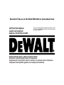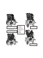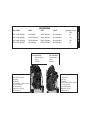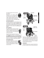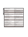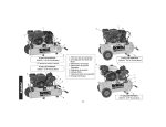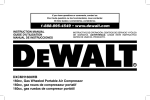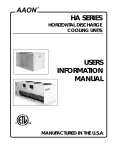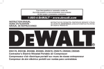
1
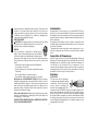
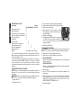
DEWALT Industrial Tool Co., 701 East Joppa Road, Baltimore, MD 21286 (FEB03) Form No. 5134370-00 Various Air Compressors Copyright © 2001
DEWALT The following are trademarks for one or more DEWALT power tools: the yellow and black color scheme; the “D” shaped air intake grill;
the array of pyramids on the handgrip; the kit box configuration; and the array of lozenge-shaped humps on the surface of the tool.
Questions? See us on the World Wide Web at www.dewalt.com
INSTRUCTION MANUAL
GUIDE D'UTILISATION
MANUAL DE INSTRUCCIONES
INSTRUCTIVO DE OPERACIÓN, CENTROS DE SERVICIO Y PÓLIZA
DE GARANTÍA. ADVERTENCIA: LÉASE ESTE INSTRUCTIVO ANTES
DE USAR EL PRODUCTO.
D55270, D55270T, D55271, D55271T, D55275, D55276
Contractor’s Gas Wheeled Portable Air Compressor
Compresseurs d’air portatif à moteur à essence sur roues de classe entrepreneur
Compresor de aire portátil a gasolina con ruedas para contratistas
1
1
2
6
5
2
3
4
7
6
3
7
4
5
8
1. Pump Air Filter
2. Engine Air Filter
3. Tank Pressure Gauge
4. Regulated Pressure Gauge
5. Pressure Regulator
6. Pilot valve
7. Safety Valve
8. Tank Drain(s)
8 GALLON PORTABLE
D55270, D55270T* - 5.5 HP Honda Engine
*Denotes 2-wheeled version.
8 GALLON PORTABLE
D55271, D55271T* - 8 HP Honda Engine
2
1
8
17 GALLON PORTABLE
D55276 - 5.5 HP Honda Engine
1
2
7
7
5
4
5
6
6
3
4
3
8
8
17 GALLON PORTABLE
D55275 - 8 HP Honda Engine
HEIGHT
D55270 160 lbs. (72.57 Kg.)
SPECIFICATIONS
WIDTH
LENGTH
Typical values @ 100 psi
CFM
25 in. (635 mm.)
18.25 in. (463.55 mm.)
43 in. (1092.2 mm.)
8.9
D55271 213 lbs. (96.62 Kg.)
27.75 in. (704.85 mm.)
18.25 in. (463.55 mm.)
43 in. (1092.2 mm.)
16.2
D55275 238 lbs. (107.96 Kg.)
33.75 in. (857.25 mm.)
20.25 in. (514.35 mm.)
43 in. (1092.2 mm.)
16.2
D55276 185 lbs. (83.91 Kg.)
31 in. (787.4 mm.)
20.25 in. (514.35 mm.)
43 in. (1092.2 mm.)
8.9
Engine Specifications
5.5 Hp Honda GX-160
8 Hp Honda GX-240
Internal Combustion
Internal Combustion
4-stroke
4-stroke
3450 RPM
3450 RPM
K Pump Specifications
G Pump Specifications
Inline, vertical twin cylinder
Single Stage
Oil Lubricated
Cast Iron crankcase, cylinder, and head
Bore: 2-1/2“ (63.5 mm)
Stroke: 2” (50.8 mm)
Weight: 47 lbs. ( 21.32 kg.)
Oil Capacity: 14 oz.
V - twin 4 cylinder
Single Stage
Oil Lubricated
Cast Iron crankcase, cylinder, and head
Bore: 2-1/2 “ (63.5 mm)
Stroke: 2-3/8” (60.33 mm)
Weight: 69 lbs. (31.3 kg.)
Oil Capacity: 30 oz.
1
English
MODEL WEIGHT
English
IF YOU HAVE ANY QUESTIONS OR COMMENTS ABOUT THIS
OR ANY DEWALT TOOL, CALL US TOLL FREE AT 1-800-4DEWALT (1-800-433-9258).
WARNING! READ AND UNDERSTAND ALL INSTRUCTIONS
BEFORE OPERATING THIS COMPRESSOR. Failure to follow all
instructions listed below may result in electric shock, fire and/or serious
personal injury.
Section VIII, Div. 1 rules. All pressure vessels should be
inspected once every two years. To find your state
pressure vessels inspector, look under the Division of
Labor and Industries in the government section of a
phone book or call 1-800-4DEWALT for assistance.
The following conditions could lead to a weakening of
the tank, and result in a violent tank explosion:
1. Failure to properly drain condensed water from the tank can
causing rust and thinning of the steel tank. Drain tank daily or
after each use. If tank develops a leak, replace it immediately with
a new tank or new compressor outfit.
2. Modifications or attempted repairs to the compressor tank.
Never drill into, weld, or make any modifications to the tank or its
attachments.
3. Do not modify the safety valve, or any other components that
control tank pressure. The tank is designed to withstand specific
operating pressures. Never make adjustments or parts substitutions to alter the factory set operating pressures.
ATTACHMENTS & ACCESSORIES
Exceeding the pressure rating of air tools, spray
guns, air operated accessories, tires and other
inflatables can cause them to explode or fly apart,
and could result in serious injury. Follow the
equipment manufacturers recommendation and
never exceed the maximum allowable pressure
rating of attachments. Never use the compressor to
inflate small low-pressure objects such as children’s
toys, footballs, basketballs, etc.
RISK OF EXPLOSION OR FIRE
Always operate the compressor in a well-ventilated area free of
combustible materials, gasoline or solvent vapors. If sparks from
compressor come into contact with flammable vapors, they may ignite,
causing fire or explosion. If spraying flammable materials, locate
compressor at least 20 feet up wind from spray area. An additional
length of hose may be required.
SAVE THESE INSTRUCTIONS
Safety Instructions
WARNING: Some dust created by this product contains chemicals
known to State of California to cause cancer, birth defects or other
reproductive harm. Some examples of these chemicals are:
• compounds in fertilizers
• compounds in insecticides, herbicides and pesticides
• arsenic and chromium from chemically treated lumber
To reduce your exposure to these chemicals, wear approved safety
equipment such as dust masks that are specially designed to filter out
microscopic particles.
WARNING: Use of this product will expose you to chemicals known
to the State of California to cause cancer, birth defects and other
reproductive harm. Avoid inhaling vapors and dust, and wash
hands after using.
WARNING: This product contains chemicals, including lead, known
to the State of California to cause cancer, and birth defects or other
reproductive harm. Wash hands after handling.
The user of the air compressor must understand these instructions.
Each person operating the air compressor must be of sound mind and
body and must not be under the influence of any substance, which
might impair vision, dexterity, or judgement.
AIR TANK
The tank on your Air Compressor is designed and may be UM coded
(for units with tanks greater than 6 inch diameter) according to ASME
2
HOT SURFACES
GASOLINE
ENGINE
ENGINE
MUFFLER
COMPRESSOR
CYLINDER & HEAD
PUMP
CRANKCASE
RISK FROM FLYING OBJECTS
The compressed air stream can cause soft tissue damage to exposed
skin and can propel dirt, chips, loose particles and small objects at high
speed, resulting in serious injury. Always wear ANSI Z28.1 approved
safety glasses with side shields when using the compressor. Never
direct air stream at people or animals. Use only OSHA approved air
blow guns.
HOT SURFACES
ENGINE
MUFFLER
RISK TO BREATHING
The compressed air from your compressor is not safe for
breathing! The air stream may contain carbon monoxide,
toxic vapors or solid particles. Never inhale air from the
compressor either directly or from a breathing device
connected to the compressor.
Sprayed materials such as paint, paint solvents, paint
remover, insecticides, weed killers, etc. contain harmful vapors and
poisons. NOTE: Operate air compressor only in a well ventilated area.
Read and follow the safety instructions provided on the label or safety
data sheets for the material you are spraying. Use a NIOSH/MSHA
approved respirator designed for use with the specific application.
RISK FROM MOVING PARTS
The compressor is designed to run continuously.
Always turn off the compressor, bleed pressure from
the air hose and tank, and disconnect from power
source before performing maintenance or attaching
tools and accessories.
AFTERCOOLER
COMPRESSOR
CYLINDER & HEAD
ENGINE
HEAD
AFTERCOOLER
PUMP
CRANKCASE
Keep your hair, clothing, and gloves away from moving parts. Loose
clothes, jewelry, or long hair can be caught in moving parts. Air vents
may cover moving parts and should be avoided as well. Do not
remove the protective covers from this product. Never operate
compressor with guards or protective covers that are damaged or
removed. Never stand on the compressor.
3
HOT SURFACES
Touching exposed metal such as the compressor head or aftercooler
can result in serious burns. Never touch any exposed metal parts on
English
Store flammable materials in a secure location away
from compressor.
Restricting any of the compressor ventilation
openings will cause serious overheating and could
cause fire. Never place objects against or on top of
compressor. Operate compressor in an open area at
least 3 feet away from any wall or obstruction that
would restrict the flow of fresh air to the ventilation openings.
English
Introduction
compressor during or immediately after operation. Compressor will
remain hot for several minutes after operation. Do not move the
compressor while it is running. Hot motor parts could cause burns
contributing to the dropping of the compressor, damaging the
compressor and/or injuring the operator.
Congratulations on the purchase of your new DEWALT Air Compressor! You can be assured that this tool has been constructed with
the highest level of precision and accuracy. Each component has been
rigorously tested to ensure the quality, endurance and performance of
this air compressor.
By reading and following the safety, operation, maintenance and
troubleshooting steps described in this manual, you will receive years
of trouble free operation.
The manufacturer reserves the right to make changes in price, color,
materials, equipment specifications or models at any time without
notice.
RISK FROM NOISE
CAUTION: Wear appropriate personal hearing protection during
use. Under some conditions and duration of use, noise from
this product may contribute to hearing loss.
ENGINE
Your air compressor is powered by a Honda® gasoline
engine. Most accidents with engines can be prevented if
you follow all instructions in this manual, the engine owner’s
manual and on the engine. Some of the most common hazards are
discussed herein, along with the best way to protect yourself and
others:
• Know how to stop the engine quickly, and understand
the operation of all controls.
• Never permit anyone to operate the engine without proper
instructions.
• Do not allow children to operate the engine.
• Keep children and pets away from the area of operation.
Refuel with care: ALLOW ENGINE TO COOL. Gasoline is extremely
flammable, and gasoline vapor can explode. Refuel outdoors, in a wellventilated area, with the engine off. Never smoke near gasoline, and
keep other flames and sparks away. Always store gasoline in an
approved container. If any fuel is spilled, move compressor to another
location before starting the engine.
Carbon Monoxide Hazards: Exhaust gas contains poisonous carbon
monoxide. Avoid inhalation of exhaust gas. Never run the engine in a
closed garage or confined area.
ALWAYS STORE COMPRESSOR IN A HORIZONTAL POSITION,
ON ALL FOUR RUBBER MOUNTS.
Inspection of Compressor
Inspect for signs of obvious or concealed freight damage. Report any
damage to the delivering freight carrier immediately. Be sure that all
damaged parts are replaced and any mechanical problems are
corrected prior to the operation of the air compressor. The air
compressor serial number is located on the deck of the air compressor
and pump bearing cap. Please write the serial number in the space
provided in the service section for future reference.
Features
PILOT VALVE
Pilot valves are used to maintain a
constant pressure range while running
continuously. The pilot valve may be
used to operate a discharge line
unloader or an unloading device in the
compressor head. The DEWALT compressor unloads through the compressor head. Unloading occurs when the receivers (tanks) reach a
preset cut-out pressure. The pilot valve opens, actuating the unloading
device that allows the compressor to run in an unloaded mode. When
the tank pressure drops to the preset cut-in pressure, the pilot valve
closes allowing the unloading device to close and the compressor once
again pumps into the tanks.
4
SAFETY RELIEF VALVE
This valve (A) is designed to prevent system failures
by relieving pressure from the system when the
compressed air reaches a predetermined level. The
valve is preset by the manufacturer and must not be
removed or modified in any way.
AIR INTAKE FILTER(S)
The filter(s) (B) are designed to clean air entering the
pump. To ensure the pump continually receives a clean,
cool, and dry air supply the filter(s) must always be
clean and the filter intake must be free from
obstructions.
PILOT VALVE CUT-OUT PRESSURE ADJUSTMENT
NOTE: Unit can remain running while performing this adjustment
WARNING : Aftercooler, pump head, and surrounding parts are
very hot; do not touch. (see the Hot Surfaces identified on page 2)
WARNING - Moving Parts: Keep your hair, clothing and gloves
away from moving parts. Loose clothing, jewelry, or long hair can be
caught in moving parts. Air vents may cover moving parts and should
be avoided as well. Do not remove the protective covers from this
product.
WARNING : The pilot valve is brass which is a soft metal. Do not
overtighten screw as threads can strip out.
1. Hold “I” firmly and loosen nut “H”.
WARNING : Do not loosen screw “G” more than 1 revolution as
screw is subjected to tank pressure and can burst out which can harm
the user or surrounding personnel.
2. Turn screw “G” clockwise to
G H I J
increase cut-out pressure limit or
counter clockwise to decrease
cut-out pressure. (example: if the
cut-out pressure on the tank
gauge reads 120 psi. and desired
cut out is 130 psi, turn screw “G” clockwise)
3. Drain air from tanks through drain valves until pump begins to
charge tanks.
4. Close drain valves.
5. Monitor cut-out pressure to verify the new setting
6. Once setting is complete hold screw “G” firmly
7. Hold “G” firmly and tighten nut “H”
A
B
AIR TANK DRAIN VALVE(S)
The drain valve(s) (C) are used to remove
moisture from the air tank after the air
compressor is shutoff.
TANK PRESSURE GAUGE
The tank pressure gauge (D) indicates air
pressure in the air tank.
REGULATED PRESSURE GAUGE
The regulated pressure gauge (E) indicates the
air pressure available at the outlet side of the
regulator. This pressure is controlled by the
regulator and is always less or equal to the air
tank pressure.
PRESSURE REGULATOR
The regulator knob (F) controls the air pressure
coming from the air tank.
C
D
E
PILOT VALVE PRESSURE DIFFERENTIAL ADJUSTMENT
NOTE: Unit can remain running while performing this adjustment
WARNING : Aftercooler, pump head, and surrounding parts are
very hot; do not touch. (see the Hot Surfaces identified on page 2)
F
5
English
Manual Lock: The manual lock allows you to manually unload the
compressor with air pressure in the tank. To operate the unloading
device in the head, rotate the flip lever to an in-line position (dashed
lines). Be sure to return lever to the loaded position after starting the
engine or the pump will not operate at preset pressures.
English
CHECKING SAFETY RELIEF VALVE OPERATION
WARNING: Aftercooler, pump head, and surrounding parts are very
hot, do not touch. (see the Hot Surfaces identified on page 2)
1. Ensure unit is off.
2. Ensure tanks are empty by looking at tank pressure gage. Drain
tanks if necessary.
3. Grasp wire ring on safety valve.
4. Pull and release ring a few times to ensure plunger moves in and
out.
WARNING - Moving Parts: Keep your hair, clothing and gloves
away from moving parts. Loose clothing, jewelry, or long hair can be
caught in moving parts. Air vents may cover moving parts and should
be avoided as well. Do not remove the protective covers from this
product.
1. Hold “I” firmly and loosen nut “J”
WARNING : Do not loosen barrel “I” more than 1 revolution as barrel
is subjected to tank pressure and can burst out which can harm the
user or surrounding personnel.
2. Turn barrel “I” clockwise to increase differential or counter clockwise
to decrease differential. (for example: if pressure differential is 100 130 psi and 100 - 120 psi is desired, turn “I” counter clockwise)
NOTE : Too narrow of a differential can cause chatter of the pilot valve.
Increase differential to eliminate chatter.
3. Hold barrel “I”
4. Hold “I” firmly and tighten nut “J”
CHECKING AIR FILTER ELEMENT
WARNING: Aftercooler, pump head, and surrounding parts are very
hot, do not touch. (see the Hot Surfaces identified on page 2)
1. Ensure unit is off.
2. Allow unit to cool.
3. Unscrew filter top from filter base by turning counter clockwise
about 5 degrees.
4. Separate filter top from base.
5. Remove element from filter base.
6. If element needs cleaning, blow out with air. Replace element if
unsure.
7. Place element back in filter base.
8. Reconnect filter top to filter base and while pushing in, rotate top
clockwise 5 degrees.
CHECKING COMPRESSOR PUMP OIL LEVEL
WARNING: Aftercooler, pump head, and surrounding parts are very
hot, do not touch. (see the Hot Surfaces identified on page 2)
1. Ensure Unit is off.
2. Locate unit onto a flat horizontal surface.
K
3. Remove knurled filler knob (K) from crankcase.
4. Insert a clean screwdriver into the crankcase
and remove it.
5. Look for visual signs of contaminants (water,
dirt, etc.) Change pump oil if contaminants are
present.
6. Oil should not exceed top raised line on side of crankcase (oil will be
even with bottom of threads in crankcase fill port). If necessary fill
with DEWALT synthetic oil.
STARTING UNIT
Follow the pre-start and start-up procedures in the operating procedure
section.
TURNING UNIT OFF
Follow the shut-down procedure in the operating procedures section.
ADJUSTING REGULATOR
1. Pull regulator knob (L) out
6
INSTALLING HOSES
WARNING: Firmly grasp hose in hand
M
when installing or disconnecting to prevent
L
hose whip.
1. Ensure regulated pressure gage reads 0 PSI.
2. Grasp hose in hand at coupler location.
3. Pull back collar on female quick connect coupler (M) located on
compressor.
4. Push male connector into female connector.
5. Release female connector
6. Grasp hose and pull to ensure couplers are seated
7. Adjust regulator to desired pressure.
Preparation For Use
DISCONNECTING HOSES
WARNING: Firmly grasp hose in hand when installing or
disconnecting to prevent hose whip.
1. Ensure regulated pressure gage reads 0 PSI.
2. Grasp hose in hand at coupler location
3. Pull back collar on female quick connect coupler located on
compressor.
4. Pull male connector out of female connector.
5. Release female connector
INITIAL SET-UP:
Read safety instructions before setting-up air compressor.
CAUTION: Do not operate without lubricant or with inadequate
lubricant. DEWALT is not responsible for compressor failure caused by
inadequate lubrication.
Compatibility
Air tools and accessories that are run off the compressor must be
compatible with petroleum based products. If you suspect that a
material is not compatible with petroleum products, an air line filter for
removal of moisture and oil vapor in compressed air is required.
NOTE: Always use an air line filter to remove moisture and oil vapor
when spraying paint.
DRAINING TANKS
WARNING: Tanks contain high pressure air. Keep face and other
body parts away from outlet of drain. Use safety glasses when draining
as debris can be kicked up into face. Use ear protection as air flow
noise is loud when draining.
7
English
NOTE: All compressed air systems generate condensate that
accumulates in any drain point (e.g. tanks, filter, aftercoolers, dryers).
This condensate contains lubricating oil and/or substances which may
be regulated and must be disposed of in accordance with local, state,
and federal laws and regulations.
1. Ensure ON/OFF switch is in the OFF position.
2. Move compressor into an inclined position so drain valve(s) are at
the lowest point (this will assist in removing moisture, dirt, etc. from
tanks)
3. Place a suitable container under the drains to catch discharge.
4. Grasp black lever on one drain valve.
5. Slowly rotate lever so as to gradually bleed air from tank.
6. Grasp black lever on other drain valve and rotate to approximately
the same position as the first. (For twin tank units)
7. When tank pressure gauge reads 10 psi, rotate valve(s) to the fully
open position.
8. Close drain valve(s) when finished.
2. Turn knob clockwise to increase regulated
pressure and counter clockwise to
decrease regulated pressure.
3. When desired pressure is shown on the
regulated pressure gage push knob in to
lock.
English
Location
MOVING:
When moving the unit into a position for use, grasp handle grips at rear
of compressor, and lift compressor high enough so unit can be rolled
on the front tire.
WARNING: Ensure proper footing and use caution when rolling
compressor so that unit does not tip or cause loss of balance.
CAUTION: In order to avoid damaging the air compressor, do not
allow the unit to be tilted more than 10˚ when operating.
Place air compressor at least 3 feet away from obstacles that may
prevent proper ventilation. Keep unit away from areas that have dirt,
vapor and volatile fumes in the atmosphere which may clog and gum
up the intake filter and valves, causing inefficient operation.
When location is reached slowly lower rear of compressor to ground.
ALWAYS STORE COMPRESSOR IN A HORIZONTAL POSITION,
ON ALL FOUR RUBBER MOUNTS.
NOTE: Should the unit tip over, hard starting and smoking will occur
due to oil spillage.
HUMID AREAS
In frequently humid areas, moisture may form in the bare pump and
produce sludge in the lubricant, causing running parts to wear out
prematurely. Excessive moisture is especially likely to occur if the unit
is located in an unheated area that is subject to large temperature
changes. Two signs of excessive humidity are external condensation
on the bare pump when it cools down and a “milky” appearance in
compressor lubricant. You may be able to prevent moisture from
forming in the bare pump by increasing ventilation or operating for
longer intervals.
Air Inlet Filter
CAUTION: Do not operate without air inlet filter
General Requirements
The piping, fittings, receiver tank, etc. must be certified safe for at
least the maximum working pressure of the unit. Use hard welded or
threaded steel or copper pipes, cast iron fittings and hoses that are
certified safe for the units discharge pressure and temperature. Use
pipe thread sealant on all threads, and tighten joints thoroughly to
prevent air leaks. DO NOT USE PVC PLASTIC.
NOISE CONSIDERATIONS
Consult local officials for information regarding acceptable noise levels
in your area. To reduce excessive noise, use vibration mounts or
silencers, relocate the unit or construct total enclosures or baffle walls.
Contact a DEWALT service center or call 1-800-4DEWALT for
assistance.
CONDENSATE DISCHARGE PIPING
If installing a condensate discharge line, the piping must be at least one
size larger than the connection, as short and direct as possible,
secured tightly and routed to a suitable drain point. Condensate must
be disposed of in accordance with local, state and federal laws and
regulations.
NOTE: All compressed air systems generate condensate that
accumulates in any drain point (e.g. tanks, filter, aftercoolers, dryers).
This condensate contains lubricating oil and/or substances which may
be regulated and must be disposed of in accordance with local, state,
and federal laws and regulations.
TRANSPORTING:
WARNING: Unit weighs more than 160 lbs. Do not move or lift
without assistance.
When transporting the compressor in a vehicle, trailer, etc. ensure that
the tanks are drained and the unit is secured and placed on a flat
horizontal surface. Use care when driving so to avoid tipping the unit
over in the vehicle. Damage can occur to the unit or surrounding items
if unit is tipped. Use a ramp if loading or unloading the unit from a
height of more than 12".
8
Operating Procedures
SHUT-DOWN
1. Follow the “Stopping the Engine” procedures in engine owner’s
manual.
NOTE: If finished using compressor, follow steps 2 - 6 below.
2. Turn regulator knob counterclockwise until fully closed. Ensure
regulated pressure gage reads 0 PSI.
3. Remove hose and accessory.
4. Drain the air tank(s). Ensure tank pressure gage reads 0 PSI
5. Allow the compressor to cool down.
6. Wipe air compressor clean and store in a safe, non freezing area.
Maintenance
The following procedures must be followed when maintenance or
service is performed on the air compressor.
1. Turn off air compressor
2. Disconnect spark plug wire
3. Drain tank(s)
4. Allow air compressor to cool down before starting service
NOTE: All compressed air systems contain maintenance parts (e.g.
lubricating oil, filters, separators) that are periodically replaced. These
used parts may contain, substances that are regulated and must be
disposed of in accordance with local, state, and federal laws and
regulations.
NOTE: Take note of the positions and locations of parts during
disassembly to make reassembly easier.
NOTE: Any service operations not included in this section should be
performed by authorized service personnel.
START-UP
1. Ensure the ON/OFF lever on the engine is in the OFF position.
2. Pull out and turn regulator knob counterclockwise until fully closed.
Push in to lock. Regulated pressure gage should read 0 psi.
3. Ensure fuel is in fuel tank.
4. Turn the ON/OFF lever on the engine to the ON position.
5. Rotate the manual lock on the pilot valve into the in line position to
assist with start up.
6. Follow the “Starting the Engine” procedures in the engine’s owner
manual.
7. Rotate the manual lock on the pilot valve into a perpendicular
position so the pump can charge the tanks.
8. Allow compressor to pump up to “cut out” pressure.
9
English
NOTE: If any unusual noise or vibration is noticed, stop the
compressor and refer to the troubleshooting section.
9. Attach hose and accessory.
10. Adjust regulator to desired setting.
Pre-Start Checklist
1. Ensure the ON/OFF lever on the engine is in the OFF position.
2. Ensure tank(s) is/are drained so that moisture, dirt, etc. can be
eliminated.
3. Ensure tank pressure gauge reads 0 psi.
4. Ensure safety and drain valve(s) is /are functioning properly.
5. Ensure the drain valve(s) is / are closed.
6. Check oil level in pump.
7. Check oil level in engine crankcase.
8. Visually inspect drive belt. Replace belt if frayed, cracked, or worn.
9. Ensure all guards, covers, and labels are in place, legible (for
labels) and securely mounted. Do not use compressor until all items
have been verified.
English
MAINTENANCE CHART
Procedure
3.
4.
5.
6.
Locate a suitable container under drain plug (O).
Remove the knurled filler knob (N) from crankcase.
Remove the oil drain plug.
N
Allow ample time for all oil to drain out. (Tilting
the compressor towards the drain plug will
assist in draining.)
7. Install the oil drain plug.
8. Fill pump with DEWALT synthetic compressor
O
oil. Oil should not exceed top raised line on
side of crackcase. (Oil will be even with bottom of threads in
crankcase fill port.)
9. Install knurled filler knob.
I Year or
Day Week Month 200 Hrs.
Check pump oil level
X
Oil leak inspection
X
Drain condensation in air tank(s) X
Check for unusual noise/vibration X
Check for air leaks*
X
Inspect belt
X
Inspect air filter
X
Clean exterior of compressor
X
Check safety relief valve
X
Check belt adjustment
X
Change pump oil **
X
Engine
See engine owner’s manual.
* To check for air leaks apply a solution of soapy water around joints.
While compressor is pumping to pressure and after pressure cuts out,
look for air bubbles to form.
** The pump oil must be changed after the first 20 hours or operation.
Thereafter, when using DEWALT synthetic oil, change oil every 200
hours of operation or once a year, whichever comes first. In harsh
environments, maintenance must be performed on a more accelerated
schedule.
CHECKING BELT TENSION
WARNING : Aftercooler, pump head, and surrounding parts are
very hot; do not touch. (see the Hot Surfaces identified on page 2)
1. Ensure unit is off and unplugged from wall.
2. Allow unit to cool down so pump can be touched.
3. FOR K PUMP UNITS
Remove six belt guard mounting fasteners (2 on the pump head
and 4 on the deck)
FOR G PUMP UNITS
Remove seven belt guard mounting fasteners (2 on the pump head,
1 J-hook, and 4 on the deck)
4. Remove guard.
5. Place a 12" ruler perpendicular to belt and at the middle of the
longest span.
6. Push up and down on the belt in the middle of the span with
approximately 8 lbs. of force and notice the amount of deflection
using the ruler. Belt should not move more than 1/2"; if so, see
ADJUSTING BELT TENSION section.
7. Replace belt guard
COMPRESSOR PUMP OIL CHANGE
NOTE: Pump oil contains substances that are regulated and must be
disposed of in accordance with local, state and federal laws and
regulations.
WARNING : Aftercooler, pump head, and surrounding parts are very
hot; do not touch. (see the Hot Surfaces identified on page 2)
1. Ensure unit is off.
2. Allow the unit to cool.
10
Repairs
To assure product SAFETY and RELIABILITY, repairs, maintenance
and adjustment should be performed by authorized service centers or
other qualified service organizations, always using identical replacement parts.
Full One Year Warranty
DEWALT heavy duty industrial tools are warranted for one year from
date of purchase. We will repair, without charge, any defects due to
faulty materials or workmanship. For warranty repair information, call
1-800-4-DEWALT. This warranty does not apply to accessories or
damage caused where repairs have been made or attempted by
others. This warranty gives you specific legal rights and you may have
other rights which vary in certain states or provinces.
FREE WARNING LABEL REPLACEMENT: If your warning labels
become illegible or are missing, call 1-800-4-DEWALT for a free
replacement.
SAVE THESE INSTRUCTIONS
FOR FUTURE USE
Accessories
Recommended accessories for use with your tool are available for
purchase from your local dealer or authorized service center. If you
need assistance in locating any accessory for your tool, contact:
DEWALT Industrial Tool Co., 701 East Joppa Road, Baltimore, MD
21286 or call 1-800-4- DEWALT.
CAUTION: The use of any other accessory not recommended for
use with this tool could be hazardous.
Service Information
Please have the following information available for all service calls:
Model Number _____________Serial Number _______________
Date and Place of Purchase _____________________________
11
English
ADJUSTING BELT TENSION
WARNING: Pump and surrounding components are hot.
1. Follow procedures 1-4 in checking belt tension section.
2. Scribe a mark at the base of the pump on the deck to be used as
a reference.
3. Loosen four pump mounting bolts.
4. Remove the belt.
5. Scribe a mark approximately 1/8" from the original mark.
6. Slide the pump to the new mark and retighten the pump mounting
bolts.
WARNING : Use caution when rolling belt onto flywheel as fingers
can get caught between the belt and flywheel.
7. With the pump secure, roll the belt over the flywheel and the pulley.
8. Check the belt tension again.
9. If tension is good, retighten the engine brace and replace belt
guard.
English
Troubleshooting Guide
This section provides a list of the more frequently encountered malfunctions, their causes and corrective actions. The operator or
maintenance personnel can perform some corrective actions, and others may require the assistance of a qualified DEWALT technician
or your dealer.
Problem
Code
Abnormal piston ring or cylinder wear ............................................................................................2,5,6,11,12,14
Unit does not come up to speed; unit is slow to come up to speed................................................3,4,8,15,17,20,21,25
Unit runs excessively hot ................................................................................................................1,2,5,9,14,17
Excessive noise during operation ..................................................................................................3,4,5,8,9,10,11,12,16,21,25,26
Excessive starting and stopping ......................................................................................................3,8,17,20,21,25,30
High oil consumption........................................................................................................................1,4,6,10,11,12,13,16,25,27,28
Knocking or rattling ..........................................................................................................................2,5,6,9,19,11,12,16,25,26
Moisture in crankcase or "milky" appearance in petroleum lubricant or rusting in cylinders ..........6,7,10,11,12,16,20,21,25,29,31
Oil in discharge air (oil pumping) ....................................................................................................2,6,8,10,11,16,27
Oil leaking from shaft seal................................................................................................................13
Safety relief valve "pops" ................................................................................................................18,19
Compressor will not run or restart....................................................................................................32,35
Air leaks at pump ............................................................................................................................20
Air leaks at fittings ............................................................................................................................21
Air leaks from tank ..........................................................................................................................22
Insufficient pressure at air tool or accessory ..................................................................................1,3,17,23,24
Air compressor not making enough air............................................................................................1,3,4,8,10,11
Moisture in discharge air..................................................................................................................30,31
Compressor stalls ............................................................................................................................34
Receivers are not filling with air ......................................................................................................35
12
TROUBLESHOOTING CODES
16
17
Possible Solution
Clean or replace air inlet or discharge line filter.
Drain existing lubricant and refill with DEWALT Synthetic lubricant.
Check tubing and connections.
Drain existing lubricant and refill with DEWALT Synthetic lubricant.
Add lubricant to crankcase to proper level. Check for bearing damage.
Drain existing lubricant and refill with DEWALT Synthetic lubricant.
Run unit for longer duty cycles.
Inspect valves. Clean or replace as required.
Clean piston. Repair or replace as required.
Install new rings.
Repair or replace as required.
Inspect all. Repair or replace as required
Replace seal or crankshaft assembly.
Install more effective filtration or relocate the compressor.
Relocate compressor to warmer environment. Ensure that DEWALT
synthetic oil is in crankcase.
Deglaze cylinder with 180 grit flex-hone.
Check accessory air requirement. If higher than the CFM or pressure
supply of air compressor, then larger air compressor is required.
Worn compressor cylinder finish.
Air compressor is not large enough for air required.
13
English
Code Possible Cause
1
Clogged or dirty inlet and/or discharge line filter.
2
Lubricant viscosity too low.
3
Air leaks in air discharge piping.
4
Lubricant viscosity too high.
5
Lubricant level too low.
6
Detergent type lubricant being used.
7
Extremely light duty cycles.
8
Compressor pump check valve leaky, broken,carbonized
or loose.
9
Carbon build up on top of piston.
10
Piston rings damaged or worn (broken, rough, or scratched).
Excessive end gap or side clearance. Piston rings not seated,
stuck in grooves or end gaps not staggered.
11
Cylinder or piston scratched, worn, or scored.
12
Connecting rod, piston pin,
or crankpin bearings worn or scored.
13
Compressor crankshaft seal worn or crankshaft scored.
14
Extremely dusty atmosphere.
15
Ambient temperature too low.
English
Code Probable Cause
18
Possible defective safety/relief valve.
19
20
21
Excessive air tank pressure.
Defective gaskets.
Fittings not tight enough.
22
23
24
25
Defective or rusted air tank
Pressure regulator knob not turned to high enough pressure
or defective pressure regulator.
Hose or hose connections are to small or long.
Possible defective (reed) valve.
26
Air compressor on uneven surface.
27
28
29
30
Crankcase overfilled with oil.
Plugged oil dipstick vent.
Water in oil due to condensation.
Condensation in air tank caused by high level of
atmospheric humidity.
Unit located in damp or humid location.
Engine oil too low. Low oil shut off is on.
Manual lock on pilot valve is in the loaded position.
Engine idle speed too low.
Engine problem.
31
32
33
34
35
Probable Solution
Operate safety relief valve manually by pulling on test ring. If it still
leaks, replace it.
Adjust the pilot valve. If the problem still exists, replace pilot valve.
Replace and torque head bolts to 6 - 7 ft lbs.
Warning : Drain air before tightening. tighten fittings so air can not
be heard escaping. Check joint with soap solution. Do not
overtighten.
Air tank must be replaced. Do not attempt to repair air tank.
Adjust pressure regulator knob to proper setting or replace.
Replace with larger hose or connectors.
Remove pump head and inspect valve plate and (reed) valve.
Clear or replace valves as required.
Do not incline the air compressor more than 10˚ in any direction
while running.
Drain oil, Refill to proper level with DEWALT synthetic oil.
Clean.
Drain oil. Refill to proper level with DEWALT synthetic oil.
Drain air tank after every use. Drain air tank more often in humid
weather and use an air line filter.
Relocate the compressor.
Add engine oil.
Move manual lock into an in-line position.
Increase idle speed.
See “Taking care of unexpected problems” in engine owners
manual.
14