1
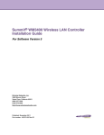
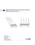
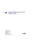
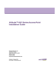
(3)
5
The AP3550 can be mounted to a pole (1.5 - 18 inches in diameter) or to a
wall. The AP3550 Wall Mounting Kit (Part No. 15733) is not included with
AP3550 and must be ordered separately.
The mounting bracket has four parts: one rectangular plate used for pole
and wall mounting, one square plate that attaches directly to the AP3550
and two plates forming an adjustable V-shaped clamp for pole mounting.
4
(4)
(5)
(6)
Attach the AP3550 and mounting plate to the bracket already fixed to
the pole. If necessary, use the “U-bracket” (included in the mounting
kit), in conjunction with the band clamp, to expand the diameter of the
bracket to a maximum if 18 inches.
Secure the AP3550 to the pole.
Mounting the AP3550
$WWDFKWKHVTXDUH
SODWHWRWKHEULGJH
Attach the square mounting plate to the access point with the supplied
screws.
5
2
3
4
Drill four holes in the wall that match the screws and wall plugs.
Secure the bracket to the wall.
Attach the square mounting plate to the AP3550 with the supplied
screws. Attach the AP3550 to the plate on the wall.
Secure the AP3550 to the bracket. Fit the edges of the V-shaped clamp
parts into the slots on the flat side of the rectangular plate.
Fit the edges of the
V-shaped part into the slots
2
Mounting the AP3550 on a Pole
The AP3550 is a ruggedized access point designed for outdoor
deployments. The AP3550 employs a dual-mode simultaneous 802.11a and
802.11g radio solution.
1
1
Ensure the AP3550 is oriented properly, and attach the bracket to a
wall with flat side flush against the wall. Position the bracket in the
intended location and mark the positions of the four mounting screw
holes.
Mounting the AP3550 on a Wall
Note: The AP3550 tilt angle may need to be adjusted during the antenna
alignment process. Verify the antenna polarization angle when installing, and
ensure the antennas are oriented correctly in respect to the AP3550's coverage
area.
Antenna Specifications
for selection of the recommended external antennas see the Altitude™
35xx/45xx AP Antenna Selection Guide available from
http://www.extremenetworks.com/go/documentation
Caution: The recommended 2.4 and 5.5 GHz antenna models are rated for
the AP3550 model access point and its intended outdoor deployment. The
models are not intended for use on an AP3510 model access point.
Physical Specifications
Dimensions 12 inches long x 8.25 inches wide x 3.5 inches thick
Housing Aluminum
Weight 4 lbs.
Environmental Specifications
Temperature-30°C to 55°C (Operating), -40°C to 85°C (Storage)
Humidity 5% to 95% Non-condensing (both Operating and Storage)
Altitude8,000 feet/2438 m @28°C (Operating)
15,000 feet/4572 m @12°C (Storage)
Electrostatic Discharge15kV (air) @ 50% rh, 8kV (contact) @ 50% r
DropBench drop 36 inches to concrete
Wind Blown Rain40 MPH @ 0.1inch/minute, 15 minutes
Rain/Drip/SpillIPX6 Spray @ 4L/minute, 10 minutes
DustIP5X 20mb vacuum max, 2 hours, stirred dust, .88g/m^3
Technical Specifications
AccessAdapt, Alpine, Altitude, BlackDiamond, EPICenter, ExtremeWorks
Essentials, Ethernet Everywhere, Extreme Enabled, Extreme Ethernet
Everywhere, Extreme Networks, Extreme Standby Router Protocol,
Extreme Turbodrive, Extreme Velocity, ExtremeWare, ExtremeWorks,
ExtremeXOS, Go Purple Extreme Solution, ExtremeXOS ScreenPlay,
ReachNXT, Sentriant, ServiceWatch, Summit, SummitStack, Triumph,
Unified Access Architecture, Unified Access RF Manager, UniStack, the
Extreme Networks logo, the Alpine logo, the BlackDiamond logo, the
Extreme Turbodrive logo, the Summit logos, and the Powered by
ExtremeXOS logo are trademarks or registered trademarks of Extreme
Networks, Inc. or its subsidiaries in the United States and/or other
countries.
sFlow is a registered trademark of InMon Corporation.
Specifications are subject to change without notice.
All other registered trademarks, trademarks, and service marks are
property of their respective owners.
© 2009 Extreme Networks, Inc. All Rights Reserved.
3
Electrical Specifications
Nominal Operating Voltage 48Vdc
Nominal Operating Current 250mA
Tighten the
securing bolts
The AP3550 has a separate LAN and WAN port for connecting to the
network and receiving power (over the AP3550’s LAN port only). The
AP3550 has four antenna connectors (on top) supporting 802.11a and
802.11g antenna options. However, the AP3550 antenna suite is designed
for outdoor deployments, so the existing AP3510 antenna suite should not
be used with an AP3550. The AP3550’s mode of operation is identical to
the AP3510’s.
To the Installer
This guide is intended for the professional end users or technicians
responsible for installing the AP3550 model access point. It assumes the
technician is familiar with basic Ethernet LAN-based networking and
device installation concepts. This guide provides specifications, procedures
and guidelines to use during the installation process. This guide does not
provide site-specific installation procedures. For detailed site-specific
installation procedures, refer to the site-specific documentation derived
from site survey and site network analysis.
Altitude™ 3550 Access Point
Installation Guide
Note - This AP3550 Installation Guide is intended to assist professional
installers with the installation of the AP3550. Once secured in its intended
operational position, refer to the AP35xx Product Reference Guide for detailed
instructions on configuring the access point’s feature set. For more information,
go to http://www.extremenetworks.com/go/documentation.
Verifying Package Contents
Inspect the contents and report any missing or damaged items to your
sales representative.
The AP3550 access point ships with the following components:
● 1 AP3550 802.11 a+bg dual-radio access point (AP3550-US Part No.
15722 AP3550-ROW Part No. 15726)
● 1 AP3550 Installation Guide (this document)
● 1 set of cable connectors
● 3 antenna connector dust covers
● 2 connector cover AP67 jacks, plus chain_LTW-M9/14-SB
Note: An RJ-45 to Serial (9-pin D) cable is required to make a connection to the
AP3550’s Console port. This cable is not supplied and must be provided by the
customer. The pinouts for this cable are shown in the following table.
Extreme Networks, Inc.
3585 Monroe Street
Santa Clara, CA 95051
(888) 257-3000
(408) 579-2800
http://www.extremenetworks.com
8
DB9
1
RJ-45
2
6
3
2
4,5
6
5
3
7
4
8
If using a single-port Power-Over-Ethernet solution to supply power to the
AP3550, the AP3550 Power Tap (Part No. 15729) must be used. This singleport power injector is designed specifically for outdoor use with the
AP3550.
Safety Information
Before operating any equipment, review this document for any hazards
associated with installation and use of the device. Also, review standard
practices for preventing accidents.
● Only trained and qualified personnel should install and remove the
Power Injector.
● The power cord must be a three-conductor type (two current carrying
conductors and one ground conductor) terminated on one end by an
IEC 60320 appliance coupler (for Power Injector connection) and on
the other end by a plug containing a ground (earth) contact.
● The power cord must be rated for a minimum of 250VAC RMS
operation, with a minimum rated current capacity of 5A [or a
minimum wire gauge of 18AWG (0.75mm²)].
● The AC wall-socket outlet must be near the Power Injector and easily
accessible.
● The Power Injector Data and Data & Power interfaces are qualified as
SELV (Safety Extra-Low Voltage) circuits according to IEC 60950. These
interfaces can only be connected to SELV interfaces on other
equipment.
Warnings
●
●
●
7
To mount the AP3550 access point to a pole (1.5 - 18 inches in diameter) or
wall, an AP3550 Mounting Kit (Part No. 15733) can be separately ordered.
This kit contains the brackets and accessories required to mount the access
point.
If installing the AP3550 in an outdoor area prone to high winds and rain,
Extreme Networks recommends using the AP3550 Heavy Weather Kit
(Part No. 15732). This kit affords additional protection to shield an AP3550
from high wind and water damage as a result of driving rain.
Published: December 2009
Part Number: 100349-00 Rev 01
Product Description
Ensure the AP3550 is oriented properly, and fit the edges of the Vshaped clamp parts into the slots on the flat side of the rectangular
plate.
Place the V-shaped bracket clamp parts around the pole and tighten
the nuts just enough to hold the bracket to the pole. (The bracket may
need to be rotated around the pole during the antenna alignment
process).
Introduction
●
●
Read the installation instructions before connecting the Power Injector
to a power source.
Follow basic electricity safety measures whenever connecting the
Power Injector to its power source.
This product relies on the building installation for short-circuit (over
current) protection. Ensure a fuse or circuit breaker no larger than 120
VAC, 3A U.S. (240VAC, 1.5A international) is used on the phase
conductor.
A voltage mismatch can cause equipment damage and could pose a
fire hazard. If the voltage indicated on the label is different from the
power outlet voltage, do not connect the Power Injector to that
particular outlet.
The Power Injector Data In and Data & Power Out ports are shielded
RJ-45 sockets. Only RJ-45 data connectors should be connected to these
sockets.
(1)
(2)
AP3550 LEDs
Extreme Networks Technical Assistance Centers (TAC) provide 24x7x365
worldwide coverage. These centers are the focal point of contact for postsales technical and network-related questions or issues. TAC will create a
Service Request (SR) number and manage all aspects of the SR until it is
resolved. For a complete guide to customer support, see the Technical
Assistance Center User Guide at:
http://www.extremenetworks.com/go/TACUserGuide
The Extreme Networks eSupport website provides the latest information
on Extreme Networks products, including the latest Release Notes,
troubleshooting, downloadable updates or patches as appropriate, and
other useful information and resources. Directions for contacting the
Extreme Networks Technical Assistance Centers are also available from the
eSupport website at:
https://esupport.extremenetworks.com
The AP3550 access point has four LEDs matching the functionality of the
AP3510 model access point. However, the AP3550’s LEDs are on the
bottom of the access point.
Power and error conditions (split LED)
Data over Ethernet
802.11a radio activity
802.11b/g radio activity
Registration
If you have not already registered with Extreme Networks using a
registration card supplied with your product, you can register on the
Extreme Networks website at:
http://www.extremenetworks.com/go/productregistration.
Documentation
Check for the latest versions of documentation on the Extreme Networks
documentation website at:
http://www.extremenetworks.com/go/documentation
Regulatory Information
sy
The AP3550’s LEDs have the following display and functionality:
● Power Status - Solid white indicates the AP3550 is adequately powered.
● Error Conditions - Solid red indicates the AP3550 has a problem
requiring attention.
● Ethernet Activity - Flashing white indicates data transfers and Ethernet
activity.
● 802.11a Activity - Flickering amber indicates beacons and data transfers
over the radio.
● 802.11b/g Activity - Flickering green indicates beacons and data
transfers over the radio.
All Extreme Networks devices are designed to be compliant with rules and
regulations in locations of intended sale and are labeled as required by the
authorizing agency. Any changes or modifications to Extreme Networks
equipment, not expressly approved by Extreme Networks, could void the
user's authority to operate the equipment.
When Extreme Networks devices are professionally installed the Radio
Frequency Output Power will not exceed the maximum allowable limit for
the country of operation when properly installed.
Antennas: Use only the supplied or an approved replacement antenna.
Unauthorized antennas, modifications, or attachments could cause damage
and may violate regulations.
(7)
Note: When starting the access point in cold weather (below -30°C), there might
not be any LED indicator activity, even though the access point may be
receiving power.
Powering the Access Point
An AP3550 model access point receives power via an Ethernet cable
connected to the AP3550’s LAN port (using unused pairs).
When users purchase an Extreme Networks WLAN solution, they often
need to place access points in obscure locations. In the past, a dedicated
power source was required for each access point in addition to the Ethernet
infrastructure. This often required an electrical contractor to install power
drops at each access point location. An approved solution merges power
and Ethernet into one cable, reducing the burden of installation and allows
optimal access point placement in respect to the intended radio coverage
area.
The AP3550 model access point is powered using the Extreme Networks
Power Tap (Part No. 15729). The Power Tap is a ruggedized solution
designed for outdoor deployments. The Power Tap may be deployed
outdoors at the access point location, or deployed indoors to inject power
over the Ethernet cable to an AP3550 located outdoors.
A Power Tap receives power and is ready for AP3550 connection and
operation as soon as AC power is applied. There is no On/Off switch.
Caution - The AP3550 accepts Power over Ethernet only on un-used pairs.
Using the wrong power solution (including a non-compliant POE system or a
solution not rated for outdoor use) could severely damage the AP3550 and
void the product warranty.
Caution - For Power Tap installations, an electrician is required to open the
unit, feed the power cable through the Line AC connector, secure the power
cable to the unit’s three screw termination block and tighten the unit’s Line
AC clamp (by hand) to secure the power cable. Only a certified electrician
should conduct the installation. Additionally, an electrician must attach a
ground cable between the EARTH GROUND connector (on the back of the
unit) to a suitable earth ground connection as defined by your local
electrical code.
Customer Support
Note - Services can be purchased from Extreme Networks or through one of its
channel partners. If you are an end-user who has purchased service through an
Extreme Networks channel partner, please contact your partner first for support.
(8)
Power Supply
The AP3550 access point receives power via an Ethernet cable connected to
the RJ45 LAN port (using unused pairs). Extreme Networks recommends the
model 15729 Power Tap-Altitude 3550 to be used to provide power to the
AP3550 access point. The Power Tap is a ruggedized solution designed for
outdoor deployments. It is pre-approved for use with the AP3550 and is
compliant with several international safety, EMC and Environmental
standards. Refer to http://www.extremenetworks.com/go/rfcertification/htm for
approved country list.
Caution - Use only an Extreme Networks approved power supply. Use of an
alternative power supply may invalidate any approval given to this device and
may be dangerous if not properly tested and approved by local agency.
Wireless Devices - Countries
Country Selection. The Extreme Networks AP3550 Access Point is
manufactured as 2 model numbers. The location of installation will determine
the appropriate model number to choose. Due to unique regulatory
requirements within the United States only the United States will appear in
the country list upon initial set up. The AP3550-ROW 11abg will list many
countries where it is the professional installer and end users responsibility to
properly pick the correct country of use and set up the AP in accordance with
all instructions provided.
● 15722 AP3550-US 11abg AP (For use in US only)
● 15726 AP3550-ROW 11abg AP (For use in Europe & Rest of World)
The outdoor use of an 802.11abg access point may be allowed but it does
have frequency restrictions and may require a license for operation. Please
refer to all instructions to properly set up this AP to ensure proper use.
Contact local country Authority for procedure to follow and regulatory
information. For details on approved countries please visit
http://www.extremenetworks.com/go/rfcertification.htm or contact Extreme
Networks.
Warning: - Select only the country in which you are using the device. Any
other selection will make the operation of this device illegal. The professional
installer and end user are responsible to properly follow all instructions and
warning when installing this device.
United States
The Extreme Networks 15722 AP3550-US Access Point is dedicated for use in
the United States under rules of the FCC. Other countries may use the model
if they agree with FCC operating frequencies and powers applicable to this
model.
The use on UNII (Unlicensed National Information Infrastructure) Band 1
5150-5250 MHz is restricted to indoor use only, any other use will make the
(9)
Country Approvals
Regulatory markings & ID# have been applied to the device product label
signifying the radio (s) are approved for use in the country list located at
http://www.extremenetworks.com/go/rfcertification.htm. This list of countries is
extensive and includes but is not limited to United States, Canada, Australia,
Japan, Europe and China. Operation of the device without appropriate
regulatory approvals is illegal.
Health and Safety Recommendations
Warnings for the use of Wireless Devices
Please observe all warning notices with regard to the usage of
wireless devices.
Potentially Hazardous Atmospheres
You are reminded to observe restrictions on the use of radio devices in fuel
depots, chemical plants etc. and areas where the air contains chemicals or
particles (such as grain, dust, or metal powders) and any other area where
you would normally be advised to turn off your vehicle engine.
Safety in Hospitals
Wireless devices transmit radio frequency energy and may affect
medical electrical equipment. When installed adjacent to other
equipment, it is advised to verify that the adjacent equipment is not
adversely affected.
FCC / EU RF Exposure Guidelines
Safety Information. The device complies with internationally recognized
standards covering human exposure to electromagnetic fields from radio
devices.
Reducing RF Exposure—Use Properly. It is advisable to use the device only in
the normal operating position as described in this guide.
Remote and Standalone Antenna Configurations. To comply with FCC RF
exposure requirements, antennas that are mounted externally at remote
locations or operating near users at stand-alone desktop of similar
configurations must operate with a minimum separation distance of 20 cm
from all persons.
(10)
To reduce potential radio interference to other users, the antenna type and
its gain should be so chosen that the equivalent isotropically radiated
power (EIRP) is not more than that permitted for successful
communication.
This device has been designed to operate with the antennas listed in the
Altitude™ 35xx/45xx AP Antenna Selection Guide available from
http://www.extremenetworks.com/go/documentation, and have a maximum
gain of 9dBi (2.4GHz) and 10dBi (5GHz). Antennas not included in this
guide, or having a gain greater than 9dBi (2.4GHz) and 10dBi (5GHz) are
strictly prohibited for use with this device. The required antenna
impedance is 50 ohms.
Label Marking: The Term "IC:" before the radio certification signifies that
Industry Canada technical specifications were met.
European Economic Area (EEA)
CE Marking. The Altitude model AP3550-ROW 11abg AP is uniquely
designed for use in the European Union and other countries with similar
regulatory restrictions where the end user or installer is allowed to
configure the Altitude AP for operation by selecting a specific country
from a list of countries. Upon connection to the controller, software will
prompt the user to select a country. After the country is selected, the
controller will set up the Altitude AP with the proper frequencies and
power outputs for that country as required by authorities. It is the
professional user or installer’s responsibility to ensure the proper set up of
the AP to correct channel limitations, indoor/outdoor restrictions, license
requirements, and operation within power level limits for the country of
intended operation in accordance with the spectrum usage rules for
compliance with the European R&TTE directive 1999/5/EC.
The outdoor use of an 802.11abg access point is allowed in EU but does
have frequency restrictions and may require a license for operation. Please
refer to all instructions to properly set up this AP to ensure proper use in
accordance with all European spectrum usage rules. Contact local country
Authority for procedure to follow and regulatory information. For details
on approved countries please visit http://www.extremenetworks.com/go/
rfcertification.htm or contact Extreme Networks.
The use of 2.4GHz RLAN’s, for use throughout the EEA, includes the
following countries have the following restrictions:
Europe includes, Austria, Belgium, Bulgaria, Czech Republic, Cyprus,
Denmark, Estonia, Finland, France, Germany, Greece, Hungary, Iceland,
Ireland, Italy, Latvia, Liechtenstein, Lithuania, Luxembourg, Malta,
Netherlands, Norway, Poland, Portugal, Romania, Slovak Republic,
Slovenia, Spain, Sweden, Switzerland and the United Kingdom.
(11)
(13)
operation of this device illegal. The AP3550 is not DF2 compliant and is for
outdoor use. Therefore, it only operates using 5.725-5.8250 (Channels 149-165)
The available channels for 802.11 b/g operation in the US are Channels 1 to
11. The range of channels is limited by firmware.
●
FCC - Radio Frequency Interference Statement
●
This equipment has been tested and found to comply with the limits for a
Class B digital device, pursuant to Part 15 of the FCC rules. These limits are
designed to provide reasonable protection against harmful interference in a
residential installation. This equipment generates, uses
and can radiate radio frequency energy and, if not
installed and used in accordance with the instructions,
may cause harmful interference to radio communications.
However there is no guarantee that interference will not
occur in a particular installation. If this equipment does
cause harmful interference to radio or television reception, which can be
determined by turning the equipment off and on, the user is encouraged to
try to correct the interference by one or more of the following measures:
● Reorient or relocate the receiving antenna
● Increase the separation between the equipment and receiver
● Connect the equipment into an outlet on a circuit different from that to
which the receiver is connected
● Consult the dealer or an experienced radio/TV technician for help.
Radio Transmitters (Part 15). This device complies with Part 15 of the FCC
Rules. Operation is subject to the following two conditions: (1) this device
may not cause harmful interference, and (2) this device must accept any
interference received, including interference that may cause undesired
operation.
Canada
IC - Radio Frequency Interference Statement
This Class B digital apparatus complies with Canadian ICES-003.
Cet appareil numérique de la classe B est conforme à la norme NMB-003 du
Canada.
●
●
●
●
●
Maximum radiated transmit power of 100 mW EIRP in the frequency
range 2.400 -2.4835 GHz. (Channels 1-13).
5GHz operation is limited to 5.15 to 5.25 GHz (Channels 36 40, 44 &
48) indoor use only. The AP3550 does not support ETSI 301 893 V 1.3.1
therefore 5GHz operation is not allowed for outside applications
Antenna use is restricted to those antennas listed in Altitude™ 35xx/
45xx AP Antenna Selection Guide See http://www.extremenetworks.com/
go/documentation for details.
France outside usage, the equipment is restricted to 2.400-2.45 GHz
frequency range. Channels 1 - 7.
Italy & Greece requires a user license for outside usage.
Belgium requires notifying the spectrum agency if deploying > 300
meter wireless links in outdoor public areas and outdoor operation is
only permitted using the 2.46 - 2.4835 GHz band: Channel 13.
The Altitude APs require the end user or installer to ensure that a valid
license is obtained prior to operating the Altitude AP. The license
contains the region and any restrictions or configuration limitations
required for proper operation in conformance with European National
spectrum usage laws.
Statement of Compliance. Extreme Networks hereby, declares that this
device is in compliance with the essential requirements and
other relevant provisions of Directive 1999/5/EC. For a copy
of Declaration of Conformity (DoC) and additional declarations
in country languages and warnings please visit
http://www.extremenetworks.com/go/rfcertification.htm.
Note - The Altitude AP3550 is in compliance with the European Directive 2002/
95/EC on the restriction of the use of certain hazardous substances (RoHS) in
electrical and electronic equipment and the European Directive 2002/96/EC
(WEEE) on waste electrical and electronic equipment.
RF safety distance. This access point must be installed to provide a
separation distance of at least 25cm from all persons and must not be
co-located or operating in conjunction with another antenna or transmitter.
Radio Transmitters. This device complies with RSS 210 of Industry & Science
Canada. Operation is subject to the following two conditions: (1) this device
may not cause harmful interference and (2) this device must accept any
interference received, including interference that may cause undesired
operation.
(12)
(14)