1
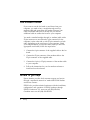
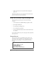
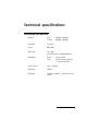
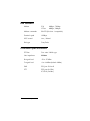
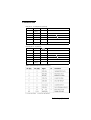
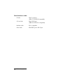
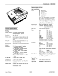
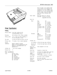
C823301
Fax I/F Board
User’s Manual
Introduction
This EPSON® Fax Interface Board adds standalone plain paper
fax reception to your EPSON laser printer. The Fax Interface
Board is a G3 facsimile receiver and can be connected to any
standard two-wire phone line.
The Fax Interface Board can also serve as a Class 1 Fax modem
connected to a computer’s serial interface if you use the proper
fax software (which is not included in this package).
After you install the board in your printer and connect it to an
appropriate telephone line, you can receive faxes any time the
printer is turned on and is on line, or while it is printing. The
printer cannot receive faxes if it is off line or turned off.
Printers that can use the interface board
The board can be installed in the optional interface slot of these
EPSON printers:
EPLTM-8000 (for this printer, notice the setting on page 6)
ActionLaser II
ActionLaser 1000
ActionLaser 1500
ActionLaser 1600
Introduction 1
Setup
Setting up your fax board is a four-step process:
1.
Set the DIP switches on the board.
2.
Install the board in your printer.
3.
Plug the appropriate cables into the board.
4.
Perform a self test.
Before you install your fax board, you need to make a number
of choices about how your fax board will work. Read the
descriptions below, make your choices, and then proceed with
your setup.
Fax reception modes
This board has three fax reception modes:
2
o
Automatic reception-it starts to receive a fax when the
ring signal is detected.
o
Selective reception-it starts to receive a fax either 15 or
30 seconds after it detects a ring signal (depending on the
setting you select).
o
Manual reception-you have to use software or press the
manual reception button to receive a fax.
Setup
Automatic reception
Select this mode if you use the fax board with a telephone line
that you use exclusively for fax reception.
If you select Automatic reception mode, the board receives
faxes automatically any time fax data is received and the
printer it turned on. If you wish, you can connect a telephone
to the PHONE connector and place calls when the fax board is
not receiving a fax, but you cannot answer any calls.
Selective reception
Use this mode if you want the fax board to share the same line
with a telephone.
In this mode the telephone rings for a short time (15 or 30
seconds, depending on your setting) when a call comes in and
then the board begins fax reception if you do not answer the
telephone. If you answer the phone and it is a fax transmission,
you press the manual reception button and transmission
begins. If it is a voice call and you do not answer the phone,
the caller will hear a fax tone.
You can place telephone calls any time the board is not
receiving a fax.
Setup
3
Manual or software reception
Select this mode if you want to connect the fax board to your
computer and use fax sending and receiving software or if you
use the fax board with a telephone line that you usually use for
voice calls.
In this mode, you receive a fax using your fax software or in
the following manner:
1.
Answer the telephone connected to the fax board.
2.
Push the manual reception button within 20 seconds after
you hear the fax tone signal.
3.
Hang up your telephone when the fax tone stops.
You can make a telephone call or answer the phone any time
the fax board is not receiving fax data.
4
Setup
Once you have decided which fax reception setting you want,
set the DIP switches according to the table below.
This illustration shows the location of the switches; on is up
and off is down.
I
ON
OFF
topview
1
I
I I
Manual Reception
Button
Phone
Line
I
Telephone
I
L
Serial Interface
Fax reception settings
I SWl-1
I
SWl-2
I Functions
OFF
OFF
Automatic reception mode (default)
OFF
ON
Selective reception mode (15 second delay)
ON
OFF
ON
ON
Selective reception mode (30 second delay)
1Manual reception mode
Setup
5
There are three other settings you may want to change:
Paper size
The fax board can use either paper size shown below.
SW 1-3
Functions
OFF
Letter (default)
ON
A4
I
I
Page overflow settings
If the sending fax machine sends an extra-long page, the fax
board can do either of the following:
SW 1-6
1 OFF
ON
I
Functions
I
Print the overflow data to the next sheet (default)
I
Discard the overflow data
Print data transfer speed
The fax board transfers fax data to the printer very quickly.
If the data transfer is too fast for the printer, a SET FULL
PRINT error may occur on your printer. If this error happens
frequently on your printer, reduce the duty percentage using
the following settings. Note that you should always use the
10% setting for the EPL-8000.
Functions
SW 2-1
SW 2-2
OFF
OFF
OFF
ON
120% duty
ON
OFF
110% duty (EPL-8000)
ON
ON
30% duty (default)
5% duty
All other DIP switches must be set to OFF, except switches 1-7,
1-8, and 2-8, which must be set to ON.
6
Setup
I
I
Installing the fax board in your printer
After you have set the DIP switches, install the fax board in
your printer following the instructions in your printer manual.
See the section on installing an optional interface board.
Connecting the board
After you have installed the board, connect the phone cable
included with the board to the connector labeled LINE on the
board. Plug the other end into a standard modular-type
telephone connector (jack). If you wish, you can also plug a
telephone into the connector labeled PHONE.
sideview
Manual Reception
Button
to Phone Line to Telephone
Serial Interface
Performing a self test
After you have installed the fax board in your printer, perform
a self test by following the steps below:
1. While holding down the manual reception button on the
fax board, turn on the printer.
2.
Release the manual reception button when the printer’s
FEED indicator starts blinking.
The printer then prints a two-page self test. This shows that the
board is properly installed and gives you information about the
board and its settings.
setup
7
Fax modem mode
If you want to use the fax board to send faxes from your
computer, you need to buy a straight through serial (or
modem) cable and appropriate fax modem software. One
cable is included with your fax board, but you need an
additional cable to connect the board to your computer.
You need a standard straight through (or modem) cable with a
25-pin connector on one end and a 9-pin connector (for the
computer) on the other end or with 25-pin connectors on both
ends, depending on the serial port of your computer. Check
your computer before you buy the cable. When you have the
appropriate serial cable, follow the steps below:
1.
Connect the 9-pin connector of the supplied cable to the fax
board.
2.
Connect the 25-pin connector of the modem cable to the
25-pin connector of the supplied cable.
3.
Connect the 9-pin (or 25-pin) connector of the modem cable
to your computer.
4.
Follow the instructions for your fax modem software to
install and use the software.
Where to get help
Epson America provides local customer support and service
through a nationwide network of authorized EPSON dealers
and Service Centers.
EPSON also provides technical assistance with the installation,
configuration, and operation of EPSON products through
EPSON Connection. U.S. users can call (800) 922-8911;
Canadian users can call (800) GO-EPSON.
8
Setup
Troubleshooting
When the fax board cannot receive a fax
The fax board has a 300KB buffer that allows it to store fax data
when it can receive but not print. It can store up to 15 pages
depending on the amount of text and graphics on each page.
For example, it uses the buffer when it receives a fax while it is
printing a standard print job sent by your computer.
The fax board cannot, however, receive a fax under the
following conditions:
o
o
o
o
When the buffer is full
When the printer is off line
When the phone line is already in use
When the printer is turned off.
The fax board cannot begin reception if the printer is off line
before the fax data starts arriving, but it can continue reception if
the printer is taken off line after the board begins receiving a
fax.
Printer error
The fax board can receive fax data until the data buffer is full
under the following conditions:
0
o
0
0
0
Paper out
Toner out
Paper size error
Paper jam
Cover open
Troubleshooting 9
o
Other errors that can be corrected without turning the
printer off.
After these printer errors are corrected, the fax board starts to
print the received fax data automatically.
When the fax board stops receiving a fax
The fax board stops receiving fax data in the following
situations:
o
Service request error (SERVICE REQ on printer’s LCD)
o
Fax reception buffer full
o
Fax sender quits sending the fax
o
Loss of phone line connection
o
Protocol mismatched between the fax board and the other
fax machine.
If one of these should occur, all or some part of the received fax
data may be lost.
Wrong printer error
The fax board operates in the EPSON printers listed in the
Introduction. If it is installed in any other printer, it may not
print, it may print garbage, or it may print the following
message:
This card cannot be used in the printer. Pull out the card.
TYPE-B INTERFACE CARD
Ver Fl.xx / Vl.xxA
STATUS CODE xxxxxxxx
SEIKO EPSON CORPORATION
10
Troubleshooting
Limitations
EPL - 8000 users
Set the following DIP switches if the fax board is installed in
the EPL-8000.
SW 2-l ON
SW 2-2 OFF
ActionLaser II users
Set the printer emulation mode for the option interface card to
the LJ-2 (Laser Jet) mode using SelecType. (See your printer
manual for instructions on setting this mode.)
EPSON GL ldentity Card (C826022) users
Set the printer emulation mode from the option interface card
to a mode other than the HP-GL mode using the control panel.
(See your printer manual for instructions on setting the mode.)
PostScript® Card users
Set the printer emulation mode for the option interface card to
a mode other than the AUTO (AES; Auto Emulation Switch)
mode using the control panel. (See your printer manual for
instructions on setting the mode.)
PostScript ID card
EpsonScript Level 2 cartridge
EpsonScript Level 2 board
(C826051)
(C832021)
(C832091)
Troubleshooting 11
Error Codes
Error status report
When an error occurs, the fax board prints a Fax Reception
Error report, which includes an Error Code number. See the
listing below for the meaning of the error code.
Error code listing
1Printer error
I
I
100
I
Printer off-line
101
Paper out
102
Paper jam
103
Toner out
104
I
Cover open
105
Service Request error
106
Paper size error
Fax board error
200
I 201
Received data buffer full
I
203
Communication module error
Hardware error
Communication line error
500
Bad line condition
501
Line noise
502
Abort request from the other fax machine
503
Line on hook
504
No response from the other fax machine
Fax protocol errors
600-603
Other errors
900
12
Troubleshooting
Technical specifications
Facsimile reception
Modem
V.29
V.27ter
Facsimile
T.30 (G3)
Codec
MH, MR
Paper size
A4, Letter
(A4 mode on fax communication)
Resolution
Raster
Feed
NCU control
Auto / Manual
RX buffer
300KB
RX pages
15 pages (constant / standard A4 test
chart)
9600bps, 7200bps
4800bps, 2400bps
8.00 dot/mm
3.85 dot/mm (Normal)
7.70 dot/mm (Fine)
Technical specifications 13
Fax modem
Modem
V.29
V.27ter
Modem commands
EIA-578 (Fax class 1 compatible)
Terminal speed
19200bps
NCU control
Auto / Manual
Dial type
Tone/Pulse
9600bps, 7200bps
4800bps, 2400pbs
Common specifications
14
PTT line
Two wires 3.4kHz type
Line impedance
600ohm
Rx signal level
-15 to -35 dBm
TX signal level
-9 to -16 dBm (default -9dBm)
EMI
FCC part 15 class B
PTT
FCC part 68 (USA)
IC CS-03 (Canada)
Technical specifications
Connectors
LINE (RJ-11: to telephone network)
No.
Signal
1
(N.C.)
2
(N.C.)
3
4
5
(N.C.)
6
(N.C.)
I/O
Comments
I
PTT LINE (-48V / RING)
I
PTT LINE ( EARTH / TIP)
PHONE (RJ-11: to phone)
No.
Signal
1
(N.C.)
2
(N.C.)
3
4
5
(N.C.)
6
(N.C.)
IlO
Comments
0
PTT LINE (-48V / RING)
0
PTT LINE ( EARTH / TIP)
SERIAL (MINI-DIN 9p: RS-232 to HOST PC)
I: to the fax board
0: from the fax board
Technical specifications 15
Serial interface cable
16
PC side
DB-25 connector
(DDK 17 JE-13250-02 compatible)
I/F card side
Mini- DIN 9-pin
(MSK EC-35-9P-C111 compatible)
Modular cable
RJ-11 compatible
Serial cable
Mini-DIN 9-pin to DB 25-pin
Technical specifcations