1
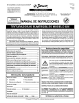
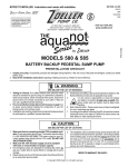
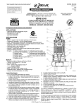
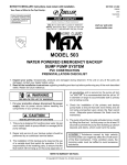
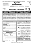
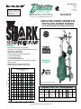
SECTION: 2.50.030
FM1563
1106
Supersedes
0803
Product information presented
here reflects conditions at time
of publication. Consult factory
regarding discrepancies or
inconsistencies.
MAIL TO: P.O. BOX 16347 • Louisville, KY 40256-0347
SHIP TO: 3649 Cane Run Road • Louisville, KY 40211-1961
(502) 778-2731 • 1 (800) 928-PUMP • FAX (502) 774-3624
visit our web site:
www.zoeller.com
SIMPLEX REPLACEMENT GRINDER FOR
POSITIVE DISPLACEMENT GRINDERS
(For Pump Prefix Identification see News & Views 0052)
FEATURES:
FEET
METERS
• Rust Resistant Steel Cover (Epoxy Coated)
• 2 HP, 60 Hz, 1 Ph, 3450 RPM, Automatic Grinder Pump with
Integral Control. (See FM1478)
• Upper and Lower Ball Bearings
• Corrosion resistant powder coated epoxy finish
• 1¼" NPT Galvanized Piping
• 1¼" Cast Iron Check Valve
• 1¼" Rubber Discharge Pipe Seal.
• Grinder Control Float factory set to match pressure collector
system “ON” level
• Adjustable Alarm Float Switch preset at factory
• Maximum operating temperature 130°F (54°C)
WD820/WH820
AUTOMATIC
PUMP PERFORMANCE CURVE
MODEL 820
110
32
100
TOTAL DYNAMIC HEAD
28
24
90
80
70
Product may not be exactly as pictured.
20
60
16
12
SIMPLEX REPLACEMENT GRINDER
50
820 GRINDER • 2 HP, 1¼" N.P.T. • VERTICAL DISCHARGE
Assembly Assembly
Pump
Pump Model
Part Number Weight Part Number Weight
40
30
8
20
4
10
0
5
10
15
20
25
35
30
40
45
50
Volts
Ph
Mode
932-0005 129 lbs.
820-0011
92 lbs. WD820* 230
1
Auto
13.7
932-0006 129 lbs.
820-0005
92 lbs. WH820* 200
1
Auto
15.5
932-0007 130 lbs.
820-0013
93 lbs. WD820
230
1 Auto/Man. 13.7
932-0008 130 lbs.
820-0014
93 lbs. WH820
200
1 Auto/Man. 15.5
10-1195 Adapter kit J-box assembly for pumps w/quick disconnect plug connection.
10-1196 Adapter kit discharge assembly for pumps w/gooseneck discharge.
GALLONS
LITERS
0
40
80
FLOW PER MINUTE
120
160
010440
Amp
* WD & WH grinder pumps are completely automatic with starting controls in pump switch case.
© Copyright 2006 Zoeller Co. All rights reserved.
FIGURE 1 TYPICAL INSTALLATION - WD820 & WH820 MODELS
3.
ELECTRICAL CORDS TO PANEL OR JUNCTION BOX
CORD SEAL
15 3/4" X 1/4" STEEL
EPOXY COATED PUMP PLATE
5/16" 304 STAINLESS STEEL
LIFTING BOLT
4.
3 1/2"
1 1/4" GROMMET SEAL
5.
1 1/4" X 11"
GALVANIZED PIPE
CAST IRON ADAPTERS
1 1/4" FEMALE NPT
CAST IRON CHECK VALVE
1 1/4" X 14"
GALVANIZED PIPE
6.
(FLOAT SWITCHES SHOWN
HERE FOR CLARITY. ACTUAL
ORIENTATION WILL VARY.)
36 1/2"
7.
1 1/4" X 17"
GALVANIZED PIPE
200V-230V, 1PH, 2HP
FULLY AUTOMATIC
GRINDER PUMP
(ALARM, FIELD VERIFIED PER
APPLICATION; FACTORY SET AT 27")
3 1/2"
8.
6 3/4"
ON
16"
OFF
8 3/8"
SK1714
24"
FIGURE 2
9.
FIGURE 3
A
A-B
10.
SK1864A
SK1864B
FIGURE 5 - AUTOMATIC/MANUAL MODELS
FIGURE 4
ADAPTER FITTING
6 CONDUCTOR TRAY CABLE
TE
CK
BLA
EN
WHI
RED
BLUE
11.
GRE
ORA
NGE
B
2 CONDUCTOR
ALARM CORD
SK1864C
BLACK
WHITE
RED
GREEN
WHITE
BLACK
12.
13.
4 CONDUCTOR
PUMP CORD
14.
SK1864D
PREINSTALLATION CHECKLIST
1. Inspect your pump assembly. Occasionally, products are damaged during
shipment. If the unit is damaged, contact your wholesaler before using.
2. Carefully read the literature provided to familiarize yourself with specific
details regarding installation and use. These materials should be retained
for future reference.
3. Check to be sure your power source is capable of handling the voltage requirements of the motor, as indicated on the pump name plate and literature.
4. Make sure the pump electrical supply circuit is equipped with fuses or circuit
breakers of proper capacity. A separate branch circuit is recommended, sized
according to the “National Electrical Code” for the current shown on the pump
name plate and literature.
5. See CAUTIONS & WARNINGS on FM1239: 820 GRINDER INSTALLATION
INSTRUCTIONS.
NOTE: If you do not know the pump-out cycle time, record it from the
closest pump unit with similar head requirements or higher. (See 20
below)
TYPICAL REPLACEMENT INSTALLATION
1. Electrical wiring and enclosures must be in accordance with the “National
Electric Code” and any other applicable state and electrical requirements.
ELECTRICAL PRECAUTION-Before servicing a
2.
pump always shut off the main power breaker - making sure you are
wearing insulated protective sole shoes and not standing in water.
Under flooded conditions, contact your local electrical company or a qualified
licensed electrician for disconnecting electrical service prior to pump removal.
Refer to the original installation/service manual for any precautions that
15.
16.
17.
18.
19.
20.
21.
22.
need to be obeyed, ie: pump may have more than one electrical supply
connection.
If installation is outdoors, locate tank riser and unlock and raise hinged riser
lid. For indoor installations, this step is not required.
After you shut off the power, open electrical enclosure or electrical disconnect
to separate pump power lead, and signal leads. Coil wires and lay them to
the side and keep dry.
Close ball or gate valve in discharge line and then disconnect the quick
disconnect assembly.
Loosen the twelve (12) captive 5/16” bolts that retain the grinder pump
core.
Attach lifting cable or rope to the two (2) pump core eye bolts. Carefully raise
pump core straight up and out of the basin. Set old pump core down and
remove lifting cable.
Prepare your Zoeller grinder pump assembly for installation by removing all
packing materials including the white nylon ties that are holding the alarm
float and pump control float to the suspension pipe and discharge pipe. Do
not remove the large black nylon tie that is securing the control float to the
discharge pipe.
For application with an electrical quick disconnect and a gooseneck discharge
pipe, Zoeller Company adapter kit P/N 10-1196 will simplify installation.
Measure distance from underside of pump plate to gooseneck outlet. See
Figure 2. Record measurement. Place adapter fitting on 1¼” discharge pipe
of the new replacement pump. Measure the distance from the underside of
the replacement plate to the bottom of the internal socket of the adapter fitting.
See Figure 4. Record measurement. Subtract the second measurement from
the first and mark gooseneck with this figure. See Figure 3. Cut old gooseneck
discharge line at this location. Transfer gooseneck pipe to the replacement
grinder and tighten adapter fitting. Place old pump core out of the way.
Verify the correct pump “On” height by measuring the height from the threaded
discharge to the top of the black nylon tie securing the pump control float
(6¾” - See figure 1). Also verify the distance from the control float to the small
nylon tie that is secured to the black nylon tie mentioned above (3½” - See
fig. 1). Adjust if necessary. With tethered as figured, the pump will turn on at
approximately 16”.
Alarm Float Switch is set at factory to turn “On” at 27”. To change the “On”
level, refer to FM0419; Variable Level Float Switch Installation Instructions.
NOTE: Float switches must be positioned so that they will be free of
any object in the tank and the tank walls.
Attach lifting cable or rope to the stainless steel U-bolts on the pump plate.
Place sealing foam with pressure sensitive adhesive on the underside of the
pump plate. Center the sealing foam over the holes around the edge of the
pump plate. Using a pencil or pen, poke holes thru the sealing foam using
the holes in the pump plate as a guide. Clean off pit where the pump plate
sits.
Lower unit into basin being sure to line up the quick disconnect fittings and the
bolt holes. Start all twelve (12) bolts (supplied) with washers (supplied) under
the bolt heads. After all bolts have been started, the bolts can be tightened.
Engage the quick disconnect, tighten if required, and open the ball or gate
valve in discharge pipe.
Change out the UF cord seals in the electrical enclosure with cord seals
supplied to accept cordage.
Thread pump power cord and alarm float switch cord through the cord seals
and into the electrical enclosure. Zoeller Company adapter kit P/N 10-1195
will simplify installations with an electrical quick disconnect. Installation with
electrical quick disconnect fitting will require the following operations. Cut
six conductor cable leading from tank wall directly above the electrical quick
disconnect fitting. Strip outer cord jacket back three (3) inches from end
being sure not to nick individual conductors. Thread the 6 conductor cables
through the largest cord seal and into the junction box. Thread the pump cord
and float switch cord through the remaining cord seals and into junction box.
Using the wire nuts provided, connect the wires per Figure 5.
Connect pump power cord and alarm float switch cord to their respective
terminations.
Check control panel for relay current/power specifications. If too low, change
relays or rewire as required for the amps on the name plate or catalog
sheet.
Replace electrical enclosure cover. Turn main power breaker on.
Fill basin and allow unit to cycle (on-off). Time the pump-out cycle. The cycle
should be at or less than the recorded cycle time.
For outside installations, hinged cover should now be shut and locked.
Installation is now complete.
For future service and repair information refer to FM1239 (820 Installation
Instructions).
© Copyright 2006 Zoeller Co. All rights reserved.