1
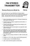
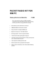
PACKET RADIO KIT FOR
IBM PC
Ramsey Electronics Model No.
P-IBM
Get in the packet fun with your IBM-Compatible
computer and any VHF-FM transceiver! Fast and Easy
to build, you will be running packet this evening!
•
Works with any radio; mobile fixed or hand held
•
FREE BAYCOM TNC software disk included
•
Easy connection to computer’s SERIAL port
•
May also be set up to run “Poor Man’s Packet”
•
No tuning required - Tones are crystal controlled!
•
Transmit time-out timer guard against “hang-ups”
•
Informative manual answers questions on theory, hook-ups and
uses - enhances resale value, too!
•
Ideal companion to Ramsey FX series kits
•
Needs no power source, gets power from computer
•
Add our case for a finished ‘pro’ look. Cases match all Ramsey
products
P-IBM • 1
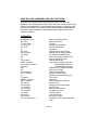
RAMSEY TRANSMITTER KITS
• FM-10 FM Stereo Transmitter
• FM-1,2,3,4 FM Wireless Microphones
• PB-1 Telephone Transmitter
RAMS
LECTR
st
ki
or
ld
Be
RAMSEY HOBBY KITS
• SG-7 Personal Speed Radar
• SS-70 Speech Scrambler
• MM-5 Music Machine
• SP-1 Speakerphone
• MD-3 Microwave Motion Detector
• PH-10 Peak hold Meter
• LC-1 Inductance-Capacitance Meter
E
EY
I CS
ON
RAMSEY RECEIVER KITS
• FR-1 FM Broadcast Receiver
• AR-1 Aircraft Band Receiver
• SR-1 Shortwave Receiver
• AA-7 Active Antenna
• SC-1 Shortwave Converter
tb
u il d e
th
rs in
e
w
RAMSEY AMATEUR RADIO KITS
• FX Series VHF and UHF Transceivers
• HR Series HF All Mode Receivers
• QRP Series HF CW Transmitters
• CW-700 Micro Memory CW Keyer
• PA Series VHF and UHF Power Amplifiers
• Packet Computer Interfaces
• QRP Power Amplifiers
RAMSEY MINI-KITS
Many other kits are available for hobby, school, Scouts and just plain FUN.
New kits are always under development. Write or call for our free Ramsey
catalog.
PACKET RADIO KIT INSTRUCTION MANUAL FOR IBM PC’s
Ramsey Electronics publication No. P-IBM Revision 2.1
First printing: January 1995
COPYRIGHT 1994 by Ramsey Electronics, Inc. 793 Canning Parkway, Victor, New York
14564. All rights reserved. No portion of this publication may be copied or duplicated without the
written permission of Ramsey Electronics, Inc. Printed in the United States of America.
P-IBM • 2
Ramsey Publication No. P-IBM
Price $5.00
KIT ASSEMBLY
AND INSTRUCTION MANUAL FOR
IBM COMPATIBLE
PACKET RADIO
INTERFACE KIT
TABLE OF CONTENTS
Introduction to the P-IBM .................... 4
In Case of Difficulty ............................. 6
Parts List ............................................. 7
PC Board Layout ................................. 8
Kit Building Tips .................................. 9
Modem Parts Installation ..................... 9
Before Hook-up ................................ 14
Initial Procedure ................................ 14
Transceiver Hook-up Diagram .......... 15
Modem to Transceiver Hook-up ........ 17
Modem to Computer Connection........ 18
Printer Port Adaption .......................... 19
Schematic Diagram ............................ 20
Circuit and Device Description ........... 21
Key Functions .................................... 22
Warranty ............................................ 27
RAMSEY ELECTRONICS, INC.
793 Canning Parkway
Victor, New York 14564
Phone (716) 924-4560
Fax (716) 924-4555
P-IBM • 3
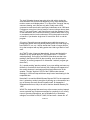
INTRODUCTION TO THE P-IBM PACKET RADIO:
Think for a moment about all those "unusual" computers you saw at the last
hamfest, the gray, blue, black, green or silver ones confidently marked
"Great for Packet" and marked down and down and down to "make offer".
Are those computers and "dumb terminals" REALLY "great for packet"? Sure
they are, as long as they have a working serial port and you have another
piece of equipment called a Terminal Node Controller or "TNC".
After all, the only functions wanted by today's TNC from your computer are
the keyboard and the screen, plus an ability to store files, if that's what you
want. That's because the TNC itself is a microprocessor controlled device,
which means that it IS a computer.
Properly speaking, today's TNC's or "packet data controllers" are a
combination of TWO devices needed for packet operation: the actual TNC
circuit plus a MODEM (MOdulator-DEModulator), a circuit which interfaces
the TNC with the radio. In the early days of packet radio (just a few years
ago!), the TNC and "radio modem" often were two separate pieces of
equipment.
So, if you have a TNC and a PC-compatible computer hooked to your
Ramsey FX VHF transceiver or other radio for packet data operation, you are
actually using TWO computers to do the job of one. Your PC can perform all
the functions of a TNC, by means of user-supported shareware.
Therefore, if you have a PC capable of running packet radio software such
as Baycom or PMP (Poor Man's Packet), all you need is a radio modem
capable of handling today's high data speeds. And that's exactly what the
Ramsey P-IBM Packet Modem is designed to do! Your computer and packet
software team up to serve as a very sophisticated, feature-packed TNC, and
the P-IBM Modem is the high-speed vital hardware connection between your
computer and your transceiver.
In fact, your Packet Modem is a solid and economical investment for your
ham radio station that is very unlikely to become obsolete. Data transmission
modes and protocols are still evolving and improving. These can always be
simulated through software in addition to new or upgraded "magic boxes"
offered by the leading manufacturers of data controllers. Yet, the need for a
reliable radio modem or interface between the computer and transceiver
remains the same.
P-IBM • 4
IMPORTANT SOFTWARE NOTICE
The current version of "BAYCOM" packet communications software is
supplied to you FREE at our expense in keeping with the spirit and
purpose of Shareware. It is not a "part" of the Packet Modem kit and is
not warranted by Ramsey Electronics for any purpose whatsoever.
Ramsey Electronics reserves the right to supply any software of its
choice with the modem kit.
The Hams at Ramsey consider Baycom to be a good program and
encourage you to support the work of the European authors as detailed
on the unmodified shareware distribution diskette which we have given
you.
The product sold and warranted by Ramsey Electronics is solely the PIBM kit for constructing a packet data modem. We will replace any
diskette returned to us as defective, but we cannot provide further
information about using any software beyond what is published in this
instruction book for the modem.
If you have questions or problems with your software, simply use normal
ham channels to get help: local clubs, nets, BBS, or write directly to the
program authors listed in the documentation file on the diskette. Again,
we remind you that the authors are entitled to the nominal fee they
request for the use of their program.
P-IBM • 5
Please read BEFORE constructing your Packet Radio Modem:
IN CASE OF DIFFICULTY:
If you are unsuccessful in achieving packet data radio communication with
your setup, there are a number of details that must be double-checked
VERY thoroughly and honestly:
[ ] Correct assembly of the Ramsey P-IBM Modem
[ ] Correct connection to your transceiver
[ ] Correct connection to your computer
[ ] Correct operation of BOTH computer and transceiver
[ ] Understanding of the software documentation and program
operation
[ ] Understanding of packet radio operation in general
setup/
Unlike a simple receiver or transmitter, or one of our many other fun hobby
kits, your packet modem cannot "do" much of anything by itself. It is simply
PART of a Communications SYSTEM that we rely on YOU to set up and
use.
PLEASE construct your modem with great care, so that you can be
confident that it will be a firm and reliable link in a complex system. We
certainly guarantee the modem kit components and the accuracy of the
design. Beyond that, your modem is only ONE part of a complex
interconnection of digital, analog and RF circuitry governed by user knowhow, which, regretfully, we at Ramsey have no control over whatsoever.
Please understand that there are an infinite variety of actual computer,
software, and transceiver combinations. It would be more cost-effective for
us to NOT produce this kit at all than to set our staff up to deal with all the
possible details of getting your computer, your ham rig and you together on
the air. Therefore, we cannot address ANY questions about the use of your
modem. If you believe that there is a problem with the modem itself, it is
your responsibility to follow all procedures published in this manual and to
study carefully the Ramsey Kit Warranty. All units returned for factory
service are subject to the minimum service fee, even if our tests show that
you did a perfect job of assembling the kit.
We don't enjoy being "hard" about this policy, but we think you do indeed
understand the "why" of it. We like how the British translator of the German
BAYCOM software has put it: "ENJOY Packet Radio, the new playground
for the Radio Amateur".
P-IBM • 6
PARTS SUPPLIED WITH THE P-IBM KIT:
CAPACITORS
[ ] 2 33 picofarad (C6,C9)
[ ] 9 .001 uf [marked .001, 102 or 1nf] (C1,C3,C5,C8,C10,C12,C13,C15,C17)
[ ] 1 .1 uf [marked .1 or 104] (C7)
[ ] 4 4.7 to 10 uf electrolytic (C2,C4,C14,C16)
[ ] 1 220 uf electrolytic capacitor (C11)
FIXED RESISTORS
[ ] 2 100 ohm [brown-black-brown] (R15,R17)
[ ] 2 470 ohm [yellow-purple-brown] (R13,R14)
[ ] 1 2.2K ohm [red-red-red] (R18)
[ ] 1 4.7K ohm [yellow-purple-red] (R5)
[ ] 3 10K ohm [brown-black-orange] (R4,R6,R12)
[ ] 2 15K ohm [brown-green-orange] (R8,R16)
[ ] 1 33K ohm [orange-orange-orange] (R11)
[ ] 4 100K ohm [brown-black-yellow] (R1,R2,R7,R10)
[ ] 1 2.2 megohm [red-red-green] (R3)
SEMICONDUCTORS
[ ] 5 1N914 or 1N4148 diode (D1,D2,D4,D6,D7)
[ ] 2 LED (D3,D5)
[ ] 1 NPN transistor type 2N3904 or similar (Q1)
[ ] 1 Voltage Regulator type 7805 (VR1)
[ ] 1 74HC04 14-pin DIP IC (U1)
[ ] 1 TCM3105 16-pin DIP IC (U2)
[
[
[
[
[
[
OTHER COMPONENTS, HARDWARE
] 1 Ramsey P-IBM printed circuit board
] 1 10K Trimmer potentiometer (R9)
] 1 4.4336 MHz Crystal (Y1)
] 1 PC-mount 5-pin DIN connector (J2)
] 1 PC-mount 9-pin DB9 serial connector (J1)
] 1 Floppy disk, Baycom for IBM
REQUIRED, NOT SUPPLIED
[ ] 1 5-pin DIN plug (male) with cable to match transceiver. Use Radio Shack 422151 for easy Ramsey FX
[ ] 1 Serial computer cable: DB9 male/DB9 female
OPTIONAL:
[ ] Ramsey CIBM case kit
NOTE: optional use of packet software using additional connection to computer
parallel port will require wiring a DB25 connector to PC board points P2,P3,P11,
P15,P18. See instructions on page 15.
P-IBM • 7
PC BOARD LAYOUT:
P-IBM • 8
KIT BUILDING TIPS:
Use a good soldering technique - let your soldering iron tip gently heat the
traces to which you are soldering, heating both wires and pads
simultaneously. Apply the solder on the iron and the pad when the pad is
hot enough to melt the solder. The finished joint should look like a drop of
water on paper, somewhat soaked in.
Mount all electrical parts on the top side of the board provided. This is the
side that has no traces or pads on it.
Electrical part installation - when parts are installed, the part is placed flat to
the board, and the leads are bent on the backside of the board to prevent
the part from falling out before soldering. The part is then soldered securely
to the board, and the remaining lead length is then clipped off.
P-IBM MODEM KIT PARTS INSTALLATION:
We have a twofold "strategy" for the order of the following kit assembly
steps. First, we install parts in physical relationship to each other, so there's
a minimum chance of inserting wires into the wrong holes. Second,
whenever possible, we install in an order that fits our "Learn as you Build"
Kit building philosophy.
FOR EACH PART, OUR WORD "INSTALL" ALWAYS MEANS THESE
STEPS:
1. Pick the CORRECT part value to start with.
2. Insert it into the CORRECT PC board location.
3. ORIENT it correctly, which means: PLEASE follow the PC board drawing
and the written directions for ALL parts where there's a right way and a
wrong way to solder it in. (Diode bands, electrolytic capacitor polarity,
transistor shapes, dotted or notched ends of ICs and so forth.)
4. Don't be afraid of ANY pen-style soldering iron producing enough heat to
damage a part.
5. Trim or "nip" excess wire lengths after soldering.
Now, with that out of the way, let's get building!
[ ] 1a. Examine the DB9 female jack, J1, and press it firmly into its position
P-IBM • 9
at the rear of the board. Before soldering, make certain that it is seated
squarely on the board and the pins are protruding thru the board.
[ ] 1b. Solder all J1 connections, including a generous flow of solder to
secure the outer mechanical mounting pins.
[ ] 2a. Similarly, study the design of J2, the 5-pin DIN jack, which may have
either 5 or 7 pins to solder. Before soldering, make very sure that it is
pressed securely and squarely into the board as far as it can go.
[ ] 2b. Install J2 as per 2a.
[ ] 3. Near J2, install C3, .001 uf (marked .001 or 102).
[ ] 4. Install C15, .001 uf.
[ ] 5. Install C8, .001 uf.
[ ] 6. Install R5, 4.7K [yellow-purple-red].
[ ] 7. Install R15, 100 ohms [brown-black-brown].
NOTE: Save some of the longer wire scraps nipped from resistors and
capacitors. These will be used to form wire jumpers (JMP 1, etc) to be
soldered in just like parts during these construction steps.
[ ] 8. Transistor Q1, NPN type 2N3904 or similar, must be installed with the
flat side facing C3 as clearly shown on the PC board illustration. Press it in
as far as it will reasonably go and solder.
[ ] 9. Install C17, .001 uf (marked .001 or 102).
CONSTRUCTION NOTE 1: The kit uses 5 diodes; each MUST be installed
with the dark banded (cathode) end pointed as shown on the PC board
illustration.
[ ] 10. Install D4 near C17.
CONSTRUCTION NOTE 2: Just as for diodes, electrolytic capacitors MUST
be installed with correct polarity. The (+) side is clearly marked for each
electrolytic on the PC board illustration.
[ ] 11. Install C14, 4.7 or 10 uf.
P-IBM • 10
[ ] 12. Install R17, 100 ohms [brown-black-brown].
[ ] 13. Install C7, .1 uf (marked .1 or 104).
[ ] 14. Install trimmer potentiometer R9. It seats neatly into its board
position near C7 and fits only one way. Solder all three pins.
[ ] 15. Install R6, 10K [brown-black-orange].
[ ] 16. Install C4, 4.7 or 10 uf electrolytic.
[ ] 17. Install R11, 33K [orange-orange-orange].
[ ] 18. Install R8, 15K [brown-green-orange].
[ ] 19. Install jumper wire JMP8. Using a scrap lead from a previously
installed component
CONSTRUCTION NOTE 3: Integrated Circuit U2, type TMC3105, is
designed to be soldered directly to the PC board. No socket is needed. If
you wish to use your own 16-pin DIP socket, use the same care in installing
the socket and inserting the IC chip as you would in directly soldering the
IC.
[ ] 20. Install U2, making sure that the notched end is oriented to the front
of the board as shown on the PC board drawing.
[ ] 21. Install C13, .001 uf (marked .001 or 102).
[ ] 22. Install R16, 15K [brown-green-orange].
[ ] 23. Install jumper wire JMP7.
[ ] 24. Install C6, 33pf.
CONSTRUCTION NOTE 4: Crystal Y1 sets U2's internal oscillator to 4.336
MHz. It is soldered in place just like any other small part. Make sure the
base of the crystal is flush against the PC board and that you do not
confuse its location with C6 or JMP7, already installed, or a hole for JMP4.
[ ] 25. Install crystal Y1.
[ ] 26. Install C9, 33 pf.
P-IBM • 11
[ ] 27. Install C12, .001 uf (marked .001 or 102).
[ ] 28. Install R13, 470 ohms [yellow-purple-brown].
[ ] 29. Install R14, 470 ohms [yellow-purple-brown].
[ ] 30. Install jumper wire JMP4.
[ ] 31. Install R12, 10K [brown-black-orange].
PROGRESS NOTE: If we visualize the PC board divided in half, you have
now installed all parts on U2's half of the board except for the Low and High
data LEDs. Therefore, most of the modem circuitry associated with the
transceiver input and output is completed. The remainder of our work will
bring in the serial port and U1's six inventors.
[ ] 32. Install jumper wire JMP5 near J1.
[ ] 33. Install C10, .001 uf (marked .001 or 102).
[ ] 34. Install R18, 2.2K [red-red-red].
The following diodes and jumper wires may be inserted and soldered as a
single construction sequence. Be sure that the diode cathode bands are
oriented correctly, or there will be no serial communication!
[ ] 35. Install diode D6. See Construction Note #1 regarding polarity.
[ ] 36. Install diode D2.
[ ] 37. Install diode D7.
[ ] 38. Install jumper JMP1.
[ ] 39. Install jumper JMP2.
[ ] 40. Install C1, .001 uf (marked .001 or 102).
[ ] 41. Install C11, the large 220 uf electrolytic capacitor.
[ ] 42. Install C16, 4.7 or 10 uf electrolytic, observe polarity.
[ ] 43. The 7805 voltage regulator VR1 is installed standing straight up with
the bare metal heatsink tab facing C16. Press VR1's 3 stiff pins in as far as
they will reasonably go and solder.
P-IBM • 12
[ ] 44. Install R7, 100K [brown-black-yellow].
[ ] 45. Install C5, .001 uf (marked .001 or 102).
[ ] 46. Install R1, 100K [brown-black-yellow].
[ ] 47. Install R4, 10K [brown-black-orange].
[ ] 48. Install R2, 100K [brown-black-yellow].
[ ] 49. Install C2, 4.7 or 10 uf electrolytic, observe polarity.
[ ] 50. Install jumper wire JMP6.
[ ] 51. Install R10, 100K [brown-black-yellow].
[ ] 52. Install diode D1, orient the banded end correctly.
[ ] 53. Install R3, 2.2 megohms [red-red-green].
[ ] 54. Install wire jumper JMP3.
[ ] 55. Referring back to Construction Note #3 if needed, install U1, the 14pin DIP IC type 74HC04. Make certain that all pins are soldered and that
the notched end is oriented toward JMP3 per the board illustration.
[ ] 56a. Examine the LED indicator diodes, D3,D5. DO NOT cut the leads
before installing. The longer lead is the anode. Leave most of the lead
length above the board so they can be bent later to fit the "bulbs" into the
front panel holes of your Ramsey case or other box.
LED PLACEMENT
D3
D5
[ ] 56b. Install LED
Your best assurance
D3 and D5.
R14
R13
P-IBM • 13
that your new Packet
Modem will WORK is to now REVIEW your construction steps with care and
discipline. This is important, because you'll have many other details to attend to
(computer, transceiver, cables, software) in setting up your packet system.
BEFORE HOOKING UP:
Because you cannot simply turn on your modem and watch it do things until it is
interconnected to your transceiver and computer, please use the following
checklist in reviewing your modem construction work:
[
[
[
[
[
[
[
[
[
[
[
[
[
[
[
] Notched ends of U1 and U2 oriented to the front of the board?
] Flat side of Q1 is oriented to the back side?
] + side of all electrolytic capacitors oriented correctly?
] Metal tab of VR1 is on side toward C16?
] Banded cathode ends of all diodes are as illustrated?
] Check for "solder bridges" or missing connections under:
[ ] J1 [ ] J2 [ ] U1 [ ] U2
] No mix-up of anode and cathode on LEDs D3 and D5?
] No mix-up of 100 ohm, 10K, 1K or 100K resistors?
] No mix-up of R18 (2.2K) and R3 (2.2 megohms)?
] C6 and C9 both 33 picofarads?
] Any untrimmed wires bent back over another connection?
] All jumper wires installed?
] No component leads or jumper mistakenly stretched to P2, P3, P11, P15 or
P18?
] C7 correctly installed as .1 uf?
] Other resistors and capacitors double-checked?
SUGGESTED INITIAL PROCEDURES:
If you are experienced with packet radio and computer/radio interconnections,
you will likely move right along and get your system running. If not, we propose
a step-by-step procedure that will help you ease into the realm of radiocomputer interfacing and gain some confidence as you go along. Here's the
game plan:
First, you'll connect the modem to your VHF transceiver (or receiver) and verify
that the modem indeed can receive (demodulate) data signals. You'll verify this
by tuning the receiver, adjusting the audio and watching the Data High and Low
LED indicators.
Next, you'll spend some time with the packet terminal software, including
practice sessions where you'll "connect up" with yourself without going on the
air. Then, you'll explore the receiving or monitoring function of the system...and
then it will become all up to YOU to get on the air!
P-IBM • 14
SETTING UP P-IBM PACKET AND BAYCOM WITH RAMSEY FXSERIES VHF TRANSCEIVERS:
NOTE: Refer to selected steps as needed for basic start-up with ANY VHF
transceiver.
TYPICAL HOOK-UP DIAGRAM:
+13.8 V D C
GR OU N D
MIKE
PTT
GROUN
SPK
D
R
P-IBM • 15
1. Interconnect FX transceiver and Modem with 5-pin DIN cable such as
Radio Shack 42-2151.
2. Install jumper from EXT AUDIO to SPKR on FX PC board (rather than to
DISC or FSK). See FX Reference Pg. 17)
3. Edit SCC.INI file to install your call sign (MYCALL). If you know what
you need and what you're doing, set other parameters at this time.
Otherwise, use the defaults for now and make changes later.
4. Run PARA.EXE to configure Baycom.
5. Connect serial cable between Modem and your computer.
6. Connect antenna and speaker or speaker/mike to FX.
7. Program FX transceiver to local packet channel. (145.05 MHz, etc.).
8. Start Baycom program.
9. Set FX volume to approximately mid-range.
10. With FX squelch properly set, only the "Low" Data LED on the modem
is on steadily. Background noise will light both LEDs erratically.
11. Packet data signals heard from the speaker should be seen clearly in
the rhythm of both modem LEDs and should appear as data in the
"monitor" frame or window of your Baycom screen.
12. Adjust volume control as needed for the most reliable data reception.
It's up to you to decide when you no longer to have the speaker
connected.
13. The Mike Level trimmer is the only modem adjustment. The correct
level of FM deviation is: +/-4KHz. A basic adjustment can be made
by listening for the "cleanest" sound of your signal in a monitor
receiver.
If you are already experienced with packet operation, you can proceed at
your own pace from this point. If you're a newcomer, replace the antenna
with a dummy load, then study and "play" with the program until you know
what you're doing. If possible, set up another receiver, scanner or HT on the
same frequency, so that you can hear the results of your practice connects
or beacons.
Reminder: The FX Transceiver modulation control (R46) MUST be set for
correct FM deviation, or you will experience problems in both receiving and
transmitting. See FX Assembly Manual and the little story by K4ZRA in the
back of this manual.
P-IBM • 16
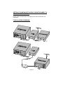
MODEM-TO-TRANSCEIVER HOOKUP:
GENERAL DETAILS: Take the time and care to construct your cable set
carefully, so that this link in your packet system will be as reliable as the
modem itself. Defective cabling or connections are a major cause of both
computer and radio malfunctions. In particular, watch out for:
[ ] Stray wire strands that could cause shorts
[ ] Mixing up mike and speaker lines
[ ] Broken wires
There are three possible approaches for constructing the cable arrangement
that you need:
1. Plain 5-pin DIN plug to which special lines to speaker, mike and PTT are
connected.
2. Pre-assembled 5-pin DIN (one end) cable to which required plugs (RCA,
mini, submini, etc.) are attached.
3. For "vintage" equipment, you might wish to install a 5-pin DIN jack on the
radio's rear chassis, internally wired to the mike, speaker and PTT
lines. Then, use the same type cable as suggested for the Ramsey FX
transceivers to connect the modem to the rig. (Radio Shack 42-2151).
Modem J2 Connections to Transceiver
1. To Microphone
2. Ground
3. PTT line
4. To Speaker
5. +6-12V DC
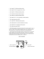
Hook-ups to Hand-held Transceivers
The following schematic diagrams below are for hooking up to a hand-held
radio. There is nothing magical about how these diagrams were designed, we
are simply finding ground and mike audio along with PTT. These hand-held
“key” the transmitter by applying resistance across the mike input to ground.
Resistor R5 in your Packet kit preforms this function.
If you are going to interface your Packet radio kit to another radio which is not
shown here, use the radio’s manual to determine where or how the radio
transmitter is keyed and where or how mike audio is connected. Believe it or
not, it is very simply and is a nice exercise to put your amateur radio “skills” to
work. After all, Ham operators should know how simply electric circuits, we took
a test to prove it and got our ticket!
P-IBM • 17
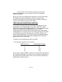
MODEM-TO-COMPUTER CONNECTION (Serial RS232C):
At this stage of the computer evolution, this connection should be s-i-mp-l-e: get a DB9F (female) to DB9M (male) cable from your favorite
computer supplier, hook your Modem to the desired serial port of your
computer...and be done with it.
If you need or want to know more, or if your computer happens to use a
DB25 serial port, please "absorb" and use well the following information
standard for all RS232C connections.
DB9 (9-pin)
1 DCD
2 RD
3 TD
4 DTR
5 GND
6 DSR
7 RTS
8 CTS
9 RI
DB25 (25-pin)
8
3
2*
20*
7*
6
4*
5*
22
P-IBM • 18
The lines marked * are those actually used by the packet modem.
Consult the appendices of your computer manual for more detailed
RS232C information.
NOTE: We cannot over emphasize the importance of verifying that cables
and adapters are wired correctly with no shorts, open lines or wire
reversals. This applies to the off-the-shelf items for which you paid good
money as well as when making your own cables.
"PMP" PARALLEL PRINTER PORT ADAPTION:
It is possible to design a packet terminal program that makes use of the
parallel printer port of IBM-compatible computers. "PMP" (Poor Man's
Packet) is the example immediately familiar to us. The following information
pertains only to preparing the P-IBM modem to work in such a
configuration. Please consult "PMP" documentation for ALL other details.
In this application, a connection from the computer serial port to the modem
is still used, but only as a DC voltage source. In addition, however, you
need to build a special cable to connect the computer's parallel printer port
to the 5 points of the modem circuit clearly designated on the PC board
drawing (P2,P3,P11,P15 and P18).
[ ] Remove or don't install jumpers JMP1 and JMP2.
[ ] The cable goes together "by the numbers":
DB25 Printer Port
2
3
11
15
18
P-IBM Modem PC-Board
P2
P3
P11
P15
P18
Use a male (ie: with pins) DB25 connector if you wish to plug it directly into
your computer's printer port. If you want to run your cable to a switch box or
the printer end of a parallel cable, choose your connector(s) carefully and
identify all pin numbers correctly.
P-IBM • 19
P-IBM MODEM CIRCUIT DESCRIPTION:
The Texas Instruments TCM3105 FSK Modem IC (U2) is the heart and soul of
this proven modem circuit. The functions of the IC pins are designated on the PIBM schematic diagram. In fact, the schematic itself makes most circuit
functions fairly obvious.
U1 is a hex inverter, meaning that it contains six inverters in a single DIP IC
package.
The power input circuitry (VR1,C11,D2,D4,D6,D7 etc.) looks for ANY voltage at
either the RS232C computer connection or pin 5 of the transceiver DIN jack and
provides the regulated +5 VDC required by the modem.
Transmit data from the serial port is converted from RS232C levels (+/-12V) to
TTL levels (+5V and 0V) by inverter U1:a. U2 converts the data to Bell 202
tones (1200 and 2200 Hz), with these frequencies governed by the precision of
Y1. The modulation level of +/- 4 KHz is set by trimmer R9.
Packet AFSK audio tones from the receiver through pin 4 of the DIN connector
are converted by U2 to digital data which is fed to the computer serial port by
U1:C. The Data High and Data Low LED's (D3,D5) are driven by U1:B and
serve the Receive (RXD) line only.
The PTT signal from the computer is converted to a TTL level by U1:D. A "Time
Out" circuit, set for about 40 seconds, is formed by C2,R3,D1 and U1:E. Its
purpose is to unkey the transmitter PTT after that amount of time if the
computer 'locks' up. Q1 is a transceiver switch which will handle virtually any
modern transceiver PTT switching requirement.
Circuit points P2,P3,P11,P15 and P18 are brought out on the PC board to
permit use of the IBM-compatible parallel printer port as may be required by
some packet software programs. The serial TXD and PTT lines must be
disconnected by omitting JMP1 and JMP2. See the detailed discussion of this
application on page 15.
REVIEW:
1. Voltage may be supplied by either computer or transceiver.
2. The modem is designed for Bell 202 tones (1200,2200 Hz) standard for
VHF packet operation.
3. The Mike Level trimmer (R9) should be set for +/-4 KHz FM deviation.
P-IBM • 20
SOME BAYCOM COMMANDS AND KEY FUNCTIONS :
These are summarized for your convenience primarily to illustrate the
capabilities of a software-based TNC. Please check your current version of the
software documentation for further explanations or updates. In publishing this
reference information for the convenience of P-IBM Modem builders, Ramsey
Electronics neither endorses or represents itself as a supplier of this usersupported software.
COMMANDS:
:BADRESS <Call>
:BT <text>
:C <call>[<digi>...]
:CL [1,2 or 3]
:CT <text>
:D
:DC <call>
:DW <number>
:E <name>
:FR
:H
:IP <number>
:LINKT <number>
Over :MAX <Number>
number of
:MH
:MY
:O <command>
:PCA <number>
:Q
:R <name>
:RESPT <number>
:RET <number>
:RP <name>
:TA <number>
:TI <number>
:TQ <number>
:TX <number>
:V <name>
:W <name>
:WP <name>
:X <my><call>[digi>...]
Address for Beacon Entry
Beacon text Entry
Connect
Clearance of a Window
Connect TEXT Entry
Disconnect
Digicall entry of one's choice
Waiting time for empty Channel
File from the Keyboard entry
Frack. Time awaited before POLL
Help (on screen) request
Max Infopoll-length
Link Check if no Data is Carried
MAXFRAME maximum
unacknowledged frames
MHEARD-List (Optional *#<call>)
One's own call sign
DOS-Command Shell
Maximum Frame length
Disconnect if everything arrived
Text File TX
ACK delay
Maximum number of Retries
Binary File TX
Number of terminating Flags
Info TX-Timer
Maximum Time to Quit
TX upper Key Time
Text File record
Text File Receive
Binary File receive
Connection under optional MYCALL
<MY>
P-IBM • 21
KEY FUNCTIONS:
PAGE UP/DN
CTRL-PAGE UP/DN
CTRL-HOME/END
ALT-X
ALT-1
ALT-2
ALT-3
F6/F10
F9
SHIFT-TAB
ESC
INSERT
Page Scrolling
Mon-Window stretch
TX-Window stretch
Program End
Cursor into the TX Window
Cursor into the RX Window
Cursor into the Monitor Window F1...
Port Selection
Cursor Window Exchange
Send Halt
Command Mode (:) Toggle
Insert/Overwrite Mode Switch
A Few Thoughts for Packet Newcomers (and other folks in a big
hurry to get on the air!)
by Dan F. Onley, K4ZRA
Even though I've written this book, use computers daily in my work, have
done a lot of reading about packet radio, and have an Extra class license, I
never before operated packet data radio...and I want to assure you from
direct personal experience that there's a good reason for all suggestions
that sound "preachy" in this documentation.
I wrote most of those common-sense directions BEFORE I decided that I
owed it to you kit-builders and to Ramsey Electronics to take the time to
actually try out "the system"! It does not embarrass me at all to tell you
exactly how it went, because my experiences prove our basic point quite
plainly.
My first conclusion is that you can expect to spend a LOT of time if you try
to get going completely by yourself. I did so intentionally, because it is my
job to make sure you can count on what we publish in this and other
instruction manuals, and I do my best writing from figuring things out for
myself.
My first big chunk of weekend was really wasted until I finally discovered
that my serial cable between the modem and PC was actually the null
modem serial cable I use for dumping files from the laptop to the PC. (A null
modem simply reverses the serial transmit and receive data lines!) That
was just the very beginning of the frustration.
P-IBM • 22
The local 2M packet channel was quite alive with activity during the
entire weekend. But, all that was happening on my setup was that the
monitor screen would display about 1% or less of the "connects" that my
ears were hearing, and that was only after I finally used a DOS
command to make sure that the serial port indeed was set to 1200 baud.
Furthermore, every time I tried a "practice" connect using a dummy load,
the PTT line would "hang", and I would have to exit the program to shut
off the transmitter! And, I could not hear any "packet-racket" from my rig
on a separate monitor receiver whenever I did try the practice connects
or beacons. I just heard a single tone 'til I would use Alt-X to end the
program.
Of course, I figured there was something wrong with the program...or
perhaps the modem was only partially working. After all, I was using my
best 386SX PC, etc, etc. I had to decide that I could no longer afford to
tie up that computer with my failing packet test. Had to get back to "real"
work.
And THAT'S when it improved dramatically. As soon as I hooked the
modem to a very simple laptop PC, the transmit and PTT functions
worked perfectly. So much for the 386SX! (Now what was that I was
reading in the Baycom.DOC file about making sure the serial port's
"interrupt" is correctly jumpered? Or did another "resident" program get
there first?)
So, I started sending "practice packets" to my own callsign and was very
thrilled by it for almost a whole minute! Still, nothing much happened on
the screen whenever I was hearing all that local packet noise in the
speaker. The twin "high-low" LED's of the P-IBM modem danced
teasingly in 1200 baud step with those nasty bursts I was hearing for the
umpteenth time.
Now what? I re-read the British/German Baycom.DOC for the umpteenth
time. I resisted my author's perogitive of phoning up on the weekend to a
guy at Ramsey who really knows his packet stuff. In desperation, I
swapped transceivers, easy to do since I had two identical Ramsey FX146s.
WOW! The local packet folks were busy at the moment, and my laptop's
screen exploded into Christmas messages for everybody in our country,
news of upcoming DXpeditions, and a veritable flurry of worldwide
callsigns, from locals to VE4,KL7,UW3,VK2 and more...almost ALL AT
P-IBM • 23
ONCE!
"Great!" I said to myself, wondering what was so wrong with the FX-146
that I had built so carefully while writing its instruction manual. Now I know
that the P-IBM Packet Modem and the Baycom software surely DO work.
Still, I had to KNOW why the prototype FX-146 worked better than "my
baby".
What can be wrong? There's only 3 receiver adjustments in ham history's
EASIEST- EVER VHF rig to build. I re-checked the trimmer cap in the PLL
and found it to be WWV-perfect. No need to play with the VCO coil,
because I knew the PLL was solidly locked. I tinkered (uselessly) with the
receiver quadrature coil.
So, I dutifully practiced what I always preach and re-checked almost ALL of
FX- 146's parts. I was NOT happy to find them all fine. I really WANTED to
find a mistake in my own FX-146 transceiver. The bad news for me at the
moment was that there were NO mistakes. Then, I remembered a lastminute revision in the FX-146 book requested by Ramsey. That revision
sought better clarity for adjusting the modulation control. The goal is proper
deviation rather than loudest audio. After receiving that revision from
Ramsey engineers, I verified their point for myself with quick tests. But, I
forgot to set the modulation control to its ideal level. In fact, I found it in its
HIGHEST setting, which results in the excessive deviation we don't want.
So, sheepishly, I backed the FX-146's modulation trimmer back down to
proper FM deviation level. Just as quickly, my computer screen became
filled with more worldwide Christmas messages, local news and other
packet stuff.
But, WHY or HOW can a "transmit" adjustment help a "receive" problem?
The answer lies in understanding the VCO: if the modulation is set way too
high, the receiver mode of the radio can be bothered by just enough "stuff"
from the IC microphone amp to interfere with proper data demodulation. It
just takes one "pop" or touch of distortion to demolish a data packet.
Add it all up, and you see exactly what we mean. A guy adds a newly-built
modem and unfamiliar software to his favorite computer and FM
transceiver. Nothing works right. Gradually, he discovers that he was (1)
using the wrong cable; (2) that the serial port in one computer is not set up
properly, and (3) that one transceiver's modulation was not set properly. In
the meantime, the P-IBM and Baycom software were working just fine all
along. And there was really nothing "wrong" with the computer or the radio;
they just weren't set up right by the human in charge.
P-IBM • 24
The Ramsey Kit Warranty
Please read carefully BEFORE calling or writing in about your kit. Most problems can be
solved without contacting the factory.
Notice that this is not a "fine print" warranty. We want you to understand your rights and ours to! All Ramsey
kits will work if assembled properly. The very fact that your kit includes this new manual is your assurance that
a team of knowledgeable people have field-tested several "copies" of this kit straight from the Ramsey
Inventory. If you need help, please read through your manual carefully, all information required to properly
build and test your kit is contained within the pages!
1. DEFECTIVE PARTS: It's always easy to blame a part for a problem in your kit, Before you conclude that a
part may be bad, thoroughly check your work. Today's semiconductors and passive components have
reached incredibly high reliability levels, and its sad to say that our human construction skills have not! But on
rare occasion a sour component can slip through. All our kit parts carry the Ramsey Electronics Warranty that
they are free from defects for a full ninety (90) days from the date of purchase. Defective parts will be
replaced promptly at our expense. If you suspect any part to be defective, please mail it to our factory for
testing and replacement. Please send only the defective part(s), not the entire kit. The part(s) MUST be
returned to us in suitable condition for testing. Please be aware that testing can usually determine if the part
was truly defective or damaged by assembly or usage. Don't be afraid of telling us that you 'blew-it', we're all
human and in most cases, replacement parts are very reasonably priced.
2. MISSING PARTS: Before assuming a part value is incorrect, check the parts listing carefully to see if it is a
critical value such as a specific coil or IC, or whether a RANGE of values is suitable (such as "100 to 500 uF").
Often times, common sense will solve a mysterious missing part problem. If you're missing five 10K ohm
resistors and received five extra 1K resistors, you can pretty much be assured that the '1K ohm' resistors are
actually the 'missing' 10 K parts ("Hum-m-m, I guess the 'red' band really does look orange!") Ramsey
Electronics project kits are packed with pride in the USA. If you believe we packed an incorrect part or omitted
a part clearly indicated in your assembly manual as supplied with the basic kit by Ramsey, please write or call
us with information on the part you need and proof of kit purchase
3. FACTORY REPAIR OF ASSEMBLED KITS:
To qualify for Ramsey Electronics factory repair, kits MUST:
1. NOT be assembled with acid core solder or flux.
2. NOT be modified in any manner.
3. BE returned in fully-assembled form, not partially assembled.
4. BE accompanied by the proper repair fee. No repair will be undertaken until we have received the
MINIMUM repair fee (1 hour labor) of $36.00, or authorization to charge it to your credit card
account.
5. INCLUDE a description of the problem and legible return address. DO NOT send a separate letter; include
all correspondence with the unit. Please do not include your own hardware such as non-Ramsey
cabinets, knobs, cables, external battery packs and the like. Ramsey Electronics, Inc., reserves the
right to refuse repair on ANY item in which we find excessive problems or damage due to
construction methods. To assist customers in such situations, Ramsey Electronics, Inc., reserves
the right to solve their needs on a case-by-case basis.
The repair is $36.00 per hour, regardless of the cost of the kit. Please understand that our technicians are not
volunteers and that set-up, testing, diagnosis, repair and repacking and paperwork can take nearly an hour of
paid employee time on even a simple kit. Of course, if we find that a part was defective in manufacture, there
will be no charge to repair your kit (But please realize that our technicians know the difference between a
defective part and parts burned out or damaged through improper use or assembly).
4. REFUNDS: You are given ten (10) days to examine our products. If you are not satisfied, you may return
your unassembled kit with all the parts and instructions and proof of purchase to the factory for a full refund.
The return package should be packed securely. Insurance is recommended. Please do not cause needless
delays, read all information carefully.
P-IBM • 25
Quick Reference Page Guide
Introduction to the P-IBM ..................... 4
Parts List ............................................. 7
PC Board Layout ................................. 8
Kit Building Tips .................................. 9
Modem Parts Installation ..................... 9
Initial Procedure ................................ 14
Transceiver Hook-up Diagram ........... 15
Modem to Transceiver Hook-up ........ 17
Modem to Computer Connection ........18
Printer Port Adaption ..........................19
Schematic Diagram ............................20
Circuit and Device Description............21
Key Functions ....................................22
Warranty ............................................27
TOTAL SOLDER POINTS
170
ESTIMATED ASSEMBLY
TIME
Beginner ............... 4.9
hrs
Intermediate ......... 2.8
Price: $5.00
Ramsey Publication
No. P-IBM
Assembly and Instruction
manual for:
REQUIRED TOOLS
• Soldering Iron (Radio Shack #RS64-2072)
• Thin Rosin Core Solder (RS64-025)
• Needle Nose Pliers (RS64-1844)
• Small Diagonal Cutters (RS64-1845)
• <OR> Complete Soldering Tool Set
(RS64-2801)
ADDITIONAL SUGGESTED ITEMS
♦ Soldering Iron Holder/Cleaner (RS-642078)
• Holder for PC Board/Parts (RS64-2094)
RAMSEY ELECTRONICS, INC.
793 Canning Parkway
Victor, New York 14564
Phone (716) 924-4560
Fax (716) 924-4555
Printed on recycled paper
P-IBM • 26