1
Px Series
Application Switch
Installation and
Configuration Guide
Extreme Networks, Inc.
3585 Monroe Street
Santa Clara, California 95051
(888) 257-3000
http://www.extremenetworks.com
Published: April 2002
Part number: 100101-00 Rev. 02
©2002 Extreme Networks, Inc. All rights reserved. Extreme Networks and BlackDiamond are
registered trademarks of Extreme Networks, Inc. in the United States and certain other jurisdictions.
ExtremeWare, ExtremeWare Vista, ExtremeWorks, ExtremeAssist, ExtremeAssist1, ExtremeAssist2,
PartnerAssist, Extreme Standby Router Protocol, ESRP, SmartTraps, Alpine, Summit, Summit1,
Summit4, Summit4/FX, Summit7i, Summit24, Summit48, Summit Virtual Chassis, SummitLink,
SummitGbX, SummitPx1, SummitRPS and the Extreme Networks logo are trademarks of Extreme
Networks, Inc., which may be registered or pending registration in certain jurisdictions. The Extreme
Turbodrive logo is a service mark of Extreme Networks, which may be registered or pending
registration in certain jurisdictions. Specifications are subject to change without notice.
NetWare and Novell are registered trademarks of Novell, Inc. Merit is a registered trademark of Merit
Network, Inc. Solaris is a trademark of Sun Microsystems, Inc. F5, BIG/ip, and 3DNS are registered
trademarks of F5 Networks, Inc. see/IT is a trademark of F5 Networks, Inc.
All other registered trademarks, trademarks and service marks are property of their respective owners.
II
Contents
Preface
Introduction
1-vii
Conventions
1-viii
Related Publications
1
2
1-ix
Server Load Balancing Concepts
Purpose of Server Load Balancing
Terms
1-1
1-2
Load Balancing Modes
Layer 4 Load Balancing
Layer 7 Load Balancing and Content Analysis
1-3
1-3
1-4
Port Rewrite
1-6
Getting Started on Load Balancing Configuration
1-6
Installing the SummitPx1 Application Switch
Overview of the SummitPx1 Application Switch
SummitPx1 Front View
SummitPx1 Application Switch Rear View
2-1
2-1
2-3
Determining the Location
2-4
Installing the SummitPx1 Application Switch
Rack Mounting
2-4
2-4
Px Series Application Switch Installation and Configuration Guide
iii
Free-Standing
3
4
iv
2-5
Powering On the SummitPx1
2-5
Setting Up Console Communication
Configuring Switch IP Parameters
Configuring the 10/100 Ethernet Management Port
2-6
2-7
2-8
Installing the PxM Application Switch Module
Installing I/O Modules
3-1
Removing I/O Modules
3-2
Managing the Switch
Using the Command-Line Interface
Abbreviated Syntax and Command Completion
Syntax Symbols
Line-Editing Keys
Specifying Text Values
Command History
Prompt Text
4-2
4-2
4-2
4-3
4-3
4-4
4-4
Configuring Management Access
Changing the Default Passwords
Creating Accounts
4-4
4-5
4-6
Managing the PxM
4-7
Configuring VLANs
4-8
Configuring SNMP
4-9
Configuring DNS Client Services
4-10
Using Secure Shell 2 (SSH2)
Enabling SSH2 for Inbound Switch Access
Using SCP2 from an External SSH2 Client
SSH2 Client Functions on the Switch
4-11
4-12
4-13
4-14
Utilities
Showing CPU Load
Checking Basic Connectivity
Logging
4-15
4-15
4-15
4-16
Px Series Application Switch Installation and Configuration Guide
Configuring a Startup Banner Message
Starting the GlobalPx Content Director Agent
Example Configuration
5
6
4-18
Configuring Servers and Services
Configuring Real Servers
5-1
Configuring Server Groups
5-2
Configuring Virtual Services
Layer 4 Port-based Load Balancing
Layer 7 Virtual Services
Configuring Traffic Tagging
5-3
5-4
5-4
5-5
Configuration Example
5-6
Choosing Policies, Persistence Modes, and NAT
Scheduling Policies
7
4-17
4-17
6-1
Persistence Modes
UDP Flow Persistence
Client IP Persistence Mode
Cookie Persistence Modes
SSL Session Identifier Persistence
6-2
6-3
6-3
6-5
6-13
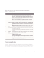
NAT Modes
Full-NAT Mode
Server-only Half-NAT Mode
6-14
6-14
6-15
Configuration Example
6-17
URL Switching
Domain and URL Switching
Domain Switching
URL Switching
7-1
7-2
7-4
Configuring URL Switching
7-4
Creating Domain and URL Switching Rules
Modifying Existing URL Rules and Domains
7-8
7-9
Px Series Application Switch Installation and Configuration Guide
v
Configuration Example
8
9
10
7-9
Configuring Redundancy
Using VRRP with the SummitPx1
Adding and Configuring VRRPs
Using VRRP in Existing Redundant Networks
VRRP Automatic Synchronization
8-1
8-2
8-3
8-4
Configuring Redundancy for the PxM
Using ESRP with the PxM
Configuring the PxM for Multiple VLANs
8-6
8-6
8-7
Configuring a Default Gateway
8-8
Health Checks
Overview
Server Startup Pacing
9-1
9-2
Health Checking Procedure
9-3
Configuring Health Checks
Types of Health Checks
Timers and Counters
9-4
9-4
9-4
Monitoring the Switch
Showing Traffic Statistics
10-1
Showing Configuration Details
Configuration Displays
Status Displays
10-3
10-4
10-5
Managing and Troubleshooting Operation
10-7
Index
Index of Commands
vi
Px Series Application Switch Installation and Configuration Guide
Preface
This preface provides an overview of this guide, describes guide conventions, and lists
other publications that may be useful.
Introduction
This guide provides the required information to configure the Extreme Networks Px
series application switches, SummitPx1TM and PxMTM.
This guide is intended for use by network administrators who are responsible for
installing and setting up network equipment. It assumes a basic working knowledge of:
• Local area networks (LANs)
• Ethernet concepts
• Ethernet switching and bridging concepts
• Routing concepts
• Internet Protocol (IP) concepts, including connection initiation process
• Network Address Translation (NAT)
If the information in the release notes shipped with your switch differs from the
information in this guide, follow the release notes.
Px Series Application Switch Installation and Configuration Guide
vii
Preface
Conventions
Table 1 and Table 2 list conventions that are used throughout this guide.
Table 1: Notice Icons
Icon
Notice Type
Alerts you to...
Note
Important features or instructions.
Caution
Risk of personal injury, system damage, or loss of data.
Warning
Risk of severe personal injury.
Table 2: Text Conventions
Convention
Description
Screen displays
This typeface indicates command syntax, or represents information
as it appears on the screen.
The words “enter”
and “type”
When you see the word “enter” in this guide, you must type
something, and then press the Return or Enter key. Do not press
the Return or Enter key when an instruction simply says “type.”
[Key] names
Key names are written with brackets, such as [Return] or [Esc].
If you must press two or more keys simultaneously, the key names
are linked with a plus sign (+). Example:
Press [Ctrl]+[Alt]+[Del].
Words in italicized type
viii
Italics emphasize a point or denote new terms at the place where
they are defined in the text.
Px Series Application Switch Installation and Configuration Guide
Related Publications
Related Publications
The publications related to this one are:
• ExtremeWare Software User Guide
• Px Series Application Switch Release Notes
Documentation for Extreme products is available on the World Wide Web at the
following location:
• http://www.extremenetworks.com
Px Series Application Switch Installation and Configuration Guide
ix
Preface
x
Px Series Application Switch Installation and Configuration Guide
1
Server Load Balancing Concepts
The Px series application switch marks the next step in server load balancing. Using a
revolutionary hardware design, the Px series application switch is designed to help
website administrators achieve levels of availability and scalability never before
possible.
This chapter contains the following sections:
• Purpose of Server Load Balancing on page 1-1
• Load Balancing Modes on page 1-3
• Port Rewrite on page 1-6
• Getting Started on Load Balancing Configuration on page 1-6
Purpose of Server Load Balancing
An application switch increases website availability by allowing for web servers to fail
(or be shut down for maintenance) without a website outage. It also improves the
response times of the website and increases the traffic-handling capacity of the website
by allowing multiple servers to be used together as a single site.
Px Series Application Switch Installation and Configuration Guide
1-1
The Px series application switch can examine actual user requests, rather than simply
forwarding the requests to the servers. You can use the powerful array of tools provided
by the Px series application switch to scale websites by:
• Creating special purpose servers
• Making better use of web caches
• Allowing movement of web content without extensive re-linking of the site
Terms
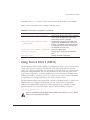
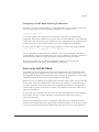
The Px series application switch creates a level of abstraction between the real servers
and the Internet, by configuring a virtual IP (VIP) address and port on the application
switch. The VIP has a globally-reachable public IP address, and corresponds to the DNS
entry for the website. All traffic for the website is sent to the application switch, which
applies policies to decide how to forward the traffic to a real server.
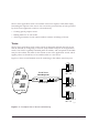
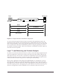
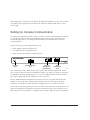
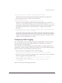
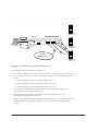
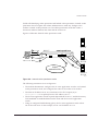
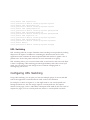
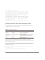
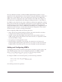
Figure 1-1 shows several Internet users all connecting to the website www.busy.com.
Virtual Server
101.1.35.2
Real Server 1
10.1.1.3
www.busy.com
235.19.10.1
193.16.1.36
64.10.10.100
64.64.6.4
Real Server 2
10.1.1.4
Internet clients
Real Server 3
10.1.1.5
WS_012
Figure 1-1: Conceptual view of server load balancing
1-2
Px Series Application Switch Installation and Configuration Guide
Load Balancing Modes
In this document, the Internet users are referred to as clients, because they are clients of
the application switch. The website, which is actually an address inside the application
switch, is also called a virtual IP address, or VIP. Because the Px series application switch
uses the unique combination of IP address and source port, the VIP is referred to as a
virtual service.
Load Balancing Modes
The Px series application switch can perform packet redirection for load balancing in
two different ways:
• Layer 4 load balancing
• Layer 7 load balancing
Layer 4 Load Balancing
In layer 4 mode, the application switch decides which server should receive a given
user request using server selection policies. It selects a server without looking at the
content of the request. The following server selection policies are supported by the Px
series application switch:
• Round robin
• Weighted round robin
• Least connections
• Weighted least connections
For more information on policies, see Chapter 6.
The application switch can balance almost any traffic using network address translation
(NAT) at layer 4. The application switch rewrites the destination IP address of the
request to point to the real server selected to handle the request, and sets the source IP
address of the request to point to one of the internal IP addresses of the Px series
application switch. When the server responds to the request, the application switch
rewrites the response so that it appears to originate from its VIP address, and forwards
the response to the client.
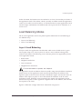
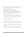
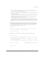
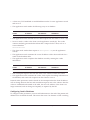
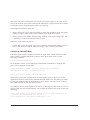
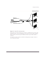
Figure 1-2 illustrates a single client-server transaction using layer 4.
Px Series Application Switch Installation and Configuration Guide
1-3
Client
Real Server
SYN
1
SYN/ACK
ACK
DATA
(http request)
WS_013
Figure 1-2: Single client-server transaction using layer 4
As soon as the first request from the client is received at the application switch, the
application switch uses the server-selection policy configured for the VIP to select the
server and immediately sends out the NAT-ed request to the real server. The client and
server continue the connection establishment protocol using the application switch in
the middle, NAT-ing the traffic. After the connection is established, an HTTP request is
sent and the server responds.
Layer 7 Load Balancing and Content Analysis
To make server-selection decisions based on cookies or the URL being requested by the
client, the application switch must actually look inside the client request. Because this
data request is only sent out after a connection is established, the Px series application
switch must first act as a proxy for the server by acting as the endpoint of the TCP/IP
connection from the client. This process is called layer 7 load balancing.
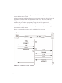
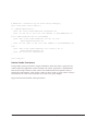
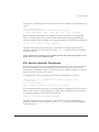
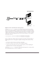
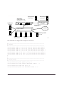
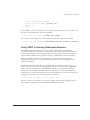
The Px series application switch delays the establishment of a connection to a server
until the first 1500 bytes of actual data (the HTTP request) is received from the client.
The application switch then takes the content being requested, along with the domain to
which the request pertains, and applies policy rules. Based on the outcome of the policy
decision, the application switch establishes a TCP connection with the real server
1-4
Px Series Application Switch Installation and Configuration Guide
Load Balancing Modes
chosen to process the request, using a source IP address that is part of a proxy pool
inside the application switch.
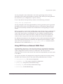
After a connection is established between the application switch and the real server, the
application switch forwards the buffered data to the server. The server sends any
response to the application switch. The application switch translates the IP source
address and port numbers appropriately, along with the TCP sequence and
acknowledgment numbers, and then forwards the data to the real client on the Internet.
Return traffic from the real server does not require content analysis, and is simply
rewritten by the NAT engine.
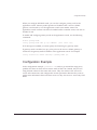
Figure 3 illustrates the sequence used to establish a layer 7 request.
Figure 1-3: Establishing a layer 7 request
Px Series Application Switch Installation and Configuration Guide
1-5
Port Rewrite
When a request is sent by a client to a VIP service, the request contains the well-known
port number for the requested application. For example, the well-known port number
for HTTP is port 80.
You can configure the application switch to rewrite the port, configuring a server group
to use a specific port, other than the well-known port number for the application. Port
rewrite is useful in instances where multiple domains are configured on the same server
(or all servers in the same server group) and each domain has its own server process.
By giving each domain its own port number, each server process can be configured to
listen for requests at its own port.
Getting Started on Load Balancing Configuration
To successfully configure the Px series application switch to perform load balancing
operations, you must consider the following:
• Do you want to use full NAT or server-only NAT mode? For more information on
NAT, see Chapter 6.
• Do you want to use IP address history? For more information on IP address history,
see Chapter 6.
• What server selection policies do you want to use? For more information on
selection policies, see Chapter 6.
• If URL switching is going to be implemented, what DNS domains and patterns will
be used? For more information on URL switching, see Chapter 7.
• If cookies will be used, what cookie mode will be selected, and are the cookies
configured properly on the web servers? For more information on cookies, see
Chapter 6.
After these decisions have been made, follow these steps to configure load balancing:
1 Configure the system IP and related information. For more information, see
Chapter 4.
2 Configure the appropriate global parameters such as NAT mode, proxy-IPs, and
stickiness options. For more information, see Chapter 6.
3 Configure the servers and virtual services:
1-6
Px Series Application Switch Installation and Configuration Guide
Getting Started on Load Balancing Configuration
a Configure the real servers that will be load balanced.
b Create groups of servers, and put the real servers into them.
c
Create a virtual service.
— If the virtual service is layer 4, assign a server group to it.
— If the virtual service is layer 7, create the appropriate domains and pattern-rules,
and assign server groups to the pattern-rules.
For more information, see Chapter 5.
Px Series Application Switch Installation and Configuration Guide
1-7
1-8
Px Series Application Switch Installation and Configuration Guide
2
Installing the SummitPx1
Application Switch
This chapter describes how to install the SummitPx1 configuration of the Px series
application switch. It contains the following sections:
• Overview of the SummitPx1 Application Switch on page 2-1
• Determining the Location on page 2-4
• Installing the SummitPx1 Application Switch on page 2-4
• Setting Up Console Communication on page 2-6
• Powering On the SummitPx1 on page 2-5
Overview of the SummitPx1 Application Switch
SummitPx1 Front View
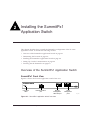
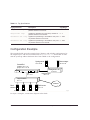
Figure 2-1 shows the Px series application switch front view.
Unit status
LEDs
Network Interface
port
Ethernet
Management
LEDs and port
Serial
Management
ports
SPx1_front
Figure 2-1: SummitPx1 application switch front view
Px Series Application Switch Installation and Configuration Guide
2-1
Table 2-1 describes the LED behavior on the SummitPx1.
Table 2-1: Px series application switch LEDs
LED
Color
Indicates
Link
Green
The 1000Base-T link is operational.
Yellow flashing
There is activity on this link.
Management
Power
Green flashing
■
Slow
The Px series application switch is operating normally.
■
Fast
Power On Self Test (POST) in progress.
Red
The Px series application switch has failed its POST.
Green
The Px series application switch is powered up.
Red
The Px series application switch is indicating a power or
temperature problem.
The front panel of the SummitPx1 has four ports:
• Gigabit Interface Connector (GBIC)
The Network Interface port is a Gigabit Interface Connector (GBIC) used to connect
the application switch to your local network.
• 100BASE-Tx Ethernet Management (RJ-45)
The Ethernet Management port (RJ-45 connector) is a 10/100 Mbps Ethernet
connection used for out-of-band management.
• Console (serial RJ-45)
The console port (serial RJ-45 connector) is used to connect a terminal for local
out-of-band management. The console operates at 9600 baud, 8 data bits, no parity,
one stop bit (8-N-1) with no hardware flow control.
Use the included DB-9 adapter to connect the console to a PC serial port, using a
straight (1-8, 1-8) cable, such as a standard category 3 or category 5 Ethernet cable.
The pinouts for the DB-9 adapter are shown in Table 2-2 on page 2-3.
If you are wiring the console port to a console server, you must use a null modem
cable (1-8, 8-1).
• AUX (serial RJ-45)
The AUX port (RJ-45 connector) has the same pin-outs as the console port. The AUX
port is used for remote out-of-band management.
2-2
Px Series Application Switch Installation and Configuration Guide
Overview of the SummitPx1 Application Switch
Table 2-2: DB-9 Adapter Pinouts
TO: DB-9
FROM: RJ45
SHELL
Signal Description
Pin 6
Pin 1
DSR
Pin 8
Pin 2
CTS
Pin 2
Pin 3
RD
Pin 5
Pin 4
SG
NC
Pin 5
--
Pin 3
Pin 6
TD
Pin 7
Pin 7
RTS
Pin 4
Pin 8
DTR
For more information on connecting and configuring these ports, see “Setting Up
Console Communication” on page 2-6.
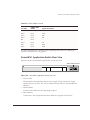
SummitPx1 Application Switch Rear View
Figure 2-2 shows the SummitPx1 application switch rear view.
Power socket and fuse
WS_010
Figure 2-2: SummitPx1 application switch rear view
• Power Socket
The SummitPx1 automatically adjusts to the supply voltage. The power supply
operates down to 90 VAC. The fuse is suitable for both 110 VAC and 220-240 VAC
operation.
• Serial Number
Use the serial number for fault-reporting purposes.
• MAC Address
A label shows the unique Ethernet MAC addresses assigned to this device.
Px Series Application Switch Installation and Configuration Guide
2-3
Determining the Location
The SummitPx1 is suited for use in the office, where it can be free-standing or mounted
in a standard 19-inch equipment rack. Alternatively, the device can be rack-mounted in
a wiring closet or equipment room. Two mounting brackets are supplied with the
device.
When deciding where to install the SummitPx1, ensure that:
• The unit is accessible and cables can be connected easily.
• Water or moisture cannot enter the case of the unit.
• Air-flow around the unit and through the vents in the side of the case is not
restricted. You should provide a minimum of 25mm (1-inch) clearance.
• No objects are placed on top of the unit.
• Units are not stacked more than four high if the switch is free-standing.
Installing the SummitPx1 Application Switch
The application switch can be mounted in a rack or placed free-standing on a tabletop.
Rack Mounting
Caution: The rack mount kits must not be used to suspend the switch from
under a table or desk, or to attach to a wall.
To rack mount the application switch, follow these steps:
1 Place the device the right way up on a hard, flat surface, with the front facing you.
2 Remove the existing screws from the sides of the chassis and retain for step 4.
3 Locate a mounting bracket over the mounting holes on one side of the unit.
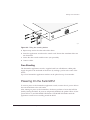
4 Insert the screws and fully tighten with a suitable screwdriver, as shown in
Figure 2-3.
2-4
Px Series Application Switch Installation and Configuration Guide
Powering On the SummitPx1
WS_011
Figure 2-3: Fitting the mounting bracket
5 Repeat steps 2-4 for the other side of the device.
6 Insert the application switch into the 19-inch rack. Ensure that ventilation holes are
not obstructed.
7 Secure the device with suitable screws (not provided).
8 Connect cables.
Free-Standing
The SummitPx1 application switch is supplied with four self-adhesive rubber pads.
Apply the pads to the underside of the device by sticking a pad at each corner of the
device.
Up to four SummitPx1 application switches can be placed on top of one another.
Powering On the SummitPx1
To turn on power to the SummitPx1 application switch, connect the AC power cable to
the switch and then to the wall outlet.
After turning on power to the SummitPx1, the device performs a Power On Self-Test
(POST). During the POST, all ports are temporarily disabled, the packet LED is off, the
power LED is on, and the MGMT LED flashes. The MGMT LED flashes until the
application switch has successfully passed the POST.
Px Series Application Switch Installation and Configuration Guide
2-5
If the application switch passes the POST, the MGMT LED blinks at a slow rate (1 blink
per second). If the application switch fails the POST, the MGMT LED shows a solid
yellow light.
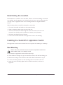
Setting Up Console Communication
To manage the application switch locally, you must connect to the management console
to configure the switch’s Ethernet management port using a serial connection. This
section describes how to to configure the SummitPx1 for communication with the
console interface.
There are four ports on the application switch:
• GBIC 1000bT network interface port
• 10/100BT Ethernet management port
• Serial console and modem management ports
Unit status
LEDs
Network Interface
port
Ethernet
Management
LEDs and port
Serial
Management
ports
SPx1_front
Any workstation with a Telnet facility can communicate with the application switch
over a TCP/IP network. Telnet is enabled by default. Use Telnet to connect to either the
10/100 Mbps Ethernet management port, or to the Gigabit Ethernet network interface
port, after configuring their IP addresses via the serial port.
The 10/100BT Ethernet management port allows the CPU to upload and download
images on a network that is seperate from the data network. This allows the data
network to be outside a firewall while the management port is inside the firewall.
You use the serial management ports for your initial communication with the device, in
order to configure the management and network interface ports. The serial ports use a
RJ45 connector. The SummitPx1 is supplied with an RJ45-to-DB9 converter and ethernet
2-6
Px Series Application Switch Installation and Configuration Guide
Setting Up Console Communication
cable with which to connect most PCs to this port. The console port settings are as
follows:
Baud rate
9600
Data bits
8
Stop bit
1
Parity
None
Flow control
None
Each interface has a unique IP address. Before you can start a Telnet session, you must
set up the IP parameters of the port you will use for management, as described in the
following sections. To open the Telnet session, you specify the IP address of the port.
For information on how to do this, refer to the documentation for your Telnet facility.
After the connection is established, you will see the command-line interface prompt and
can begin configuring the device.
Configuring Switch IP Parameters
To manage the application switch by way of a Telnet connection to the Gigabit Ethernet
port, you must first configure the switch IP parameters. To manually configure the IP
settings, follow these steps:
1 Connect a terminal or workstation running terminal-emulation software to the serial
management (console) port. See “Setting Up Console Communication” on page 2-6.
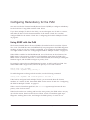
2 Configure the system IP address and default gateway. The following example sets
the address for the Gigabit Ethernet interface:
SummitPx1:4 # config system-ip 64.1.1.10 / 24 vlan 123
SummitPx1:5 # config default-gateway 64.1.1.1
The vlan argument is optional for the SummitPx1, but required for the PxM. See
“Managing the PxM” on page 4-7, and “Configuring VLANs” on page 4-8.
3 Enable the Gigabit port, commit changes, and save your configuration changes to
flash memory, so that they are in effect after the next reboot.
SummitPx1:8 # enable port gigabit
SummitPx1:11 # build
SummitPx1:17 # save
Do you want to save to the primary configuration database (Y/N) ? y
Erasing Flash *
Px Series Application Switch Installation and Configuration Guide
2-7
Writing data to Flash
Done
4 When you are finished using the facility, log out of the application switch.
You can now access the Gigabit Ethernet port directly via Telnet.
Configuring the 10/100 Ethernet Management Port
The 10/100BT Ethernet management port provides dedicated remote access to the
application switch using TCP/IP. It supports Telnet using the command-line interface.
The 10/100BT port is designed to be used as an out-of-band management port only. It does
not function as a load balancing port.
To use the management interface, you must assign it an IP address and subnetwork
mask, using the following command:
config mgmt ip <ipaddress> / <netmask bit length>
The 10/100BT port has a separate routing table. By default, no routes are installed in the
routing table. You must explicitly configure routes. After the IP address has been
configured, install a route for the network, using the following command:
config mgmt iproute dest-ip <ipaddress> gateway <ipaddress>
You can add additional routes, as needed.
The configuration of management port information is executed immediately. You
do not need to use the build command.
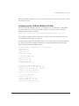
The following example configures an IP address and installs two network routes:
station1:4 # config mgmt ipaddress 10.10.10.2 / 24
station1:5 # config mgmt iproute dest-ip 10.10.10.0 gateway 10.10.10.1
station1:6 # config mgmt iproute dest-ip 10.10.11.0 gateway 10.10.10.1
2-8
Px Series Application Switch Installation and Configuration Guide
3
Installing the PxM Application
Switch Module
The PxM configuration of the Px series application switch is a BlackDiamond module.
The configuration information and specifications for the BlackDiamond I/O modules
are described in detail in the Extreme Networks Consolidated Hardware Guide, as well as
the module installation and removal procedures. For convenience, the information on
installing and removing modules is repeated here.
To manage the application switch locally, you must connect a management console to
the switch’s Ethernet management port using a serial connection. Do this in the same
way as for the SummitPx1; see “Setting Up Console Communication” on page 2-6.
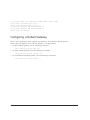
This chapter contains the following sections:
• Installing I/O Modules on page 3-1
• Removing I/O Modules on page 3-2
Installing I/O Modules
You can insert I/O modules at any time, without causing disruption of network
services.
To install an I/O module:
1 Select a slot for the module:
• Slots numbered 1 through 16 in the BlackDiamond 6816
• Slots numbered 1 through 8 in the BlackDiamond 6808
Px Series Application Switch Installation and Configuration Guide
3-1
Caution: You can install I/O modules only in slots 1 through 16 in the
BlackDiamond 6816 or slots 1 through 8 in the BlackDiamond 6808. I/O modules
do not fit in slots A, B, C, or D. Forceful insertion can damage the I/O module.
2 Attach the ESD strap that is provided to your wrist and connect the metal end to the
ground receptacle that is located on the top-left corner of the switch front panel.
3 For the BlackDiamond 6816, ensure that the module is horizontal with the module
name to the left and that the ejector/injector handles are extended.
For the BlackDiamond 6808, ensure that the module is vertical with the module
name at the top and that the ejector/injector handles are extended.
4 Slide the module into the appropriate slot of the chassis (slots 1 through 16 in the
BlackDiamond 6816 or slots 1 through 8 in the BlackDiamond 6808), until it makes
contact with the backplane.
As the module begins to seat in the chassis, the ejector/injector handles begin to
close.
5 To close the ejector/injector handles, use both hands simultaneously to push the
handles toward the center of the module.
6 To secure the module, tighten the two screws using a #1 Phillips screwdriver.
Note: Tighten the screws before inserting additional modules. Otherwise, you
might unseat modules that you have not secured.
7 Repeat this procedure for additional modules, if applicable.
8 Leave the ESD strap permanently connected to the chassis, so that it is always
available when you need to handle ESD-sensitive components.
Removing I/O Modules
All BlackDiamond 6800 series modules (MSM64i and I/O modules) are hot-swappable.
You do not need to power off the system to remove a module.
To remove an I/O module:
1 Attach the ESD strap that is provided to your wrist and connect the metal end to the
ground receptacle that is located on the top-left corner of the switch front panel.
2 Use a #1 Phillips screwdriver to unscrew the two captive screws.
3-2
Px Series Application Switch Installation and Configuration Guide
Removing I/O Modules
3 Simultaneously rotate the ejector/injector handles outward to disengage the module
from the backplane.
4 Slide the module out of the chassis.
5 If you are not going to install a replacement I/O module, cover the slot with a blank
faceplate. Otherwise, follow the I/O module installation procedure above.
6 Repeat this procedure for additional modules, if applicable.
7 Leave the ESD strap permanently connected to the chassis, so that it is always
available when you need to handle ESD-sensitive components.
Px Series Application Switch Installation and Configuration Guide
3-3
3-4
Px Series Application Switch Installation and Configuration Guide
4
Managing the Switch
This chapter covers the following topics:
• Using the Command-Line Interface page 4-2
• Configuring Management Access on page 4-4
• Managing the PxM on page 4-7
• Configuring VLANs on page 4-8
• Configuring SNMP on page 4-9
• Configuring DNS Client Services on page 4-10
• Utilities on page 4-15
• Example Configuration on page 4-18
Px Series Application Switch Installation and Configuration Guide
4-1
Using the Command-Line Interface
To use the command-line interface:
1 Enter the command name. You can use abbreviated syntax; see below.
2 If the command includes a parameter, enter the parameter name and value.
The value specifies how you want the parameter to be set. Values can be numbers,
strings, or addresses, depending on the parameter.
3 After entering the complete command, press [Return].
Most commands are not executed immediately, but are deferred until you issue the
build command. Exceptions are noted when the commands are described in this
manual.
Abbreviated Syntax and Command Completion
Abbreviated syntax is the shortest unambiguous abbreviation of a command or
parameter. Typically, this is the first three letters of the command.
The Px series application switch provides command completion by way of the [Tab]
key. If you enter a command using the abbreviated syntax, pressing the [Tab] key
displays a list of available options, and places the cursor at the end of the command.
The command-line interface also has a syntax helper that provides assistance if you
have entered an incorrect command.
Syntax Symbols
In describing command syntax, this manual uses symbols as described in Table 4-1. The
symbols explain how to enter the command, and you do not type them as part of the
command itself.
Table 4-1: Command Syntax Symbols
Symbol
Description
angle brackets < >
Enclose a variable or value. You must specify the variable or value. Do
not type the angle brackets.
square brackets [ ]
Enclose a required value or list of required arguments. One or more
values or arguments can be specified. Do not type the square brackets.
4-2
Px Series Application Switch Installation and Configuration Guide
Using the Command-Line Interface
Table 4-1: Command Syntax Symbols (continued)
Symbol
Description
vertical bar |
Separates mutually exclusive items in a list, one of which must be
entered. Do not type the vertical bar.
braces { }
Enclose an optional value or a list of optional arguments. One or more
values or arguments can be specified. Do not type the braces.
Line-Editing Keys
Table 4-2 describes the line-editing keys available when using the command-line
interface.
Table 4-2: Line-Editing Keys
Key(s)
Description
Backspace
Deletes character to left of cursor and shifts remainder of line to left.
Delete or [Ctrl] + D
Deletes character under cursor and shifts remainder of line to left.
[Ctrl] + K
Deletes characters from under cursor to end of line.
Insert
Toggles on and off. When toggled on, inserts text and shifts previous
text to right.
Left Arrow
Moves cursor to left.
Right Arrow
Moves cursor to right.
Home or [Ctrl] + A
Moves cursor to first character in line.
End or [Ctrl] + E
Moves cursor to last character in line.
[Ctrl] + L
Clears screen and movers cursor to beginning of line.
[Ctrl] + P or
Up Arrow
Displays previous command in command history buffer and places
cursor at end of command.
[Ctrl] + N or
Down Arrow
Displays next command in command history buffer and places cursor at
end of command.
[Ctrl] + U
Clears all characters typed from cursor to beginning of line.
[Ctrl] + W
Deletes previous word.
Specifying Text Values
When specifying a text values, such as health check objects, return strings, and URL
patterns, it is recommended that you always use double quotes to delimit the text
Px Series Application Switch Installation and Configuration Guide
4-3
value. You must use quotes if the text value includes any non-alphanumeric characters,
such as spaces, dashes, or dots.
Command History
The Px series application switch keeps a history of the last 49 commands you entered.
To display a list of the most recent commands, enter:
history
Prompt Text
The prompt text is taken from the SNMP sysname setting. For more information, see
”Configuring SNMP” on page 4-9.
The number that follows the colon indicates the sequential line/command number. If an
asterisk (*) appears in front of the command-line prompt, it indicates that you have
outstanding configuration changes that have not been saved. For example:
* SummitPx1:19#
The prompt ends with > if you are logged in with user-level privileges, and with # if
you are logged in with administrative privileges. For more information, see
“Configuring Management Access” on page 4-4.
Configuring Management Access
The software supports two levels of management:
• User
A user-level account has viewing access to all manageable parameters except the
user account database and the SNMP community strings.
A user-level account can use the ping command to test device reachability, and
change the password assigned to the account name. If you have logged on with user
capabilities, the command-line prompt ends with a (>) sign. For example:
SummitPx1:2>
4-4
Px Series Application Switch Installation and Configuration Guide
Configuring Management Access
• Administrator
An administrator-level account can view and change all switch parameters. It can
also add and delete users, and change the password associated with any account
name. The administrator can disconnect a management session that has been
established by way of a Telnet connection. If this happens, the user logged on by
way of the Telnet connection is notified that the session has been terminated.
If you have logged on with administrator capabilities, the command-line prompt
ends with a (#) sign. For example:
SummitPx1:18#
Changing the Default Passwords
The switch is automatically configured with one account at each level, with the names
user and admin. By default, these accounts do not have passwords assigned to them. To
add a password to the default admin account, follow these steps:
1 Log in to the switch using the name admin.
2 At the password prompt, press [Return].
3 Add a default password by entering the following:
config account admin
—or—
config account user
4 Enter the new password at the prompt. Passwords can have up to 32 characters, and
are case-sensitive.
5 Re-enter the new password at the prompt.
If you forget your password while logged out of the command-line interface, contact
your local technical support representative, who will advise on your next course of
action.
Px Series Application Switch Installation and Configuration Guide
4-5
Creating Accounts
The application switch can have a total of 16 management accounts. You can use the
default accounts (admin and user), or you can create additional accounts with new
names and passwords. To create a new account, follow these steps:
1 Log in to the switch as admin.
2 At the password prompt, press [Return], or enter the password that you have
configured for the admin account.
3 Add a new account by using the following command:
create account [admin | user] <username>
User names are case-sensitive.
4 Enter the password at the prompt. Passwords can have up to 32 characters, and are
case-sensitive.
5 Re-enter the password at the prompt.
Modifying Accounts
To change the password of an account other than your own, you must have
administrator privileges. Use the following command to modify an account:
config account <username>
Enter and confirm the new password at the prompts.
Viewing Accounts
To view the accounts that have been created, you must have administrator privileges.
Use the following command to see the accounts:
show accounts
Deleting an Account
To delete an account, you must have administrator privileges. Use the following
command to delete an account:
delete account <username>
The account name admin cannot be deleted.
4-6
Px Series Application Switch Installation and Configuration Guide
Managing the PxM
Managing the PxM
You can manage the PxM in any of the following ways:
• Using the connect command in the BlackDiamond.
• Using the serial port (useful for debugging).
• Using the 101100 port (for out-of-band management).
VLANs are always enabled on the PxM. A configuration that does not contain VLAN
information will fail to build and report syntax errors for the PxM. You must configure
a VLAN on the MSM before you configure it on the PxM. See “Configuring VLANs” on
page 4-8.
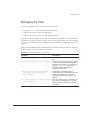
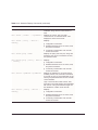
Table 4-3 shows BlackDiamond ExtremeWare commands that apply solely to the PxM,
or have specific syntax that applies to the PxM:
Table 4-3: Commands Unique to the PxM
Command
Description
connect slot <number>
Creates a PxM session for the specified
slot.
show pxm [interfaces] [slot <number>] Displays data on the PxM in the specified
slot. If no slot is specified, displays data on
all PxMs in the chassis. If you specify the
optional interfaces argument, the
command updates the statistical
information in real time.
download [image|config] <hostname>
<filename> [primary|secondary]
[slot <number>]
Downloads the specified image or
configuration from the specified host to the
PxM in the specified slot. If no slot is
specified, downloads to all PxMs in the
chassis.
use [image|config] [primary|secondary] Sets the default image or configuration for
the PxM in the specified slot. If no slot is
[slot <number>]
specified, sets the default for all PxMs in
the chassis.
Px Series Application Switch Installation and Configuration Guide
4-7
Some commands do not work at all if the PxM is not booted and ready. It can take more
than two minutes to boot. To verify from the MSM that a PxM is booted, use the
command show pxm.
• If the PxM is booted and ready, the card state is displayed as operational.
• If the PxM for a slot has not been booted or is not ready, the command shows no
status for that slot.
Configuring VLANs
The Px series application switch supports up to 4,096 VLANs. VIPs and servers can be
on any VLAN, but the system IP and proxy IPs must reside in the same VLAN. For all
but the main system VLAN, the application switch learns VLANs as traffic is received
for the VIP or real server that resides on a VLAN.
The application switch identifies VLANs with 802.1q VLAN ID numbers rather than
names. You must configure the VLAN number on the system IP address.
For the SummitPx1, before configuring VLANs for the application switch itself, you
must enable VLAN tagging on the switch port connected to the application switch, and
add the VLANs you need to the port, using the manufacturer’s instructions. For the
PxM, VLANs are automatically enabled between the PxM and the connected
BlackDiamond switch.
To configure VLANs for the application switch:
• Enable VLANs on the application switch, using the following command:
enable vlan
• Configure the system VLAN on the application switch, using the following
commands:
config system-ip <ipaddress> / <netmask> vlan <vlan_tag_number>
build
The SummitPx1 learns VLAN tags as traffic enters on the tagged port. On the PxM,
however, you must configure a VLAN tag for each virtual service. (This is optional for
the SummitPx1, where you can assign a specific VLAN tag to a virtual service for use
with VRRP failover; see Chapter 8.)
4-8
Px Series Application Switch Installation and Configuration Guide
Configuring SNMP
To assign a VLAN tag to a service, use the following command:
config service vip <ip address> vlan <vlan_tag_number> port <number>
protocol [tcp|udp] [L4|L7] server-group-name <label>
Configuring SNMP
Any network manager running the Simple Network Management Protocol (SNMP) can
manage the switch, provided that the management information base (MIB) is installed
correctly on the management station. Each network manager provides its own user
interface to the management facilities. If you are not familiar with SNMP management,
refer to the following publication:
The Simple Book by Marshall T. Rose
ISBN 0-13-8121611-9
Published by Prentice Hall
Changes to SNMP settings are executed immediately, and do not require the
build command.
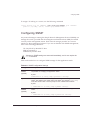
Table 4-4 describes how to configure SNMP settings for the application switch.
Table 4-4: SNMP Configuration Settings
Setting
Description
System
contact
(optional)
The system contact is a text field that identifies the person or persons
responsible for managing the application switch.
Syntax:
SummitPx1:15 # config snmp sysContact <string>
System name
The system name is the name that you have assigned to this application
switch. The default is the model name of the switch (for example, SummitPx1).
This value is also used to set the prompt for the command-line interface.
Syntax:
* SummitPx1:13 # config snmp sysName <string>
System
location
(optional)
Use the system location field to enter an optional location for this application
switch.
Syntax:
* SummitPx1:14 # config snmp sysLocation <string>
Px Series Application Switch Installation and Configuration Guide
4-9
Table 4-4: SNMP Configuration Settings
Setting
Description
Community
strings
The community strings allow a simple method of authentication between the
application switch and the remote Network Manager. There are two types of
community strings on the application switch.
■
■
Read community strings provide read-only access to the application switch.
The default read-only community string is public.
Read-write community strings provide read and write access to the
application switch. The default read-write community string is private.
A total of eight community strings can be configured on the application switch.
The community string for all authorized trap receivers must be configured on
the application switch for the trap receiver to receive.
Syntax:
* SummitPx1:16 # config snmp add community readonly
<string>
* SummitPx1:17 # config snmp add community readwrite
<string>
Authorized
trap receivers
An authorized trap receiver can be one or more network management stations
on your network. The application switch sends SNMP traps to all trap
receivers. You can have a maximum of 16 trap receivers configured for each
application switch.
Syntax:
* SummitPx1:17 #config snmp add trapreceiver <ipaddress>
Optionally, you can change the IP port to which traps are sent if the server is
running the syslog process on a non-standard port:
* SummitPx1:17 #config snmp add trapreceiver <ipaddress>
community <string> port <number>
Configuring DNS Client Services
The Domain Name Service (DNS) client in ExtremeWare augments the following
commands to allow them to accept either IP addresses or host names:
•
telnet
•
download [configuration | image]
•
upload configuration
•
ping
•
traceroute
4-10
Px Series Application Switch Installation and Configuration Guide
Using Secure Shell 2 (SSH2)
In addition, the nslookup utility can be used to return the IP address of a hostname.
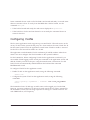
Table 4-5 lists commands used to configure the DNS client.
Table 4-5: DNS Client Configuration Commands
Command
Description
config dns-client add <ipaddress>
Adds a DNS name server(s) to the available
server list for the DNS client. Up to three
name servers can be configured.
config dns-client default-domain
<domain_name>
Configures the domain that the DNS client
uses if a fully qualified domain name is not
entered. For example, if the default domain
is configured to be foo.com, executing ping
bar searches for bar.foo.com.
config dns-client delete <ipaddress>
Removes a DNS server.
nslookup <hostname>
Displays the IP address of the requested
host.
show dns-client
Displays the DNS configuration.
Using Secure Shell 2 (SSH2)
The ExtremeWare Secure Shell 2 (SSH2) switch application allows you to encrypt Telnet
session data between a network administrator using SSH2 client software and the
switch, or to send encrypted data from the switch to an SSH2 client on a remote system.
Image and configuration files may also be transferred to the switch using the Secure
Copy Protocol 2 (SCP2). A command enables the switch to function as an SSH2 client,
sending commands to a remote system via an SSH2 session. There are also commands
to copy image and configuration files to the switch using the SCP2.
The ExtremeWare SSH2 switch application is based on the Data Fellows™ SSH2 server
implementation. It is highly recommended that you use the F-Secure SSH client
products from Data Fellows corporation. These applications are available for most
operating systems. For more information, refer to the Data Fellows website at:
http://www.datafellows.com
SSH2 is compatible with the Data Fellows SSH2 client version 2.0.12 or above.
SSH2 is not compatible with SSH1.
Px Series Application Switch Installation and Configuration Guide
4-11
The ExtremeWare SSH2 switch application also works with SSH2 client and server
(version 2.x or later) from SSH Communication Security, and the free SSH2 and SCP2
implementation (version 2.5 or later) from OpenSSH. The SFTP file transfer protocol is
required for file transfer using SCP2.
Enabling SSH2 for Inbound Switch Access
Because SSH2 is currently under U.S. export restrictions, you must first obtain a
security-enabled version of the ExtremeWare software from Extreme Networks before
you can enable SSH2. The procedure for obtaining a security-enabled version of the
ExtremeWare software is described in the ExtremeWare Software User Guide.
You must enable SSH2 on the switch before you can connect to it using an external
SSH2 client. Enabling SSH2 involves two steps:
• Enabling SSH2 access, which may include specifying a list of clients that can access
the switch, and specifying a TCP port to be used for communication. By default, if
you have a security license, SSH2 is enabled using TCP port 22, with no restrictions
on client access.
• Generating or specifying an authentication key for the SSH2 session.
To enable SSH2, use the following command:
enable ssh2 {access-profile [<access_profile> | none] {port
<tcp_port_number>}}
You can specify a list of predefined clients that are allowed SSH2 access to the switch.
To do this, you must create an access profile that contains a list of allowed IP addresses.
For more information on creating access profiles, refer to the ExtremeWare Software User
Guide.
You can also specify a TCP port number to be used for SSH2 communication. By default
the TCP port number is 22. The supported cipher is 3DES-CBC. The supported key
exchange is DSA.
An authentication key must be generated before the switch can accept incoming SSH2
sessions. This can be done automatically by the switch, or you can enter a previously
generated key. To have the key generated by the switch, use the following command:
config ssh2 key
4-12
Px Series Application Switch Installation and Configuration Guide
Using Secure Shell 2 (SSH2)
You are prompted to enter information to be used in generating the key. The key
generation process takes approximately ten minutes. Once the key has been generated,
you should save your configuration to preserve the key.
To use a key that has been previously created, use the following command:
config ssh2 key pregenerated
You are prompted to enter the pregenerated key. The key generation process generates
the SSH2 private host key. The SSH2 public host key is derived from the private host
key, and is automatically transmitted to the SSH2 client at the beginning of an SSH2
session.
Before you initiate a session from an SSH2 client, ensure that the client is configured for
any nondefault access list or TCP port information that you have configured on the
switch. Once these tasks are accomplished, you may establish an SSH2-encrypted
session with the switch. Clients must have a valid user name and password on the
switch in order to log into the switch after the SSH2 session has been established.
For additional information on the SSH protocol refer to [FIPS-186] Federal Information
Processing Standards Publication (FIPSPUB) 186, Digital Signature Standard, 18 May
1994. This can be download from: ftp://ftp.cs.hut.fi/pub/ssh. General technical
information is also available from http://www.ssh.fi.
Using SCP2 from an External SSH2 Client
In ExtremeWare version 6.2.1 or later, the SCP2 protocol is supported for transferring
image and configuration files to the switch from the SSH2 client, and for copying the
switch configuration from the switch to an SSH2 client. The user must have
administrator-level access to the switch. The switch can be specified by its switch name
or IP address.
You can use any names for configuration or image files stored on the system running
the SSH2 client. However, files on the switch have predefined names, as follows:
• configuration.cfg—The current configuration
• incremental.cfg—The current incremental configuration
• primary.img—The primary ExtremeWare image
• secondary.img—The secondary ExtremeWare image
• bootrom.img—The BootROM image
Px Series Application Switch Installation and Configuration Guide
4-13
For example, to copy an image file saved as image1.xtr to switch with IP address
10.10.0.5 as the primary image using SCP2, you would enter the following command
within your SSH2 session:
scp image1.xtr [email protected]:primary.img
To copy the configuration from the switch and save it in file config1.save using SCP, you
would enter the following command within your SSH2 session:
scp [email protected]:configuration.cfg config1.save
SSH2 Client Functions on the Switch
In ExtremeWare version 6.2.1 or later, an Extreme Networks switch can function as an
SSH2 client. This means you can connect from the switch to a remote device running an
SSH2 server, and send commands to that device. You can also use SCP2 to transfer files
to and from the remote device.
You do not need to enable SSH2 or generate an authentication key to use the SSH2 and
SCP2 commands from the ExtremeWare command-line interface.
To send commands to a remote system using SSH2, use the following command:
ssh2 {cipher [3des | blowfish]} {port <portnum>} {compression
[on | off]} {user <username>} {debug <debug_level>} {<username>@}
[<host> | <ipaddress>] <remote commands>
The remote commands can be any commands acceptable by the remote system. You can
specify the login user name as a separate argument, or as part of the user@host
specification. If the login user name for the remote system is the same as your user
name on the switch, you can omit the username parameter entirely.
To initiate a file copy from a remote system to the switch using SCP2, use the following
command:
scp2 {cipher [3des | blowfish]} {port <portnum>} {debug <debug_level>}
<user>@[<hostname> | <ipaddress>]:<remote_file>
[configuration {incremental} | image [primary | secondary] | bootrom]
To initiate a file copy to a remote system from the switch using SCP2, use the following
command:
scp2 {cipher [3des | blowfish]} {port <portnum>} {debug <debug_level>}
configuration <user>@[<hostname> | <ipaddress>]:<remote_file>ave it
4-14
Px Series Application Switch Installation and Configuration Guide
Utilities
Utilities
The Px series application switch offers utilities for the following operations:
• Checking Basic Connectivity on page 4-15
• Logging on page 4-16
• Configuring a Startup Banner Message on page 4-17
• Starting the GlobalPx Content Director Agent on page 4-17
Showing CPU Load
Use the following command to show the CPU load:
top
This is similar to the UNIX top command. The idle task, BGTask, shows 99%-100% if
nothing else is going on.
Checking Basic Connectivity
The Px series application switch offers the following commands for checking basic
connectivity:
• The ping command enables you to send Internet Control Message Protocol (ICMP)
echo messages to a remote IP device. This command is available for both the user
and administrator privilege level. The command syntax is:
ping [<ipaddress>|<hostname>]
• The traceroute command enables you to trace the routed path between the switch
and a destination end station. The command syntax is:
traceroute [<ip_address> | <hostname>]
Px Series Application Switch Installation and Configuration Guide
4-15
Logging
The Px series application switch supports two logging facilities, a local log and the
UNIX syslog facility for remote logging.
The application switch log tracks all configuration and fault information pertaining to
the device. The switch maintains 1,000 messages in its internal log. To enable the log,
use the command:
enable log
To view the log, use the command:
show log <level>
The <level> argument is optional. By default, all messages are shown. The values for
<level> are:
a
errors
displays error messages
b
fatal
displays fatal messages
c
info
displays informational messages
d
warning
displays warning messages
To change the level of messages that are logged, use the command:
config log display <level>
The <level> argument is optional. By default, the level is set to b, fatal messages.
To clear the log, use the command:
clear log
In addition to maintaining the internal log, the switch supports remote logging by way
of the UNIX syslog host facility. To enable remote logging, do the following:
1 Configure the syslog host to accept and log messages.
2 Enable remote logging using the following command:
enable syslog
3 Configure remote logging using the following command:
config syslog ipaddress <ipaddress>
4-16
Px Series Application Switch Installation and Configuration Guide
Utilities
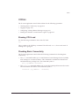
Configuring a Startup Banner Message
To configure a banner message to display after reboot, use the following command:
config banner
At the prompt, type the banner message. To exit the banner input script, type
[Return][Return].
To view the configured banner, use the following command:
show banner
Starting the GlobalPx Content Director Agent
Extreme Networks GlobalPx Content Director™ is a DNS-based Internet traffic
management system, allowing you to take advantage of network and server resources
regardless of their location on the Internet or your Intranet. As you add points of presence
(POPs, clusters of one or more Px-series switches) to a network, GlobalPx Content
Director monitors server loads and network response latencies, distributing client
requests to the POP that it determines will deliver the best performance. GlobalPx
Content Director improves client access performance and reliability by leveraging
dispersed network resources.
The GlobalPx Content Director transparently directs clients and client DNS servers to
the most appropriate POP to satisfy client requests. Typically, the physically closest POP
is the one that gives the fastest response. However, this is not always the case. The
GlobalPx Content Director scheduler routes requests to the optimal POP. In determining
the optimal POP, the scheduler receives the following information from the Px series
application switch that runs the agents that monitor each POP:
• Client/server network latency—The time it takes for information to travel from the
POP to the client. The closest POP in terms of response time exhibits the least
latency.
• Real-time server load—The computing burden of the POP. The least loaded POP can
handle requests most quickly.
• Server availability—Only those POPs that are running and available are eligible to
receive requests. Requests are scheduled around failed POPs. Once an unavailable
POP comes back up, the scheduler includes it again as a possible POP for selection.
To minimize response time to the client, requests are directed to servers at a POP that is
available and that has the smallest network latency and load.
Px Series Application Switch Installation and Configuration Guide
4-17
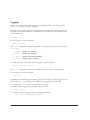
To start and stop the GlobalPx Content Director agent on the Px series application
switch, use the following commands:
enable gslb-agent [port <number>]
disable gslb-agent
To check on the agent’s activities, use the following command:
show gslb-agent
gslb-agent is [enabled | disabled]
listening on IP address a.b.c.d:port
last contacted by scheduler ipaddr at time
contacted by schedulers: ipaddr ipaddr ipaddr …
current load: <num>
For more information, see the GlobalPx Content Director Installation and User Guide.
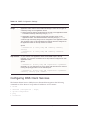
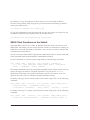
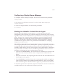
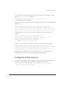
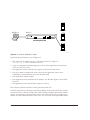
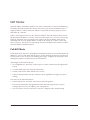
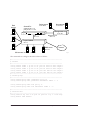
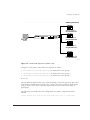
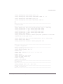
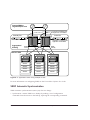
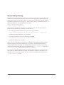
Example Configuration
In the following example, a Px series application switch is installed in a site with a
syslog server and network manager on a back end management network, and a DNS
server on the main network.
SummitPx1
Syslog server
Net manager
10.10.10.20
10.10.10.21
system IP 64.1.1.10
proxy IP 64.1.1.11-24
Management net
10.10.10.1
Management IP
64.1.1.10
Layer 3 switch
64.1.1.1
Internet
DNS server
64.1.1.9
WS_015
4-18
Px Series Application Switch Installation and Configuration Guide
Example Configuration
The following commands configure all system-related facilities:
#---------------------------------------------------------------# system configuration
#---------------------------------------------------------------config system-ip 64.1.1.10 / 24
config default-gateway 64.1.1.1
disable vlan
config mgmt ipaddress 10.10.10.10 / 24
enable syslog
config syslog ip 10.10.10.20
config nat-mode full
enable clipaging
disable port gigabit
#---------------------------------------------------------------# proxy-ip's
#---------------------------------------------------------------config proxy-ip 64.1.1.11 - 64.1.1.42
#---------------------------------------------------------------# SNMP configuration
#---------------------------------------------------------------config snmp sysName “balancer”
config snmp sysLocation “Exodus Colo”
config snmp sysContact “Web Admin”
config add trap receiver 10.10.10.21 “public” 162
config snmp add community readonly “readme”
config snmp add community readwrite “doall”
Px Series Application Switch Installation and Configuration Guide
4-19
4-20
Px Series Application Switch Installation and Configuration Guide
5
Configuring Servers and Services
This chapter describes how to configure the real servers that will be load balanced, how
to create groups of servers and put the real servers into them, and how to create a layer
4 or layer 7 virtual service. It contains the following sections:
• Configuring Real Servers on page 5-1
• Configuring Server Groups on page 5-2
• Configuring Virtual Services on page 5-3
• Configuration Example on page 5-6
Configuring Real Servers
The real servers are the actual web or application servers that fulfill the client requests.
Typically, there are one or more identical real servers, each of which runs the same
application and contains the exact same content.
To configure a server use the following command:
config server index <number> ipaddress <ipaddress> port <number>
max-connections <number> weight <number>
• Each server must have a unique index number. The index number can be used to
perform operations on several different servers at once.
• Each server must have one IP address and port. The IP address is the actual IP
address of the server, and the port number is the IP port that the server uses to
Px Series Application Switch Installation and Configuration Guide
5-1
answer requests. Servers can share an IP address, but the port must be unique for
each server.
• Max-connections represents the maximum number of concurrent connections this
server can handle. After that number is reached, no more connections are sent to that
particular server until some of the open ones have been closed (unless a persistence
method is specified; see “Persistence Modes” on page 6-2). Most servers can handle
fewer than 5,000 connections.
• Weight is used by weighted algorithms for load balancing. Use equal weights for all
servers (or 1 for simplicity’s sake) with non-weighted algorithms. See Chapter 6.
If servers are configured at contiguous IP addresses, and have identical attributes, you
can specify many identical servers at once using a range of IP addresses. The specified
index is used for the first server and incremented for each configured server. The
following example creates servers with indexes 3 through 10:
config server index 3 ipaddress 10.2.2.2 - 10.2.2.9 port 80
max-connections 4000 weight 1
To remove a server or range of servers from the system, use the following commands:
unconfig
unconfig
unconfig
unconfig
server
server
server
server
index <index>
index <index> - <index2>
ipaddress <ipaddress>
ipaddress <ipaddress> - <ipaddress>
Configuring Server Groups
After all of the servers needed for a particular virtual service have been created, they
must be organized into a server group. This group is used in the definition of the virtual
service itself. The following command creates a server group:
config server-group name <string> policy [rr | wrr | lc | wlc]
Each server group definition includes a unique name, used when configuring the server
group or used elsewhere in the configuration. A load balancing policy is the method of
choosing servers. See Chapter 6 for policy details.
You can optionally specify a server of last resort for the group. This is a server to which
traffic is sent if all the servers in a server-group are down. It could be a server that
simply replies to the client with a "SYSTEM DOWN" message, or a server that can
service the request under emergency circumstances (perhaps a development machine or
5-2
Px Series Application Switch Installation and Configuration Guide
Configuring Virtual Services
a system in another geographical location). To specify the server of last resort, use the
optional server-last-resort argument:
config server-group name <string> policy <policy spec>
server-last-resort <index>
After a server-group is created, add a server or range of servers to it using the following
commands:
config
config
config
config
server-group
server-group
server-group
server-group
name
name
name
name
<group
<group
<group
<group
name>
name>
name>
name>
add-server
add-server
add-server
add-server
index <number>
ip-address <ip>
index <index - index2>
ip-address <ip - ip>
You can specify a server or range of servers by IP address or by server index. For
example:
config server-group name
config server-group name
config server-group name
config server-group name
ip-address 10.10.10.2
group1 add-server index 1
group1 add-server ip-address 10.10.10.2
group1 add-server index 1 - 34
group1 add-server
- 10.10.10.15
To delete a server or range of servers from a group, use the following commands:
config
config
config
config
server-group
server-group
server-group
server-group
name
name
name
name
<name>
<name>
<text>
<name>
delete-server
delete-server
delete-server
delete-server
index <index num>
index <index> - <index2>
ip-address <ip>
ip-address <ip - ip>
This removes the specified server (or servers) from the server group, but leaves it
configured in the system, so that it can be added to a different group.
Configuring Virtual Services
The virtual service is the IP address and port to which clients on the Internet actually
connect. Use the following basic command to configure a virtual service:
config service vip <ip address> port <number> protocol [tcp|udp]
[L4|L7] server-group-name <label>
Px Series Application Switch Installation and Configuration Guide
5-3
You can assign a specific VLAN tag to a virtual service. VLAN tags for services are
optional for the SummitPx1, but required on the PxM. To assign a VLAN tag to a
service, use the following command:
config service vip <ip address> vlan <vlan_tag_number> port <number>
protocol [tcp|udp] [L4|L7] server-group-name <label>
Layer 4 Port-based Load Balancing
A layer 4 service does not examine traffic and make decisions based on cookies or
URLs. Layer 4 virtual services include the virtual IP address (VIP), the IP port of the
service, the protocol (tcp or udp), and the name of the server group to use.
Define layer 4 services with the following command:
config service vip <ipaddress> port <number> protocol [tcp|udp]
L4 server-group-name <name>
You can configure a layer 4 service on a VLAN, using the optional vlan argument:
config service vip <ip address> vlan <vlan name> port <number>
protocol [tcp|udp] L4
Layer 7 Virtual Services
Layer 7 virtual services require a more complex configuration, because they must
include information about what domains, URLs, and cookies should be processed. Use
the following commands to configure layer 7 virtual services:
config service vip <ipaddress> port <number> proto [tcp|udp] L7
class [http | https]
The class of application that the VIP supports is either http for regular web traffic,
or https for SSL session persistence. You can also specify a VLAN using the
optional vlan argument.
config domain name <string or ipaddress>
Domain names refer to the DNS domains that are used at the service. Domains are
always required. If you use only the URL to make your server selection, use the
special domain name domain*.
5-4
Px Series Application Switch Installation and Configuration Guide
Configuring Virtual Services
config pattern-rule “<string>” server-group-name <name>
Pattern rules specify the URL that is being matched and the server group that
should be used to forward traffic for that URL match.
config domain default
config pattern-rule default server-group-name <name>
All layer 7 service definitions require at least a default pattern rule, to define the
“last resort” rule for URL switching. If you use any domain other than domain*, you
must define a default domain. The default domain can only contain one pattern rule:
the default. These defaults also provide the place to configure cookie and SSL
persistence:
config pattern-rule default server-group-name <name> cookie-name <name>
cookie-type [self | hash | learned]
Cookie-name is the ASCII name of the cookie to search for, and cookie type refers to
the type of cookie-based persistence for the virtual service. Although you configure
cookies for the default domain, the cookie information applies to the entire site. See
Chapter 6 for more information on cookies.
Configuring Traffic Tagging
You can configure a service to tag traffic based on the application or transaction type.
You can then use the tag for QoS, MPLS tunneling, or bandwidth reservation, all
enforced by the L2/3 infrastructure.
You can specify tags for the 802.1p header and the DiffServ code point (DSCP) in the
TCP header. You can tag either or both of these fields. You can specify different tags for
traffic towards the server and traffic towards the network.
• For level 4 services, configure the service itself for tagging:
config service vip <addr> port <port> proto tcp L4 <tag spec>
• For level 7 services, create rules to apply the tags, so that when a session is initiated,
the flow is tagged with the specified values.
config
config
config
<tag
service vip <addr> port <port> proto tcp L7 class http
domain name <domain>
pattern-rule [<url>|default] server-group-name <grp>
spec>
Table 5-1 shows the possible tag specifications.
Px Series Application Switch Installation and Configuration Guide
5-5
.
Table 5-1: Tag Specifications
Tag Specification
Description
Tag Range
dot1p-to-svr <tag>
Applies the specified tag to the 802.1p header for
packets directed to the server.
0-7
dot1p-to-net <tag>
Applies the specified tag to the 802.1p header for
packets directed to the network.
0-7
diffserv-to-svr <tag> Applies the specified tag to the DiffServ code point
for packets directed to the server.
0 - 0x3F
diffserv-to-net <tag> Applies the specified tag to the DiffServ code point
for packets directed to the network.
0 - 0x3F
Configuration Example
The example builds upon the example from Chapter 4 and includes configurations for
the simple layer 4 web server infrastructure for yourdomain.com. Notice that VLANs
and the system-ip address definition have been added to the configuration.
SummitPx1
Syslog server
Net manager
10.10.10.20
10.10.10.21
system IP 64.1.1.10
proxy IP 64.1.1.11-24
Management net
10.10.10.1
VIP
64.1.2.10
Management IP
64.1.1.10
Layer 3 switch
64.1.1.1
Internet
Real
servers
64.1.1.50
DNS server
64.1.1.9
64.1.1.51
64.1.1.52
WS_016
For layer 7 examples, consult later chapters in this book.
5-6
Px Series Application Switch Installation and Configuration Guide
Configuration Example
#---------------------------------------------------------------# servers
#---------------------------------------------------------------config server index 1 ip 64.1.1.50 port 80 max-con 5000 weight 1
config server index 2 ip 64.1.1.51 port 80 max-con 5000 weight 1
config server index 3 ip 64.1.1.52 port 80 max-con 5000 weight 1
#---------------------------------------------------------------# server-groups
#---------------------------------------------------------------config server-group name yourdomain policy rr
config server-group name yourdomain add-server index 1 - 3
#---------------------------------------------------------------# service-table
#---------------------------------------------------------------config service vip 64.1.2.10 port 80 protocol tcp l4 server-group-name
yourdomain
#---------------------------------------------------------------# system configuration
#---------------------------------------------------------------config system-ip 64.1.1.10 / 24
config default-gateway 64.1.1.1
disable vlan
config mgmt ipaddress 10.10.10.10 / 24 vlan 100
enable vlan
enable syslog
config syslog ip 10.10.10.20
config nat-mode full
enable clipaging
disable port gigabit
#---------------------------------------------------------------# proxy-ip's
#---------------------------------------------------------------config proxy-ip 64.1.1.11 - 64.1.1.42
#---------------------------------------------------------------# SNMP configuration
#---------------------------------------------------------------config snmp sysName “balancer”
config snmp sysLocation “Exodus Colo”
config snmp sysContact “Web Admin”
config add trap receiver 10.10.10.21 “public” 162
config snmp add community readonly “readme”
config snmp add community readwrite “doall”
Px Series Application Switch Installation and Configuration Guide
5-7
5-8
Px Series Application Switch Installation and Configuration Guide
6
Choosing Policies, Persistence
Modes, and NAT
This chapter describes how to specify scheduling polices for layer 4 load balancing,
session persistence, and network address translations. It contains the following sections:
• Scheduling Policies on page 6-1
• Persistence Modes on page 6-2
• NAT Modes on page 6-14
• Configuration Example on page 6-17
Scheduling Policies
The Px series application switch uses scheduling policies in load balancing to select the
real server to which to forward a client request. Scheduling policies are specified as part
of the server-group command. This means that any service that uses a specific server
group uses the policy defined for that group.
If different policies are needed for services using the same server group, simply create
another group with the same members, but with a different policy selected, using the
following command:
config server-group name <string> policy [lc |rr | wlc |wrr]
Px Series Application Switch Installation and Configuration Guide
6-1
The Px series application switch supports the following scheduling policies:
Table 6-1: Scheduling Policies
Specifier Policy
rr
round robin
Description
Distributes clients evenly across the web server group by passing each
new connection request to the next server in line. The first client
connection is sent to the first server, the second to the second server,
and so on, until each server has a connection. When each server has
its first connection, the next client connection is sent to the first server,
the next to the second, and so on.
Round robin is the simplest way of balancing web traffic, and is best
suited for environments where the performance level of all servers is
about equal, and all servers provide the same content.
wrr
weighted
round robin
Similar to round robin, except that you can apply a weight to each
server. For example, if server A has a weight of two, and server B has
a weight of one, server A receives two connections for each connection
given to server B.
Weighted round robin is useful if all servers provide the same content,
but some are faster than others.
lc
least
Passes a new connection to the server having the least number of
connections active sessions. It distributes clients based on the server with the least
connections currently open.
The least connections policy provides the best performance under most
conditions.
wlc
weighted
As in weighted round robin, assigns a weight to each server. The weight
least
can be based on a number of things, including:
connections
■
Processor speed
■
Network connection speed
Connections are distributed using the servers with the least connections
by weight. As in weighted round robin, weighted least connections can
be used if servers have very different connection handling capacities.
Weighted least connections has the advantage of not overloading older,
slower servers with too many connections.
Persistence Modes
Persistence, also called stickiness, is the maintenance of a session between a client and a
particular web server. Most medium- and large-scale websites have multiple, redundant
web servers that are run in parallel and contain duplicate information. When a client
6-2
Px Series Application Switch Installation and Configuration Guide
Persistence Modes
accesses the website, it opens a session with one of the web servers. To optimize the
communication and, in many cases, for the website to function correctly, each time the
client communicates with the website within the current session, the client must
communicate with the web server that established the session.
The Px series application switch provides the following types of persistence:
• UDP persistence
• Client IP persistence
• Cookie persistence
• SSL session identifier persistence
UDP Flow Persistence
A UDP flow is recycled if it is idle for the time specified by the UDP-flow-persistence
timer. To set this timer, use the following command:
config timeout udp-flow-persistence <seconds>
The default value for the timer is 40 seconds.
Client IP Persistence Mode
Client IP persistence mode is a layer 4 mode for establishing stickiness. In this mode,
the application switch examines the IP address in the client request. Each time the
application switch receives a request from the same IP address, the application switch
forwards the request to the same web server.
Figure 6-1 illustrates client IP persistence mode.
Px Series Application Switch Installation and Configuration Guide
6-3
Server 1
145.12.1.1
Client
64.1.1.7
www.buystuff.com
Server 2
Server 3
WS_001
Figure 6-1: Client IP persistence mode
The following transactions occur in Figure 6-1:
• The client with IP address 145.12.1.1 transmits its first TCP request to
www.buystuff.com at its VIP address, 64.1.1.7.
• Using its configured load balancing policy, the Px series application switch selects
server 3 as the web server.
• The application switch sends the first request to the selected web server.
• The server sends a request back to the client via the application switch, thus
establishing a session between the server and the client.
• The client sends another request.
• The application switch examines the IP address, sees that the request is from client
125.12.1.1.
• The application switch forwards the request to server 3.
This scenario continues until the session persistence times out.
Client IP persistence mode requires that the IP address of the client remain the same for
the entire session. It does not work if the client IP address changes dynamically within a
session; for example, for large ISPs that conserve IP addresses by using a single proxy
address for many different clients. In this case, use one of the cookie persistence modes.
6-4
Px Series Application Switch Installation and Configuration Guide
Persistence Modes
Configuring Client IP Stickiness
To enable and disable client IP persistence (stickiness), use the following commands:
[enable | disable] sticky [L4 | L7] client-ip
Client IP entries are aged out of the database in a configurable amount of time. By
default, they are deleted after 30 seconds without use. To adjust these timers, use the
following command:
config sticky client-ip timeout HH:MM:SS
The timer affects both layer 4 and layer 7. Valid values are in the range 00:00:05 (5
seconds) to 97:43:52. You can specify the value infinity to indicate that the stickiness
should last forever.
Cookie Persistence Modes
Cookie persistence modes are layer 7 methods for establishing stickiness. When a client
accesses a web server, the web server can send the client a cookie. The cookie can be
programmed to contain many different pieces of information, including:
• The IP address of the web server
• A session identifier
• The expiration timer for the cookie
• Other information generated by the server
Each time the client sends a request to the server, the cookie is sent as part of the
transmission. Using cookie persistence modes, the Px series application switch examines
information in the cookie and uses that information to maintain the session with the
appropriate web server.
The Px series application switch supports three cookie persistence modes:
• Self-identifying cookie persistence
• Hashed cookie persistence
• Learned cookie persistence
Self-Identifying Cookie Persistence Mode
Using self-identifying cookie persistence, the web server places its real IP address in the
cookie. Figure 6-2 illustrates self-identifying cookie persistence mode.
Px Series Application Switch Installation and Configuration Guide
6-5
Server 1
10.1.1.1
64.1.1.7
A
www.buystuff.com
B
C
E
Client
F
D
F
Server 2
10.1.1.2
E
Cookie:
serverip=10.1.1.3
Server 3
10.1.1.3
WS_002
Figure 6-2: Self-identifying cookie persistence mode
The following transactions occur in Figure 6-2:
• The website administrator of www.buystuff.com sets up each web server (server 1,
server 2, and server 3) to create a cookie that contains the real IP address of the web
server.
— Cookies created by server 1 contain IP address 10.1.1.1.
— Cookies created by server 2 contain IP address 10.1.1.2.
— Cookies created by server 3 contain IP address 10.1.1.3.
• The website administrator configures the Px series application switch to use
self-identifying cookie persistence mode.
• The client transmits its first TCP request (A) to www.buystuff.com at its
publicly-known VIP address, 64.1.1.7.
• The Px series application switch responds (B) on behalf of 64.1.1.7, and the three-way
TCP handshake is established between the client and the Px series application
switch.
6-6
Px Series Application Switch Installation and Configuration Guide
Persistence Modes
• Using its configured load balancing policy, the Px series application switch selects
one of the web servers. In this example, server 3.
• A three-way TCP handshake is established between the Px series application switch
(C) and server 3 (D).
• The application switch forwards the first data request from the client to server 3 (E).
• The first response from server 3 to the client contains a cookie. (F). The cookie
contains the real IP address of the server, 10.1.1.3.
• Each subsequent request sent from the client to the website contains the cookie.
• The application switch examines the cookie and sends each request from this client
to server 3. If server 3 fails health checks, the request will be forwarded to another
server.
The following Perl example sends a cookie to the user’s browser, and handles the case
of server failure. If the chosen server fails, then a request will come to a server that
contains the wrong IP address. In this case, the program responds by sending a new
cookie that creates persistence to the new server.
#!/usr/bin/perl
#
# Check and set or reset Server Load Balancer host cookie example
# Uses CGI.pm available at CPAN (www.cpan.org)
use CGI qw(:standard);
$SLBCookie = 'sticky_slba'; # Name of cookie SLB switches on
$HostIPAddr = '10.10.10.106'; # This server's private IP Address
$query = new CGI;
$ExistingHostCookie = $query->cookie($SLBCookie); #Retreive the cookie
if ($ExistingHostCookie ne $HostIPAddr) {
#If not set correctly
$NewHostCookie = $query->cookie(-name=>$SLBCookie,
-value=>$HostIPAddr);
#Build a new cookie
print $query->header(-cookie=>$NewHostCookie); #include in the header
}
else {
# The cookie is correct
print $query->header;
# So nothing extra in the header
}
# Example done
Px Series Application Switch Installation and Configuration Guide
6-7
# Additional information may be useful during debugging
print start_html('Cookie Tester');
if (!$ExistingHostCookie) {
print "No cookie named $SLBCookie existed<br>\n";
print "It was set to the local host address of $HostIPAddr<br>\n";
}
elsif ($ExistingHostCookie ne $HostIPAddr) {
print "The cookie named $SLBCookie was set for host
$ExistingHostCookie<br>\n";
print "It was reset to the local host address of $HostIPAddr<br>\n";
}
else {
print "The cookie named $SLBCookie was correctly set to
$ExistingHostCookie<br>\n";
print "No action was taken<br>\n";
}
print end_html;
Hashed Cookie Persistence
Using hashed cookie persistence, unique information about the client is placed in the
cookie. When the application switch examines the cookie, it performs a mathematical
hash of the unique contents of the cookie. The mathematical hash operation always
renders the same numeric value for the cookie. In other words, a given cookie is always
forwarded to the same server until the size of the server pool changes.
Figure 6-3 illustrates hashed cookie persistence.
6-8
Px Series Application Switch Installation and Configuration Guide
Persistence Modes
user=samsmith96754
D
A
B
F
E
64.1.1.7
Server 1
rs
ive ie
l
De ook
c
www.mybank.com C
Database
E
Server 2
ss
se
G
ta
G
Da
Client
n
io
Sam Smith
Server 3
WS_003
Figure 6-3: Hashed cookie persistence mode
Figure 6-3 shows a typical financial website named www.mybank.com. This website has
three real servers, each connected to a single backend database system. To minimize
time-consuming database “hits,” when a client makes a request of a web server, the web
server queries the backend database and caches the client data. In this example, it is
critical that the client always access the same web server that contains its cached
information. In addition, before accessing the web server, the client must login to the
site and obtain a unique cookie.
The following transactions occur in Figure 6-3:
• The website administrator of www.mybank.com sets up each web server (server 1,
server 2, and server 3) to create a cookie that contains unique identifying
information about each client.
• The website administrator configures the Px series application switch to use hashed
cookie persistence mode.
Px Series Application Switch Installation and Configuration Guide
6-9
• The client transmits its first TCP request (A) to www.mybank.com at its
publicly-known VIP address, 64.1.1.7.
• The Px series application switch responds (B) on behalf of 64.1.1.7, and the three-way
TCP handshake is established between the client and the Px series application
switch.
• Using its configured load balancing policy, the Px series application switch selects
one of the web servers. In this example, server 1.
• A three-way TCP handshake is established between the Px series application switch
(C) and server 1 (D).
• The application switch forwards the first data request (E) from the client to server 1.
• Server 1 sends a cookie to the client (via the application switch) (F). The cookie
contains unique identifying information for this client session. For example, the
cookie could contain the username:
user=samsmith96754
• Each subsequent request sent from the client to the website contains the cookie.
• The client sends another data request to the website (via the application switch).
• The application switch examines the cookie and performs a mathematical hash
operation on the cookie, rendering a numeric value.
The selected server may or may not be the same server that provided the client
cookie.
• The application switch examines the cookie, performs the same mathematical hash
on the cookie, renders the same numeric value each time, and sends each subsequent
request from this client to server 3.
Learned Cookie Persistence Mode
Using learned cookie persistence, the Px series application switch creates a database
that stores historical information about each session. The database contains the
following information:
• Cookie
• Source IP address
• Destination VIP address
• Real server IP address
The application switch uses the stored information to match the incoming cookie with
the previous connection made by the same client.
6-10
Px Series Application Switch Installation and Configuration Guide
Persistence Modes
Unlike self-identifying cookie persistence and hashed cookie persistence, learned cookie
persistence does not require the website administrator to make any changes to the
website. Learned cookie persistence is a best-effort persistence mode that creates a
short-term stickiness between the client and the web server.
Figure 6-4 illustrates learned cookie persistence mode.
Server 1
10.1.1.1
64.1.1.7
A
www.buystuff.com
B
C
E
Client
65.11.11.11
F
D
F
Server 2
10.1.1.2
E
Cookie:
sessionID=37654
Server 3
10.1.1.3
WS_004
Figure 6-4: Learned cookie persistence mode
The following transactions occur in Figure 6-4:
• The website administrator configures the Px series application switch to use learned
cookie persistence mode, and configures the name of the cookie to be tracked.
• The client at IP address 65.11.11.11 transmits its first TCP request (A) to
www.buystuff.com at its publicly-known VIP address, 64.1.1.7.
• The Px series application switch responds (B) on behalf of 64.1.1.7, and the three-way
TCP handshake is established between the client and the Px series application
switch.
• Using its configured load balancing policy, the Px series application switch selects
one of the web server. In this example, server 3 at IP address 10.1.1.3.
Px Series Application Switch Installation and Configuration Guide
6-11
• A three-way TCP handshake is established between the Px series application switch
and server 3.
• The application switch makes the following entry in its database:
Cookie
Source
IP Address
Destination
VIP Address
Real Server
IP Address
65.11.11.11
64.1.1.7
10.1.1.3
• The application switch forwards the first data request from the client to server 3 (E).
• Server 3 sends a cookie to the client (via the application switch) (F). The cookie
contains randomly generated information that is unique for this client, such as a
session identifier:
sessionID=37654
• The client sends another data request to www.buystuff.com (via the application
switch).
• The application switch examines the source IP address of the client and looks for a
match in the database table.
• The application switch completes the database record by entering the cookie
information:
Cookie
Source
IP Address
Destination
VIP Address
Real Server
IP Address
sessionID=37654
65.11.11.11
64.1.1.7
10.1.1.3
• Each subsequent request sent from the client to the website contains the cookie.
• The application switch examines the cookie, looks up the forwarding information in
the database, and sends each request from this client to server 3.
Learned cookie persistence mode is based on the assumption that the client IP address
will not change between the first and second data requests sent to the website. After the
cookie is established and entered in the table, the source IP address of the client is no
longer examined, and can change as frequently as required by the ISP.
Configuring Cookie Stickiness
To configure cookie persistence you must add information to the end of the pattern-rule
definition for the default domain. This means that even if no domain or URL switching
6-12
Px Series Application Switch Installation and Configuration Guide
Persistence Modes
is being done, a default domain and pattern rule are still needed. The commands are as
follows:
config domain default
config pattern-rule default server-group-name <name>
cookie-name <cookie name> cookie-type [self | hash | learned]
Because learned cookie mode uses a database to track users, there is a configurable
timer. If a database entry has not been used for the amount of time specified by the
timer, the database entry is deleted. To configure the timer, use the following command:
config sticky cookie-id timeout HH:MM:SS
The timer affects both layer 4 and layer 7. Valid values are in the range 00:00:05 (5
seconds) to 97:43:52. You can specify the value infinity to indicate that the stickiness
should last forever.
NOTE: Although you configure it in the default domain, the cookie mode applies to the
whole service, not just the default domain.
SSL Session Identifier Persistence
Websites that use SSL encrypt all transmitted information in the SSL session except the
SSL session identifier. SSL session identifier persistence works in the same way as
learned cookie persistence, except it uses the SSL session identifier instead of a cookie to
bind the client and server in the session.
Configuring SSL is done on the main line of the service definition, as follows:
config service vip <ip address> port <number> protocol tcp L7
class https
config domain default
config pattern-rule default server-group-name <name>
SSL Session ID database entries have a separate timer. If a database entry has not been
used for the amount of time specified by the timer, then the database entry is deleted.
To configure the timer, use the following command:
config sticky session-id timeout HH:MM:SS
The timer affects both layer 4 and layer 7. Valid values are in the range 00:00:05 (5
seconds) to 97:43:52. You can specify the value infinity to indicate that the stickiness
should last forever.
Px Series Application Switch Installation and Configuration Guide
6-13
NAT Modes
Network address translation (NAT) is one of the cornerstones of server load balancing.
To balance the load between the various real servers, the server load balancer uses a
single IP address, called a virtual IP address, to represent the entire group of servers
that make up a website.
When a client request arrives at the virtual IP address, the load balancer must rewrite
the destination IP address, so that it can forward the request to a server for processing.
Likewise, when the server responds to the request, the server address must also be
translated from its own unique address to that of the virtual IP, so that it can be sent
back to the user. This process of translating one network address into another is called
network address translation (NAT).
Full-NAT Mode
In full-NAT mode, the server load balancer translates both the source and destination IP
addresses—those of the client and the server—before sending the request onto the user.
For the point of view of the server fulfilling the request, it appears as though the client
making the request is actually the server load balancer.
Advantages of full-NAT mode are:
• No configuration is necessary on the Layer 2/3 switch connected to the application
switch.
• It can be deployed in any network architecture.
• Clients can be on the same subnet as the servers.
• It allows interoperation with any vendors switch, regardless of support for policy
routing.
You must run in full-NAT mode if:
• Clients and servers are on the same layer 2 network segment.
• The switch connected to the application switch does not support layer 3 policy
routing based on source IP address, port, and protocol.
• You do not have access to the layer 3 switch to configure policy based routing.
6-14
Px Series Application Switch Installation and Configuration Guide
NAT Modes
Configuring Full-NAT Mode and Proxy IP Addresses
Full-NAT mode is the default behavior of the application switch. If another NAT mode
was in use previously, use the following command to set it back to full:
config nat-mode full
To function properly, the application switch requires that proxy IP addresses be
configured. These proxy addresses are used as the source IP addresses for the outbound
connection to the server. One proxy address must be configured for each 63,000 sessions
active at one time. For full system capacity, you must configure 32 IP addresses.
To set a proxy IP address or a range of proxy addresses, use the following command:
config proxy-ip <ip address1> [- <ip address2>]
Proxy-ip addresses do not need to be contiguous. You can use multiple commands to
specify different ranges of IP addresses to use as proxy addresses. The only restriction is
that all addresses must be on the same subnet as the main system IP address.
Do not change the proxy IP while the application switch is running. Boot the
application switch for the proxy IP information to take effect.
Server-only Half-NAT Mode
In half-NAT mode, the application switch only translates the server IP address when
dispatching the client requests to the real server. Half-NAT mode results in the server
believing that the request came from the client, instead of the application switch. Using
half-NAT mode, the server sees the real IP address of the client.
Because the server fulfilling the request believes that the request came directly from the
actual client, and not the application switch, the server attempts to respond directly to
the client. However, for the connection to be completed appropriately, the application
switch needs to see the return traffic so that it can perform reverse NAT on the server
portion of the address.
To route the traffic correctly from the server back into the application switch, and back
to the client, the layer 3 switch attached to the application switch must support
policy-based routing.
Policy-based routing allows layer 3 switches to make next-hop forwarding decisions
based on information other than simply the IP destination address of the request. In this
case, the next-hop decision must be based on the fact that the source of the request is
Px Series Application Switch Installation and Configuration Guide
6-15
that of the real server, and that the TCP source port for the request is the same as the
port of the network service that is being load balanced. If a request meets these criteria,
it should be sent to the application switch as its next hop.
Advantages of Half-NAT mode are:
• Allows the server logs on the real website to reflect the IP address of the real client
making a request, rather than a proxy address of the application switch.
• Allows the use of IP address based security methods such as Unix Netgroups. This
is primarily a concern for enterprise data centers.
Half-NAT mode cannot be used if:
• Clients and servers are on the same layer 3 network. Policy-based routing occurs at
layer 3 and cannot be applied without crossing a layer 3 network boundary.
Configuring Half-NAT Mode
Half-NAT mode must be configured on both the application switch and the attached
layer 3 switch. To enable half-NAT on the Px series application switch, use the
following command:
config nat-mode server-only
On an Extreme switch, use the following ExtremeWare commands to configure the
policy routes required for half-NAT:
create source-flow <name> source-ip <server ip> source-port
<server-port> protocol tcp destination any
config source-flow <name> next-hop <SLB VIP>
These policy rules route all traffic from the load balanced port on the server to the
application switch. If other locally-attached networks need to use the facility provided
by that port without using the load balancer, more specific rules need to be written to
steer traffic directly back to the correct routers.
For example, if users on the segment 10.1.1.0 are connecting to a Web server on 10.1.2.0
without using the server load balancer, you would need another rule group such as the
following:
create source-flow local-traffic source-ip 10.1.2.0/24 source port 80
protocol tcp destination 10.1.1.0/24
config source-flow local-traffic next-hop 10.1.2.1
6-16
Px Series Application Switch Installation and Configuration Guide
Configuration Example
When you configure half-NAT mode, you can also configure gateway mode for the
application switch. Gateway mode specifies an IP address that a server’s default
gateway can forward to, as if the application switch were another router. The
application switch can then switch the forwarded traffic to another router, even one on
another VLAN.
To enable and configure gateway mode on the application switch, use the following
commands:
enable gateway-mode
config gateway-mode add ip <ip address> [vlan <vlan tag>]
If VLAN tags are enabled, you must specify the VLAN tag for gateway mode.
If gateway mode is enabled, set up a policy rule on the server’s default gateway to
forward to the gateway-mode IP address of the application switch. For example:
config source-flow <name> next-hop <gateway-mode ip>
Configuration Example
In the configuration example, yourdomain.com needs to get around the mega proxy
problem, but does not have time to rewrite much of their site. Instead, they move to
using learned cookies for the main web servers. They also add two SSL servers for
secure web transactions, and configure SSL session persistence. Because they want to
gather more information about who their users are, they also move to server-only NAT
mode.
Px Series Application Switch Installation and Configuration Guide
6-17
Real
servers
SummitPx1
Syslog server
Net manager
10.10.10.20
10.10.10.21
system IP 64.1.1.10
proxy IP 64.1.1.11-24
Management net
10.10.10.1
64.1.1.50
64.1.1.51
Management IP
64.1.1.10
VIP
64.1.2.10
Layer 3 switch
64.1.1.1
DNS server
64.1.1.52
SSL servers 64.1.1.60
Internet
64.1.1.9
64.1.1.61
WS_017
The commands to configure this network are as follows:
#---------------------------------------------------------------# servers
#---------------------------------------------------------------config server index 1 ip 64.1.1.50 port 80 max-con 5000 weight
config server index 2 ip 64.1.1.51 port 80 max-con 5000 weight
config server index 3 ip 64.1.1.52 port 80 max-con 5000 weight
config server index 5 ip 64.1.1.60 port 443 max-con 500 weight
config server index 6 ip 64.1.1.61 port 443 max-con 500 weight
#---------------------------------------------------------------# server-groups
#---------------------------------------------------------------config server-group name yourdomain policy rr
config server-group name yourdomain add-server index 1 - 3
1
1
1
1
1
config server-group name ecom policy lc
config server-group name ecom add-server index 5 - 6
#---------------------------------------------------------------# service-table
#---------------------------------------------------------------config service vip 64.1.2.10 port 80 protocol tcp l7 class http
config domain name default
6-18
Px Series Application Switch Installation and Configuration Guide
Configuration Example
config pattern-rule “default” server-group-name yourdomain cookie-name
“session-id” cookie-type learn
config service vip 64.1.2.11 port 443 protocol tcp l7 class https
config domain name default
config pattern-rule “default” server-group-name ecom
#---------------------------------------------------------------# system configuration
#---------------------------------------------------------------config system-ip 64.1.1.10 / 24
config default-gateway 64.1.1.1
disable vlan
config mgmt ipaddress 10.10.10.10 / 24 vlan 100
enable vlan
enable syslog
config syslog ip 10.10.10.20
config nat-mode server-only
enable clipaging
disable port gigabit
#---------------------------------------------------------------# proxy-ip's
#---------------------------------------------------------------config proxy-ip 64.1.1.11 - 64.1.1.42
#---------------------------------------------------------------# SNMP configuration
#---------------------------------------------------------------config snmp sysName “balancer”
config snmp sysLocation “Exodus Colo”
config snmp sysContact “Web Admin”
config add trap receiver 10.10.10.21 “public” 162
config snmp add community readonly “readme”
config snmp add community readwrite “doall”
Px Series Application Switch Installation and Configuration Guide
6-19
6-20
Px Series Application Switch Installation and Configuration Guide
7
URL Switching
This chapter describes how the Px series application switch performs level 7 load
balancing, directing client requests to server groups by acting as a proxy and looking
inside each request, using domain or URL switching. The chapter covers the following
topics:
• Domain and URL Switching on page 7-1
• Configuring URL Switching on page 7-4
• Creating Domain and URL Switching Rules on page 7-8
• Configuration Example on page 7-9
Domain and URL Switching
In a typical scenario, such as the one shown in Figure 7-1, there are multiple server
groups, each serving different content to web users.
Px Series Application Switch Installation and Configuration Guide
7-1
Server Group 1
Outside
network
Server Group 2
Server Group 3
WS_005
Figure 7-1: Typical switching scenario
Domain Switching
Domain switching uses the requested domain name to select the appropriate server
group. For example, in Figure 7-2, there are three server groups:
•
www.buystuff.com
•
www.speakyourmind.net
•
www.buythisnow.net
7-2
Px Series Application Switch Installation and Configuration Guide
Domain and URL Switching
Server Group 1
www.buystuff.com
www.speakyourmind.net
192.1.1.1:80
Client
Server Group 2
www.speakyourmind.net
Server Group 3
www.buythisnow.net
WS_006
Figure 7-2: Domain switching example
The Px series application switch uses a single VIP, located at 192.1.1.1:80, to service all
three domains.
When the client request arrives, the application switch examines the request to
determine the domain name being requested. In Figure 7-2, the domain name requested
is www.speakyourmind.net.
Using domain name switching, the application switch matches the domain name to
server group 2. The application switch then uses the configuring server load balancing
policy (round robin, weighted round robin, least connections, or weighted least
connections) to select a particular server within the server group. The request is then
forwarded to the selected server in server group 2.
The following configuration shows the commands used to configure the combination of
the three websites. Another server group, mainpage, contains a page that allows the
user to self-select, just in case the domain specified by the user does not match either of
the three. This could happen, for example, if the actual IP address is used instead of a
host name.
config service vip 10.65.31.202 port 8080 proto tcp l7 class http
Px Series Application Switch Installation and Configuration Guide
7-3
config
config
config
config
config
config
config
config
config
config
config
config
config
config
domain name buystuff.com
pattern-rule default server-group-name
domain name www.buystuff.com
pattern-rule default server-group-name
domain name speakyourmind.com
pattern-rule default server-group-name
domain name www.speakyourmind.com
pattern-rule default server-group-name
domain name buythisnow.com
pattern-rule default server-group-name
domain name www.buythisnow.com
pattern-rule default server-group-name
domain default
pattern-rule default server-group-name
buystuff
buystuff
speakyourmind
speakyourmind
buythisnow
buythisnow
mainpage
URL Switching
URL switching takes the concept of domain name switching one step further by looking
deeper into the request. In addition to examining the domain name, the Px series
application switch examines the entire requested URL and matches it against a list of
pattern rules. Each of the pattern rules has its own associated server group.
URL switching allows you to control where traffic is sent based on the exact web object
a client is requesting. URL switching provides high flexibility and scales to meet your
needs. You can add, move, and change resources without changing links or
reconfiguring web servers.
Configuring URL Switching
Using URL switching, you can split your site into multiple groups of servers and add
rules to the application switch that directs traffic in the correct direction.
For example, as shown in Figure 7-3, a user might want to visit www.buystuff.com.
During the initial visit, the user simply requests www.buystuff.com. This request
returns a home page, such as /index.html. Subsequent clicks made by the user result in
requests for pages, such as www.buystuff.com/stereos or www.buystuff.com/dvds.
7-4
Px Series Application Switch Installation and Configuration Guide
Configuring URL Switching
www.buystuff.com
Server Group 1
default
Request 1:
www.buystuff.com
Client
Request 2:
www.buystuff.com/dvds
Server Group 2
/stereos
Server Group 3
/dvds
WS_007
Figure 7-3: Simple URL switching example
By directing each of these unique types of requests to a different pool of servers at the
application switch, you have the flexibility to move these resources without changing
dozens of links. You can also split out different sections of your website virtually
on-the-fly.
The larger the website, the more useful URL switching becomes. Figure 7-4 shows a
more complicated example.
Px Series Application Switch Installation and Configuration Guide
7-5
www.buystuff.com
Server Group 1
/ebooks/
ISBNxxxxxxxx
Client
Server Group 2
/ebooks/
ISBNxxxxxxxy
WS_008
Figure 7-4: More Complicated URL switching example
In Figure 7-4, buystuff.com decides to start selling electronic books online and they
need to store an entire publisher’s catalog on the site. Terabytes of storage are needed,
along with a flexible way of addressing all of the information. By using URL switching,
a highly scalable approach can be used. Expanding the website is as simple as loading
content onto servers and adding URL rules to the switch. In Figure 7-4, user requests
are directed as follows:
• www.buystuff.com/ebooks/ISBNXXXXXXX is directed to server group 1.
• www.buystuff.com/ebooks/ISBNXXXXXXX is directed to server group 2.
In fact, a unique rule could be used for each book in the catalog, with little danger of
exhausting the rules list. This approach simplifies the design of the website in many
ways:
• The need to track the location of the data is eliminated.
• The choice of where to store a book can be completely arbitrary.
• Content can be moved from one server to another quickly, without updating the
application server or any static web page links.
Alternatively, buystuff.com could use a more hierarchical approach to sorting content
and creating pattern rules, as shown in Figure 7-5.
7-6
Px Series Application Switch Installation and Configuration Guide
Configuring URL Switching
www.buystuff.com
Server Group 1
/ebooks/authorsa/*
Server Group 2
Client
/ebooks/authorsb/*
Server Group 3
/ebooks/authorsc/*
..
.
Server Group 26
/ebooks/authorsz/*
WS_009
Figure 7-5: Hierarchical approach to pattern rules
In Figure 7-5, the pattern rules direct user requests as follows:
• www.buystuff.com/ebooks/authorsa/* are directed to server group 1
• www.buystuff.com/ebooks/authorsb/* are directed to server group 2
• www.buystuff.com/ebooks/authorsc/* are directed to server group 3
and so on.
This hierarchical approach has most of the advantages of the first approach, and is also
well-suited to unindexed, browsable, static content. All of the content can be browsed
using a simple CGI or ASP script that inspects the file system and creates links, as
appropriate.
The following commands show the configuration for ebooks, using the hierarchal
method.
config service vip 10.65.31.201 port 8080 proto tcp l7 class http
Px Series Application Switch Installation and Configuration Guide
7-7
config
config
config
config
config
config
config
config
config
config
config
config
domain name www.ebooks.com
pattern-rule “authorsa” server-group-name authorsa
pattern-rule “authorsb” server-group-name authorsb
pattern-rule “authorsc” server-group-name authorsc
pattern-rule default server-group-name mainpage
domain name ebooks.com
pattern-rule “authorsa” server-group-name authorsa
pattern-rule “authorsb” server-group-name authorsb
pattern-rule “authorsc” server-group-name authorsc
pattern-rule default server-group-name mainpage
domain default
pattern-rule default server-group-name mainpage
Creating Domain and URL Switching Rules
To simplify the creation of pattern rules, you can use wildcard combinations. The
allowable wildcards are described in Table 7-1.
Table 7-1: Wildcard Combinations
Wildcard
Example
Definition
/exact-match/
/authors/
Match the entry exactly.
/end-wild/*
/authors/*/
Match any ending wildcard.
/middle/*/wildcard/
/authors/*/cookbooks/
Match an imbedded wildcard, but exact entry
following the wildcard.
/*.extension
/*.gif/
Match any entry with the listed extension.
/entry.*
/index.*/
Match any entry with the listed filename and
a wildcard extension.
Every layer 7 rule needs a default domain, which can contain only a default
pattern-rule. This rule is used to decide where to forward traffic in the event that none
of the configured rules match.
You can use a wildcard for the domain when the format of the domain is unknown or
unimportant. For example, the following configuration is for HTTP services with an
unknown domain format:
config service vip 10.65.101.20 port 80 protocol tcp l7 class http
config domain name *
config pattern-rule default server-group-name sg2
7-8
Px Series Application Switch Installation and Configuration Guide
Configuration Example
The wildcard (*) in the second line refers any request with an unspecified domain name
(any request in which the domain name is not present in the HTTP header) to the
default server group sg2.
The application switch reads the HTTP header to determine the domain name
format. You cannot configure HTTPS in this way because the header is
encrypted and not visible to the application switch.
Modifying Existing URL Rules and Domains
After a set of domains and pattern rules are put in place, they can be modified or
deleted at any time. Because they are context dependent, you must ensure that you are
in the correct context before modifying the rules.
To configure a domain, for example, you must first enter the virtual service that you
want to modify using the following command:
config service vip 10.65.31.201 port 8080 proto tcp l7 class http
Then you can add new domains, or delete an existing one:
unconfig domain name ebooks.com
If you want to modify another domain inside of the same service, first go into the
domain:
config domain name www.ebooks.com
Then, add or delete pattern rules:
config pattern-rule “comics” server-group-name comics
unconfig pattern-rule “authorsc” server-group-name authorsc
Configuration Example
The following configuration example expands on the examples in Chapter 5 and
Chapter 6. The site yourdomain has grown once again by using URL switching to
off-load delivery of static images and streaming media from their main servers. One of
the servers is redeployed as a media server.
To use cookies and URLs together, they modify the cookie so that it only applies to part
of their site, and they move all the images from that part of the site.
Px Series Application Switch Installation and Configuration Guide
7-9
SummitPx1
Syslog server
Net manager
10.10.10.20
10.10.10.21
system IP 64.1.1.10
proxy IP 64.1.1.11-24
Management net
Application
servers
64.1.1.50
10.10.10.1
Management IP
64.1.1.10
VIP
64.1.2.10
Internet
Layer 3 switch
64.1.1.1
Streaming media
64.1.1.80
64.1.1.51
64.1.1.60 64.1.1.61
64.1.1.70 64.1.1.71
SSL servers
Images
WS_018
The commands to configure this example are as follows:
#---------------------------------------------------------------# servers
#---------------------------------------------------------------config server index 1 ip 64.1.1.50 port 80 max-con 5000 weight 1
config server index 2 ip 64.1.1.51 port 80 max-con 5000 weight 1
config server index 5 ip 64.1.1.60 port 443 max-con 500 weight 1
config server index 6 ip 64.1.1.61 port 443 max-con 500 weight 1
config server index 10 ip 64.1.1.70 port 80 max-con 5000 weight 1
config server index 11 ip 64.1.1.71 port 80 max-con 5000 weight 1
config server index 20 ip 64.1.1.80 port 80 max-con 5000 weight 1
#
#
#---------------------------------------------------------------# server-groups
#---------------------------------------------------------------config server-group name appserv policy rr
config server-group name appserv add-server index 1 - 2
config server-group name ecom policy lc
config server-group name ecom add-server index 5 - 6
7-10
Px Series Application Switch Installation and Configuration Guide
Configuration Example
config server-group name images policy rr
config server-group name images add-server index 10 - 11
config server-group name media policy rr
config server-group name media add-server index 20
#
#
#---------------------------------------------------------------# service-table
#---------------------------------------------------------------config service vip 64.1.2.10 port 80 protocol tcp l7 class http
config pattern-rule “*.gif” server-group-name images
config pattern-rule “*.jpg” server-group-name images
config pattern-rule “*.mov” server-group-name media
config pattern-rule “*.mp3” server-group-name media
config domain name default
config pattern-rule “default” server-group-name yourdomain cookie-name
“session-id” cookie-type learn
config service vip 64.1.2.11 port 443 protocol tcp l7 class https
config domain name default
config pattern-rule “default” server-group-name ecom
#---------------------------------------------------------------# system configuration
#---------------------------------------------------------------config system-ip 64.1.1.10 / 24
config default-gateway 64.1.1.1
disable vlan
config mgmt ipaddress 10.10.10.10 / 24 vlan 100
enable vlan
enable syslog
config syslog ip 10.10.10.20
config nat-mode server-only
enable clipaging
disable port gigabit
#---------------------------------------------------------------# proxy-ip's
#---------------------------------------------------------------config proxy-ip 64.1.1.11 - 64.1.1.42
#---------------------------------------------------------------# SNMP configuration
#----------------------------------------------------------------
Px Series Application Switch Installation and Configuration Guide
7-11
config
config
config
config
config
config
7-12
snmp sysName “balancer”
snmp sysLocation “Exodus Colo”
snmp sysContact “Web Admin”
add trap receiver 10.10.10.21 “public” 162
snmp add community readonly “readme”
snmp add community readwrite “doall”
Px Series Application Switch Installation and Configuration Guide
8
Configuring Redundancy
This chapter describes how to configure redundancy for the Px series application
switch. For the SummitPx1, you use the industry standard VRRP. For the PxM, you use
the Extreme Standby Router Protocol (ESRP).
The chapter contains the following sections:
• Using VRRP with the SummitPx1 on page 8-1
• Configuring Redundancy for the PxM on page 8-6
• Configuring a Default Gateway on page 8-8
Using VRRP with the SummitPx1
To reduce downtime, the SummitPx1 supports the deployment of redundant systems
using VRRP, an industry standard failover mechanism (RFC 2338). In the event of the
failure of the primary active system, the secondary system automatically takes over for
the failed system.
VRRP uses a “phantom MAC” address at layer 2, which is negotiated using an election
protocol. After one of the application switches is elected “active,” the application
switches exchange keep-alive messages to ensure that the active system remains up. If
the redundant system loses connectivity for 3 seconds, the redundant system assumes
the active system is dead and it assumes traffic-forwarding duties. It promiscuously
sends ARP responses to poison the layer 2 forwarding information for the previously
active system and begin accepting traffic for the phantom MAC.
Px Series Application Switch Installation and Configuration Guide
8-1
The only difference between a traditional VRRP implementation and the Px series
application switch implementation is that instead of using the VRRP MAC address for a
single layer 3 router address, the Px series application switch uses the VRRP MAC
address for all VIPs configured in the system. Whenever the VRRP state changes, all
VIPs either start accepting traffic and making forwarding decisions, or stop doing so.
For VRRP to work, there must be a layer 2 adjacency between the application switches.
Each of the VLANs that are configured on the primary Px series application switch and
its adjacent layer 3 switch must be configured on the standby Px series application
switch and standby layer 3 switch. Additionally, depending on the configuration of the
application switch, the layer 3 switch needs some special configuration. This manual
assumes the layer 3 switch is running ExtremeWare.
Before configuring VRRP, make the following decisions:
• Select which system should initially be primary and which should be secondary.
Configure the secondary switch with a lower priority.
• Assign a virtual router ID (VRID), which must be the same on both systems. If
VRRP is being used by other devices on the same network, it is important to make
sure that the VRID is unique.
• Set a priority for each application switch.
• Decide whether to preempt or not preempt. If a transition occurs because the
primary (highest priority) device goes down, do you want it to take over from the
standby when it comes back up? This can cause unneeded network interruptions.
Adding and Configuring VRRPs
The highest priority device is selected as the primary. Priorities are in the range 1-255,
with a default priority of 100. You can change the priorities of a VRRP to trigger
failover. To set VRRP priority on the system, use the following command:
config vrrp vrid <number> priority <number>
To configure a VRRP to be the initial primary, use the following commands:
config vrrp add vrid <number>
config vrrp vrid <number> priority 255
enable vrrp
build
Give backup systems lower priorities:
8-2
Px Series Application Switch Installation and Configuration Guide
Using VRRP with the SummitPx1
config vrrp add vrid <number>
config vrrp vrid <number> priority 100
enable vrrp
build
To set VRRP to preempt whenever it has a higher priority than the active system, or to
prevent it from preempting, use this command:
config vrrp vrid <number> preempt|dont-preempt
You can also set the frequency of advertisement intervals, using this command:
config vrrp vrid <number> advertisement-interval <number of seconds>
Using VRRP in Existing Redundant Networks
The VRRP implementation for the Px series application switch is designed to
interoperate with any existing layer 2 and layer 3 redundancy protocols. Therefore, it
works in environments where Spanning Tree is being used for layer 2 redundancy, or
where VRRP or HSRP is being used for the layer 3 redundancy without problems.
Because the ESRP protocol in ExtremeWare is a custom layer 2 and 3 hybrid
redundancy protocol, a few extra configuration details must be configured in the
connected switches.
By default, the ESRP switch that is in standby does not forward traffic at layer 2 or
layer 3 on “host” ports that are not tagged for 802.1q. Because the active application
switch could be connected to a standby ESRP switch, you must put the port that
attaches to it in the ESRP host-attach mode. In this mode, the port will continue to
forward layer 2 traffic, ensuring that the Px series application switch can do its job. To
configure host-attach mode, use the following command:
config esrp port-mode host ports <port list>
Figure 8-1 shows an example of active and standby systems with multiple VLANs,
where ESRP is configured on the attached BlackDiamond switch.
Px Series Application Switch Installation and Configuration Guide
8-3
Internet / WAN or
large Enterprise core
Connections to ESRP ports
configured for "host attach"
Standby Px1
Active Px1
SummitPx1 configured with
application aware VRRP
Aggregation /
Routing
ESRP
active
ESRP
standby
Server racks
Server
Server
Server
Server
Server
Server
Server
Server
Server
Server
Server
Server
WS_019
Figure 8-1: Application switch using multiple VLANs.
For more information on configuring ESRP, see the ExtremeWare Software User Guide.
VRRP Automatic Synchronization
VRRP automatic synchronization (auto-sync) does two things:
• Synchronizes a master VRRP to its backup by sending a set of configuration
commands from the master to the backup, replacing the corresponding commands
8-4
Px Series Application Switch Installation and Configuration Guide
Using VRRP with the SummitPx1
on the backup. After all the commands have been replaced, the configuration is
saved and the box rebooted.
• Sends individual configuration commands from the master to the backup, where
they are stored in local memory until a build command is issued on the master. The
backup then executes the stored commands in sequence and issues its own build.
The backup does not save the result. If you do not save it before the next boot, the
configuration is lost.
To determine if the configurations of the master and backup match, use the command:
show vrrp auto-sync
This displays the current state of synchronization. For example:
Auto-sync:
Enabled
Master Partner IP:
Not Configured
N/A
Backup Partner IP:
10.65.4.250
Connected
-----------------MD5 (local config): c409f49b-911bca82-e5dc5fea-9cc0219c
MD5 (Master config):
MD5 (Backup config): c409f49b-911bca82-e5dc5fea-9cc0219c
The following commands can be passed from master to backup:
configure server
configure server-group
configure service
configure domain
configure pattern-rule
unconfigure server
unconfigure server-group
unconfigure service
unconfigure domain
unconfigure pattern-rule
build
Use the following commands to control the VRRP auto-sync facility:
enable vrrp auto-sync
disable vrrp auto-sync
show vrrp auto-sync
configure vrrp auto-sync forcesync
configure vrrp auto-sync backup partner-ip <ip>
configure vrrp auto-sync master partner-ip <ip>
Px Series Application Switch Installation and Configuration Guide
8-5
Configuring Redundancy for the PxM
You must use the the Extreme Standby Router Protocol (ESRP) to configure redundancy
for the PxM. See “Using ESRP with the PxM” below.
If you have multiple VLANs for the PxM, you must designate one VLAN as a master,
and make all other VLANs domain members of the master VLAN. You can then
configure ESRP for the master VLAN. See “Configuring the PxM for Multiple VLANs”
on page 8-7.
Using ESRP with the PxM
The Extreme Standby Router Protocol (ESRP) is described in the ExtremeWare Software
User Guide. The PxM does not run ESRP directly, but participates in the ESRP diagnostic
tracking, as long as only one VLAN is configured, or all VLANs are domain members
of a single master VLAN. See “Configuring the PxM for Multiple VLANs” on page 8-7.
When ESRP is enabled on the BlackDiamond, one of the factors in the selection of an
ESRP master is the presence or absence of the heartbeat signal from the PxM to the
MSM. If there is an FPGA fatal error, or if the PHY link fails, the PxM stops sending the
heartbeat signal, and the ESRP reassigns its priority level.
For example, suppose the two BlackDiamond systems, A and B, each have PxM. You
enable ESRP with a single VLAN, and set the priority to 1 for both switches:
enable esrp vlan “myVLAN”
config vlan “myVLAN” esrp priority 1
To enable diagnostic tracking on both switches, use the following command:
config vlan “myVLAN” add track-diagnostic failover 0
If the PxM is configured with multiple VLANs, you must make them all domain
members of a master VLAN, then enable ESRP for the master VLAN. See “Configuring
the PxM for Multiple VLANs” on page 8-7.
When a switch’s heartbeat signal fails, the failover argument (0) becomes the new
priority value for that switch.
When both switches are working and have the same priority, the ESRP selects one (say
A) to be the master, based on other factors. When A fails, its heartbeat signal stops.
Diagnostic tracking detects this, and changes the ESRP priority of switch A to 0.
8-6
Px Series Application Switch Installation and Configuration Guide
Configuring Redundancy for the PxM
Because the ESRP priority of A is now lower than that of B, A becomes the slave, and B
becomes the master.
Configuring the PxM for Multiple VLANs
When the PxM has multiple VLANs, if you intend to set up redundancy using ESRP,
you must make all of the VLANs domain members of a master VLAN, using the
following ExtremeWare command:
config vlan <master vlan tag> add domain-member <other vlan tag>
You can then configure ESRP for the master VLAN as if it were the only VLAN. See
“Using ESRP with the PxM” on page 8-6.
The following example ExtremeWare script sets up several VLANs as domain members
of a master VLAN, and configures ESRP for two redundant BlackDiamond systems
(SW1 and SW2) containing PxM modules.
# create VLANs, designating one as the master
create vlan v1
create vlan v2
create vlan v3
create vlan master
# configure VLAN tags
config v1 tag 280
config v2 tag 281
config v3 tag 282
config master tag 100
# configure VLAN IP addresses
config v1 ipa 10.65.28.2/26
FOR SW1
config v1 ipa 10.65.28.3/26
FOR SW2
config v2 ipa 10.65.28.65/26
config v3 ipa 10.65.28.129/26
# configure VLAN ports
config v1 add port 7
config v2 add port 1,8 tag
config v3 add port 1,8 tag
config master add port 8 tag
Px Series Application Switch Installation and Configuration Guide
8-7
# configure
config esrp
config esrp
config vlan
config vlan
enable esrp
ESRP, with additional VLANs under master VLAN
port-mode host ports 1
port-mode host ports 8
"master" add domain-member v2
"master" add domain-member v3
vlan master
Configuring a Default Gateway
The Px series application switch supports two gateways. If the primary default gateway
(router) fails, the application switch will change to a second gateway
• To add a default gateway use the following command:
config default-gateway add <ip>
• To delete a default gateway use the following command:
config default-gateway delete <ip>
• To switch between default gateways use the following command:
config default-gateway switch
8-8
Px Series Application Switch Installation and Configuration Guide
9
Health Checks
This chapter describes health checks you can use to ensure that a given application is
running on a real server before sending user requests to that server. The chapter
contains the following sections:
• Overview on page 9-1
• Health Checking Procedure on page 9-3
• Configuring Health Checks on page 9-4
Overview
Because each application works differently, the application switch supports the
following types of health checks:
• ICMP Ping— Ensures that the host is reachable. In general, this does not provide
any information about application health, but provides the simplest check.
• TCP Open —Opens a connection to a specified TCP/IP port. Optionally, the
application switch can compare the response sent upon open to a preconfigured
string to further ensure that the application responded correctly.
• HTTP GET — Sends an actual “HTTP GET” request to the server. Optionally, the
application switch can compare the response sent upon open to a preconfigured
string to further ensure that the application responded correctly.
Px Series Application Switch Installation and Configuration Guide
9-1
Server Startup Pacing
In order not to overload a server that has just come up, server startup pacing restricts the
number of connections that the server can process. Startup pacing is performed when
health checks bring a server back online, or when a server is enabled, if health checking
is disabled for that server's server group. Server startup pacing is enabled by default. To
enable and disable it, use the following commands:
enable server-startup-pacing
disable server-startup-pacing
The number of connections over time for a particular server are calculated from an
initial maximum number of connections, and an interval.
• To set the global initial maximum, use the following command:
config server-startup-pacing initial-limit <number of connections>
The initial maximum defaults to 5 connections.
• To set the global interval, use the following command:
config server-startup-pacing interval <seconds>
The interval defaults to 5 seconds.
When a server is brought up, connections are limited to the initial maximum number.
After the number of seconds configured for the interval, the maximum number of
connections allowed is doubled. It is doubled after each interval, until it reaches the
configured maximum for that server, as specified by the max-connections argument to
config server. See “Configuring Real Servers” on page 5-1.
For example, using the default values, the connections are limited to 5 when the server
first comes up. After the first five seconds, the number of allowed connections is 10,
after the next 5 seconds, 20, then 40, and so on, until the number reaches the server’s
maximum-connections value.
9-2
Px Series Application Switch Installation and Configuration Guide
Health Checking Procedure
Health Checking Procedure
You configure health checks for each server group. All the members of a given server
group have the same health check performed on them. The health check process uses
the following procedure:
1 As soon as a server is enabled or the system comes up, a health check is performed
on the server. If it passes, the server goes up immediately
2 Health checks are performed at the configured interval.
— If a health check fails, it is retried at approximate intervals specified by
retry-interval, until it has failed fail-after times. Then the server is
removed from service.
— If the server passes a health check, it is retried at intervals specified by
retry-interval, until it passes restore-after times.
By default, interval is 30 seconds, retry-interval is 10 seconds, fail-after is 2
seconds, and restore-after is 2 seconds. You can change these default timer settings
locally on an individual server, or globally. If you set them globally, the timers are
modified on all hosts that use the default settings.
If health checks are enabled but not specifically configured, the default check is ping,
with the default timer values. If the CPU is swamped by too many health checks or
other tasks, the times may stretch.
The TCP and HTTP health checks open a connection to the port configured for each
server in the server group. For HTTP health checks, you must specify the name of the
object to retrieve and a string to match, which must be a substring of the returned page.
After the connection is opened, the health check requests the specified object. If the
object is returned, the health check checks the first 1000 bytes of returned text to see if it
contains the string. If the string is found, the application is up and functioning.
Otherwise, the server fails the health check. If the server has failed too many times, it is
removed from the server group.
If you do not specify an object to retrieve, the health check does a “head /”. If anything
is returned, the check passes.
All data requests use HTTP 1.0.
Px Series Application Switch Installation and Configuration Guide
9-3
Configuring Health Checks
Before health checks can be configured, make sure that the server group that they will
apply to has been created. See Chapter 5 for information on configuring server groups.
Types of Health Checks
Only the highest protocol health check is done for a server group. For example, if TCP
open is configured, the ping health check is not done. Similarly, if an HTTP check is
being done, no TCP open or ping check is done.
To configure ping checks, use the following command:
config server-group name sg1 health-check ping
For TCP open checks, use the following command:
config server-group name sg1 health-check tcp-open
To check for a return code, add the following command:
config server-group name sg1 health-check tcp-open return “HELLO”
HTTP health checks are configured in a similar manner. To do a “head /” on the server,
simply configure the following:
configure server-group name extr health-check http
To request a certain object, use the following command:
config server-group name sg1 health-check http object index.html
To ensure that object contains the specified string, use the following command:
config server-group name sg1 health-check object index.html return
“Welcome”
Timers and Counters
To configure the global timers for health check, use the following commands:
config health-check interval <number of seconds>
config health-check retry-interval <number of seconds>
9-4
Px Series Application Switch Installation and Configuration Guide
Configuring Health Checks
config health-check fail-after <number>
config health-check restore-after <number>
You can also configure local timeout values for a server group, which take precedence
over the global settings. Use the following commands:
config server-group
config server-group
seconds>
config server-group
config server-group
<name> health-check interval <number of seconds>
<name> health-check retry-interval <number of
<name> health-check fail-after <number>
<name> health-check restore-after <number>
You can disable health checks for a server group:
disable health-check server-group-name <name>
Px Series Application Switch Installation and Configuration Guide
9-5
9-6
Px Series Application Switch Installation and Configuration Guide
10 Monitoring the Switch
This chapter describes tools that are available for monitoring the health of the system
and the traffic that is passing through it. The application switch tracks things such as
the number of connections open and closed, the number of requests for particular
pattern-rules, and other valuable information. This chapter contains the following
sections:
• Showing Traffic Statistics on page 10-1
• Showing Configuration Details on page 10-3
• Managing and Troubleshooting Operation on page 10-7
Showing Traffic Statistics
Table 10-1 lists the commands that are used to display traffic statistics.
Table 10-1: Statistics Display Commands
Command
Description
pxtop
Displays connection counts per service.
show connections
Displays the current and total number of
connections processed by the application
switch.
show port gigabit [config | details
| utilization}
Displays packet-level counters for the
interfaces, along with the current status of
each.
Px Series Application Switch Installation and Configuration Guide
10-1
Table 10-1: Statistics Display Commands (continued)
Command
Description
show port mgmt [config | details]
Displays packet-level counters for the
interfaces, along with the current status of
each.
show server [<index> | <ipaddress>] Displays the current, max, and total
connections for an individual server. Also
displays the status of the server.
show server [config | details |
summary]
Displays:
■
■
■
configuration commands
detailed information such as current, total,
and peak connections
a summary of information such as total
number of services
show server-group <name>
Displays the policy and TCP port, along with
all servers, the current connections for each,
and up/down status.
show server-group [config | details
| summary]
Displays:
■
■
■
show service ipaddress <ipaddress>
configuration commands
detailed information such as current, total,
and peak connections
a summary of information such as total
number of services
Displays the statistics for the virtual service,
including current, max, and total connections
to the VIP for layer 4, and all members of the
server group associated with the VIP and their
current statistics.
Layer 7 services also include current, max,
and total for each URL pattern rule associated
with the VIP. This gives dramatic insight into
the distribution of traffic across the site.
show service [config | details |
summary]
Displays:
■
■
■
10-2
configuration commands
detailed information such as current, total,
and peak connections
a summary of information such as total
number of services
Px Series Application Switch Installation and Configuration Guide
Showing Configuration Details
Showing Configuration Details
Table 10-2 lists the commands that are used to display configuration information.
Table 10-2: Configuration Display Commands
Command
Description
show banner
Displays the current startup banner message.
show config
Displays the complete configuration to the screen.
show cookie
Displays the current status of cookie processing. It is
disabled if no cookie processing is configured.
show default-gateway
Displays the default gateway IP address for the Gigabit
Ethernet interface.
show dns-client
Displays the domain name service (DNS) default domain and
the DNS server.
show gatewaymode [config] Displays the current gateway mode.
show gslb [config]
Displays the activities of the GlobalPx Content Director
agent.
show healthcheck [config
| down | summary |
details | verbose]
Displays the current health check configuration.
show iparp
Displays the current layer 2 ARP table entries.
show iproute
Displays the layer 3 forwarding database.
show natmode config
Displays the currently configured NAT mode.
show proxy-ip
Displays the currently configured proxy IP addresses.
show snmp
Displays the current SNMP configuration.
show sticky [config]
Displays which stickiness modes have been configured, and
the configured timer values.
show switch
Displays the current version of software loaded in primary
and secondary flash, MAC addresses, and other useful
information.
show system-ip
Displays the IP address of the Gigabit Ethernet interface,
along with its netmask.
show timeout
Displays the TCP/IP timer settings.
show vlan
Displays if VLAN support is enabled or not.
show vrrp [details |
autosync | config]
Displays the current state of VRRP, including who is the
master and what the priorities are of each system.
Px Series Application Switch Installation and Configuration Guide
10-3
Configuration Displays
The following example illustrates the output from the show configuration command:
* SummitPx1:25 # sh config
#################################################################
# SummitPx1 Configuration
# Software Version 1.1.0b8 (FPGA:511 by build 03/21/02 01:09:31)
#################################################################
#---------------------------------------------------------------# servers
#---------------------------------------------------------------config server default max-connections 10000
config server default weight 1
config server slow-start initial-connections 5
config server slow-start interval 5
disable server slow-start
config server index 1 ip 10.65.8.50 port 8080
config server index 2 ip 10.65.8.51 port 8080
config server index 40 ip 10.65.8.52 port 80
config server index 41 ip 10.65.8.53 port 80
#---------------------------------------------------------------# server-groups
#---------------------------------------------------------------config server-group name web1_layer4 policy rr server-last-resort
index 1
config server-group name web1_layer4 add-server index 1 - 2
config server-group name web2_layer7 policy rr server-last-resort
index 40
config server-group name web2_layer7 add-server index 40 - 41
#---------------------------------------------------------------# service-table
#---------------------------------------------------------------config service vip 10.65.36.21 port 2000 protocol tcp l4
server-group-name web1_layer4
config
config
config
config
config
10-4
service vip
domain name
pattern-rule
domain name
pattern-rule
10.65.36.22 port 3000 protocol tcp l7 class http
default
"default" server-group-name sg0
mydomain.com
"default" server-group-name web2_layer7
Px Series Application Switch Installation and Configuration Guide
Showing Configuration Details
Status Displays
The show health and show server details commands display similar (but not
identical) information. The following examples illustrate the output from these
commands (for the configuration shown in the example on page 10-4).
* SummitPx1:26 # show health
Healthcheck is currently enabled
default interval 30 sec, retry interval 10 sec, arp interval 5 min
default fail after 2, restore after 2
15/15 ping rx/tx
4 UP
4 *UP
flags: E - check Enabled, D - check Disabled, R - mac is resolved
ra - restore after,
fa - fail after, left - secs till next check
index IP
port proto state check left run ra fa ups flg
1
10.65.8.50
1
0.65.8.50
2
10.65.8.51
2
ICMP
UP
IDLE
2
2
2
2
2
RE
*UP
IDLE
6
0
2
2
0
RE
UP
IDLE
33
2
2
2
2
RE
10.65.8.51 8080 ICMP
*UP
IDLE
16
0
2
2
0
RE
40
10.65.8.52
ICMP
UP
IDLE
19
2
2
2
2
RE
40
10.65.8.52 80
ICMP
*UP
IDLE
39
0
2
2
0
RE
41
10.65.8.53
ICMP
UP
IDLE
16
2
2
2
2
RE
41
10.65.8.53 80
ICMP
*UP
IDLE
7
0
2
2
0
RE
8080 ICMP
ICMP
* SummitPx1:28 # show server details
flags: E - check Enabled, D - down, U - Up, R - mac is resolved,
N - mac is not resolved, F - forced down
run - '>' than or '<' than 0, number of consecutive passed or failed
respectively
ra - restore after,
fa - fail after, left - secs till next check
index IP
port proto flg curr-conns max-connections run ra fa
1
10.65.8.50
1
10.65.8.50 8080 ICMP
ICMP
RE
2
10.65.8.51
URE 0
2
10.65.8.51 8080 ICMP
RE
40
10.65.8.52
ICMP
URE 0
40
10.65.8.52 80
ICMP
RE
41
10.65.8.53
ICMP
URE 0
41
10.65.8.53 80
ICMP
RE
ICMP
Px Series Application Switch Installation and Configuration Guide
URE 0
10000
10000
10000
10000
2
2
2
0
2
2
2
2
2
0
2
2
2
2
2
0
2
2
2
2
2
0
2
2
10-5
The following tables describe the columns and their values.
Table 10-3: show health Information
Column
Description
index
The index number of the server or service.
IP
The IP address of the server or service.
port
The port for a virtual service. For servers, no value is shown.
proto
The protocol in use on the server or service.
state
The current state of the server or service, UP or DOWN. For a service, the value is
preceded by an asterisk (*), and the value indicates whether the service is running.
check
What the check is currently doing.
■
SYN-SENT (TCP and HTTP health checks)
■
REQ-SENT (applies to TCP and HTTP health checks)
■
IDLE
■
PINGING (ping sent, waiting for response)
left
The number of seconds left until the next health check.
run
When positive, the number of consecutive check passes, up to the restore-after
value.
When negative, the number of consecutive check failures, up to the fail-after value.
ra
The configured restore-after value.
fa
The configured fail-after value.
ups
The number of state changes since power-on.
flg
The configured flags.
■
E = checks enabled
■
D = checks disabled
■
R = MAC address of server is resolved.
Table 10-4: show server details Information
Column
Description
index
The index number of the server or service.
IP
The IP address of the server or service.
port
The port for a virtual service. For servers, no value is shown.
proto
The protocol in use on the server or service.
10-6
Px Series Application Switch Installation and Configuration Guide
Managing and Troubleshooting Operation
Table 10-4: show server details Information
Column
Description
flg
The configured flags for the server or service.
curr-cons
■
E = checks enabled
■
D = down
■
U = up
■
R = MAC address of server is resolved
■
N = MAC address of server is not resolved
■
F = forced down
The current number of connections for the server. Not shown for virtual
services.
max-connections The configured maximum number of connections for the server. Not
shown for virtual services.
run
When positive, the number of consecutive check passes, up to the
restore-after value.
When negative, the number of consecutive check failures, up to the
fail-after value.
ra
The configured restore-after value.
fa
The configured fail-after value.
Managing and Troubleshooting Operation
Table 10-5 lists the commands that are used to display management and troubleshooting
information.
Table 10-5: Management and Troubleshooting Commands
Command
Description
show errors
Displays any system-level errors that have been detected.
show syslog
Displays the contents of the system log.
Px Series Application Switch Installation and Configuration Guide
10-7
Table 10-5: Management and Troubleshooting Commands
Command
Description
show log <level>
Displays the contents of the switch log. Level values are:
10-8
■
a (errors): displays error messages
■
b (fatal): displays fatal messages
■
c (info): displays informational messages.
■
d (warning): displays warning messages
Px Series Application Switch Installation and Configuration Guide
Index
A
accounts
administrator
creating
default password
deleting
user
viewing
administrator accounts
automatic synchronization for VRRP
AUX port
4-5
4-6
4-5
4-6
4-4
4-6
4-5
8-4
2-2
C
class of application for VIP
client IP persistence mode
clients
command
history
syntax, understanding
command-line interface
command history
deferred execution
line-editing keys
symbols
syntax helper
using
community strings
configuring the system
connecting to console server
connectivity, verifying
console port
connecting to
description of
5-4
6-3
1-3
4-4
4-2
4-4
4-2
4-3
4-2
4-2
4-2
4-10
2-6
2-2
4-15
2-6
2-2
Px Series Application Switch Installation and Configuration Guide
content analysis
conventions
notice icons, About This Guide
text, About This Guide
cookie persistence mode
cookies
information contained in
types
creating an account
1-4
1-viii
1-viii
6-5
6-5
5-5
4-6
D
default gateway
default password
deferred command execution
deleting an account
DNS
configuration commands (table)
description of
domains
domain switching
8-8
4-5
4-2
4-6
4-11
4-10
5-4
7-2
E
ESRP
and PxM
and VRRP
with multiple VLANs
8-6
8-3
8-7
F
failover
and POPs
and VRRP
free-standing installation
4-17
8-1
2-5
i
front view
full-NAT mode
2-1
6-14
G
gateway mode
gateway, default
Gigabit Ethernet port
6-16, 6-17
8-8
2-2
load
defined
load balancing
configuring
decisions
modes
local logging
logging
local
remote
4-17
1-6
1-6
1-3
4-16
4-16
4-16
H
half-NAT and gateway mode
half-NAT mode
and VLANs
hardware address
hashed cookie persistence mode
health checks
description of
HTTP GET
ping checks
procedure
TCP Open
timers
types
HTTP GET health checks
6-16
6-15, 6-16
6-16
2-3
6-5, 6-8
9-1
9-1
9-1
9-3
9-1
9-3, 9-4
9-4
9-1
I
I/O modules, BlackDiamond
hot-swapping
installing
removing
ICMP ping messages
installation
BlackDiamond I/O modules
installing
IP masquerading
ii - Index
NAT
half-NAT and VLANs
NAT modes
considerations
description
full-NAT
half-NAT
network address translation (NAT)
null modem cable
3-1
2-4
6-16
P
4-3
5-5
4-17
1-3
5-3
1-4
6-5
5-4
6-5, 6-10
6-2
4-3
2-3
2-8
2-2
N
O
L
last resort rule
latency
defined
layer 4 load balancing
layer 4 services
creating
layer 7 load balancing
layer 7 persistence
layer 7 virtual services
learned cookie persistence mode
least connections policy
line-editing keys
MAC address
management port
configuring
description of
3-1, 3-2
3-1
3-2
9-1
K
keys, line-editing
M
out-of-band management
pattern rules
persistence
client IP
configuring client IP
cookie
description of
hashed cookie
learned cookie
self-identifying
SSL session identifier
phantom MAC
ping checks
policies
least connections
round robin
scheduling
weighted least connections
weighted round robin
port rewrite
ports
6-16
1-6
6-14
6-14
6-15
1-3
2-2
2-2
5-5
6-3
6-5
6-5
6-2
6-8
6-10
6-5
6-13
8-1
9-1
1-3, 6-2
1-3, 6-2
6-1
1-3, 6-2
1-3, 6-2
1-6
Px Series Application Switch Installation and Configuration Guide
AUX
console
Gigabit Ethernet
management port
positioning
power socket
power supply
powering on
PxM
configuring redundancy with ESRP
multiple VLANs and redundancy
2-2
2-2
2-2
2-2
2-4
2-3
2-3
2-5
8-6
8-7
R
rack mounting
real servers
creating
description of
maximum connections
weight
rear view
redundancy
automatic synchronization
for PxM
remote logging
response times, improving
round robin policy
2-4
5-1
5-1
5-2
5-2
2-3
8-1
8-4
8-6
4-16
1-1
6-2
6-5
6-2
7-3
7-1
7-2
7-4
7-4
4-2
4-2
4-2
4-16
4-9
4-9
4-9
T
TCP Open health checks
TCP sequence
traps
9-1
1-5
4-10
U
URL switching
user accounts
5-5, 7-4
4-4
V
S
self-identifying cookie persistence mode
serial number
serial port. See console port
server groups
creating
description of
health checks
load balancing policy
naming
port number
scheduling policies
server load balancing, purpose
server selection policies
server-only NAT
show commands
SNMP
community strings
configuring
settings
system contact
system location
system name
traps
socket, power
SSL session identifier persistence
statistics commands
stickiness
configuring
description of
switching
configuring domain name switching
description of
domain
URL
URL examples
symbols, command-line interface
syntax helper
syntax, understanding
syslog
system contact
system location
system name
6-5
2-3
5-2
5-2
9-4
5-2
5-2
5-1
6-1
1-1
1-3
6-15
10-1
4-10
4-9
4-9
4-9
4-9
4-9
4-10
2-3
5-4, 6-13
10-1
Px Series Application Switch Installation and Configuration Guide
verifying the installation
viewing accounts
virtual IP (VIP)
virtual service
creating
definition of
VLANs
multiple with ESRP
working with
VRRP
and ESRP
automatic synchronization
configuring
description of
preempt
priority
timers
virtual router ID (VRID)
2-5
4-6
1-2, 5-4, 7-3
1-7, 5-1
1-3
8-7
4-8
8-3
8-4
8-2
8-1
8-2
8-2
8-2
8-2
W
website availability, increasing
weighted least connections policy
weighted round robin policy
1-1
6-2
6-2
Index - iii
iv - Index
Px Series Application Switch Installation and Configuration Guide
Index of Commands
B
build
4-8, 8-2, 8-3
C
clear log
4-16
config account
4-6
config banner
4-17
config default-gateway
8-8
config dns-client add
4-11
config dns-client default-domain
4-11
config dns-client delete
4-11
config domain default
5-5, 6-13
config domain name
5-4
config domain name www.ebooks.com
7-9
config esrp port-mode host ports
8-3
config gateway-mode add ip
6-17
config health-check fail-after
9-5
config health-check interval
9-4
config health-check restore-after
9-5
config health-check retry-interval
9-4
config log display
4-16
config mgmt ip netmask
2-8
config mgmt iproute dest-ip gateway
2-8
config nat-mode full
6-15
config nat-mode server-only
6-16
config pattern-rule
7-9
config pattern-rule default server-group-name 5-5,
6-13
config pattern-rule default server-group-name
cookie-name
5-5
Px Series Application Switch Installation and Configuration Guide
config pattern-rule server-group-name
5-5
config proxy-ip
6-15
config server index ipaddress
5-1
config server-group health-check fail-after
9-5
config server-group health-check interval
9-5
config server-group health-check restore-after 9-5
config server-group health-check retry-interval 9-5
config server-group name
5-2, 6-1
config server-group name add-server
5-3
config server-group name add-server index
5-3
config server-group name sg1 health-check http
object
9-4
config server-group name sg1 health-check ping 9-4
config server-group name sg1 health-check tcp-open
9-4
config server-group name sg1 health-check tcp-open
return
9-4
config server-startup-pacing initial-limit
9-2
config server-startup-pacing interval
9-2
config service vip
5-4, 6-13, 7-9
config snmp add community
4-10
config snmp add trapreceiver
4-10
config snmp syscontact
4-9
config snmp syslocation
4-9
config snmp sysname
4-9
config source-flow local-traffic next-hop
6-16
config source-flow next-hop
6-16, 6-17
config ssh2 key
4-12
config ssh2 key pregenerated
4-13
config sticky L4 client-ip timeout
6-5
config sticky L7 cookie-id timeout
6-13
config sticky L7 session-id timeout
6-13
I
config syslog ipaddress
4-16
config system-ip
4-8
config vrrp add backup vrid
8-3
config vrrp add master vrid
8-2
configure server-group name extr health-check http
9-4
create account
4-6
create source-flow
6-16
create source-flow local-traffic
6-16
D
delete account
disable gslb-agent
disable health-check server-group-name
disable server-startup-pacing
disable sticky client-ip
4-6
4-18
9-5
9-2
6-5
E
enable gateway-mode
enable gslb-agent
enable log
enable server-startup-pacing
enable ssh2
enable sticky client-ip
enable syslog
enable vlan
enable vrrp
6-17
4-18
4-16
9-2
4-12
6-5
4-16
4-8
8-2, 8-3
show dns-client
show errors
show gslb-agent
show iparp
show iproute
show log
show nat-mode
show port
show proxy-ip
show server
show server-group
show service ipaddress
show sticky
show switch
show syslog
show system-ip
show timeout
show vlan
show vrrp
ssh2
4-11, 10-3
10-7
4-18
10-3
10-3
4-16
10-3
10-1
10-3
10-2
10-2
10-2
10-3
10-3
10-7
10-3
10-3
10-3
10-3
4-14
T
top
traceroute
4-15
4-15
U
unconfig domain name
unconfig pattern-rule
7-9
7-9
H
history
4-4
N
nslookup
4-11
P
ping
4-15
S
scp
scp2
show accounts
show banner
show configuration
show connections
show cookie
show default-gateway
ii - Index of Commands
4-14
4-14
4-6
4-17
10-3
10-1
10-3
10-3
Px Series Application Switch Installation and Configuration Guide