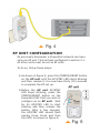
1
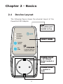
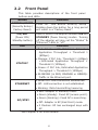
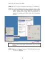
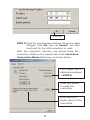
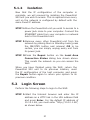
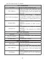
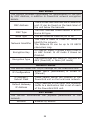
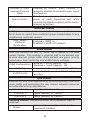
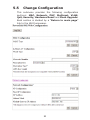
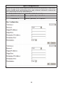
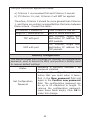
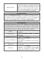
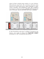
Powerline Ethernet Adapter User Manual EU type Introduction This user manual provides practical information for the installation, operation and application of the device. It is suitable for those with little or no networking experience, although some advanced topics are also covered. A glossary of acronyms is included in Appendix A for reference. Save Our Environment This symbol means that when the equipment has reached the end of its useful life, it must be taken to a recycling centre and processed separate from domestic waste. The cardboard box, the plastic contained in the packaging, and the parts that make up this device can be recycled in accordance with regionally established regulations. Never throw this electronic equipment out along with your household waste. You may be subject to penalties or sanctions under the law. Instead, ask for instructions from your municipal government on how to correctly dispose of it. Please be responsible and protect our environment. Copyright Copyright© 2008 Comtrend Corporation. All rights reserved. The information contained herein is proprietary to Comtrend Corporation. No part of this document may be translated, transcribed, or reproduced in any form or by any means without prior written permission of Comtrend Corporation. NOTE: This document is subject to change without notice. Table of Contents Chapter 1 - Introduction 2 Chapter 2 - Basics 3 2.1 Device Layout 3 2.2 Front Panel 4 2.3 Default Settings 5 Chapter 3 - Quick Setup 6 3.1 Internet Connection 6 3.2 Computer Connection 8 Chapter 4 - Network Performance 12 4.1 Point-to-Point Network 13 4.2 Point to Multipoint Network 14 4.3 Neighboring Networks 15 Chapter 5 - Web User Interface 5.1 IP Configuration 17 17 5.1.1 Fixed IP 17 5.1.2 Isolation 21 5.2 Login Screen 21 5.3 WUI homepage 22 5.4 Further Information 25 5.5 Change Configuration 30 Chapter 6 - HELP 38 6.1 Troubleshooting 38 6.2 FAQ 41 Appendix A - Acronyms 44 Chapter 1 - Introduction This user guide provides details concerning the installation, configuration and application of COMTREND Corporation’s PowerGrid 902 Powerline adapter. The PowerGrid 902 is the first of its kind to incorporate an AC filter with rear socket. It allows for the connection of the adapter to the electrical grid of a home without depriving the user of a single power outlet. The PowerGrid 902 is the physical link between Powerline and Ethernet (10/100M) networks. The design is such that, on the one hand, it avoids limiting a power socket to just PLC purposes, and on the other hand, provides a filtered power socket to avoid interference from appliances connected to it. The front panel of the PowerGrid 902 has two buttons and three LEDs that allow the user to configure a secure PLC network without the use of a computer. The Status LED shows the available level of data throughput in the application layer. SPECIAL FEATURES One Button Security Setup - Automatic generation of an Encryption Key and Network Identifier by pressing a single button! Throughput Indicator - A tri-color Status LED that shows estimated data throughput in the application layer Rear Socket with AC Filter - Plug the PowerGrid 902 into a power outlet without losing use of the outlet for other applications. Chapter 2 - Basics 2.1 Device Layout The following figure shows the physical layout of the PowerGrid 902 adapter. LAN the yellow port located on top AP/STBY ETHERNET STATUS FRONT PANEL CONFIG RESET ON STBY Powerline Ethernet Adapter with Filte r POWER OULET – AC Filtered Outlet located in front POWER PLUG – located in back 2.2 Front Panel This table provides descriptions of the front panel buttons and LEDs. Button Function CONFIG/RESET (Security Setup / Factory Reset) Press for “One Button Security Setup”. Holding down the button for a long period will result in a “Factory Reset”. ON/SBY (Power ON / Standby button) Used to switch the adapter between ON and STANDBY (Power Saving) modes. Turning off the adapter will also set the “Status” & “Ethernet” LEDs to “off” LED Function • Red: Adapter is ON. If PLC link, Estimated Application Throughput < Threshold 1 (6Mbps). STATUS* • Orange: if PLC link, Threshold 1 (6Mbps) < Estimated Application Throughput < Threshold 2 (12Mbps). • Green: if PLC link, Estimated Application Throughput > Threshold 2 (12Mbps) • BLINKING (in RED, ORANGE or GREEN): Traffic in the Ethernet port. • Green On: LAN connection established. ETHERNET • Off: LAN connection is not established. • Blinking: Data transmitting/receiving • Red: Adapter in Standby mode. • Green (steady): Fixed AP (access point). AP/STBY • Green (blinking): Fixed AP is searching. • Off: Adapter in EP (End Point) mode. • 3 Flashes: EP has exchanged keys with AP * see Chapter 4 for more details. 2.3 Default Settings The factory default settings are presented below. • Network Mode is AP (Public) • IP Configuration is Fixed IP • MAC Type is In-Home AV • Node type is End Point • Configuration password = paterna • Factory Reset password = betera • Fixed IP address = 10.10.1.69 • Fixed IP subnet mask = 255.255.0.0 • Default Gateway IP address = 192.168.1.105 NOTE: These configuration settings can be customized using a web browser. For further instructions, see Chapter 5 - Web User Interface. To return the adapter to factory default settings, follow the FACTORY RESET procedure in the Troubleshooting section of this manual. Chapter 3 - Quick Setup PowerGrid 902 units are configured by default with flexible network settings. As a result, when they are plugged into the power mains of a home they will connect to an already existing PowerGrid network. If there is no existing network they will create a new network that will operate smoothly but without enhanced security features. This is why it is recommended to reconfigure your PowerGrid 902 units to form a secure network (with a unique network identifier and encryption key). This can be accomplished using just the front panel buttons on the PowerGrid units. The following sections describe how to setup a secure network in this way. NOTE: You will need a single PowerGrid 902 unit and Ethernet cable for each computer, or other device, that you wish to connect to the Internet. 3.1 Internet Connection The steps below show how to connect a PowerGrid 902 unit to your modem. 1.Turn on your modem and wait for the Internet connection to become active. 2.Plug a PowerGrid 902 unit into the power socket closest to the modem as in figure 1 (at right). The Status LED on the front panel of the unit should light up RED. 3. As in figure 2, connect the PowerGrid 902 unit to the LAN port of the modem with an Ethernet cable. The ETHERNET LED on the unit should light up GREEN. 6 AP UNIT CONFIGURATION A PowerGrid network consists of one AP (Access Point) unit connected to multiple EP (End Point) units. The AP unit controls access to the Internet and connects the EP units to the network. Follow step 4 (below) to configure the AP unit. 4.As shown in figure 3, press the CONFIG/RESET button on the PowerGrid 902 unit. Wait for the AP/STBY LED to start blinking and then release it. Wait another thirty (30) seconds until it stops blinking and check the AP/STBY LED. If the AP/STBY LED is now ON, then setup was successful and you can now proceed to section 3.2, where you will configure the EP unit. If AP/STBY LED is now OFF, or just keeps blinking, you must first press the CONFIG/RESET button for 15 seconds to reset the unit and repeat step 4. After several attempts, if the AP/STBY LED does not stay ON, then disconnect the PowerGrid 902 unit from the modem and the power socket, choose another unit and repeat the process from step 2. If all else fails, contact your supplier or service provider for further assistance. 3.2 Computer Connection The steps below show how to connect a PowerGrid 902 unit to your computer. 1.Turn on your computer. 2.Plug a PowerGrid 902 unit into the power socket closest to the computer. The Status LED should light up RED, as in figure 1. 3.Connect the PowerGrid 902 to the computer with an Ethernet cable, see figure 3. The ETHERNET LED on the unit should light up GREEN. EP UNIT CONFIGURATION As previously discussed, a PowerGrid network can have only one AP unit. This unit was configured in section 3.1. All other units must be set as EP units. To do so, follow these steps: 4.As shown in figure 5, press the CONFIG/RESET button on the AP unit until the AP/STBY LED starts blinking and then release it. You now have thirty (30) seconds to complete the EP set up. 5.Before the AP unit AP/STBY LED stops blinking, press the CONFIG/RESET button on the PowerGrid 902 that you wish to configure as an EP unit. Wait for its AP/STBY LED to start blinking and then release the button. After a few seconds, the AP/STBY LED should flash quickly three times and then turn OFF, as shown in figure 6. If the AP/STBY LED of the EP unit is now OFF, then proceed to step 6. If the AP/STBY LED of the EP unit is now ON, or just keeps blinking, you must press CONFIG/RESET for 15 seconds and then return to step 4. After several tries, if the AP/STBY LED of the EP unit does not remain OFF, then disconnect it from its power socket and from the computer, or other device. Select another EP unit, if possible, and repeat the process from step 2. If all else fails, contact your supplier or service provider for further assistance. 6.After adding the EP unit to the PowerGrid network, check that the AP/STBY LED on the AP unit has stopped blinking and remains ON, as in figure 7. If the AP/STBY LED on the AP unit is now OFF, or just keeps blinking, you must first reset the unit and then try again. To reset the unit, press CONFIG/ RESET for 15 seconds. Then return to step 4 in section 3.1 and repeat section 3.2 for every device you wish to add to the network. After several tries, if the AP/STBY LED on 10 the AP unit does not stay ON, then disconnect it from the modem and its power socket, choose another unit to be the AP unit and repeat the entire process starting from section 3.1, step 2. If all else fails, contact your supplier for further assistance. 7.If the AP/STBY LED on the AP unit is now ON, then you have completed the setup successfully. CONGRATULATIONS! You can now either: Add another computer to the network by repeating steps 1-6 OR Stop here and start enjoying your secure PowerGrid network! NOTE: These PowerGrid 902 units keep their network security settings even after losing power, so that you don’t need to reset the network, when moving network devices or even after a power outage! 11 Chapter 4 - Network Performance The Status LED shows the estimated available level of throughput in the application layer. There are three levels of throughput indicated by three different LED colors. A particular adapter shows, with one color, the throughput level with reference to the adapter sending the most data to it. In the case of a network consisting of two adapters, they always show the level of throughput with reference to the other. However, in the case of a network of three or more adapters, each one internally measures the amount of bytes received from the other adapters in the network and only shows the level of throughput with reference to the one that is sending the most data. A throughput estimator also keeps track of the number of neighboring networks since available bandwidth will be divided between them when sharing the PLC channel. The thresholds for these levels of throughput are preconfigured in the system as shown below. LED STATUS RED Estimated Throughput < Threshold 1 (6Mbps) ORANGE Threshold 1 (6Mbps) < Estimated Throughput < Threshold 2 (12Mbps) GREEN Estimated Throughput > Threshold 2 (12Mbps) BLINKING (in any color) Traffic in the PLC port (for each estimated throughput level) 12 4.1 Point-to-Point Network • CASE 1: Estimated throughput is less than 6 Mbps. The PLC channel is not able to transmit an SDTV channel. The STATUS LED will be RED as shown in the following figure: Set Top Box video server data flow AP/STBY AP/STBY ETHERNET ETHERNET E STATUS STATUS S ST CONFIG RESE T ON STBY CONFIG RES ET ON STBY Powerline Ethernet Adapter with Filt er PLC adapter Powerline Ethernet Adapter with Filt er PLC adapter Status indicator blinking RED Estimated throughput < Mbps • CASE 2: Estimated throughput is greater than 6 Mbps but less than 12 Mbps. The PLC channel is able to transmit an SDTV channel, but not two SDTV channels simultaneously or one HDTV channel. The STATUS LED will be ORANGE as shown in the following figure: Set Top Box video server data flow AP/STBY AP/STBY ETHERNET E ETHERNET STATUS S ST STATUS CONFIG RES ET CONFIG RESE T ON STBY PLC adapter ON STBY Powerline Ethernet Adapter with Filt er PLC adapter Powerline Ethernet Adapter with Filt er Status indicator blinking ORANGE Mbps < Estimated throughput < Mbps • CASE 3: Estimated throughput is greater than 12 Mbps. The PLC channel is able to play at least two SDTV channels or 1 HDTV. The STATUS LED will be GREEN as shown here: 13 Set Top Box video server data flow AP/STBY ETHERNET AP/STBY ETHERNET E STATUS S ST STATUS CONFIG RES ET CONFIG RESE T ON STBY ON STBY Powerline Ethernet Adapter with Filt er PLC adapter Powerline Ethernet Adapter with Filt er PLC adapter Status indicator blinking GREEN Estimated throughput < Mbps 4.2 Point to Multipoint Network In the case where the PLC network is composed of three or more adapters, similar situations could arise as with a point-to-point network. These are illustrated in the following figures: video server Set Top Box Estimated throughput < Mbps data flow AP/STBY ETHERNET STATUS CONFIG RESE T ON STBY PLC adapter AP/STBY ETHERNET E STATUS S ST CONFIG RESE T ON STBY Powerline Ethernet Adapter with Filt er Powerline Ethernet Adapter with Filt er PLC adapter Status indicator blinking GREEN Mbps < Estimated throughput < Mbps Set Top Box data flow AP/STBY ETHERNET E STATUS S ST CONFIG RESE T ON STBY PLC adapter Powerline Ethernet Adapter with Filt er Status indicator blinking ORANGE The STATUS LED in each adapter will show the estimated level of the PLC link from which it is receiving the most amount of traffic at any given time. The status LED in PLC adapter 3, for example, could be showing a level of throughput available from PLC adapter 2 for a period of 14 time as illustrated in the figure above. However, traffic flow could change through user intervention and then the status LED in PLC adapter 3 could show the level with reference to the PLC adapter 1 link, as shown in the following figure. video server Set Top Box Estimated throughput > Mbps AP/STBY ETHERNET E STATUS S STA CONFIG RESE T ON STBY Powerline Ethernet Adapter with Filt er AP/STBY data flow ETHERNET E STATUS S ST CONFIG RESE T ON STBY Powerline Ethernet Adapter with Filt er Status indicator blinking GREEN PLC Status indicator blinking GREEN PLC adapter adapter Estimated throughput > Mbps data flow Set Top Box data flow Estimated throughput < Mbps AP/STBY ETHERNET E STATUS S STA CONFIG RESE T ON STBY PLC adapter Powerline Ethernet Adapter with Filt er Status indicator blinking RED 4.3 Neighboring Networks The Status LED also takes into account the possibility of having neighboring networks. In such a case, the throughput evaluator will divide the available bandwidth in two when there is visibility between any two networks since the PLC channel must be shared on a time basis. In the following figure, an example of an isolated network is first shown. 15 ISOLATED NETWORK Set Top Box video server data flow AP/STBY ETHERNET STATUS AP/STBY ETHERNET E STATUS S ST CONFIG RESE T CONFIG RESE T ON STBY ON STBY Powerline Ethernet Adapter with Filt er PLC adapter Powerline Ethernet Adapter with Filt er PLC adapter Status indicator blinking GREEN Estimated throughput = 0 Mbps In the next figure, the previous network (network 1) sees a new neighboring network (network 2), and a new evaluation of throughput is made to show the user that channel conditions have changed and available bandwidth has decreased: PLC NETWORK Set Top Box video server data flow AP/STBY ETHERNET AP/STBY ETHERNET E STATUS S ST STATUS CONFIG RESET CONFIG RESET ON STBY ON STBY Powerline Ethernet Adapter with Filter PLC adapter Powerline Ethernet Adapter with Filter PLC adapter Status indicator blinking ORANGE Estimated throughput = 0 Mbps / = 0 Mbps PLC NETWORK Set Top Box video server data flow AP/STBY AP/STBY ETHERNET E ETHERNET STATUS S ST STATUS CONFIG RESET CONFIG RESET ON STBY PLC adapter ON STBY Powerline Ethernet Adapter with Filter PLC adapter Powerline Ethernet Adapter with Filter Status indicator blinking GREEN Estimated throughput = 0 Mbps / = Mbps 16 Chapter 5 - Web User Interface The web-based user interface (WUI) provides information about your PowerGrid 902 units and can also be used to configure or reset their settings. The WUI is accessed using a web browser, such as Microsoft Internet Explorer. The instructions that follow assume the PowerGrid network has been configured correctly (i.e. according to the instructions in Chapter 3 or the QIG) and that the host computer is running Windows XP. NOTE: The process described in the following sections will work for any operating system (OS), but the specific steps will need to be adjusted to match your particular computing environment. 5.1 IP Configuration Before using the WUI, you first need to adjust the IP configuration of the host PC. This is a two-step process addressed in subsections 5.1.1 and 5.1.2. FYI: The IP configuration defines the location of your computer within the network using Internet Protocol (IP) addressing. Your computer needs an IP address so it can receive and send information on the network. In Fixed IP mode you assign this IP address yourself; while in DHCP mode it is assigned automatically by a DHCP server. 5.1.1 Fixed IP The following instructions describe how to change the IP configuration of your computer to FIXED IP mode, so 17 that you can access the WUI. STEP 1: Turn on your computer (and login, if necessary). STEP 2:F����������������������������������������������� rom the desktop (as shown below), click on the Start button and select Network Connections. Next, double-click Local Area Connections to open its window and then click the Properties button. NOTE: You may also access this window by doubleclicking the Local Area Connection icon on your taskbar. STEP 3:Select Internet Protocol (TCP/IP) and click the Properties button. �������� 18 STEP 4:Check the settings in the Internet Protocol (TCP/IP) Properties dialog box (shown on the far right in the figure above). Make sure to record all the settings you see here, as you will need to reset them later. STEP 5:If the “Obtain an IP address automatically” radio button is selected, then your PC is configured in DHCP mode. In this case you should select the “Use the following IP address” radio button instead. If it is not selected then your PC is already in FIXED IP mode. STEP 6:Change the IP address, Subnet Mask and Default Gateway to match those values shown in the figure below and click the OK button. 19 Click OK STEP 7:Close the previous two windows. Since you made changes, click OK, but not Cancel! You then must wait for the LAN connection to reset. After the connection recovers, you should check the connection status on the support tab of the Local Area Connection Status dialog box, as shown below. This shows the IP address as assigned in STEP 6. Press this button to repair the connection Look here for a status report of the connection. 20 5.1.2 Isolation Now that the IP configuration of the computer is complete, we will proceed by isolating the PowerGrid 902 unit you wish to access. This is required since every unit on the network is configured by default with the same Fixed IP address. STEP 1:Move the PowerGrid unit you wish to access to a power jack close to your computer. Connect the ETHERNET cable from your computer or network hub to this PowerGrid unit. STEP 2:Remove every other PowerGrid unit from the network by placing them in Standby mode (press the ON/STBY button and release) OR to be certain, you can simply unplug every unit from its power jack. STEP 3:Press the Repair button on the Local Area Connection Status dialog box shown above. This resets the network so you can access the WUI. When you have finished using the WUI, return the PowerGrid 902 unit to its previous location, reset the IP configuration of the host computer, and press the Repair button again to return your system to its previous condition. 5.2 Login Screen Perform the following steps to login to the WUI: STEP 1:Start the Internet browser and enter the IP address as a HTTP link in the URL address field and press Enter. For the default IP address of 10.10.1.69, you must enter “http://10.10.1.69”, as shown below. 21 STEP 2:The login screen should appear, as shown below. Enter the login password in top section and click OK to continue. To perform a factory reset on the device you must enter the factory reset password in the bottom section and click OK. The WUI login password and other default settings can be found in section 2.3 Default Settings. NOTE: You can change this password in the WUI (see section 5.5). 5.3 WUI homepage If login is successful, you will arrive at the WUI homepage. This screen provides summary information concerning the PowerGrid unit and its connections. It also provides access to the Further Information and Change Configuration screens. These screens are discussed in section 5.4 and section 5.5. 22 23 See the table below for details. PLC Connections PLC PORT The PLC data connection port MAC Address Phy Tx/Rx Throughput Bridge State Network Id This is a code that identifies each PowerGrid unit. It can be found on the back label of the unit below the barcode. Physical Transmission / Reception Throughput is a measure of network bandwidth. Available data transmission capacity is roughly half this value. Enabled indicates there is a data connection. Disabled indicates no data connection. The Network ID is used for network security. If present, the network is in FIXED AP mode. External Interfaces Interface Phy Throughput Bridge State EXTA = Ethernet Physical Throughput = Data Transmission Capacity Forwarding = Active General Information MAC Type MAC Address IP Address The MAC Address shown above is an In-Home AV type. This is a code that identifies each PowerGrid unit. It can be found on the back label of the unit below the barcode. The IP Address defines the location of the PowerGrid unit on the local area network. 24 Node Type This will show as Fixed AP, EP or AP. Number of Boots The number of times this PowerGrid unit has been rebooted since the last Factory Reset. NOTE: The remaining fields are advanced settings used for technical support. 5.4 Further Information This screen provides more detailed information concerning your network. It is divided into System Information followed by multiple Status sections: Mac, Network, PHY, Multicast, VLAN, QoS and Security. Each section is divided by a link back to the WUI homepage entitled “Return to main page”. 25 26 The tables below provide details about each section. Uptime Firmware Version System Information This shows the length of time the PowerGrid unit has been on. This shows the PowerGrid 902 installed firmware version 27 MAC Status This section provides information for identification of the unit by MAC Address, in addition to PowerGrid network encryption details. This is a code that identifies each PowerGrid MAC Address unit. It can be found on the back label of the unit below the barcode. The MAC Address shown above is an InMAC Type Home AV type. Node Type This will show as Fixed AP, EP or AP. This field is used in Fixed AP mode to identify the network. Network Identifier The Network ID can be up to 20 ASCII characters long. In Fixed AP mode, it shows a key in ASCII Encryption Key or HEX format. In AP mode it shows as Disabled. The possibilities are 3DES or 128/256 bit Encryption Type AES (Fixed AP) or None (AP mode) Network Status This section shows the TCP/IP settings for the PowerGrid unit. Either DHCP (Automated) or FIXED IP IP Configuration (Manual) IP Address / Subnet Mask These values define the location of the PowerGrid unit on the local area network. Default Gateway IP Address The IP address of the router that forwards traffic to a destination that is out of reach of the PowerGrid 902 unit. PHY Status This section summarizes the physical parameters of the network. Notches Enabled by default. 28 Wireless (27Mhz) keyboard/mouse notch Power Control Disabled by default. When Enabled, it prevents wireless keyboard/mouse signal interference. This function minimizes the transmission power of each PowerGrid unit while maintaining data throughput performance. Enabled by default. Multicast Status IGMP (Internet Group Membership Protocol) is a protocol used by IP hosts to report their multicast group memberships to any neighboring multicast routers. IGMP Aware Enabled = IGMP on Multicast Disabled = IGMP off (default) Syndication VLAN Status With this function an 802.1Q VLAN Tag is added to the data packet header. This enables a physical LAN to be divided into several discrete virtual LANs. Data packets are given priority based upon their VLAN Tag and VLAN Priority settings. Enabled = VLAN Tagging - On VLAN Configuration Disabled = VLAN Tagging - Off VLAN Tag A number in the range from 2 to 4094. A number between 0 and 7 (7 is highest VLAN Priority priority). QoS Status Improve the end-user experience by prioritizing audio, video and voice traffic and optimizing the way shared network resources are allocated among applications. Default Priority 2 is the default priority Criterion 1 None (default) or Custom Criterion 2 None (default) or Custom Security Status: Indicates whether WUI password login is required Password is currently installed / No Status password installed 29 5.5 Change Configuration This submenu provides the following configuration sections: MAC, Network, PHY, Multicast, VLAN, QoS, Security, Hardware Reset and Flash Upgrade. Each section is divided by a “Return to main page” link to the WUI homepage. 30 31 The tables below provide details about each configuration section. 32 MAC Configuration This section provides options to configure the PowerGrid unit MAC characteristics and network encryption mode. In-Home AV is the only option at this MAC Type time. There are 2 types of nodes, Fixed AP Node Type and EP. This field is used in Fixed AP mode to identify the network. Network Identifier The Network ID can be up to 20 ASCII characters long. This key, in either ASCII or HEX Encryption Key format, is used to encrypt the network. It is disabled in AP mode. You have the choice of 3DES or AES Encryption Type encryption. AES encryption can be set as 128 or AES Key Length 256 bit strength. NOTES:In 3DES mode, the Encryption Key can be up to 24 ASCII characters or 42 hexadecimal numbers. In AES mode, it can be up to 8 ASCII characters or 14 hexadecimal numbers (256 bit mode). Hexadecimal encryption is stronger. Network Configuration The section provides options to configure the IP configuration. IP Either DHCP (Automated) or FIXED IP Configuration (Manual). NOTE: In FIXED mode the IP Address, Subnet Mask and Default Gateway IP Address can be set manually, while in DHCP mode they are assigned by a server. Changes do not become effective until after a reboot of the PowerGrid 902 unit. These values define the location of IP Address / the PowerGrid unit on the local area Subnet Mask network. 33 Default Gateway IP Address The IP address of the router that forwards traffic to a destination that is out of reach of the PowerGrid 902 unit. PHY Configuration This section provides options to configure the physical parameters of the network Notches Enabled by default. Wireless (27Mhz) Enable this option when using a wirekeyboard/mouse less keyboard or mouse to avoid internotch ference. It is disabled by default. This function minimizes the transmission power of each PowerGrid unit while Power Control maintaining data throughput performance. Enabled by default. Multicast Configuration IGMP (Internet Group Membership Protocol) is a protocol used by IP hosts to report their multicast group memberships to any neighboring multicast routers. IGMP Aware Enabled = IGMP on Multicast Syndication Disabled = IGMP off (default) VLAN Configuration With this function an 802.1Q VLAN Tag is added to the data packet header. This enables a physical LAN to be divided into several discrete virtual LANs. Data packets are given priority based upon their VLAN Tag and VLAN Priority settings. Enabled = VLAN Tagging - On VLAN Configuration Disabled = VLAN Tagging - Off Choose a number in the range from 2 VLAN Tag to 4094. Choose from 0 to 7 with 7 being the VLAN Priority highest priority. 34 QoS Configuration Improve the end-user experience by prioritizing audio, video and voice traffic and optimizing the way shared network resources are allocated among applications. Default Priority 2 is the default priority Criterion 1 None (default) or Custom Criterion 2 None (default) or Custom If custom criteria are chosen, the following (previously hidden) fields will appear: 35 The QoS criteria are applied as follows: a) Criterion 1 is processed first and Criterion 2 second b) If Criterion 1 is met, Criterion 2 will NOT be applied Therefore, Criterion 2 should be more general than Criterion 1, and there are certain incompatibilities that arise between these criteria. Consult this table: If Criterion 1 Protocol is … Origin IP / Destination IP TCP with port UDP with port Then Criterion 2 can be … None of these protocols. UDP Protocol, Origin and destination IP address for UDP packets TCP Protocol, Origin and destination IP address for TCP packets Security Configuration This section allows you to change (or remove) the configuration password, used to access the WUI, and perform a factory reset to recover default settings Password is currently installed / No Status password installed To change the configuration password, notice that you must enter it twice; first in the New password field and again in the Confirm new password Set Configuration field. The configuration password can Password be up to 20 characters in length. To remove the configuration password, leave these fields empty. Click OK to make this change. 36 Factory Reset To reset the device to factory settings, enter the factory reset password (see section 2.3 Default Settings) and click OK. Use this function with caution, since, as noted onscreen, this will erase the current configuration settings. Hardware Reset Press the Hardware Reset button to reboot the device but not erase the configuration settings. It performs the same function as holding down the Config/Reset button on the front panel of the unit. You must perform a hardware reset of the device to change some settings, such as IP mode (DHCP/FIXED). Flash Upgrade This section provides a method to upgrade the flash memory in the PowerGrid unit from a server using FTP or TFTP protocol. The flash memory is divided into three sections: the firmware, a boot-loader and the factory settings. Each of these can be upgraded separately to provide for maximum flexibility. Reports the current status of the flash Status upgrade. Choose firmware, loader or factory Flash section settings Upgrade Protocol Choose FTP or TFTP Enter the IP address of the FTP or TFTP server. Server IP Address This will be provided by your service provider. FTP User and Enter the user name and password Password if required This is the filename of the flash upgrade. The firmware and loader Filename have .bin extensions, while factory settings are stored as .cfg files. 37 Chapter 6 - HELP This PowerGrid unit has been designed to be a reliable and easy-to-use home networking device. However, should you experience any problems, please refer to the troubleshooting and FAQ sections below to resolve your issue. 6.1 Troubleshooting FACTORY RESET To reset a unit to factory default settings, simply press the CONFIG/RESET button for 15 seconds. The adapter will reset its configuration to factory default settings and auto-reboot. If the reboot is successful, it will be configured in EP mode. If you reset the AP unit, you will need to repeat the entire network setup process described in Chapter 3. NETWORK SETUP 1.Converting an AP unit into an EP unit: c) Make sure the PowerGrid unit is plugged directly into the electrical outlet and that it is powered on. d) Do a factory reset (see the RESET PROCEDURE above). 2. Converting an EP unit into an AP unit: e) Make sure the PowerGrid unit is plugged directly into the electrical outlet and that it is powered on. f) Press CONFIG/RESET button until its AP/STBY LED starts blinking. g) Wait until configuration period finishes (30 seconds). At that point the adapter has been designated as a Fixed AP if its AP/STBY LED is GREEN. 38 3.There MUST only be one Fixed AP in a network. Verify that this is the case by examining the AP/STBY LED for all adapters. If there is more than one AP in the network, it means that the key exchange process has failed. h) Perform a factory reset on the adapter you do not wish to be designated as an AP (see step 1 above). i) Repeat the network configuration procedure again (see Chapter 3). j) If the configuration procedure fails again, it is possible the adapters are using different forms of encryption. For example, one might be using AES and the other 3DES. To eliminate this as a possibility, perform a factory reset on all adapters and repeat the configuration process. k) If configuration still fails, connect a PC to each adapter, and use the WUI tool to ensure that all PLC devices have the same network ID, encryption mode and key. If not, try to configure them in electrical outlets that are nearby to avoid a communications problem. Once configured, move the adapters to their final position and test connectivity again. l) If encryption mode is not the same in the two adapters, then the EP may not have the ability to set the AP encryption mode for regulation issues or because it is from an older generation when AES was not available. Try to put the AP in an encryption mode compatible with all PLC devices, such as 3DES encryption. 4. NETWORK performance If the network is performing slowly or not at all, try the following: 39 m)Check the ETHERNET LED on every PowerGrid 902 unit. n) If the ETHERNET LED on any unit is OFF, check that the PowerGrid unit is connected securely. The ETHERNET LED on every unit should be GREEN. o) Make sure that the settings of all your networked devices are correct. p) Next check the STATUS LED of every unit. If any unit has a RED STATUS LED, plug that unit into a different power outlet and wait for the STATUS LED color to change to ORANGE or GREEN. q) If the STATUS LED of any unit remains RED after moving it to another outlet, perform a factory reset on the unit as described above. r) If there is no change, perform a on every unit, starting with the will then need to reconfigure according to the instructions in factory reset AP unit. You the network Chapter 3 - Quick Setup . FYI: A PowerGrid unit with a GREEN STATUS LED supports a HDTV signal (>12 Mbps), while a unit showing ORANGE can support a SDTV signal (6-12 Mbps). NOTE: If the HDTV video bandwidth is lower than 12Mbps, it may be possible to stream the video with an ORANGE STATUS LED in some cases. FURTHER ASSISTANCE If this section has failed to resolve or address your issue, consult your local agent. 40 6.2 FAQ The following are frequently asked questions (FAQ) and answers. 1. Do PowerGrid units work with surge protected power strips? Basic power strips provide simple protection for a surge increase in voltage. More expensive models have this feature, but also include a filter which provides protection against EMI (Electromagnetic Interference) or RFI (Radio Frequency Interference). Every house has different wiring set ups, and it is impossible to say which anti-surge protectors will work with the PowerGrid 902 and which will not. Our test lab and user experience has shown that the more expensive strips with EMI/RFI filters are more likely to prevent the PowerGrid 902 working than the basic strips. The Status LED will show red if there is a problem. 2. What if I cannot fit my PowerGrid unit into my plug socket? Your PowerGrid units might not fit because the sockets are too close to the floor or are in the skirting board. The easiest way around this is to use a trailing power strip and plug the Adapter into the strip. Please make sure that the strip is not an anti-surge adapter strip, as per the previous point. 41 3.What if the flat next door has PowerGrid units as well? In this case, make sure to configure the units according to the procedure in this user manual. That way, each pair of PowerGrid units will have its own unique security key and your connection will be secure. 4.Is it safe to leave the PowerGrid units on all the time? PowerGrid units are CE certified and completely safe to leave plugged in all the time. They may become slightly warm in use - this is perfectly normal. However, you may wish to put them into standby mode when not in use. To do so, simply press the ON/STBY button and release. 5.How much power do PowerGrid units use? The Adapters use 5.0 Watts when in use and 1.8 Watts in standby. Prices vary between electricity suppliers, but on average, both Adapters running all the time would cost about 9.6p a month. 6.What is the best way to check that my PowerGrid units are working properly? Your PowerGrid units are set to work together as a pair, and should work perfectly out of the box. The best way to test them is to find a double plug socket, and plug them in next to each other. Often the best 42 place to find a double plug socket is in your kitchen. Alternatively plug them into a trailing extension strip (but not an anti-surge strip). When plugged in, after 10-40 seconds, the PowerGrid units will configure themselves so that each has a GREEN STATUS LED and one of the pair has an AP/STBY LED that is GREEN. If the PowerGrid units don’t configure themselves as above, you need to follow the FACTORY RESET procedure in the Troubleshooting section. 43 Appendix A - Acronyms The following is a list of acronyms referenced in this manual. Acronym 3DES AES AP DES EP HDTV Expanded Triple DES Advanced Encryption Standard Access Point Data Encryption Standard End Point High Definition TV ISP Internet Service Provider PC Personal Computer PLC Powerline Communications SDTV Standard Definition TV STB Set Top Box WUI Web User Interface 44 260072-014 PowerGrid 902 User Manual A2.0