1
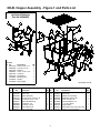
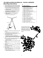
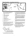
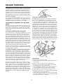
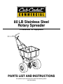
80 LB Stainless Steel
Rotary Spreader
Professional Turf Equipment
PARTS LIST AND INSTRUCTIONS
This product may be covered by one or more of the following patents:
4,511,090, Pending
80LB. Hopper Assembly - Figure 1 and Parts List
The Optional
Jet-Action Deflector
Part No. 02004523
2
2
7
4
14
9
1
12
8
4
5
12
1
7
3
4
7
13
18
15
17
6
11
7
5
19
2
16
Ref.
No.
1
2
3
4
5
6
7
8
9
Part
No.
00031168
00060036
00061066
00060057
00061052
00061053
01006254
01006305
01006308
9
Description
Screw, 1/4-20 x .75
Lock Nut, 1/4-20
Deflector
Screw, 1/4-20 x 7/8
Cotter Pin
Flat Washer
Mounting Tube
Handle
Ring Support
Qty.
2
3
1
1
1
1
1
1
1
10
7
8
8
3
6
GD: 02004175-T00
Ref.
No.
1
2
3
4
5
6
7
8
9
10
Part
No.
00005530
01010116
00030322
00031167
777D09015
00060027
00060033
00060036
00060043
00060044
Description
Nylon Flat Washer, 3/8
Screen, SS
Agitator Assembly
Hex Cap Screw, 1/4-20, 1.50
CCC Decal, 2-3/8 x 7-1/8
Agitator Shaft Bearing
Flat Washer, 1/4”
Nylock Nut, 1/4-20
Control Rate Knob
Control Arm Rate
Ref.
Qty. No
1 11
1
12
1
13
4
14
1
15
1
16
4
17
5
18
1
19
1
20
2
Part
No
01006772
00060046
00060049
00060050
00031168
00018628
01002048
02004176
01005631
01001251
Description
Control Plate Rate
Screen Clip
Agitator Arm Assembly
3/8 Retainer Spring Clip
Screw, 1/4-20 x .75
Nylon Flat Washer, 1/4
4” x 2” Vinyl Decal
Hopper Yellow
Index Washer Hex Screw, #8 x 3/8
Hopper Cover (not shown)
Qty.
1
2
1
1
1
2
1
1
2
1
80LB Frame Assembly - Figure 2 and Parts List
10
36
26
1
Operating Lever
Rod Assembly
(Ref. 39)
24
39
28
23
28
30
32
31
27
37
27
16
25
33
2
22
34
3
38
27
19
2
25
25
4
4
29
5
7
21
18
6
9
13
29
17
7
9
13
15
15
35
17
35
5
21
8
8
20
18
8
12
Ref.
No.
1
2
3
4
5
6
Part
No.
00010171
00018901
02004758
00030317
00030382
00030383
7
8
9
10
11
12
13
14
15
16
17
18
19
20
21
22
23
00030384
00030385
00030415
00030446
00030591
00030592
00030593
00030594
00030595
00031168
00060012
00060014
00060017
00060019
00060022
01005552
00060031
20
14
8
11
Description
Retainer Clip “C”
Drive Wheel
KIT, IMPELLER andGEAR SET
Impeller
Impeller Shaft
Axle
Gearset Oil Seal
Gearset Seal
Tap Screw
Handle Grip
Gearset Housing
Gearset Cover
Gearset Cap
Gearset Bevel Gear
Gearbox Pinion Gear
Hex Cap Screw, 1/4-20 x .75
Cotter Pin, 3/16 x 1-3/4
Collar Axle w/set screw Assembly
Flat Washer, .06, .776, 1.25
Roller Pin, 5/32 x 1-1
Roller Pin, 1/8 x 5/8
Hex Cap Screw, 1/4-20 x 2
Clevis Pin, 1/4 x 1/2
12
Qty.
1
2
1
1
1
1
1
2
3
2
1
1
1
1
1
4
2
2
6
1
1
4
1
Ref.
No
24
25
26
27
28
29
30
31
32
33
34
35
36
37
38
39
3
Part
No
00060032
01006129
01006128
00060078
00018963
00060034
00060036
00031167
00060069
00060071
00060072
00060073
00060080
00020913
00060017
01000129
01004875
01005637
01004876
01005640
01004878
01005643
01006035
14
11
GD: 01004977-P05
Description
Cotter PIn, 3/32 x 1
FRAME/BEARING ASSEMBLY, SS
FRAME/BARING ASSEMBLY, EPOXY
GREASE FITTING, 1/4-28 X 3/16
PLASTIC AXLE BEARING
Operating Lever, Rubber Handle
Assembly
Lock Nut Nylon Insert, 1/4-20
Hex Cap Screw, 14-20 x 1.5
Roller Pin, 1/8 x 7/8
Hex Lock Nut, 5/16
Nut, Nylon Insert, 5/16-18
Lock Washer, 5/16
Plastic Plug, Epoxy
Plastic Plug, SS
Flat Washer, 1.25 x .776 x .062 SS
Washer Hex Screw
Handle Assembly, SS
Handle Assembly, Epoxy
Lower Handle, SS
Lower Handle, Epoxy
Support Leg, SS
Support Leg, Epoxy
Operating Rod Lever
Qty.
1
1
1
2
4
1
12
4
1
1
1
1
2
2
4
6
1
1
1
1
1
1
1
Shut-Off Assembly - Figure 3 and Parts List
9
4
6
11
5
12
2
14
7
3
1
10
8
10
Ref.
No.
1
2
3
4
5
6
7
Part
No.
01006825
00020492
01009945
00060033
00060036
00060060
00060061
Description
Shut-off Plate
Slide Lever
Cotter Pin, 3/32 x 1/2 Lg
Flat Washer, 1/4”
Nylock Nut, 1/4-20
Pivot Lever Assembly
Pivot Lever Rod
13
Qty.
1
1
1
1
2
1
1
Ref.
No
8
9
10
11
12
13
14
4
Part
No
01004186
01004539
01004955
01004956
01005630
01005631
01005632
GD: 01005667-P02
Description
Spring Clip
Two Hole Weldment Plate
Plate Shut-off Clip
Plate Shut-off Spring
Flat Washer
Index Washer Hex Screw, 8 x 3/8
Index Washer Hex Screw, 8 x 5/8
Qty.
1
1
2
1
1
2
1
The Optional Remote Deflector - Part No. 02004519
Mounting Instructions
Ref.
No.
1
2
3
4
5
6
7
8
9
10
11
12
13
14
15
16
17
18
19
20
21
22
23
1.
Install the deflector tube mount (ref. 20) onto the right
side of the spreader frame (from the inside) as shown.
2. Install the tube bracket mount (ref. 19) to the right side
of the frame using appropriate hardware as shown.
a. Install 1/4-20 x 2 (ref. 5) through frame plate using
spacer (ref. 3), washer (ref. 6), and tighten using
1/4-20 nut (ref. 10).
b. Install nylon washer (ref. 2), bracket mount (ref. 19)
nylon washer (ref. 2) and tighten nut (ref. 8) until
bracket mount (ref. 19) easily turns.
3. Install offset bracket (ref. 4) onto deflector (ref.16)
a. Slide Long end of offset bracket into slot on
deflector (ref. 16)
b. Install 1/4-20 screw (ref. 9) and tighten sub
assembly using 1/4-20 nut (ref. 8)
Drill 9/32" Hole
Part No.
00010171
00018628
00030503
00035030
00060029
00060033
00060034
00060036
00060057
00060059
00060071
00060072
00060073
00061052
00061053
00061066
01006251
01006252
01006253
01006254
00030418
00031168
00060047
Description
Qty.
Retainer “C” Clip
1
Nylon Washer, 1/4
6
Deflector Arm Mount Spacer
1
Offset Bracket Deflector
1
Machine Screw, 1/4-20x2
1
Flat Washer, 1/4”
1
Operating Lever and Rubber
1
Lock Nut, Nylon Insert, 1/4
8
Machine Screw Pan Head, 1/4-20x7/8 5
Hex Nut, 1/4-20
2
Hex Lock Nut, 5/16-18
1
Nut, Nylon Insert, 5/16-18
1
Lock Washer, 5/16
1
Cotter Pin, 1/8 x 1
1
Flat Washer, 3/8
1
Deflector Tube, Plastic Only
1
Deflector Actuator Rod
1
Lever Rod Deflector Bracket
1
Tube Bracket Mount, Lever, Deflector
1
Deflector Tube Mount
1
Remote Bracket
1
HHCS, 1/4-20 x .75, SS
3
Machine Screw, 1/4-20 x 1.50, SS
1
9.5
Right Handle
4.
Slide deflector subassembly onto deflector tube mount
(ref. 20)
a. Install washer (ref. 15) onto deflector tube mount
and lock in place using cotter pin (ref. 14)
5. Fasten offset bracket (ref. 4) to bracket mount (ref. 19)
using appropriate hardware.
a. Install 1/4-20 screw (ref. 9) and tighten sub
assembly using 1/4-20 nut (ref. 8) until deflector (ref.
16) moves easily on deflector tube mount (ref. 20)
6. Install lever rod bracket (ref. 18) to bracket mount (ref.
19).
a. Install, making sure small flange of lever rod bracket
faces to the inside of the spreader, using
appropriate hardware.
7. Install remote bracket (ref. 21) onto right side of upper
handle.
a. Install using one 1/4-20 (ref. 23) and one 1/4-20 nut
(ref. 8)
8. Install operating lever (ref. 7) using appropriate
hardware
9. Install rod (ref. 17) into operating lever (ref. 7) and into
lever rod bracket (ref. 18)
10. Slide deflector up toward the bottom of the hopper as
far as it will go.
11. Place the operating lever (ref. 7) in the “OFF” position
and adjust the lock nut (ref. 11) so it is down against
the lever rod bracket (ref. 18).
a. Tighten nylock nut (ref. 12) up against the underside
of the lever rod bracket (ref. 18)
23
NOTE: Adjust the friction at the
three deflector arm pivot points
by tightening the nuts and then
backing them off 1/8th turn. Adjust the friction at the operating
lever pivot so that it will hold its
position.
9 or
21
2
22
22
20
17
8
10
14
12
9
11
6
5
3
13
2
18
9
8
2
19
2
9
8
4
16
1
7
10
5
8
8
15
8
The Optional Remote 3rd Hole Slide - Part No. 02004521
Mounting Instructions
Parts List
1. Mount the dual lever bracket (Ref. 1) to the right
handle using one machine screw (Ref. 2), one flat
washer (Ref. 3) and one hex nut (Ref. 4) as shown
below.
2. Mount the dual remote lever (Ref. 5) to the dual
lever bracket (Ref. 1) using one machine screw
(Ref. 6), two nylon flat washers (Ref. 7) and one
hex nut (Ref. 4) as shown below.
3. Slide the control cable (Ref. 8) through the hole in
the dual remote lever and the cable housing into
the fork of the dual lever bracket and pinch the
forks around the cable groove.
4. With the dual remote lever pushed all the way
forward attach the other end of the control cable to
the hole in the 3rd hole slide. Push the slide fully
closed and mount the cable housing to the shut off
plate using the cable clamp (Ref. 9), two machine
screws (Ref. 10), two lock washers (Ref. 11) and
two hex nuts (Ref. 12) as shown below.
5. Work the dual remote lever back and forth to be
sure that you are getting the full open and full
closed positions of the 3rd hole slide. If not, loosen
the cable clamp and adjust the cable.
Ref.
No.
1
2
3
4
5
6
7
8
9
10
11
12
13
Part No. Description
00030418
00060047
00060033
00060036
00030416
00060057
00018628
00030450
00020511
00031686
00060083
00060056
00060054
00020491
00020492
Impeller Shaft Support
Bottom of Hopper
13
6
Bracket, Dual Lever
Machine Screw
Flat Washer 1/4
Hex Nut, 1/4-20 Nylock
Lever, Dual Remote
Machine Screw
Flat Washer, 1/4 Nylon
Control Cable
Cable Clamp
Machine Screw
Lock Washer #8
Hex Nut, #8-32
Shut off Plate Assembly
Remote Shut off Plate
Slide Lever
Qty.
1
1
1
2
1
1
2
1
1
2
2
2
1
1
1
Rotary Spreaders - Assembly Instructions
Leg
On/Off Lever
Lower
Handle
Handle Grips
Handle
Hopper and Frame
1. Remove the spreader components from the
carton. You should find all of the parts shown
above plus the Hardware Package. The
Hardware Package contains:
1
1
1
1
1
1
1
1
1
4
4
4
12
Operating Lever
Rod
screws, 1/4-20 x 1 1/2 and 4 nylock nuts, 1/4-20.
5. Fasten the on/off lever to the handle's bracket
lugs using the clevis pin in the bottom hole of the
lever. Insert the clevis pin from left to right, facing
the rear of the hopper. Lock with the 3/32 x 1/2
cotter pin.
6. Attach the operating lever rod to the pivot lever
assembly at the bottom-rear of the hopper. First
screw the 5/16 hex nut on the threaded end of
the operating lever rod, add the 5/16 lock
washer, then insert the rod through the hole in
the pivot lever assembly and install the 5/16
locknut.
7. Attach the operating lever rod to the on/off lever
by inserting the bent end of the rod into the top
hole of the lever from left to right and install the
C-clip.
8. Pull the on/off lever to the off position and move
the shutoff plate assembly to the fully closed
position by adjusting the 5/16 hex nuts on the
bottom of the operating lever rod.
9. Place the handle grips on the handles.
10. Grease the axle bearings and the gear support.
11. Read the Spreader Calibration instructions
packed with your spreader and calibrate
following the instructions.
C-Clip
Calibration Gauge (ODD)
Calibration Gauge (EVEN)
Calibration Gauge Chain
Clevis Pin, 1/4 x 1/2
Cotter Pin, 3/32 x 1
Hex Nut, 5/16-18
Hex Nut, 5/16-18, Nylock
Lock Washer, 5/16
Hex Head Machine Screw, 1/4-20 x 2”
Machine Screw, 1/4-20 x 1-1/2"
Hex Screw, 1/4-20 x 3/4”
Nylock Nut, 1/4-20
2. Install the leg to the hopper and frame assembly
by fastening with 4 hex head machine screws,
1/4-20 x 2 and 4 locknuts, 1/4-20.
3. Attach the lower handle to the frame (with the “V”
section of the closed section of the handle facing
down) using 4 hex head screws, 1/4-20 x 3/4,
and 4 nylock nuts, 1/4-20. nuts, 1/4-20.
4. Attach the upper handle to the lower handle (with
the on/off bracket lugs facing up) using 4 machine
7
Spreader Calibration
Two items must be considered when calibrating a spreader. The first
is the distribution pattern of the spreader. That is, the pattern the product makes as it strikes the ground after being thrown out by the
spreader's impeller. There are many factors which affect the distribution pattern of a rotary spreader and some of them relate directly to
the product. For this reason, we recommend that the spreader be calibrated separately for every product to be applied. Spreader calibration should be checked at least once a month, or more often when the
spreader is used frequently.
TO USE THE CALIBRATION GAUGES:
The second item is the product application rate, that is the amount of
product applied per thousand square feet. This is important because
over-application can be costly and may cause plant injury, while under-application will reduce the effectiveness of the product.
The Calibration Gauges provide a series of "steps", numbered in 1/
32-inch increments, that will allow you to "fine-tune" the spreader.
Once you have calibrated your rotary spreader for the product chosen, open the operating lever and insert the calibration gauges until
you determine which step fits tightly into one of the open holes in the
hopper bottom. Record that step number for future reference when
using that product. You may choose to set other rotary spreaders for
application of the same product by adjusting the shut off plate to that
calibration gauge step. This will provide consistent settings for all of
your spreaders. To recalibrate your rotary spreader after a period of
use, adjust the rate control arm to the "24" position. Open the operating lever and insert the even-numbered Calibration Gauge into one of
the open holes in the hopper bottom. Close the operating lever and let
the shut off plate on the underside of the hopper make contact with
the number 10 step on the Calibration Gauge. Move the rate control
arm back toward the "6" position until the bottom of the arm makes
contact with the shut off plate. If your spreader is properly adjusted,
the top of the rate control arm should be at setting "10". To correct
variances, remove the rate control arm, place the bottom of the arm
(up to the bolt hole) in a vise, and bend either to the right or the left.
TO CALIBRATE A SPREADER, FOLLOW THESE
STEPS:
Check the spreader discharge holes with the operating lever in the
closed position. If the discharge holes are not fully closed, thread the
upper jam nut on the operating lever rod further up the rod. Tighten
the lower locknut and recheck. Repeat this procedure until the holes
are fully closed.
TO ACHIEVE A UNIFORM DISTRIBUTION PATTERN:
The accurate method for checking pattern uniformity is to lay out shallow boxes or pans in a row on a line perpendicular to the direction of
spreader travel. Eleven boxes or pans, two inches high placed on
one-foot centers will provide accurate calibration. To conduct the test,
begin with the pattern slide completely open and set the rate control
arm at the suggested approximate setting. Make three passes over
the boxes, pushing the spreader in the same direction each time. The
product caught in each box is then evaluated to determine the distribution pattern. Weighing the product in each box is the most accurate,
but a simpler method is to pour the contents of each box into a separate small vial or bottle. Then set the eleven vials or bottles side-byside in order. This makes the pattern variation quite visible.
To reduce the amount of discharge to the right side (operator's right)
the pattern slide should be partially closed and the test repeated until
the distribution pattern is uniform.
TO ACHIEVE THE CORRECT PRODUCT APPLICATION RATE:
The approximate spreader settings printed on any product label
should only be used as the initial setting for calibration. Set the rate
control arm at this approximate setting. Using the collection boxes or
pans, make a single pass over them to determine the effective pattern
width. The effective pattern width is twice (2x) the distance to the point
where the rate drops to one-half the average rate at the center. Example: If the product in the vials from the center boxes averages two
inches in depth, count out to the vial which has one inch of product. If
this is the fifth vial from the center and the boxes were on one-foot
centers, the effective pattern width is ten feet (2 x 5 ft.).
SPREADER TIPS:
1. Always push the spreader; do not pull.
2. Push the spreader at a consistent speed (approximately 3 m.p.h. is
recommended).
Knowing the effective pattern width (ten feet), measure out a lineal
distance to equal 1,000 sq. ft. (10 ft. x 100 ft. = 1,000 sq. ft.). Weigh
20 lbs. of product and place it in the spreader hopper and spread it
over the distance necessary to equal 1,000 sq. ft. (100 ft.). Then
weigh the product left in the hopper and subtract this amount from the
amount with which you started. The result is the application rate for
this product in pounds per 1,000 sq. ft. that your spreader is currently
adjusted to disperse. Adjust the rate control arm up or down as needed and repeat this procedure until the correct application rate is
achieved.
3. Always close the operating lever before filling the hopper.
4. Be sure the screen is in place to prevent lumps or paper scraps
from plugging the holes in the hopper bottom.
5. Always start walking forward before opening the operating lever;
close the operating lever before forward motion is stopped.
6. Hold the handle at a height that will keep the impeller level.
7. Empty the spreader after each use. Wash the spreader thoroughly
and allow it to dry. Keep the impeller clean.
8. Lubricate all moving parts. Apply grease to the five grease fittings;
two in the axle supports, two in the gear support and one in the idler
wheel (if the idler wheel has a steel hub).
8
Act of 1977 and the Occupational Safety and Health Act of 1970,
tests, approves, and certifies respiratory equipment as being safe
for its intended purpose.
General Requirements-Personal Protective
Equipment:
OSHA Standard 1910.132 through 1910.139
Note: Always be certain that the NIOSH compliance number is
on the product before purchasing respiratory equipment.
OSHA standard 1910.132 states in relevant part:
a. Protective equipment, including personal
protective equipment (PPE) for eyes, face,
head, and extremities, protective clothing,
respiratory devices, and protective shields and
barriers, shall be provided, used, and
maintained in a sanitary and reliable condition
whereever it is necessary by reason of
hazards of processes or environment,
chemical hazards, radiological hazards, or
mechanical irritants encountered in a manner
capable of causing injury or impairment in the
function of any part of the body through
absortion, inhalation or physical contact.
Two systems of respiratory protection are available, depending
on the type of respiratory risk involved: air-purification (filtering)
and air-supplying. For most pesticide work, the air-purifying
equipment is adequate and safe.
Protective equipment is usually required by the pesticide label in
one form or another and is integral to safe pesticide application.
Chemical-protective clothing consists of multilayered garments
made out of various materials that protect against a variety of
hazards. Because no single material can protect against all chemicals, multiple layers of various materials usually are used to increase the degree of protection. Protection is maximized by total
encapsulation (completely covering the wearer). An assortment
of types of chemical-protective hats, hoods, gloves, and boot covers are used with the garments.
This standard is subject to change. Please check www.osha.gov
for the latest regulatory updates
General
There are many brands and models of protective equipment
available for use in pesticide application. Price is not always an
indicator of quality, so shop carefully.
Sometimes, it is not possible to reduce a hazard by eliminating it,
substituting a less hazardous process or product, making changes
to equipment, or even by changing how you do the job. That’s
when you need personal protection.
Note: Select equipment that is NIOSH tested and approved.
PPE includes items like gloves, goggles, boots, hearing protection
and respirators. Respirators filter out particles or block gases and
vapors that can harm the respiratory system. With a surface area
well supplied with blood vessels and equal in size to a tennis court,
the lungs are the quickest and most direct route for absorbing
harmful substance into your body.
Protective equipment, appropriate for the task and hazards that an
employee could be exposed, shall be provided by the employer.
Since comfort and proper fit must be considered, the person who
is going to use it must select the proper size to ensure correct fit
and function. Unused protective equipment does not help anyone.
Note: PPE does not prevent accidents, but it does prevent or reduce injury and even fatalities when used properly.
Note: Many supply centers, hardware stores, chemical retailers,
and equipment/machinery dealers keep protective equipment in
stock.
Equipment (PPE)
Training
Protective equipment must be selected carefully. Always test fit
the protective equipment to be sure it fits properly and comfortably. If it isn’t comfortable -- it won’t be worn; if it isn’t worn -- it
won’t protect. PPE includes:
• gloves
Written procedures shall be developed for PPE use. These procedures shall include all information and guidance necessary for
their proper selection, use and care. The employer shall provide
fitting instructions including demonstrations and practice in how
the PPE should be worn, It is essential that both supervisors and
workers be properly instructed in PPE selection, use, and maintenance. Training shall provide the workers an opportunity to handle PPE, and have it fitted properly.
• safety goggles and glasses
When to replace PPE
• hard hats
All PPE shall be inspected routinely before and after each use. A
program for maintenance and care of PPE shall be initiated and be
adjusted to the type of work place, working conditions, and hazards. It shall include the following:
• respirators
• chemical-resistant clothing
• hearing protectors
• sensors to detect hazardous substance
• communication devices used for safe
deployment of workers
• inspection for defects and damage
Inhaling pesticide fumes and mists is a very common entry route
of pesticides into the body. Absortion through the lungs is great
and the sensitivity is high.
• cleaning and disinfecting
• repair
• storage
The National Institute for Occupational Safety and Health
(NIOSH), under authority of the Federal Mine Safety and Health
9
Many factors influence how long PPE (especially respirators) remains effective. As well as hours of use, an air-purifying respirator’s service life is affected by the concentration of dust and other
contaminants in the enviroment; the user’s body size; how strenuously the user works while the respirator is worn; and how the respirator is stored.
Note: As a result, it’s not possible to specify a length of time after
which a respirator should be replaced.
In general, replace a mask or filter when it is visibly dirty or damaged, or when you experience difficulty breathing through it. Replace respirator cartridges when you can smell or taste chemical
while or after using the respirator, or according to the manufacturer’s recommendations. Replacement or repairs shall be done only
by experienced person with parts designed for the PPE. No attempts shall be made to replace components or to make adjustments or repairs beyond the manufacturer’s recommendations.
10
Notes
11
MANUFACTURER’S LIMITED WARRANTY FOR CUB CADET COMMERCIAL
LAWN APPLICATION EQUIPMENT
IMPORTANT: To obtain warranty coverage owner may be required
present proof of purchase and applicable maintenance records to the
servicing dealer. Please see the operator’s manual for information on
required maintenance and service intervals. In addition, Cub Cadet
may deny warranty coverage if the hour meter, or any part thereof, is
altered, modified, disconnected or otherwise tampered with.
The limited warranty set forth below is given by Cub Cadet LLC with
respect to new merchandise used for commercial and related purposes
purchased and used in the United States and/or its territories and
possessions, and by MTD Products Limited with respect to new
merchandise purchased and used in Canada and/or its territories and
possessions (either entity respectively, “Cub Cadet”).
Cub Cadet warrants this product (excluding its No-Fault Components,
as described below) against defects in material and workmanship for a
period of one (1) year from the date of original retail purchase or lease
and will, at its option, repair or replace, free of charge, any part found
to be defective in materials or workmanship.
No-Fault Components include only belts, tires, and seats which are
warranted to be free from defects in material and workmanship for a
period of thirty (30) days from the date of original purchase or lease.
HOW TO OBTAIN SERVICE: Warranty service is available, WITH
PROOF OF PURCHASE AND APPLICABLE MAINTAINCE
RECORDS, through your local authorized service dealer. To locate the
dealer in your area;
In the U.S.A.:
Check your Yellow Pages, or contact Cub Cadet LLC at P.O. Box
361131, Cleveland, Ohio 44136-0019, or call 1-877-282- 8684, or log
on to our Web site at www.cubcadetcommercial.com.
In Canada:
For all provinces excluding Quebec contact Modern Power Products
d/o MTD Canada Ltd. At 60 Ottawa Street South, Kitchener, Ontario
N2G 3S7 or call 1-800-567-6775 or log on to our website at
www.cubcadet.ca.
In Quebec contact Les Distributions RVI Ltee. d/o MTD Canada Ltd.
2955 jean-Baptiste Deschamps, Ville Lachine, Quebec H8T 1C5 or
call 1-800-361-5770 or log on to our website at www.cubcadet.info.
This limited warranty does not provide coverage in the following cases:
a.
Routine maintenance items such as lubricants, filters, tuneups, brake adjustments, clutch adjustments, control linkages,
drive system, engines, and normal deterioration of the exterior
finish due to use or exposure.
b.
Service completed by someone other than an authorized
service dealer.
c.
For products sold or exported outside of the United States
and/or Canada, and their respective possessions and
territories, except those sold through Cub Cadet’s authorized
channels of export distribution.
d.
Damage or failure resulting from the use of defective or
improper peplacement parts and\or accessories other than
genuine Cub Cadet parts.
e.
Transportation charges and service calls.
f.
Failure to operate and maintain the product in accordance with
the Operator’s Manual furnished with the product,
g.
Damages and failures resulting from misuse, abuse, neglect,
accident, improper maintenance, alteration, vandalism, theft,
fire, water, or damage because of other peril or natural
disaster.
There are no implied warranties, including without limitation any
implied warranty of merchantability or fitness for a particular
purpose. No warranties shall apply after the applicable period of
express written warranty above. No other express warranties
beyond those mentioned above, given by any person or entity,
including a dealer or retailer, with respect to any product, shall
bind Cub Cadet. The exclusive remedy is repair or replacement
of the product as set forth above. The terms of this warranty
provide the sole and exclusive remedy arising from the sale
and/or lease of the products covered hereby. Cub Cadet shall not
be liable for any incidental or consequential loss or damage
including, without limitation, expenses incurred for substitute or
replacement lawn care services or for rental expenses to
temporarily replace a warranted product.
Some jurisdictions do not allow the exclusion or limitation of incidental
or consequential damages, or limitations on how long an implied
warranty lasts, so the above exclusions or limitations may not apply to
you. This limited warranty gives you specific legal rights, and you may
also have other rights that vary in different jurisdictions.
In no event shall recovery of any kind be greater than the amount of
the purchase price of the product sold. Alteration of safety features
of the product shall void this warranty. You assume the risk and
liability for loss, damage, or injury to you and your property and/or to
others and their property arising out of improper use, misuse or
inability to use the product. This limited warranty shall not extend to
anyone other than the original purchaser/Leasee or to the person for
whom it was purchased or leased as a gift.
Cub Cadet LLC - P.O. Box 361131, Cleveland, Ohio 44136-0019; Phone 1-877-282-8684
Form No. 02004269 Rev. 08-1 04/14/2008