1
321QE & 481QE AMPLIFIER OWNER’S MANUAL
(MODE D’EMPLOI)
877 COUSTIC
COUSTIC.COM
COUSTIC.COM
WELCOME
FEATURES
. . . to the Coustic world of power and clarity. These new Coustic 321QE and 481QE 4-channel
power amplifiers deliver the cleanest music you’ve ever heard at any power level in the 12-volt
environment.
Besides their sleek contoured design, the new 321QE/481QE power amplifiers offer the latest
and most sophisticated audio features. This manual offers you a guided tour of all these exciting
features. For the best sonic reproduction, please follow the installation suggestions and recommendations as closely as possible. The time you spend will prove to be worthwhile when you sit back
and enjoy the high fidelity music!
To further explore the potential of your Coustic amplifier, we recommend you match it with our
dynamic full-range speakers or subwoofers and electronic crossovers.
Whatever you need for your ultimate car audio system, look to Coustic - for a wide range of car
audio components to meet the most critical demands.
BUILT-IN ELECTRONIC CROSSOVER WITH CONTINUOUSLY ADJUSTABLE
CROSSOVER FREQUENCIES
An electronic crossover has many advantages over passive crossovers - lower cost, simplified yet
more flexible system design, lower distortion and higher gain structure. The 321/481QE power
amplifiers are equipped with built-in 18dB per octave continuously adjustable electronic
crossovers. The front and rear channels can be configured separately for full-range, high-pass or
low-pass applications.
OVER-CURRENT, SHORT CIRCUIT AND DC OFFSET PROTECTION
The sophisticated circuitry monitors abnormal conditions such as voltage spikes, oscillation, DC offset or short circuit. When any of these undesirable conditions exceed their respective preset limits,
the circuit will shut down the audio system briefly and lights up the protection indicator to identify
the problem for immediate attention. Once the problem is resolved, the amplifier will resume operation automatically.
HIGH SPEED HIGH CURRENT MOSFET SWITCHING POWER SUPPLY
Coustic . . . a sound investment.
High current MOSFET transistors are used in the power supply section to minimize internal heat
and maximize reliability. Furthermore, the combination of the very high pulse-width-modulated
(PWM) switching frequency and the extra large filter capacitance guarantees stronger and deeper
transient bass response.
TRIPLE DARLINGTON HIGH CURRENT/HIGH VOLTAGE FULLY COMPLEMENTARY
OUTPUT STAGE
Complementary output stage audio circuitry has long been a hallmark of "exotic" home amplifier
design. Coustic is one of the very few car audio manufacturers to incorporate such elaborate
audio circuitry into its power amplifiers. Triple Darlington configuration ensures the audio amplifier
is always operating at its optimum conditions.
LINE OUPTUTS
The full-range line outputs can be used to feed signals to another amplifier for your future expansion or for setting up a more sophisticated system.
No part of this publication may be reproduced, stored in a retrieval system or transmitted, in any
form or by any means, electronically, mechanically, or otherwise, without the prior written permission of Coustic or Mitek Corporation.
Please take a moment to register your purchase on line @ coustic.com.
Please also record the serial number of your amplifier in the space provided below and keep this
manual for future reference, as well as your sales receipt as proof of ownership. (The serial number of your amplifier is marked on the bottom of its metal chassis.)
Serial Number:
Date of Purchase:
WIDE RANGE INPUT SENSITIVITY ADJUSTMENT
The input sensitivity level of the Coustic 321/481QE amplifiers can be easily varied from as low
as 100 mV to as high as 5.0 volts by adjusting the control on the Input Panel.
LINE LEVEL AND SPEAKER LEVEL INPUTS
These ampliifers feature pre-amp inputs for use with head units that have RCA or line level outputs.
These amplifiers also feature speaker level inputs allowing the amplifier to work with head units
that do not have RCA or line level outputs. The audio signal can be obtained by simply connecting the amplifiers speaker level input wires to the head units speaker level outputs wires. If you are
using a floating or common ground car radio, this amplifier is the best fit for your system. It is compatible with floating or common ground car radio speaker outputs even without a floating ground
adapter.
ADJUSTABLE BASS BOOST
This feature allows you to enhance the bass performance of your sound system. The control is continuously variable with a maximum boost level of 18dB.
REMOTE SUBWOOFER GAIN CONTROL PORT (R S)
The 481QE amplifier has a built-in remote subwoofer level control input port. With the optional
R S remote control, the subwoofer output level can be adjusted to compensate for bass fluctuations
in a moving vehicle.
MULTI-FUNCTION PROTECTION INDICATOR
When the red protect indicator lights up it signifies a high operating temperature is detected and
the amplifier is temporarily shut down to allow for a cooling period. As soon as the temperature
returns to a safe level, the amplifier will restart and resume normal operation.
This indicator also lights up when the amplifier detects either an over-current situation, shorted
speaker outputs or a DC offset at the outputs. Turn off the amplifier, double-check all inputs and
speaker connections to make sure there is no short or inappropriate inputs. If all connections are in
order, turn on the amplifier to resume operation.
3
COUSTIC.COM
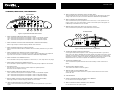
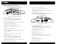
CONTROLS, INDICATORS, AND TERMINALS
INPUT PANEL
7
5 12
1
2
FRONT
9
FRONT
INPUT
OUTPUT
8
REAR
MODE
60
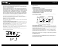
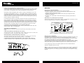
11. REAR CHANNEL INPUT SENSITIVITY LEVEL CONTROL (SENS)
The input sensitivity level can be varied from 5.0 volts to 100 mV depending on the output
voltage of the source unit (refer to sub-section titled INPUT SENSITIVITY ADJUSTMENT).
REAR
MODE
FREQ
180
HPF OFF LPF
60
FREQ
180
HPF OFF LPF
L
SPKR
30
SENS
LEVEL
BOOST
300
30
SENS
BOOST
300
REMOTE
12. REAR CHANNEL HIGH IMPEDANCE INPUT
To be connected to RCA pre-amp outputs from a source unit (i.e., radio, tape deck or CD
player). If there is only one input available, connect it to the front input so that signals can
automatically be directed to the rear channels.
R
MIN
6
MAX
4
0
+18
3
MIN
MAX
0
11 10
13. REMOTE SUBWOOFER GAIN INPUT (not available on 321QE)
To be connected to the optional R S remote subwoofer volume control.
+18
13
OUTPUT PANEL
Figure 1: Input Panel Terminals and Controls
16 17 15
1. FRONT CHANNEL FILTER MODE SELECT SWITCH (MODE)
"HPF": Slide switch to this position if the amplifier is used as a mid/tweeter amplifier.
"OFF": Slide switch to this position if the amplifier is used as a full-range amplifier.
"LPF": Slide switch to this position if the amplifier is used as a subwoofer amplifier.
PWR /PRT
FUSE
GND
REM
6. FRONT/REAR CHANNEL LOW IMPEDANCE INPUT
To be connected to speaker outputs from a source unit when pre-amp outputs are not available.
7. LINE LEVEL OUTPUT
This output can be used to connect to another amplifier for system expansion.
Note: This line level output is full range.
8. REAR CHANNEL FILTER MODE SELECT SWITCH (MODE)
"HPF": Slide switch to this position if the amplifier is used as a mid/tweeter amplifier.
"OFF": Slide switch to this position if the amplifier is used as a full-range amplifier.
"LPF": Slide switch to this position if the amplifier is used as a subwoofer amplifier.
L
BRIDGE
+
R
FRONT
REAR
+
L
+
BRIDGE
R
-
20
3. FRONT CHANNEL BASS BOOST CONTROL (BOOST)
Select a boost level between 0dB and +18dB to enhance the bass performance of your sound
system.
5. FRONT CHANNEL HIGH IMPEDANCE INPUT
To be connected to RCA pre-amp outputs from a source unit (i.e., radio, tape deck or CD player).
+
B+
2. FRONT CHANNEL HIGH-PASS/LOW-PASS FREQUENCY SELECTOR KNOB (FREQ)
Select a high/low-pass crossover frequency between 30Hz to 300Hz.
4. FRONT CHANNEL INPUT SENSITIVITY LEVEL CONTROL (SENS)
The input sensitivity level can be varied from 5.0 volts to 100 mV depending on the output voltage of the source unit (refer to sub-section titled INPUT SENSITIVITY ADJUSTMENT).
19
14 18
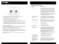
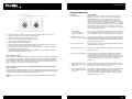
Figure 2: Output Panel Terminals and Indicators
14. POWER AND PROTECT INDICATOR (PWR/PRT)
Green light indicates that the amplifier is "ON." Red light indicates either a high current,
short circuit or DC offset is detected at the speaker outputs. The amplifier will revert to normal
operation once the problem is rectified. The red indicator also lights up at a high operating
temperature. Under this condition, the amplifier will automatically shut down. As soon as the
temperature falls to a safe level, the amplifier will automatically resume operation.
15. POWER INPUT TERMINAL (B+)
To be connected to the positive terminal of the vehicle’s battery or other constant +12 V
source.
16. GROUND INPUT TERMINAL (GND)
To be wired to the vehicle’s chassis for ground.
17. REMOTE TURN-ON INPUT TERMINAL (REM)
To be connected to the remote control wire or power antenna lead of the source unit for
remote ON/OFF.
18. FUSE RECEPTACLE
9. REAR CHANNEL HIGH-PASS/LOW-PASS FREQUENCY SELECTOR KNOB (FREQ)
Select high/low-pass crossover frequency between 30 Hz to 300Hz.
19. FRONT CHANNEL LEFT/RIGHT SPEAKER OUTPUT TERMINAL
For connection to the front speaker system.
10. REAR CHANNEL BASS BOOST CONTROL (BOOST)
Select a boost level between 0dB and +18dB to enhance bass performance of your sound
system.
20. REAR CHANNEL LEFT/RIGHT SPEAKER OUTPUT TERMINAL
For connection to the rear speaker system.
5
COUSTIC.COM
INSTALLATION
By purchasing the 4-channel 321QE/481QE amplifier, you are already one step closer to experiencing the purest and most natural sound quality in the automobile environment. To take full advantage of the potential of this amplifier, before installation, we strongly recommend that you acquaint
yourself with all its available features and then spend some time in designing a system most suitable for you. Take into consideration the components you have now and those that you plan on
adding or upgrading in the future.
The 321QE/481QE power amplifiers are designed for use with a 12-Volt negative ground system.
Installing this amplifier in a vehicle with a POSITIVE ground system will result in severe damage to
the amplifier, other audio components and/or the vehicle’s electrical components. If your vehicle
happens to run on a positive ground system, please consult your Coustic dealer.
Caution: Please follow all the installation recommendations and instructions in this manual. Installing
and/or using the amplifier in methods other than those outlined herein may reduce the performance capability of the amplifier. Any such installation or usage renders the product
warranty void.
Warning: The battery ground should remain DISCONNECTED at all stages of installation.
LOCATION
Ventilation: The primary deciding factor of amplifier location is heat dissipation. Despite its highly
efficeint heat dissipation design, the amplifier can be crippled by inadequate ventilation. Prolonged
operation at high volumes, combined with inadequate ventilation, may cause the amplifier to overheat and trigger the automatic shut down circuit until the temperature returns to a safe level. To
ensure adequate ventilation, the ideal location for the amplifier is a spot away from any heat
source, with at least 2 inches of clearance above and around the unit.
Vibration: Constant vibration could eventually cause the amplifier to come off from mount, resulting
in stress on wire connections, which, in turn, results in "open" or "short" circuit. For this reason, a
location with minimum vibration and a flat surface for secure and firm mounting should be chosen
for the amplifier.
Moisture: The amplifier should never be exposed to moisture and water.
Taking all the above into consideration, the best mounting position for the amplifier would be the
floor of the trunk or behind the rear seat back.
Once the location of all the components has been determined, plan the best routes for all the necessary wiring, making sure that the wires are easily accessible without dismounting the various
components.
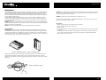
MOUNTING
1. Place the amplifier at the desired location and use it as a template to determine the exact position of the mounting holes.
2. Mark the mounting holes with a felt pen.
3. Put the amplifier aside.
4. If the mounting surface is carpeted, cut out small circles of the carpet and padding around the
four mounting holes to expose the metal underneath.
5. Use a center punch to ensure drilling the exact position for the screws. DO NOT BEGIN
DRILLING UNTIL YOU HAVE PUT THE AMPLIFIER ASIDE. USING THE AMPLIFIER AS A
DRILLING GUIDE MAY CAUSE IRREPARABLE DAMAGE TO THE AMPLIFIER.
6. Mount the amplifier with the screws provided.
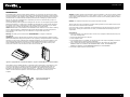
Figure 3: Upright Mount on Horizontal Surface Figure 4: Parallel Mount on Vertical Surface
The amplifier may be mounted upright on a horizontal surface (see Figure 3) or parallel to a vertical surface (see Figure 4). However, the amplifier should never be mounted upside down (see
Figure 5) for the simple reason that the hot air generated by the amplifier would have to go
through the unit internally on its natural upward path (i.e., "feedback" into the unit) and would
result in increased internal temperature. This would speed up the thermal shut down of the
amplifier.
Figure 5: Inverted Mount
(Not Recommended)
7
COUSTIC.COM
+
R
CD-328
+
+
R
CD Changer Control
CD-328
+
Coustic
Coaxial
Front
321QE/481QE
(crossover set to OFF position)
Coustic
Coaxial
Front
Coustic
Coaxial
Rear
321QE/481QE
(crossover: front set to 100Hz Hi-Pass
rear set to 100Hz Hi-Pass)
Coustic
Coaxial
R
Rear
+
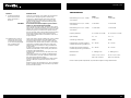
Figure 6. Typical Full Range System
R
+
+
R
CD-328
+
401SE
(crossover set to 100Hz Lo-Pass
CD Changer Control
Coustic
Subwoofers
Coustic
Coaxial
Front
R
+
321QE/481QE
(crossover: front set @ 100Hz Hi-Pass, rear set @ 100Hz Lo-Pass)
Figure 8. Typical High/Low Pass System with two (2) amplifiers
Coustic
Subwoofer
R
+
BI-AMPLIFICATION
Rear
A bi-amplified system normally consists of an active crossover and two amplifiers. The active
crossover divides the audio frequency spectrum into two ranges: frequencies below the crossover
point are directed to the amplifier driving the subwoofer(s), while all frequencies above the
crossover point are directed to the amplifier driving the mid-range/tweeters.
Figure 7. Typical High/Low Pass System with one amplifier
9
COUSTIC.COM
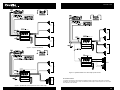
INSTALLATION
FOR BRIDGED (MONO) MODE
continued
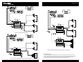
INPUT CONNECTIONS
Connect the front and rear RCA input jacks of the Amplifier to the outputs of the Source Unit (i.e.,
radio, cassette player or CD player). If line level output is not available, connect the speaker outputs of the source unit to the Speaker Level input of the amplifier.
GROUND (black)
LEFT REAR(yel/blk) LEFT REAR(yellow) +
LEFT FRONT(wht/blk) -
FRONT
INPUT
OUTPUT
LEFT FRONT(white) +
FRONT
Note: For bridged mono mode, we recommend a total load of 4 or 8 ohms.
1. Connect the front left positive ("+") speaker output of the amplifier to the positive input terminal
of the speaker.
2. Connect the front right negative ("–") speaker output of the amplifier to the negative input terminal of the speaker.
3. Repeat the same for the rear channel.
4. Make sure that ALL RCAs (front and rear left/right) are plugged in, other wise bass response
and output will suffer.
REAR
MODE
HPF OFF LPF
L
SPKR
SENS
LEVEL
+
R
MIN
L
BRIDGE
+
R
-
MAX
FRONT
REAR
RIGHT FRONT(blu/blk) RIGHT FRONT(blue) +
+
RIGHT REAR(grn/blk) -
L
+
BRIDGE
R
-
RIGHT REAR(green) +
Figure 9: High/Low Impedance Inputs
Note: Connect the black ground wire to the source unit ground only if alternator noise is
present.
Connect the Amplifier to the Speakers. Use thicker speaker wires (e.g. 8 - 10 gauge desirable) for
these connections.
Figure 11: Bridged Single Woofer Connection
CAUTION: ANY DEVIATION FROM THE ABOVE SPEAKER CONNECTION MAY CAUSE
SERIOUS DAMAGE TO THE AMPLIFIER AND/OR SPEAKERS. PLEASE DOUBLE CHECK THE
CONNECTION BEFORE TURNING THE SYSTEM ON.
FOR STEREO MODE
Note: We recommend a total speaker load of 2, 4 or 8 ohms per channel
1. Connect the front left negative ("–") speaker output of the amplifier to the negative terminal of
the left speaker.
2. Connect the front left positive ("+") speaker output of the amplifier to the positive terminal of
the left speaker.
3. Connect the front right ("–") speaker output of the amplifier to the negative terminal of the right
speaker.
4. Connect the front right ("+") speaker output of the amplifier to the positive terminal of the right
speaker.
5. Repeat the same for the rear channel speaker connections.
+
L
BRIDGE
+
R
FRONT
REAR
+
L
+
BRIDGE
R
-
Figure 10: Stereo Connection
11
COUSTIC.COM
CONNECTING AMPLIFIER POWER WIRE TO THE BATTERY
Note: Power cables are as important as battery capacity. Use only high quality power cables of
gauge size AWG 8 (AWG 4 for the 481QE) or larger for installation. YOU CAN NEVER HAVE
TOO BIG OF A POWER/GROUND WIRE!
Run the power cable through the interior of the vehicle connecting one end to the amplifiers B+
terminal and connecting the other end to the positive post on the battery. Be sure not to run the
power cable together with the audio cables as it would invariably cause radiated engine noise in
your audio system. If possible, run audio cables on one side of your car and power cables on the
other. Never route these wires underneath the vehicle body.
It is also advisable to install a circuit breaker/fuse 18” from the battery. This would effectively
lower the risk of the power cable catching fire should a short circuit occur in the audio system. A
circuit breaker or fuse with 50% of the main batteries’ amp hour rating is recommended. Going
larger in circuit breaker or fuse value means that you have NO protection. DO NOT over fuse!
Fuses on the amplifier DO NOT protect the amplifier, they protect the car.
ADJUSTMENTS
CROSSOVER SELECTION
The amplifier has built-in high-pass/low-pass filters for both front and rear channels that can be
defeated by sliding the switch to the OFF position.
1. When the high-pass is selected, the amplifier will be devoted to mid/tweeters.
2. When the low-pass is selected, the amplifier will be used to drive woofers/subwoofers.With
this setting, the optional R S can directly control the amplifier playback level.
3. When the filter is switched off, the amplifier is used as a full range amplifier.
CROSSOVER FREQUENCY SELECTION
Both the high-pass and the low-pass section offer continuously adjustable crossover frequencies
between 30 Hz and 300 Hz. Adjust the setting according to your speaker component specification or to your particular preference.
CONNECTING AMPLIFIER GROUND WIRE TO THE VEHICLE CHASSIS
Find a good ground spot on the vehicles chassis and remove the paint to reveal bare metal at the
contact point. Attach the ground wire to that contact point and connect the other end of the
ground wire to the GND terminal of the amplifier.
TERMINALS, LUGS AND CONNECTORS
Front:High-Pass
Frequency adjustment
FRONT
REAR
MODE
RECONNECT THE BATTERY GROUND TO THE VEHICLE CHASSIS
Double check all the previous installation steps, in particular, the wiring and component connection. If everything is in order, complete the installation by reconnecting the battery ground to the
vehicle chassis.
OPTIONAL REMOTE SUBWOOFER GAIN CONTROL (R S)
If the optional remote subwoofer level control (model R S) is used, connect the plug of the R S to
the port on the end panel of the amplifier.
FRONT
INPUTS
MODE
60
REAR
FREQ
MIN
MAX
60
FREQ
HPF OFF LPF
30
SENS
MODE
180
HPF OFF LPF
0
BOOST
300
+18
30
SENS
MIN
MAX
0
BOOST
180
300
REMOTE
+18
60
REAR
FREQ
180
HPF OFF LPF
CONNECT THE AMPLIFIER REMOTE CONTROL
Connect the remote REM terminal of the amplifier to the remote output terminal of the source unit
to establish amplifier remote on/off through the power on/off of the source unit. If the source unit
does not provide a remote output, connect to its power antenna lead or other switched 12-volt
source, e.g. ignition switch.
Rear:Low-Pass Selected
Front:High-Pass Selected
UTS
High current terminals, lugs and/or connectors are also required to ensure a safe and sure electrical connection and conduction.
Rear:Low-Pass
Frequency adjustment
60
FREQ
180
HPF OFF LPF
30
SENS
MODE
300
BOOST
30
SENS
300
BOOST
REMOTE
SUB LEVEL
Figure 13: Crossover Frequency AdjustmentI
INPUT SENSITIVITY ADJUSTMENT
The Input Sensitivity Control is located on the Input Panel. The objective of input sensitivity adjustment is to match the output of the source unit with the input of the amplifier. The output voltage of
individual source units can vary. For example, some source units have an output of 200 mV and
others have 5 Volts or more. To cater to these variations, the QE amplifier has an adjustable input
sensitivity level that ranges from 100 mV to 5 volts.
Adjusting this control requires some experimenting. Basically, you want all the gain at the beginning of the system, NOT at the end (amplifier). Turn your headunit UP and keep your amplifier
gains at the minimum possible setting (counter-clockwise). This will give you the best sound and
signal-to-noise ratio.
Besides better sonic reproduction, proper input sensitivity also helps to prolong the reliability span
of your amplifier by eliminating excessive internal temperature generated by incompatible source
unit output and amplifier input.
Note: Turning the input gain UP does NOT indicate MORE power. Just MORE noise. The input
gain control IS NOT a power control. REMEMBER that the input gain control has nothing to do
with the power output of the amplifier
Figure 12: Remote Subwoofer Gain Control (481QE only)
13
COUSTIC.COM
TROUBLE-SHOOTING SECTION
FRONT
MODE
60
REAR
FREQ
HPF OFF LPF
30
SENS
MIN
5 volts
MAX
0
.1 volt
BOOST
180
MODE
FREQ
PROBABLE CAUSE
1. No power
Check connections to the amplifier's Ground, B+ & Remote
terminals. Check connection at "+" terminal of the battery.
Check the remote turn-on terminal. Ensure it receives power
when the source is turned on (or when the switch is turned
on). Refer to the Installation Section. Check the power line
fuse: if fuse is blown, replace it; if fuse continues to blow,
check the power wire and also the amplifier for a short. If the
short is in the power wire, fix it; if the short is in the amplifier
itself, see your Coustic dealer.
Check the voltage at the amplifier, and the remote ON/OFF
lead. The voltage should measure between 11 V - 15 V. If the
measurement is beyond this range, have the source unit
checked out by an authorized dealer.
2. Power without sound with
red power/protection
indicator on
Turn the amplifier off, and Check all input & output signal
cables and connections. Check the speakers for short with
a VOM (volt meter) or by connecting them to another audio
system. After making sure everything is normal, turn the
amplifier on again.
3. Power without sound with
red power indicator on
The continuous red light of the power indicator signals a
high internal operating temperature, which results in the
amplifier switching off temporarily; when the amplifier cools
down to a safe level, the amp will automatically restart.
4. No sound from one side
Check balance control.
Check speaker connections.
Check signal input connection.
5. Very low sound from
both radio & tape
Check your radio's fader control.
Check the amplifier's Input Sensitivity Level.
6. Frequent automatic
amplifier shut down
This indicates that the amplifier is operating at a continually
undesirable high internal temperature. High operating temperature caused by inadequate ventilation: Refer to the subsection titled LOCATION for better amplifier location.
High operating temperature caused by an excessively low
impedance load, say below 2 ohms stereo or 4 ohms
bridged: Check for bad speakers and/or electronic
crossover, proper passive crossover components; if all else
fails, try rewiring the entire system.
High operating temperature can be caused by an incorrect
input sensitivity level: refer to sub-section titled INPUT SENSITIVITY ADJUSTMENTS for correct setting.
7. "Motorboating": The
amplifier power indicator
going off repeatedly when
the audio system is on
Check the amplifier's connection to the battery.
Check battery voltage. If low, recharge or replace
battery. Check all ground connections.
8. Whining noise when
engine is running with
noise varying with the
accelerator (noise level
varies with source unit
volume control)
Reroute power cable from battery to source unit directly,
bypassing the battery terminal in the fuse box. Check
power connections to be sure they areclean. Check ground
connections to be sure the ground wire is in direct contact
with the bare metal surface of the chassis (with that spot
scraped clean of any paint, rust or grease).
180
HPF OFF LPF
300
+18
60
SYMPTOM
30
SENS
MIN
5 volts
MAX
BOOST
0
300
+18
.1 volt
Figure 14: Input Sensitivity Control
1.
2.
3.
4.
5.
6.
7.
Turn the Input Sensitivity Control all the way down (counter clockwise).
Set the volume control of the source unit to approximately 2⁄3 of its maximum output.
Turn the balance control of the source unit to its center position.
Leave the tone (bass/treble) controls at their usual position.
Play a CD or tape track with wide dynamic range.
Use the Bass Boost Control to enhance the bass performance (if desired).
To locate the optimum input sensitivity setting, ask the person assisting you to turn the Input
Sensitivity Control clockwise until audio distortion starts to develop. Turn the sensitivity control
counter clockwise slightly to minimize the distortion.
8. If you constantly switch between CD/tape and radio, you will need further adjustment since
radio output level differs from that of CD or tape. In this case, you need to locate a balanced
sensitivity setting which is best for both the output level of radio and that of CD or tape.
BASS BOOST CONTROL (BOOST)
Select a boost level between 0dB and +18dB to enhance the bass performance for your sound
system. BASS BOOST is NOT free! Every 3dB of boost costs you twice as much in power. Make
sure to set the final gains...after setting the Bass Boost to work best with your
subwoofer/enclosure combination. More is NOT always better!
SETTING UP 481QE USING REMOTE SUBWOOFER GAIN CONTROL (R S)
If you are using the R S control, make sure to take this into account during set-up procedures of
the subwoofer amplifier. You should set the system up with the R S plugged in, and with the level
knob turned all the way down (counter clockwise).
NOTE: the R S ONLY works in the "rear channel", and ONLY when you’ve selected the LPF (lowpass) crossover configuration.
15
COUSTIC.COM
SYMPTOM
PROBABLE CAUSE
9. Constant level whining
noise (most noise with
source unit volume at
minimum)
Check for a ground loop in the system. Turn the system off
and one by one change the ground connections (by
changing to a different contact point,scraping the level
constant irrespective of metal clean of any paint, rust or
grease). Turn the system on and check for whining noise
after each ground change.
Do not disconnect the Power Amplifier's ground when the
system is on. This could damage the amplifier.
Check for defective signal cables. Disconnect signal cables
at the amplifier and listen carefully for noise. If the noise disappears, run a test pair of signal cables. If there is no undesirable whining noise, reconnect to the amplifier with the
new pair of signal cables. Check battery ground connection
to the vehicle chassis to make sure it is tight and clean.
Check battery negative terminal connection to make sure it
is tight and clean.
CAUTION:
10. Radiated noise: crackling
noise on FM which is not
present when playing tape
or CD (noise varying slightly
with accelerator but is
present at all times)
Check if the noise is actually radiated noise: Tune a portable
radio to the same FM station. Move the portable radio
close to the vehicle engine. If crackling noise comes from
the portable radio, then the noise you have in your vehicle
audio system is radiated noise.Check with a VOM (volt
meter) to make sure the antenna is really grounded to the
vehicle chassis.
To ensure a true ground, break the plastic covering of the
antenna lead and solder a piece of heavy wire (minimum
14-gauge) to the braided shield.
Ground the other end of the wire at the same point as the
radio ground.
Check spark plug wires. They should be suppression-type
wire and less than 2 years old. Otherwise, replace them
with good quality suppression cables.
Make sure engine block is grounded to the vehicle chassis
at a bare metal spot (scraped clean of paint, rust and
grease).
Make sure hood is also grounded. If not, use a ground strap
(which is available from any auto parts store) to ground the
hood to the vehicle chassis.
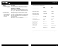
SPECIFICATIONS:
321QE
4 x 40 Watts
481QE
4 x 60 Watts
Rated Power @ 14.4 V (0.1 % THD) :
2 Ohm Stereo
4 x 80 Watts
4 x 120 Watts
Rated Power @ 14.4 V (0.2 % THD) :
4 Ohm Mono
2 x 160 Watts
2 x 240 Watts
Frequency Response :
20 –20,000 Hz ± 0.5dB
20 –20,000 Hz ± 0.5dB
Input Sensitivity:
0.1 – 5 V
0.1 – 5 V
S/N Ratio @ rated power :
100dB
100dB
High-Pass Filter Crossover Frequency :
(Continuously Variable, @18 dB/Oct.)
30 – 300 Hz
30 – 300 Hz
Low-Pass Filter Crossover Frequency :
(Continuously Variable, @ 18 dB/Oct.)
30 – 300 Hz
30 – 300 Hz
Bass Boost Level :
0 – 18dB @ 45 Hz
0 – 18dB @ 45 Hz
Dimensions:
11"W x 23⁄8"H x 133⁄16"L
(280 x 60 x 335mm)
11"W x 23⁄8"H x 143⁄8“L
(280 x 60 x 365mm)
Rated Power @ 14.4 V (0.1 % THD) :
4 Ohm Stereo
Due to continual product improvement, all specifications subject to change without notice.
17
COUSTIC.COM
BIENVENU
...Chez COUSTIC, un univers de puissance et de clarté. Les nouveaux amplis 4 canaux
321/481QE délivrent la puissance la plus parfaite de toute l’industrie du ”12 volts”. En plus d’un
fantastique design, les 321/481QE sont construits avec les technologies les plus récentes et les
plus sophistiqués. Dans ce manuel, vous trouverez une visite guidée de toutes ces excitantes caractéristiques. Pour obtenir le meilleur résultat sonore, veuillez suivre les instructions de montage
aussi bien que possible. Le temps que vous lui consacrerez sera utile pour atteindre un système
haute-fidélité.
CARACTÉRISTIQUES
FILTRE ACTIF INCORPORÉ RÉGLABLE EN CONTINU
Un filtre actif intègre beaucoup d’avantages comparé à un filtre passif : coût réduit, plus simple, plus
souple, générant moins de distorsion et procurant plus de gain. Les 321/481QE intègrent un filtre actif
à 18dB/oct, ajustable en continu, qui peut être configuré en passe-haut, passe bas ou large bande. Les
canaux avant et arrière sont configurables indépendamment.
PROTECTION CONTRE LES SUR-CONSOMMATIONS, LES COURT-CIRCUITS ET LE
COURRANT CONTINU SUR LES ÉTAGES DE PUISSANCE
Pour exploiter au maximum le potentiel de votre ampli, nous vous conseillons de le combiner avec
d’autres produits COUSTIC, comme nos haut-parleurs, nos subwoofers ou encore nos filtres actifs,
qui sont prévus pour parfaitement fonctionner ensemble.
Le très sophistiqué circuit de protection gère les conditions anormales de fonctionnement comme les pics
de tension, les oscillations, l’apparition de courant continu sur les étages de puissance ou encore les
court-circuits. Lorsque l’une de ces mauvaises conditions de fonctionnement dépasse ses limites, le circuit coupe l’ampli pendant un instant et l’indicateur de mise en protection s’allume, permettant d’identifier rapidement le problème. Lorsqu’il est résolu, l’ampli se remet en fonction automatiquement.
Quel que soit le produit dont vous avez besoin pour votre installation ultime, pensez COUSTIC,
avec sa large gamme de composants à même de satisfaire vos demandes les plus exigeantes.
ALIMENTATION PWM À TRANSISTORS MOSFET HIGH SPEED
COUSTIC, un investissement sonore !
Les 321/481QE intègrent une alimentation PWM à transistors MOSFET ultra rapides à très haute
capacité en courant. Ces transistors sont très efficaces, ils ne chauffent que très peu et garantissent un
niveau de fiabilité extrême. De plus, l’alimentation PWM et le très grand nombre de capacité garantissent des basses fermes et profondes.
ÉTAGES DE SORTIE TRIPLE DARLINGTON HIGH CURRENT/HIGH VOLTAGE
Aucune partie de cette publication ne peut être reproduite, stockée ou transmise, sous quelque
forme possible (mécanique ou électronique), sans l’accord écrit de la société COUSTIC ou MITEK
Corporation.
Veuillez aussi noter ci-dessous le numéro de série qui figure sous votre ampli. Conservez ce
manuel comme future référence et comme preuve d’achat.
Les étages de sortie des 321/481QE utilisent des transistors triple Darlington qui sont ultra rapides.
Ces circuits sont longtemps resté l’apanage des réalisations HIFI ésotériques. Ils ont une très forte
capacité en courant, ils assurent une dynamique incroyable. COUSTIC est l’une des rares sociétés qui
utilise ce type de circuit dans le car-audio.
SORTIES LIGNE RCA
Les 321/481QE sont équipés de sorties RCA. Elles permettent de connecter un autre amplificateur avec
une sortie pré-amplifiée. Ce système est de bien meilleure qualité qu’une simple séparation avec des
”Y”. Il est possible de chaîner plusieurs amplis dans le cas d’une extension.
ENTRÉES RCA COMPATIBLES 5 VOLTS
Le niveau d’entrée est réglable de 0,1 volt à 5 volts, ce qui est très flexible. Une telle plage de réglage
permet d’adapter les 321/481QE à toutes les sources du marché.
ENTRÉES LIGNE ET ENTRÉES HAUT-NIVEAU
Les 321/481QE ont des entrées RCA pour une utilisation avec une source équipée de sorties RCA.
Votre ampli est aussi équipé d’entrées haut-niveau lui permettant d’être utilisé dans le cas ou la source
ne serait pas équipée de sorties RCA. Le signal est alors obtenu en connectant les entrées haut-niveau
de l’ampli aux câbles haut-parleur provenant de la source. Si votre source utilise une masse commune
ou une masse flottante sur les sorties, cet ampli est ce qu’il y a de mieux pour votre système. Il est compatible avec les deux standards, et ce, sans adaptateur.
Numéro de série :
Date d’achat :
COMMANDE DE SUBWOOFER DÉPORTÉE EN OPTION (RÉFÉRENCE : R S)
Le 481QE bénéficie d’une commande de subwoofer déportée que vous pouvez vous procurer en
option. Elle permet de régler le niveau du subwoofer de l’avant du véhicule.
ÉGALISEUR DE GRAVE
Il vous permet d’augmenter le rendu de votre système dans le grave. Le réglage s’effectue en continu de
0 à +18dB.
INDICATEUR DE PROTECTION MULTI FONCTIONS
Lorsque l’indicateur s’allume au rouge, cela signifie que l’ampli est en protection thermique et qu’il est
coupé le temps qu’il refroidisse. Dès que la température est revenue à un niveau acceptable, l’ampli se
remet en route automatiquement.
Cet indicateur s’allume aussi lorsque le circuit de protection détecte une sur-consommation, un court-circuit sur les HP ou du courrant continu sur les étages de puissance. Dans ce cas, veuillez éteindre l’ampli pour procéder aux vérifications de câblage et de montage. Si tout est en ordre, vous pouvez rallumer votre ampli.
19
COUSTIC.COM
CONTRÕLES, INDICATEURS ET CONNECTEURS
PANNEAU DES ENTRÉES ET DES CONFIGURATIONS
7
5 12
1
2
FRONT
REAR
MODE
60
11. Contrôle du niveau de sensibilité des canaux arrière
Réglable de 5 volts à 0,1 volt, il doit être réglé en fonction de la source.
9
FRONT
INPUT
OUTPUT
8
REAR
MODE
FREQ
180
HPF OFF LPF
60
FREQ
180
HPF OFF LPF
L
SPKR
30
SENS
LEVEL
BOOST
300
30
SENS
BOOST
300
REMOTE
R
MIN
6
MAX
4
0
+18
3
MIN
MAX
0
11 10
+18
13
12. Entrées haut niveau pour les canaux arrière
Dans le cas ou votre autoradio serait dépourvu de sorties RCA, connecter les câbles
haut-parleurs à ces entrées
13. Connecteur pour la commande de subwoofer déportée R S
Cette commande à distance est en option. Elle permet de régler le niveau du subwoofer à
partir de l’avant du véhicule. Uniquement disponible sur le 480QE.
PANNEAU DES SORTIES
Figure 1: Panneau des entrées et des réglages
1.
16 17 15
Sélecteur du filtre actif avant
Position ”HPF” : Filtre passe haut pour des haut-parleurs avant ou arrière
Position ”OFF” : Filtre déconnecté, l’ampli passe tout le signal sans filtrage
Position ”LPF” : Filtre passe bas, pour filtrer un subwoofer ou un caisson
PWR /PRT
FUSE
GND
REM
19
14 18
+
L
BRIDGE
+
R
-
B+
FRONT
REAR
2.
Contrôle de la fréquence de coupure avant
C’est la fréquence à laquelle le filtre agit. Elle est variable en continu de 30 à 300Hz
3.
Égaliseur de grave avant réglable de 0 à +18dB
Il vous permet d’augmenter le niveau des graves à 45Hz.
4.
Contrôle du niveau de sensibilité des canaux avant
Réglable de 5 volts à 0,1 volt, il doit être réglé en fonction de la source.
5.
Entrées RCA
Doivent être connectées aux sorties RCA de l’autoradio.
6.
Entrées haut niveau pour les canaux avant
Dans le cas ou votre autoradio serait dépourvu de sorties RCA, connecter les câbles
haut-parleurs à ces entrées
7.
8.
9.
Sorties RCA
Ces sorties peuvent être utilisées si vous montez un amplificateur supplémentaire
Sélecteur du filtre actif arrière
Position ”HPF” : Filtre passe haut pour des haut-parleurs avant ou arrière
Position ”OFF” : Filtre déconnecté, l’ampli passe tout le signal sans filtrage
Position ”LPF” : Filtre passe bas, pour filtrer un subwoofer ou un caisson
Contrôle de la fréquence de coupure arrière
C’est la fréquence à laquelle le filtre agit. Elle est variable en continu de 30 à 300Hz
10. Égaliseur de grave arrière réglable de 0 à +18dB
Il vous permet d’augmenter le niveau des graves à 45Hz.
+
L
+
BRIDGE
R
-
20
Figure 2 : Panneau des connecteurs
14. Indicateur de mise en tension et de protection
Led verte : l’amplificateur est allumé
Led rouge : L’amplificateur est en protection. L’ampli repasse automatiquement
au vert lorsque le problème est résolu. En cas de protection thermique, il faut attendre
que l’amplificateur refroidisse pour qu’il redémarre.
15. Connecteur d’alimentation +12V (B+)
Doit être connecté au + 12 volts de la batterie du véhicule.
16. Connecteur de masse (GRD)
Doit être connecté à la masse du véhicule.
17. Connecteur de commande (Remote)
Doit être connecté au câble de commande ou au câble de l’antenne électrique de la
source. Ce bornier commande l’allumage et l’extinction de l’amplificateur.
18. Support de fusible
19. Connecteurs haut-parleurs avant
Doivent être connectés aux haut-parleurs avant.
20. Connecteurs haut-parleurs arrière
Doivent être connectés aux haut-parleurs arrière.
21
COUSTIC.COM
INSTALLATION
En achetant le 321/481QE, vous avez déjà fait un grand pas vers un son pur et naturel. Avant de
passer à l’installation et pour bénéficier de tout le potentiel de votre ampli, nous vous recommandons de lire attentivement ce manuel pour bien connaître toutes les fonctions disponibles. Nous
vous recommandons de prendre le temps d’élaborer un synoptique pour optimiser vos composants
et pour intégrer vos futurs achats.
Le 321/481QE nécessite une alimentation 12 volts avec masse négative. L’installation dans un
véhicule à masse positive entraînera la destruction de l’ampli, du circuit du véhicule concerné ou
encore d’autres composants électriques. Si vous avez le moindre doute à ce sujet, contactez votre
revendeur COUSTIC.
Attention :Veuillez suivre les instructions et les recommandations de ce manuel. Une utilisation dans
d’autres conditions peut réduire les performances de votre ampli. De plus, toute utilisation différente
entraîne la perte de la garantie légale.
Attention : La masse de la batterie doit rester déconnectée durant toute l’installation.
EMPLACEMENT
Refroidissement : Le facteur le plus important dans le choix de l’emplacement est sa capacité de
refroidissement. Malgré ses propres capacités de refroidissement importantes, l’ampli peut souffrir
d’un manque de ventilation. Une utilisation à haut volume, combinée avec un mauvais refroidissement peut conduire à la mise en protection thermique. Il faut donc éviter de placer l’ampli trop près
d’une source de chaleur, avec environ 5cm de vide autour.
Figure 3 : Montage horizontal
Vibrations : Des vibrations trop importantes peuvent détacher l‘ampli qui ne serait plus retenus que
par les fils, ce qui est dangereux. C’est pour cela qu’un montage sur une surface plane, permettant de solides fixations, est recommandé.
Humidité : L’ampli ne doit jamais être exposé à l’humidité ou à l’eau.
En suivant ces recommandations, le meilleur emplacement pour votre ampli reste à plat, dans le
fond du coffre, derrière les sièges arrières.
MONTAGE
1.
2.
3.
4.
Mettre l’ampli en position pour repérer les trous de fixation
Tracer les trous de fixation avec un feutre fin
Enlever l’ampli
S’il y a de la moquette, couper de petits trous pour le passage des vis, pour bien voir le métal
en dessous.
5. Pointer les quatre trous pour obtenir un perçage précis. Ne pas percer tant que l’ampli est en
place. Utiliser l’ampli comme guide de perçage peut entraîner d’irréversibles dégradations.
6. Fixer l’ampli avec les vis fournies
Figure 4 : Montage vertical
L’ampli peut être monté à plat sur une surface horizontale (figure 3) ou à la verticale (figure 4). Il
ne doit jamais être monté à l’envers (figure 5) pour la simple et bonne raison que l’air chaud
généré par l’ampli devrait traverser ses propres composants pour refroidir. Ce qui le ferait chauffer
plus encore.
Figure 5 : Montage à l’envers
23
COUSTIC.COM
+
R
CD-328
+
+
R
CD Changer Control
CD-328
+
Coustic
Coaxial
Front
321QE/481QE
(crossover set to OFF position)
Coustic
Coaxial
Front
Coustic
Coaxial
Rear
321QE/481QE
(crossover: front set to 100Hz Hi-Pass
rear set to 100Hz Hi-Pass)
Coustic
Coaxial
R
Rear
+
Figure 6 : Système traditionnel
R
+
+
R
CD-328
+
401SE
(crossover set to 100Hz Lo-Pass
CD Changer Control
Coustic
Subwoofers
Coustic
Coaxial
Front
R
+
321QE/481QE
(crossover: front set @ 100Hz Hi-Pass, rear set @ 100Hz Lo-Pass)
Figure 8 : Système élaboré avec deux amplis quatre canaux
Coustic
Subwoofer
R
+
BI-AMPLIFICATION
Rear
Un système bi-amplifié est généralement constitué de deux amplis et d’un filtre actifs. Les basses
fréquences sont orientées vers l’ampli du subwoofer pendant que le reste du spectre va vers l’ampli
des médiums et des tweeters.
Figure 7 : Système HP à l’avant plus sub avec un seul ampli
25
COUSTIC.COM
INSTALLATION
MONTAGE PONTÉ (MINIMUM 4Ω)
CONNEXION DU SIGNAL
Connectez l’entrée RCA (input) de l’ampli à la sortie RCA de votre source. Un câble vendu
séparément est nécessaire. Si votre source ne dispose pas de sortie RCA, utilisez les sorties hautparleurs pour alimenter l’amplificateur pas les entrées haut niveau.
Nous recommandons une impédance de 4 ou 8Ω
1. Brancher le connecteur ”+” du subwoofer à la borne ”L +”
2. Brancher le connecteur ”-” du subwoofer à la borne ”R -”
3. Recommencer pour les canaux arrière
4. Vérifier que tous les RCA sont bien connectés pour obtenir une bonne réponse dans le grave
GROUND (black)
LEFT REAR(yel/blk) LEFT REAR(yellow) +
LEFT FRONT(wht/blk) -
FRONT
INPUT
OUTPUT
LEFT FRONT(white) +
FRONT
REAR
MODE
HPF OFF LPF
L
SPKR
SENS
LEVEL
+
R
MIN
L
BRIDGE
+
R
-
MAX
FRONT
REAR
RIGHT FRONT(blu/blk) RIGHT FRONT(blue) +
+
RIGHT REAR(grn/blk) -
L
+
BRIDGE
R
-
RIGHT REAR(green) +
Figure 9 : entrées RCA et entrées haut-niveau
NOTE : lors de l’utilisation des entrées ”haut niveau”, il faut uniquement brancher le câble noir
(situé au centre du connecteur) à la masse du châssis de la source, si un bruit d’alternateur apparaît dans les hp.
Figure 11 : mode ponté sur un seul subwoofer de 4 ohms sur l’avant et l’arrière
ATTETION : Toute autre utilisation ou type de branchement peut entraîner la destruction de l’amplificateur et l’annulation de la garantie. Veuillez vérifier deux fois les branchements avant de mettre sous tension.
Connexion des câbles Haut-parleurs
Il faut connecter l’amplificateur aux haut-parleurs. Veuillez utiliser du câble de bonne qualité d’un
diamètre ne pouvant être inférieur à 1,5mm2.
Montage stéréo (minimum 2Ω, 4Ω et 8Ω possibles)
1. Brancher le connecteur ”-” du hp droit à la borne ”R -”
2. Brancher le connecteur ”+” du hp droit à la borne ”R +”
3. Brancher le connecteur ”-” du hp gauche à la borne ”L -”
4. Brancher le connecteur ”+” du hp gauche à la borne ”L +”
5. Recommencer pour les canaux arrière
+
L
BRIDGE
+
R
FRONT
REAR
+
L
+
BRIDGE
R
-
Figure 10 : mode stéréo.
27
COUSTIC.COM
CÂBLAGE DE L’ALIMENTATION AMPLI/BATTERIE
Les câbles d’alimentation sont aussi importants que la capacité de la batterie elle-même. N’utilisez
que des câbles de bonne qualité d’une section minimum de 20mm2 pour le 321QE et 35mm2
pour le 481QE. Il est impossible d’avoir un câble d’alimentation et de masse trop gros.
Faites passer le câble d’alimentation dans la voiture. Connecter une extrémité à la borne « B+ »
de l’ampli et l’autre extrémité à la borne « + » de la batterie. Pensez à bien séparer les câbles
d’alimentation des câbles RCA, pour éviter le rayonnement cause de parasites. Si possible, faites
passer l’alimentation d’un côté de la voiture et les câbles RCA de l’autre. Ne jamais coller l’alimentation ou les RCA au faisceau de la voiture (encore une source de parasites). Ne jamais faire
passer les câbles par l’extérieur du véhicule.
Il est indispensable d’installer un porte fusible à moins de 50cm de la borne positive de la batterie. Il peut éviter au câble d’alimentation de prendre feu, en cas de court-circuit. La valeur du
fusible dépend de la puissance de la batterie, elle est égale à 50% de la puissance de charge
horaire de celle-ci (pour une batterie de 80 ampères/heure il faut un fusible de 40A). L’utilisation
de fusible de plus forte valeur revient à éliminer la fonction de protection du fusible. Ne jamais
surévaluer le fusible. Les fusibles présents sur l’ampli ne protègent pas l’ampli mais la voiture.
RÉGLAGES
SÉLECTION DU TYPE DE FILTRAGE
Les amplis sont équipés d’un filtre actif passe haut ou passe bas réglable
1. En position ”High Pass” (passe haut), le filtre ne laisse passer que les fréquences hautes
destinées aux haut-parleurs avant ou arrière.
2. En position ”Low Pass” (passe bas), le filtre ne laisse passer que les fréquences basses
destinées aux subwoofers
3. En position ”OFF” (déconnecté), le filtre est déconnecté et il laisse donc passer toutes les
fréquences
SÉLECTION DE LA FRÉQUENCE DE COUPURE
Le filtre actif est réglable en continu de 30Hz à 300Hz, en passse-haut et en passe-bas. Cela permet tous les réglages possibles. Commencez les réglages à 80Hz.
Front:High-Pass
Frequency adjustment
CONNEXION DE L’AMPLIFICATEUR À LA MASSE DU VÉHICULE
Utilisez une bonne masse directement au châssis. Poncer la peinture jusqu’au métal. Relier cette
masse au bornier « GND » de l’amplificateur.
Veuillez utiliser des connecteurs et des borniers de qualité pour assurer toutes les liaisons électriques.
CÂBLE D’ALLUMAGE ET D’EXTINCTION DE L’AMPLI
Connecter la borne « REM » de l’amplificateur au câble « remote » de la source. Si ce câble n’est
pas disponible sur la source, vous pouvez utiliser le câble « antenne ».
RECONNECTER LE CÂBLE DE MASSE DU VÉHICULE
Après double vérification de tous les points cités ci-dessus, et si tout est en ordre, vous pouvez
reconnecter le câble de masse entre le châssis et la borne « - » de la batterie.
COMMANDE DE SUBWOOFER DÉPORTÉE R S (EN OPTION SUR LE 481QE)
Il suffit de connecteur la prise à l’amplificateur pour pouvoir contrôler le niveau du subwoofer.
FRONT
INPUTS
MODE
60
MIN
MAX
MODE
180
60
FREQ
HPF OFF LPF
30
SENS
0
FRONT
UTS
BOOST
300
+18
30
SENS
MIN
MAX
0
BOOST
180
300
MODE
60
REAR
FREQ
180
HPF OFF LPF
60
FREQ
180
HPF OFF LPF
30
SENS
MODE
300
BOOST
30
SENS
300
BOOST
REMOTE
SUB LEVEL
Figure 13 : Réglage de la fréquence de coupure du filtre actif
RÉGLAGE DE LA SENSIBILITÉ
Le potentiomètre de sensibilité d’entrée est situé sur le panneau de configuration de l’ampli. Il permet d’ajuster le niveau d’entrée de l’ampli avec le niveau de sortie de la source. Certaines
sources ont un niveau de sortie de 0,2 volts alors que d’autres dépassent 5 volts. Pour s’adapter,
les 321/481QE sont équipés d’un niveau d’entrée réglable de 0,1 à 5 volts.
Ce réglage est le plus délicat. Il faut une certaine expérience pour parfaitement régler la sensibilité d’un amplificateur. Le meilleur réglage de gain est celui où le niveau est le plus bas. C’est à ce
niveau que le rapport signal sur bruit est le plus grand et donc la qualité sonore la meilleure.
Un bon réglage de gain entraîne une meilleure qualité sonore et une meilleure fiabilité en
réduisant la température interne de l’ampli.
REAR
FREQ
HPF OFF LPF
Rear:Low-Pass Selected
Front:High-Pass Selected
REAR
BORNIERS ET CONNECTEURS
Rear:Low-Pass
Frequency adjustment
REMOTE
+18
NOTE : La puissance de cet ampli n’est pas fonction du réglage de gain. Mettre ce potentiomètre
à fond ne donne pas plus de puissance. Si le niveau est trop haut, vous risquez de détruire les
haut-parleurs (qui dans ce cas ne sont pas garantis). S’il est trop bas, votre installation manquera
de pêche.
Figure 12 : Commande de subwoofer déportée
29
COUSTIC.COM
EN CAS DE DIFFICULTÉ
FRONT
MODE
60
REAR
FREQ
HPF OFF LPF
30
SENS
MIN
5 volts
MAX
0
.1 volt
BOOST
180
MODE
FREQ
Cause probable
Vérifier les connexions à l’ampli alimentation masse et remote.
Vérifier la connexion à la borne + de la batterie. Vérifier que le
remote délivre bien du 12 volts lorsque la source est allumée. .
Vérifier le fusible. S’il est cassé, remplacez le. S’il saute encore,
vérifier le câble sur toute sa longueur et l’ampli contre les court-circuits. Si le court-circuit est sur l’alimentation, réparer la. S’il est dans
l’ampli, retourner chez votre revendeur COUSTIC. Vérifier la tension
aux bornes de l’ampli. Il faut 11 à 15 volts entre la masse et le +,
ainsi qu’entre la masse et le remote. Si ce n’est pas le cas, retournez
chez votre revendeur COUSTIC.
2. Il s’allume sans
son, le led rouge de
protection est allumée
Couper l’ampli, vérifier toutes les connexions et tous les câbles de si
nal et d’alimentation. Vérifier que les HP ne soit pas en court-circuit
avec un voltmètre. Après avoir tout vérifié, vous pouvez rallumer.
180
HPF OFF LPF
300
+18
60
Symptôme
1. Ne s’allume pas
30
SENS
MIN
5 volts
MAX
BOOST
0
300
+18
.1 volt
Figure 14 : Réglage de la sensibilité
1.
2.
3.
4.
5.
6.
7.
Tournez le réglage à fond dans le sens contraire des aiguilles d’une montre (minimum)
Montez le volume de votre autoradio à 2⁄3 du volume maxi
Vérifiez que la balance et le fader soit bien au centre
Vérifiez que les réglages de grave et d’aigu sont à zéro
Prenez un CD ou une cassette qui ”tape fort”
Régler l’égaliseur de grave si nécessaire
Placez -vous dans le véhicule et demandez à quelqu’un de monter le niveau jusqu’à appari
tion de la saturation. Diminuez le niveau d’environ une heure.
8. Si vous passez du CD à la cassette puis à la radio, il vous faudra un peu plus de réglage
pour être parfait. Votre ampli est réglé.
Un bon réglage de gain entraîne une meilleure qualité sonore et une meilleure fiabilité en
réduisant la température interne de l’ampli.
3. L’ampli s’allume, il n’y a
Le led rouge continu indique que l’ampli est en protection thermique,
pas de son, le led est rouge ce qui explique qu’il soit coupé en attendant de refroidir. Lorsque
l’ampli aura retrouvé une température de fonctionnement normale, il
se rallumera automatiquement.
4.Pas d’un son d’un côté
Vérifier la balance, vérifier les câbles des haut-parleurs, vérifier vos
câbles RCA et leurs connexions.
5.Son particulièrement bas.
Vérifier le fader, vérifier le réglage de niveau sur l’ampli, vérifier la
position du filtre actif.
6.Coupures de son fréquentes
L’ampli fonctionne dans de mauvaises conditions de température.
Cela peut provenir d’une mauvaise ventilation, d’un mauvais
emplacement de l’ampli, d’un mauvais réglage de gain (trop haut)
ou d’un montage à l’impédance trop bases (par exemple moins de
2 ohms en stéréo ou moins de 4 ohms ponté). Voir chapitre
concerné.
ÉGALISEUR DE GRAVE
Régler cet égaliseur comme désiré entre 0 et +18dB pour augmenter les basses de votre système
autour de 45Hz. Mais attention, ce réglage n’est pas gratuit pour votre système : tous les 3dB,
votre amplificateur consommera le double de puissance et vos (votre) haut-parleurs encaissent
aussi le double de puissance. Le plus est parfois l’ennemis du bien. De manière générale, il faut
utiliser ce réglage avec parcimonie, alors allez-y doucement.
RÉGLAGE ET UTILISATION DE LA COMMANDE DE SUBWOOFER DÉPORTÉE R S
AVEC LE 481QE
Si vous utilisez la commande déportée R S, tenez-en compte lors de vos réglages. Nous vous conseillons de régler le niveau du subwoofer avec la commande R S réglée à moitié pour permettre
d’augmenter ou de diminuer le niveau du subwoofer par la suite.
7. L’indicateur de mise sous
Vérifier la connexion à la batterie ainsi que le passage du câble.
tension varie lorsque l’ampli Vérifier la tension de la batterie. Si elle est trop faible, recharger là
fonctionne
où remplacer la. Vérifier les câbles de masse.
8. Parasite alternateur variant
avec la vitesse de rotation
du moteur
Faire repasser la câble d’alimentation de l’ampli à un autre endroit.
Faire passer un câble d’alimentation direct de la batterie à la
source. Vérifier toutes les connexions, elles doivent être propres et
pas oxydées.Vérifier la qualité des masses en s’assurant que les
contacts sont bien sur le métal.
Attention : la commande R S ne fonctionne que lorsque le filtre actif est enclenché en position
« LPF ».
31
COUSTIC.COM
Symptôme
9. Bruit de fonctionnement à
bas niveau
ATTETION :
10.Parasites rayonnants
présent en radio mais pas
en CD ou cassette. Le
parasite varie légèrement
en fonction du régime
moteur et il est présent
tout le temps.
Cause probable
Il faut chercher les boucles de masses en changement chaque point
de masse l’un après l’autre.
il ne faut pas débrancher la masse lorsque l’ampli est en fonction
nement. Cela pourrait l’endommager.
Vérifier les câbles RCA qui pourraient être endommagés ou coincés
sous une vis ou un siège. Pour s’en assurer, il suffit d’utiliser un câble
RCA « en volant ». Vérifier la masse du véhicule, elle doit être propre
et non oxydée.
Vérifier que le parasite provient bien de la voiture avec une petite
radio FM que vous approcherez de la voiture sur la même station
que sur votre source. Si vous entendez les mêmes parasites dans votre
radio portable, les parasites sont générés par le composant dont vous
vous êtes rapproché. Vérifier l’antenne radio et sa connexion à la
masse. Vérifier le déparasitage du véhicule. S’il a plus de deux ans,
changer les composants.
Vérifier la mise à la masse du moteur. Vérifier la mise à la masse du
capot du véhicule. S’il n’y en a pas, mettez-en une.
CARACTÉRISTIQUES TECHNIQUES
321QE
481QE
Puissance sous 14,4volts
4 ohms stéréo, 0,1% THD
4 x 40 Watts
4 x 60 W
Puissance sous 14,4volts
2 ohms stéréo, 0,1% THD
4 x 80 Watts
4 x 120 W
Puissance sous 14,4volts
4 ohms ponté, 0,1% THD
2 x 160 Watts
2 x 240 W
Réponse en fréquence
20 - 20000 Hz
(+/- 0,5dB)
20 - 20000 Hz
(+/- 0,5dB)
Sensibilité d’entrée
0,1 à 5 volts
0,1 à 5 volts
S/N ratio @ puissance maxi
100dB
100dB
Filtre actif passe haut
18dB/oct, variable
30 à 300 Hz
30 à 300 Hz
Filtre actif passe bas
18dB/oct, variable
30 à 300 Hz
30 à 300 Hz
Égaliseur de grave
0 à +18dB @ 45 Hz
0 à +18dB @ 45 Hz
Dimensions
280x60x335mm
280x60x365mm
En raison d’améliorations constantes, toutes ces caractéristiques sont susceptibles de changer sans
préavis.
33
COUSTIC.COM
NOTES:
COUSTIC LIMITED WARRANTY
IMPORTANT NOTICE TO CONSUMER:
Coustic offers the following warranty to the ORIGINAL PURCHASER of COUSTIC products, purchased from an authorized Coustic dealer, within the period stated herein:
Coustic warrants the 161SE, 241SE, 401SE, 601SE, 481QE, 321QE amplifiers against defects
in material and workmanship for a period of ONE (1) YEAR from date of original purchase. The
limited warranty is offered as an Over The Counter (OTC) exchange providing that the product
was purchased from an authorized Coustic dealer and is accompanied by valid sales receipt at
the time of exchange. Replacement units will be warranted for the remaining portion of the original warranty period.
IMPORTANT:
THIS WARRANTY DOES NOT COVER INSTALLATION OR DAMAGE RESULTING FROM ACCIDENT, MISUSE, ABUSE, IMPROPER WIRING, INCORRECT VOLTAGE, OPERATING UNIT
AGAINST INSTRUCTIONS IN OWNER’S MANUAL OR ANY PRODUCT WHICH HAS BEEN
OPENED, TAMPERED WITH OR SERIAL NUMBERS REMOVED.
This warranty does not cover labor costs for removal and/or installation of the unit for repair.
Under no circumstances shall Coustic be liable for any special, incidental or consequential damages or for any other expenses incurred by reason of use or implied including any implied warranty of merchantability or fitness for particular use or otherwise.
This warranty gives the CONSUMER specific legal rights and he may also have other rights which
vary from state to state. Some states do not follow the exclusion or limitation of incidental or consequential damages, hence the above exclusions and limitations may not apply.
For additional information, call us at 1-602-438-2020, or visit our website at coustic.com.
35
7676 SOUTH 46 STREET, SUITE 2020, PHOENIX, AZ 85042
TOLL FREE 877 COUSTIC TELEPHONE 602 438 2020 FACSIMILE 602 438 7313
coustic.com
© 2 0 0 2 . C O U S T I C I S A R E G I S T E R E D T R A D E M A R K O F M I T E K C O R P O R AT I O N . A L L R I G H T S R E S E R V E D .
COU000769 RevB 1/02
NDM195