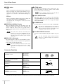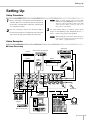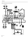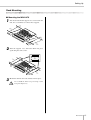
1
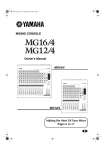
MIXING
MIXING CONSOLE
CONSOLE
Owner’s Manual
Making the Most Of Your Mixer
Pages 6 to 16
EN
PRECAUTIONS
PLEASE READ CAREFULLY BEFORE PROCEEDING
* Please keep this manual in a safe place for future reference.
WARNING
Always follow the basic precautions listed below to avoid the possibility of serious injury or even death from electrical
shock, short-circuiting, damages, fire or other hazards. These precautions include, but are not limited to, the following:
Power supply/Power cord
Water warning
• Only use the voltage specified as correct for the device. The required voltage is
printed on the name plate of the device.
• Do not expose the device to rain, use it near water or in damp or wet conditions,
or place containers on it containing liquids which might spill into any openings.
• Use only the specified AC power adaptor (PA-20 or an equivalent recommended
by Yamaha).
• Never insert or remove an electric plug with wet hands.
• Do not place the power cord near heat sources such as heaters or radiators, and
do not excessively bend or otherwise damage the cord, place heavy objects on
it, or place it in a position where anyone could walk on, trip over, or roll anything
over it.
Do not open
• Do not open the device or attempt to disassemble the internal parts or modify
them in any way. The device contains no user-serviceable parts. If it should
appear to be malfunctioning, discontinue use immediately and have it inspected
by qualified Yamaha service personnel.
If you notice any abnormality
• If the power cord or plug becomes frayed or damaged, or if there is a sudden
loss of sound during use of the device, or if any unusual smells or smoke
should appear to be caused by it, immediately turn off the power switch,
disconnect the electric plug from the outlet, and have the device inspected by
qualified Yamaha service personnel.
• If this device or the AC power adaptor should be dropped or damaged,
immediately turn off the power switch, disconnect the electric plug from the
outlet, and have the device inspected by qualified Yamaha service personnel.
CAUTION
Always follow the basic precautions listed below to avoid the possibility of physical injury to you or others, or damage
to the device or other property. These precautions include, but are not limited to, the following:
Power supply/Power cord
• Remove the electric plug from the outlet when the device is not to be used for
extended periods of time, or during electrical storms.
• When removing the electric plug from the device or an outlet, always hold the
plug itself and not the cord. Pulling by the cord can damage it.
• To avoid generating unwanted noise, make sure there is 50 cm or more
between the AC power adaptor and the device.
• Do not cover or wrap the AC power adaptor with a cloth or blanket.
Location
• Before moving the device, remove all connected cables.
• Avoid setting all equalizer controls and faders to their maximum. Depending on
the condition of the connected devices, doing so may cause feedback and may
damage the speakers.
• Do not expose the device to excessive dust or vibrations, or extreme cold or heat
(such as in direct sunlight, near a heater, or in a car during the day) to prevent
the possibility of panel disfiguration or damage to the internal components.
• Do not place the device in an unstable position where it might accidentally fall
over.
• Do not use the device in the vicinity of a TV, radio, stereo equipment, mobile
phone, or other electric devices. Otherwise, the device, TV, or radio may
generate noise.
2
MG12/4FX
Connections
• Before connecting the device to other devices, turn off the power for all devices.
Before turning the power on or off for all devices, set all volume levels to
minimum.
Handling caution
• Do not insert your fingers or hand in any gaps or openings on the device.
• Avoid inserting or dropping foreign objects (paper, plastic, metal, etc.) into any
gaps or openings on the device. If this happens, turn off the power immediately
and unplug the power cord from the AC outlet. Then have the device inspected
by qualified Yamaha service personnel.
• Do not use the device or headphones for a long period of time at a high or
uncomfortable volume level, since this can cause permanent hearing loss. If you
experience any hearing loss or ringing in the ears, consult a physician.
• Do not rest your weight on the device or place heavy objects on it, and avoid use
excessive force on the buttons, switches or connectors.
XLR-type connectors are wired as follows (IEC60268 standard): pin 1: ground, pin 2: hot (+), and pin 3: cold (–).
Insert TRS phone jacks are wired as follows: sleeve: ground, tip: send, and ring: return.
Yamaha cannot be held responsible for damage caused by improper use or modifications to the device.
Always turn the power off when the device is not in use.
Even when the power switch is in the “STANDBY” position, electricity is still flowing to the device at the minimum level. When you are not using the device for a long time,
make sure you unplug the power cord from the wall AC outlet.
The performance of components with moving contacts, such as switches, volume controls, and connectors, deteriorates over time. Consult qualifi ed Yamaha service
personnel about replacing defective components.
Copying of the commercially available music data and/or digital audio files is strictly prohibited except for your personal use.
Illustration examples shown herein are for explanatory purposes only, and may not match actual appearance during operation.
The company names and product names in this Owner’s Manual are the trademarks or registered trademarks of their respective companies.
IMPORTANT NOTICE FOR THE UNITED KINGDOM
Connecting the Plug and Cord
IMPORTANT. The wires in this mains lead are coloured in accordance with the following code:
BLUE
: NEUTRAL
BROWN : LIVE
As the colours of the wires in the mains lead of this apparatus may not correspond with the coloured makings identifying the terminals in your
plug proceed as follows:
The wire which is coloured BLUE must be connected to the terminal which is marked with the letter N or coloured BLACK.
The wire which is coloured BROWN must be connected to the terminal which is marked with the letter L or coloured RED.
Making sure that neither core is connected to the earth terminal of the three pin plug.
•This applies only to products distributed by Yamaha-Kemble Music (U.K.) Ltd. (2 wires)
FCC INFORMATION (U.S.A.)
1. IMPORTANT NOTICE: DO NOT MODIFY THIS UNIT!
This product, when installed as indicated in the instructions
contained in this manual, meets FCC requirements. Modifications not expressly approved by Yamaha may void your authority, granted by the FCC, to use the product.
2. IMPORTANT: When connecting this product to accessories
and/or another product use only high quality shielded cables.
Cable/s supplied with this product MUST be used. Follow all
installation instructions. Failure to follow instructions could void
your FCC authorization to use this product in the USA.
3. NOTE: This product has been tested and found to comply with
the requirements listed in FCC Regulations, Part 15 for Class
“B” digital devices. Compliance with these requirements provides a reasonable level of assurance that your use of this
product in a residential environment will not result in harmful
interference with other electronic devices. This equipment generates/uses radio frequencies and, if not installed and used
according to the instructions found in the users manual, may
cause interference harmful to the operation of other electronic
devices. Compliance with FCC regulations does not guarantee
that interference will not occur in all installations. If this product
is found to be the source of interference, which can be determined by turning the unit “OFF” and “ON”, please try to eliminate the problem by using one of the following measures:
Relocate either this product or the device that is being affected
by the interference.
Utilize power outlets that are on different branch (circuit
breaker or fuse) circuits or install AC line filter/s.
In the case of radio or TV interference, relocate/reorient the
antenna. If the antenna lead-in is 300 ohm ribbon lead, change
the lead-in to co-axial type cable.
If these corrective measures do not produce satisfactory
results, please contact the local retailer authorized to distribute
this type of product. If you can not locate the appropriate
retailer, please contact Yamaha Corporation of America, Electronic Service Division, 6600 Orangethorpe Ave, Buena Park,
CA90620
The above statements apply ONLY to those products distributed by Yamaha Corporation of America or its subsidiaries.
* This applies only to products distributed by YAMAHA CORPORATION OF AMERICA. (class B)
MG12/4FX
3
Introduction
Introduction
Thank you for your purchase of the YAMAHA MG12/4FX mixing console. The MG12/4FX features input channels suitable for
a wide range of usage environments, and includes high-quality built-in digital effects that can provide some very serious sound.
The mixer combines ease of operation with support for multiple usage environments.
Please read through this manual carefully before beginning use, so that you will be able to take full advantage of this mixer’s
superlative features and enjoy trouble-free operation for years to come.
Contents
Introduction
Features
4
Input Channels................................ page 21
Contents .............................................................. 4
Features ............................................................... 4
Before Turning on the Mixer ................................. 5
Turning the Power On .......................................... 5
With up to six mic/line inputs or up to four stereo
inputs, the MG12/4FX can simultaneously connect to
a wide range of devices: microphones, line-level
devices, stereo synthesizers, and more. For example, you can connect four microphones and four stereo devices, or six microphones and two stereo
devices.
Making the Most Of Your Mixer
6
1. A Place For Everything and
Everything In Its Place.................................... 6
2. Where Your Signal Goes Once
It’s Inside the Box ........................................... 9
3. The First Steps in Achieving
Great Sound ................................................. 10
4. External Effects, Monitor Mixes,
and Groups ................................................... 12
5. Making Better Mixes..................................... 15
Front & Rear Panels
17
Channel Control Section .................................... 17
Master Control Section ...................................... 19
Rear Input/Output Section ................................. 21
Setting Up
23
Setup Procedure ................................................ 23
Setup Examples ................................................. 23
Rack Mounting ................................................... 25
Appendix
26
Specifications ..................................................... 26
Dimensional Diagrams ....................................... 28
Block Diagram and Level Diagram .................... 29
4
MG12/4FX
Phantom Power (+48 V) .................. page 19
A single switch turns phantom power on or off for all
six mic inputs. Phantom power enables easy connection to condenser microphones that require external power.
High-quality digital effects............. page 20
With digital effects built in, the MG12/4FX can deliver
a wide range of sound variations all by itself. The unit
also includes an EFFECT SEND jack that can be
used to connect an external effector.
AUX Sends and Stereo
AUX Return................................ page 17, 19
You can use the AUX SEND jack to feed the
post-fader signal to an external signal processor, and
then return the processed stereo signal through the
RETURN jack. Alternatively, you can use the PRE
switch on each channel to send that channel’s
pre-fader signal out through the AUX SEND jack for
monitoring.
Rack Mounting ................................ page 25
The mixer provides two metal rack-mount supports,
and integrates easily into a wide variety of setups.
Introduction
Before Turning on the Mixer
Turning the Power On
1
Press the mixer’s power switch to the ON position. When
you are ready to turn the power off, press the power switch to
the STANDBY position.
Be sure that the mixer’s power switch is in the
STANDBY position.
Use only the PA-20 adaptor included with this
mixer. Use of a different adaptor may result in
equipment damage, overheating, or fire.
2
Note that trace current continues to flow while the
switch is in the STANDBY position. If you do not
plan to use the mixer again for a long while, please
be sure to unplug the adaptor from the wall outlet.
Connect the power adaptor to the AC ADAPTOR IN
connector (1) on the rear of the mixer, and then turn
the fastening ring clockwise (2) to secure the connection.
2
1
3
Plug the power adaptor into a standard household
power outlet.
•
Be sure to unplug the adaptor from the outlet
when not using the mixer, or when there are lightning storms in the area.
•
To avoid generating unwanted noise, make sure
there is 50 cm or more between the power adaptor
and the mixer.
MG12/4FX
5
Making the Most Of Your Mixer
Making the Most Of Your Mixer
■ An Introduction
You’ve got yourself a mixer and now you’re ready to use it.
Just plug everything in, twiddle the controls, and away you go … right?
Well, if you’ve done this before you won’t have any problems, but if this is
the first time you’ve ever used a mixer you might want to read through this little tutorial and pick up a few basics that will help you get better performance
and make better mixes.
1. A Place For Everything and Everything In Its Place
1-1. A Plethora Of Connectors—What Goes Where?
Questions you’re likely to encounter when setting up a system for the first time might include “Why all these different types of
connectors on the back of my mixer?” and “What’s the difference?”.
Let’s start by taking a look at the most common connector types.
■ The Venerable RCA Pin Jack
White
Red
This is the “consumer connector,” and the one that has been most commonly used on
home audio gear for many years. Also known as “phono” jacks (short for “phonogram”),
but the term isn’t used much these days—besides, it’s too easily confusable with
“phone” jacks, below. RCA pin jacks are always unbalanced, and generally carry a
line-level signal at –10 dB, nominal. You’re most likely to use this type of connector
when connecting a CD player or other home audio type source to your mixer, or when
connecting the output of your mixer to a cassette recorder or similar gear.
■ The Versatile Phone Jack
Stereo/TRS phone plug
Mono phone plug
6
MG12/4FX
The name “phone jack” arose simply because this configuration was first used in
telephone switchboards. Phone jacks can be tricky because you can’t always tell what
type of signal they’re designed to handle just by looking at them. It could be unbalanced
mono, unbalanced stereo, balanced mono, or an insert patch point. The connector’s label
will usually tell you what type of signal it handles, as will the owner’s manual (you do
keep your manuals in a safe place, don’t you?). A phone jack that is set up to handle
balanced signals is also often referred to as a “TRS” phone jack. “TRS” stands for
Tip-Ring-Sleeve, which describes the configuration of the phone plug used.
Making the Most Of Your Mixer
■ The Sturdy XLR
Male
This type of connector is generally referred to as “XLR-type,” and almost always carries
a balanced signal. If the corresponding circuitry is designed properly, however,
XLR-type connectors will also handle unbalanced signals with no problem. Microphone
cables usually have this type of connector, as do the inputs and outputs of most
professional audio gear.
Female
1-2. Balanced, Unbalanced—What’s the Difference?
In a word: “noise.” The whole point of balanced lines is noise rejection, and it’s something they’re very good at. Any length of
wire will act as an antenna to pick up the random electromagnetic radiation we’re constantly surrounded by: radio and TV
signals as well as spurious electromagnetic noise generated by power lines, motors, electric appliances, computer monitors, and
a variety of other sources. The longer the wire, the more noise it is likely to pick up. That’s why balanced lines are the best
choice for long cable runs. If your “studio” is basically confined to your desktop and all connections are no more than a meter or
two in length, then unbalanced lines are fine—unless you’re surrounded by extremely high levels of electromagnetic noise.
Another place balanced lines are almost always used is in microphone cables. The reason for this is that the output signal from
most microphones is very small, so even a tiny amount of noise will be relatively large, and will be amplified to an alarming
degree in the mixer’s high-gain head amplifier.
To summarize:
Microphones:
Short line-level runs:
Long line-level runs:
Use balanced lines.
Unbalanced lines are fine if you’re in a relatively noise-free environment.
The ambient electromagnetic noise level will be the ultimate deciding factor, but balanced is
best.
■ How Do Balanced Lines Reject Noise?
** Skip this section if technical details make you queasy. **
Balanced lines work on the principle of “phase cancellation”: if you add two identical signals out of phase (i.e. one signal is
inverted so its peaks coincide with the troughs in the other signal), the result is … nothing. A flat line. The signals cancel each
other out.
Normal-phase signal.
No signal.
(Phase cancellation)
Reverse-phase signal.
MG12/4FX
7
Making the Most Of Your Mixer
A balanced cable has three conductors:
1)
2)
3)
A ground conductor which carries no signal, just the “ground” or “0” reference against which the signal in the other
conductors fluctuates.
A “hot” or “+” conductor which carries the normal-phase audio signal.
A “cold” or “–” conductor which carries the reverse-phase audio signal.
While the desired audio signals in the hot and cold conductors are out of phase, any noise induced in the line will be exactly the
same in both conductors, and thus in phase. The trick is that the phase of one signal is reversed at the receiving end of the line so
that the desired audio signals become in-phase, and the induced noise suddenly finds itself out of phase. The out-of-phase noise
signal is effectively canceled while the audio signal is left intact. Clever, eh?
Normal-phase signal
+ normal-phase noise.
Desired signal
with no noise.
Normal-phase signal
+ reverse-phase noise.
1-3. Signal Levels—Decibel Do’s and Don’ts
From the moment you start dealing with things audio, you’ll have to deal with the term “decibel” and its abbreviation, “dB”.
Things can get confusing because decibels are a very versatile unit of measure used to describe acoustic sound pressure levels as
well as electronic signal levels. To make matters worse there are a number of variations: dBu, dBV, dBm. Fortunately, you don’t
need to be an expert to make things work. Here are a few basics you should keep in mind:
● “Consumer” gear (such as home audio equipment) usually has line inputs and outputs with a nominal (average) level of
–10 dB.
● Professional audio gear usually has line inputs and outputs with a nominal level of +4 dB.
● You should always feed –10 dB inputs with a –10 dB signal. If you feed a +4 dB signal into a –10 dB input you are likely to
overload the input.
● You should always feed +4 dB inputs with a +4 dB signal. A –10 dB signal is too small for a +4 dB input, and will result in
less-than-optimum performance.
● Many professional and semi-professional devices have level switches on the inputs and/or outputs that let you select –10 or
+4 dB. Be sure to set these switches to match the level of the connected equipment.
● Inputs that feature a “Gain” control—such as the mono-channel inputs on your Yamaha mixer—will accept a very wide range
of input levels because the control can be used to match the input’s sensitivity to the signal. More on this later.
8
MG12/4FX
Making the Most Of Your Mixer
2. Where Your Signal Goes Once It’s Inside the Box
At first glance the block diagram of even a modest mixer can look like a space-station schematic. In reality, block diagrams are
a great aid in understanding how the signal flows in any mixer. Here’s a greatly simplified block diagram of a generic mixer to
help you become familiar with the way these things work.
2-1. Greatly Simplified Mixer Block Diagram
Input Channel
Master Section
Signals from the mixer’s
other input channels
(if they are assigned to this
master output or “bus”).
1
2
3
4
■ Input Channel
■ Master Section
1 Head Amp
4 Summing Amplifier
The very first stage in any mixer, and usually the only
stage with significant “gain” or “amplification.” The head
amp has a “gain” control that adjusts the mixer’s input
sensitivity to match the level of the source. Small signals
(e.g. mics) are amplified, and large signals are attenuated.
2 Equalizer
Could be simple bass and treble controls or a full-blown
4-band parametric EQ. When boost is applied the EQ
stage also has gain. You can actually overload the input
channel by applying too much EQ boost. It’s usually
better to cut than boost.
5
This is where the actual “mixing” takes place. Signals
from all of the mixer’s input channels are “summed”
(mixed) together here.
5 Master Fader & Level Meter
A stereo, mono, or bus master fader and the mixer’s main
output level meter. There could be several master faders
depending on the design of the mixer—i.e. the number of
buses or outputs it provides.
3 Channel Peak LED & Fader
The channel peak LED is your most valuable tool for
setting the input “gain” control for optimum
performance. Note that it is located after the head amp
and EQ stage.
MG12/4FX
9
Making the Most Of Your Mixer
3. The First Steps in Achieving Great Sound
Before you even consider EQ and effects, or even the overall mix, it is important to make sure that levels are properly set for
each individual source. This can’t be stressed enough—initial level setup is vitally important for achieving optimum performance from your mixer! Here’s why … and how.
3-1. The Head Amplifier “Gain” Control Is the Key!
Let’s review our simplified mixer block diagram:
Each and every “stage” in the mixer’s signal path will add a certain amount of noise to the signal: the head amp, the EQ stage,
the summing amplifier, and the other buffer and gain stages that exist in the actual mixer circuit (this applies to analog mixers in
particular). The thing to keep in mind is that the amount of noise added by each stage is usually not dependent to any significant
degree on the level of the audio signal passing through the circuit. This means that the bigger the desired signal, the smaller the
added noise will be in relation to it. In tech-speak this gives us a better “signal-to-noise ratio”—often abbreviated as “S/N ratio.”
All of this leads to the following basic rule:
To achieve the best overall system S/N ratio, amplify the input to the desired average level as
early as possible in the signal path.
In our mixer, that means the head amplifier. If you don’t get the signal up to the desired level at the head amplifier stage, you will
need to apply more gain at later stages, which will only amplify the noise contributed by the preceding stages. Just remember
that too much initial gain is bad too, because it will overload our channel circuitry and cause clipping.
10
MG12/4FX
Making the Most Of Your Mixer
3-2. Level Setup Procedure For Optimum Performance
Now that we know what we have to do, how do we do it? If you take another quick look at the mixer block diagram you’ll notice
that there’s a peak indicator located right after the head amplifier and EQ stages, and therein lays our answer! Although the exact
procedure you use will depend on the type of mixer you use and the application, as well as your personal preferences, here’s a
general outline:
1
Start by setting all level controls to their minimum: master faders, group faders (if provided), channel faders, and input
gain controls. Also make sure that no EQ is applied (no boost or cut), and that all effects and dynamic processors included
in the system are defeated or bypassed.
2
Apply the source signal to each channel one at a time: have singers sing, players play, and playback devices play back at
the loudest expected level. Gradually turn up the input gain control while the signal is being applied to the corresponding
channel until the peak indicator begins to flash, then back off a little so that the peak indicator flashes only occasionally.
Repeat for each active channel.
3
Raise your master fader(s)—and group faders if available—to their nominal levels (this will be the “0” markings on the
fader scale).
4
Now, with all sources playing, you can raise the channel faders and set up an initial rough mix.
That’s basically all there is to it. But do keep your eyes on the main output level meters while setting up the mix to be sure you
don’t stay in the “peak zone” all the time. If the output level meters are peaking constantly you will need to lower the channel
faders until the overall program falls within a good range—and this will depend on the “dynamic range” of your program
material.
MG12/4FX
11
Making the Most Of Your Mixer
4. External Effects, Monitor Mixes, and Groups
4-1. AUX Buses For Monitor Sends
and Overall Effects
There are a number of reasons why you might want to “tap”
the signal flowing through your mixer at some point before
the main outputs: the two most common being 1) to create a
monitor mix that is separate from the main mix, and 2) to
process the signal via an external effect unit and then bring it
back into the mix. Both of these functions, and more, can be
handled by the mixer’s AUX (Auxiliary) buses and level controls. If the mixer has two AUX buses, then it can handle
both functions at the same time. Larger mixing consoles can
have 6, 8, or even more auxiliary buses to handle a variety of
monitoring and processing needs.
Pre/Post—What’s the difference?
pre
post
A “pre-fader” signal is taken
from a point before the
channel fader, so the send
level is affected only by the
AUX send level control and
not by the channel fader.
Pre-fader sends are most
commonly used to provide
monitor mixes.
A “post-fader” signal is
taken from a point after the
channel fader, so its level
will be affected by both the
AUX send level control and
the channel fader.
Post-fader sends are most
commonly used in conjunction with the mixer’s AUX or
effect returns for external
effect processing.
Using the AUX buses and level controls is pretty straightforward. The only thing you need to consider is whether you
need a “pre-fader” or “post-fader” send. AUX sends often
feature a switch that allows you to configure them for pre- or
post-fader operation.
Pre-fader send for a monitor mix. The send signal is fed to the monitor power amplifier and speaker system.
The channel fader does not affect the send level so the monitor mix remains independent of the main mix. No
return signal is used in this case.
Channel
Fader
Master
Fader
AUX Send
Level
AUX Send Level
AUX Return Level
Post-fader send for external effects processing. The send signal is fed to the external effect unit—a reverb
unit, for example—and the output from the effect unit is returned to the AUX Return jack and mixed back into the
main program. The send level is affected by the channel fader so the effect level always remains in proportion to
the channel signal.
12
MG12/4FX
Making the Most Of Your Mixer
4-2. Using Groups
Group buses and faders can greatly simplify the mixing process—particularly in live situations in which changes have to be
made as quickly as possible. If you have a group of channels that need to be adjusted all together while maintaining their relative
levels, grouping is the way to go. Simply assign the group to a group bus, and make sure that group is also assigned to the main
program bus. Then you can adjust the overall level of the group using a single group fader, rather than having to attempt to
control multiple channels faders simultaneously.
Group buses usually also have their own outputs, so you can send the group signal to a different external destination from the
main mix.
A group of channels whose levels need to maintain the same relationship—a drum mix, for
example—can be assigned to a group bus. Usually the group bus signal can be output independently via “Group” outputs, or it can be assigned
to the main program (stereo) bus to be mixed in
with the main stereo program.
Channel faders Assigned to Group
(Controlled As a Group)
Group
Fader
Once the mix between the channels assigned to
the group is established via the channel faders,
the overall level of the entire group can be conveniently adjusted via a single group fader.
Channel faders Assigned to Stereo
(Controlled Individually)
Stereo
Master
Fader
MG12/4FX
13
Making the Most Of Your Mixer
4-3. Channel Inserts for Channel-specific Processing
Another way to get the mixer’s signal outside the box is to use the channel inserts. The channel inserts are almost always located
before the channel fader and, when used, actually “break” the mixer’s internal signal path. Unlike the AUX sends and returns,
the channel insert only applies to the corresponding channel. Channel inserts are most commonly used for applying a dynamics
processor such as a compressor or limiter to a specific channel—although they can be used with just about any type of in/out
processor.
Channel
Fader
When a plug is inserted into the channel insert jack, the internal signal path is interrupted and sent outside the mixer for
external processing.
Channel insert jacks must be used with a special insert cable that has a TRS phone jack on one end and mono phone jacks on the
split “Y” end. One of the mono phone jacks carries the “send” signal to be fed to the input of the external processor, and the
other carries the “return” signal from the output of the processor.
To the input jack of the
external processor
To the INSERT I/O jack
Sleeve
Sleeve
Ring
Tip
14
MG12/4FX
Tip
To the output jack of
the external processor
Making the Most Of Your Mixer
5. Making Better Mixes
5-1. Approaching the Mix—Where
Do You Start?
Mixing is easy, right? Just move the faders around until it
sounds right? Well, you can do it that way, but a more systematic approach that is suited to the material you’re mixing
will produce much better results, and faster. There are no
rules, and you’ll probably end up developing a system that
works best for you. But the key is to develop a system rather
than working haphazardly. Here are a few ideas to get you
started:
■ Faders Down
It might sound overly simple, but it is usually a good idea to
start with all channel faders off—all the way down. It’s also
possible to start with all faders at their nominal settings, but
it’s too easy to lose perspective with this approach. Start with
all faders down, then bring them up one by one to fill out the
mix. But which channel should you start with?
Example1:
Vocal Ballad Backed by Piano Trio
What are you mixing? Is it a song in which the vocals
are the most important element? If so you might want to
build the mix around the vocals. This means bringing
the vocal channel up to nominal first (if your level setup
procedure has been done properly this will be a good
starting point), and then adding the other instruments.
What you add next will depend on the type of material
you are working with and your approach to it. If the
vocals are backed by a piano trio and the song is a ballad, for example, you might want to bring in the piano
next and get the vocal/piano relationship just right, then
bring in the bass and drums to support the overall
sound.
■ Music First—Then Mix
In any case, the music comes first. Think about the music
and let it guide the mix, rather than trying to do things the
other way around. What is the music saying and what instrument or technique is being used to drive the message? That’s
where the focus of your mix should be. You’re using a
high-tech tool to do the mixing, but the mix itself is as much
art as the music. Approach it that way and your mixes will
become a vital part of the music.
5-2. Panning For Cleaner Mixes
Not only does the way you pan your individual channels
determine where the instruments appear in the stereo sound
field, but it is also vital to give each instrument it’s own
“space” so that it doesn’t conflict with other instruments.
Unlike live sound in a real acoustic space, recorded stereo
sound is basically 2-dimensional (although some types of
surround sound are actually very 3-dimensional), and instruments positioned right on top of each other will often get in
each other’s way—particularly if they are in the same frequency range or have a similar sound.
Example2:
Funky R&B Groove
The approach will be totally different if you’re mixing a
funky R&B number that centers on the groove. In this
case most engineers will start with the drums, and then
add the bass. The relationship between the drums and
bass is extremely important to achieve the “drive” or
groove the music rides on. Pay particular attention to
how the bass works with the kick (bass drum). They
should almost sound like a single instrument—with the
kick supplying the punch and the bass supplying the
pitch. Once again, there are no rules, but these are concepts that have been proven to work well.
MG12/4FX
15
Making the Most Of Your Mixer
■ Spread them Out!
5-4. Ambience
Position your instruments so they have room to “breathe,”
and connect in the most musical way with other instruments.
Sometimes, however, you’ll want to deliberately pan sounds
close together, or even right on top of one another, to emphasize their relationship. There are no hard-and-fast rules. Normally (but this is not a rule), bass and lead vocals will be
panned to center, as will the kick drum if the drums are in
stereo.
Judicious application of reverb and/or delay via the mixer’s
AUX busses can really polish a mix, but too much can “wash
out” the mix and reduce overall clarity. The way you set up
your reverb sound can make a huge difference in the way it
meshes with the mix.
5-3. To EQ Or Not To EQ
In general: less is better. There are many situations in which
you’ll need to cut certain frequency ranges, but use boost
sparingly, and with caution. Proper use of EQ can eliminate
interference between instruments in a mix and give the overall sound better definition. Bad EQ—and most commonly
bad boost—just sounds terrible.
■ Cut For a Cleaner Mix
For example: cymbals have a lot of energy in the mid and
low frequency ranges that you don’t really perceive as musical sound, but which can interfere with the clarity of other
instruments in these ranges. You can basically turn the low
EQ on cymbal channels all the way down without changing
the way they sound in the mix. You’ll hear the difference,
however, in the way the mix sounds more “spacious,” and
instruments in the lower ranges will have better definition.
Surprisingly enough, piano also has an incredibly powerful
low end that can benefit from a bit of low-frequency roll-off
to let other instruments—notably drums and bass—do their
jobs more effectively. Naturally you won’t want to do this if
the piano is playing solo.
The reverse applies to kick drums and bass guitars: you can
often roll off the high end to create more space in the mix
without compromising the character of the instruments.
You’ll have to use your ears, though, because each instrument is different and sometimes you’ll want the “snap” of a
bass guitar, for example, to come through.
■ Boost With Caution
If you’re trying to create special or unusual effects, go ahead
and boost away as much as you like. But if you’re just trying
to achieve a good-sounding mix, boost only in very small
increments. A tiny boost in the midrange can give vocals
more presence, or a touch of high boost can give certain
instruments more “air.” Listen, and if things don’t sound
clear and clean try using cut to remove frequencies that are
cluttering up the mix rather than trying to boost the mix into
clarity.
One of the biggest problems with too much boost is that it
adds gain to the signal, increasing noise and potentially overloading the subsequent circuitry.
16
MG12/4FX
■ Reverb/Delay Time
Different reverb/delay units offer different capabilities, but
most offer some means of adjusting the reverb time. A little
extra time spent matching the reverb time to the music being
mixed can mean the difference between great and merely
average sound. The reverb time you choose will depend to a
great degree on the tempo and “density” of the mix at hand.
Slower tempos and lower densities (i.e. sparser mixes with
less sonic activity) can sound good with relatively long
reverb times. But long reverb times can completely wash out
a faster more active piece of music. Similar principles
applies to delay.
■ Reverb Tone
How “bright” or “bassy” a reverb sound is also has a huge
impact on the sound of your mix. Different reverb units offer
different means of controlling this—balance between the
high- and low-frequency reverb times, simple EQ, and others. A reverb that is too bright will not only sound unnatural,
but it will probably get in the way of delicate highs you want
to come through in your mix. If you find yourself hearing
more high-end reverb than mix detail, try reducing the
brightness of the reverb sound. This will allow you to get
full-bodied ambience without compromising clarity.
■ Reverb Level
It’s amazing how quickly your ears can lose perspective and
fool you into believing that a totally washed-out mix sounds
perfectly fine. To avoid falling into this trap start with reverb
level all the way down, then gradually bring the reverb into
the mix until you can just hear the difference. Any more than
this normally becomes a “special effect.” You don’t want
reverb to dominate the mix unless you are trying to create the
effect of a band in a cave—which is a perfectly legitimate
creative goal if that’s the sort of thing you’re aiming for.
5-5. Built-in Effects
Your MG mixer features a high-performance internal effect
system offers extraordinary sound-processing power and
versatility without the need for external equipment. The
internal DSP (Digital Signal Processor) lets you individually
add reverb and delay to each channel in the same way that
you can with an external effect unit – but you don’t need to
wire up any extra gear, and won’t suffer the signal quality
loss that external connections sometimes entail. For details
see page 20.
Front & Rear Panels
Front & Rear Panels
Channel Control Section
1 GAIN Control
Channels
1 to 4
(Monaural)
Channels
5/6 and 7/8
(Stereo)
Adjusts the input signal level.
To get the best balance between the S/N ratio and the
dynamic range, adjust the level so that the PEAK indicator (2) comes on only at about maximum input level.
The –60 to –16 scale indicates the MIC input adjustment
level. The –34 to +10 scale indicates the LINE input
adjustment level.
Channels
9/10 and 11/12
(Stereo)
1
3
2 PEAK Indicator
2
Detects the peak level of the post-EQ signal, and lights
up red when the level reaches 3 dB below the clipping
level. For XLR-equipped stereo input channels (5/6 and
7/8), detects both post-EQ and post-mic-amp peak levels, and lights red if either of these levels reaches 3 dB
below the clipping level.
4
3
5
5
6
7
7
5
6
8
8
9
9
9
0
A
This three-band equalizer adjusts the channel’s high,
mid, and low frequency bands. Setting the knob to the
position produces a flat frequency response. Turning the
knob to the right boosts the corresponding frequency
band, while turning to the left attenuates the band. The
following table shows the EQ type, base frequency, and
maximum cut/boost for each of the three bands.
0
A
This switch toggles the HPF on or off. To turn the HPF
on, press the switch in ( ). The HPF cuts frequencies
below 80 Hz. (But note that regardless of the switch setting, the mixer does not apply this HPF to the line inputs
of stereo input channels.)
4 Equalizer (HIGH, MID, and LOW)
7
8
0
6
Switch (High Pass Filter)
A
Band
Type
Base Frequency Maximum Cut/Boost
HIGH
Shelving
10 kHz
MID
Peaking
2.5 kHz
LOW
Shelving
100 Hz
±15 dB
5 AUX Control
The AUX knob controls the signal level that the channel
sends to the AUX bus. The knob should generally be set
close to the position.
If you are using stereo channels, the signals from the L
(odd) and R (even) channels are mixed and sent to the
AUX bus.
B
B
B
NOTE
Allows you to output the signal to the buses
regardless of the setting of the ST switch 9.
MG12/4FX
17
Front & Rear Panels
6 PRE Switch
Selects whether the pre-fader or the post-fader signal is
fed to the AUX bus. If you set the switch on ( ), the
mixer sends the pre-fader signal (the signal prior to passage through channel fader B) to the AUX bus, so that
AUX output is not affected by the fader. If you set the
switch off ( ) the mixer sends the post-fader signal to
the AUX bus.
7 EFFECT Controls
Adjusts the level of the signal sent from the channel to
the EFFECT bus. Note that the signal level to the bus is
also affected by the fader. If you are using stereo channels (CHs 5/6, 7/8, 9/10, or 11/12), the signals from the
L (odd) and R (even) channels are mixed and then sent to
the EFFECT bus.
8 PAN Control (1 to 4)
PAN/BAL Control (5/6 and 7/8)
BAL Control (9/10 and 11/12)
The PAN control determines the positioning of the channel’s signal on the Group 1 and 2 buses or on the Stereo
L and R buses.
The BAL control knob sets the balance between left and
right channels. Signals into to the L input (odd channel)
feed to the Group 1 bus or to the Stereo L bus; signals
into the R input (even channel) feed to the Group 2 bus
or the Stereo R bus.
NOTE
9
On channels where this knob provides both PAN
and BAL controls (5/6 and 7/8), the knob operates
as a PAN control if you are inputting through the
MIC jack or into the L (MONO) input only, and
operates as a BAL control if you are inputting into
both L and R inputs.
ST Switch
This switch assigns the channel’s signal to the Stereo L
and R buses. To send the signal to the Stereo bus, set the
switch on by pressing it in ( ). The switch lights up
orange to indicate that it is on.
0 PFL (Pre-Fader Listen) Switch
This switch lets you monitor the channel’s pre-fader signal. To set the switch on, press it in ( ) so that it lights
up. When the switch is on, the mixer outputs the channel’s pre-fader signal to the PHONES and C-R OUT
jacks, for monitoring.
A GROUP Switch
Use this switch to assign the channel’s signal to the
Group output. Press the switch in ( ) to output the signal to the Group 1 and 2 buses.
NOTE
18
MG12/4FX
Allows you to output the signal to the buses
regardless of the setting of the ST switch 9.
B Channel Fader
Adjusts the output level of the signal being input to the
channel. Use these faders to adjust the volume balance
among the various channels.
NOTE
To reduce noise, set the fader sliders for unused
channels all the way down.
Front & Rear Panels
Master Control Section
4 Master SEND
B
• Master AUX Control
Adjusts the signal level to the corresponding AUX
SEND jack.
7
6
A
• Master EFFECT Control
Adjusts the level of the signal on the EFFECT bus. This
is the signal that is output through the EFFECT jack.
These Master SEND controls do not affect the
level of the signal sent from the EFFECT bus to
the internal digital effector.
NOTE
0
5 RETURN
• AUX Control
Adjust the level of the mixed L/R signal sent from the
RETURN jacks (L (MONO) and R) to the AUX bus.
5
4
9
8
3
• ST Control
Adjust the level of the signal sent from the RETURN
jacks (L (MONO) and R) to the Stereo bus.
If you supply a signal to the RETURN L (MONO)
jack only, the mixer outputs the identical signal to
both the L and R Stereo buses.
NOTE
6 2TR IN Control
Adjusts the level of the signal sent from the 2TR IN jack
to the Stereo bus.
7 PHANTOM +48 V Switch
This switch toggles phantom power on and off. If you set
the switch on, the mixer supplies power to all channels
that provide XLR mic input jacks (CHs 1–4, 5/6, 7/8).
Set this switch on when using one or more condenser
microphones.
When this switch is on, the mixer supplies DC
+48 V power to pins 2 and 3 of all XLR-type MIC
INPUT jacks.
NOTE
C
2
•
Be sure to leave this switch off (
need phantom power.
•
When tuning the switch on (
), be sure that
only condenser mics are connected to the XLR
input jacks (CHs: 1 to 7/8). Devices other than
condenser mics may be damaged if connected to
the phantom power supply. Note, however, that
the switch may be left on without problem when
connecting to balanced dynamic microphones.
•
To avoid damage to speakers, be sure to turn off
amplifiers (or powered speakers) before turning
this switch on or off. We also recommend that you
turn all output controls (ST master fader, GROUP
1-2 fader, etc.) to minimum settings before operating the switch, to avoid risk of loud noises that
could cause hearing loss or device damage.
1
1 ST Master Fader
Adjusts the signal level to the ST OUT jacks.
2 GROUP 1-2 Fader
Adjusts the signal level to the GROUP OUT 1 and
GROUP OUT 2 jacks.
3 TO ST Switch
If this switch is on ( ), the mixer sends the signals processed by the GROUP 1-2 fader (2) onto the Stereo bus.
The Group 1 signal goes to Stereo L and the Group 2 signal goes to Stereo R.
) if you do not
MG12/4FX
19
Front & Rear Panels
8 Level-Meter Signal Switches (ST-GROUP
Toggle Switch and 2TR IN Switch)
These level-meter switches, together with the channel
PFL switches, select the signal that is sent through the
C-R/PHONES control to the C-R OUT jacks, the
PHONES jack, and the level meter
The following illustration shows how the switch settings
correspond to the signal selection.
Switch
Signal
*1
PFL
*2
2TR IN ST-GROUP
ON
PFL
ON
2TR IN
OFF
GROUP
ON
C-R OUT
&
PHONES
OFF
OFF
ST
*1 If the input channel’s PFL switch is on (
), then only the
channel’s PFL output it sent to the C-R OUT jacks, PHONES
jacks, and level meter.
*2 If the 2TR IN switch is ON (
), the signal supplied to the
2TR IN jack is sent to the C-R OUT jacks, PHONE jacks,
and level meter. If the 2TR IN switch is OFF, then the Group
or Stereo signal is sent instead (as determined by the
ST-GROUP toggle switch).
C DIGITAL EFFECT
• PROGRAM Dial
Selects the internal digital effect to be applied. You can
select from 16 effects, as shown in the table.
No
Program
Parameter
1
REVERB HALL 1
REVERB TIME
2
REVERB HALL 2
REVERB TIME
3
REVERB ROOM 1
REVERB TIME
4
REVERB ROOM 2
REVERB TIME
5
REVERB STAGE 1
REVERB TIME
6
REVERB STAGE 2
REVERB TIME
7
REVERB PLATE
REVERB TIME
8
DRUM AMBIENCE
REVERB TIME
9
KARAOKE ECHO
DELAY TIME
0
VOCAL ECHO
DELAY TIME
A
CHORUS 1
LFO FREQ
B
CHORUS 2
LFO FREQ
C
FLANGER
LFO FREQ
D
PHASER
LFO FREQ
E
AUTO WAH
LFO FREQ
F
DISTORTION
DRIVE
• PARAMETER Control
Adjusts the parameter (depth, speed, etc.) for the
selected effect.
NOTE
9 C-R/PHONES Control
Controls the level of the signal output to the PHONES
jack and the C-R L and R jacks.
0 Level Meter
This LED display shows the level of the signal selected
by the selection switches described in 8 above (the level
to the C-R OUT and PHONES jacks). The “0” point corresponds to the standard output level. The indicator
lights up red when the output hits the clipping level.
A POWER Indicator
This indicator lights up when the mixer’s power is ON.
B PHONES Jack
Connector for headphones. This is a stereo phone-type
output jack.
NOTE
The signal monitored by these jacks is selected by
the settings of the ST-GROUP toggle switch, the
2TR IN switch, and the PFL switches on the input
channels.
The mixer saves the last value used with each
effect type.
When you change to a different effect type, the
mixer automatically restores the value that was
previously used with the newly selected effect
(regardless of the current position of the PARAMETER Control knob).
These parameter values are retained even after
power-off.
• AUX PRE Control
Adjust the level of the signal sent from the internal digital effector to the AUX bus.
• ON Switch
Switches use of the internal effect on or off. The internal effect is applied only if this switch is turned on. The
switch lights up orange to indicate that it is on.
With the (separately sold) YAMAHA FC5 foot switch
connected, you can use your foot to toggle the digital
effects ON and OFF.
NOTE
When you turn on the power, the ON switch lights up
and the internal effector becomes active.
• PFL Switch
Set this switch on if you wish to output the effect signal
to the PFL bus.
• EFFECT RTN Fader
Adjusts the signal level from the internal digital effector to the STEREO bus.
20
MG12/4FX
Front & Rear Panels
Rear Input/Output Section
B6
7
C
8
9
5
0
4
1 Channel Input Jacks
• LINE jacks (CHs 1 to 4)
These are balanced TRS phone-type line input jacks
(T:Hot; R:Cold; S:Ground).
You can connect either balanced or unbalanced phone
plugs to these jacks.
Where an input channel provides both a MIC
INPUT jack and a LINE INPUT jack, you may use
either one of these jacks but you may not use both
at the same time. Please connect to only one of
these jacks on each channel.
Each of these jacks is positioned between the equalizer
and fader of the corresponding input channel (CHs 1 to
4). These jacks can be used to independently connect
these channels to devices such as graphic equalizers,
compressors, and noise filters. These are TRS (tip, ring,
sleeve) phone jacks that support bidirectional operation.
Connection to an INSERT I/O jack requires a special separately-sold insertion cable such as illustrated below.
To the input jack of the external processor
Sleeve
Tip
1
These are unbalanced stereo line input jacks. Two jack
types are provided: phone type (CHs 5/6 to 11/12) and
RCA pin type (CHs 9/10, 11/12).
NOTE
Where a channel provides both a phone jack and
an RCA pin jack, you may use either one of these
jacks but you may not use both at the same time.
Please connect to only of these jacks on each channel.
4 GROUP OUT (1, 2) Jacks
These are impedance-balanced phone-type output jacks
that output the Group 1-2 signals. Use these jacks to connect to the input jacks of an MTR, external mixer, or
other such device.
These jacks deliver stereo output of the mixed signal.
You use these jacks, for example, to connect to the
power amplifier driving your main speakers. You also
use these jacks when you wish to record the signal utilizing the level control applied by the ST fader in the Master Control section.
• XLR jacks
XLR-type balanced output jacks.
• LINE jacks
TRS phone-type balanced output jacks.
6 C-R OUT Jacks
To the INSERT I/O jack
Sleeve
Ring
A
5 ST OUT (L, R) Jacks
2 INSERT I/O Jacks
NOTE
2
3 Channel Input Jacks
• MIC jacks (CHs 1 to 4, 5/6, 7/8)
These are balanced XLR-type microphone input jacks
(1:Ground; 2:Hot; 3:Cold).
NOTE
3
Tip
Use these stereo phone-type output jacks to connect to your
monitor system.
NOTE
To the output jack of the external processor
The signal output from the INSERT I/O jacks is
reverse-phased. This will not be a problem if connecting
the jack to an effector. If using the jack to output to an
external device, however, please be aware of possible
phase conflicts with other signals.
The signal monitored by these jacks is selected by
the settings of the ST-GROUP toggle switch, the
2TR IN switch, and the PFL switches on the input
channels.
MG12/4FX
21
Front & Rear Panels
7 SEND Jacks
0 2TR IN Jacks
• AUX
This is an impedance balanced phone-type output jack.
This jack outputs the signals from AUX bus, respectively. You use this jack, for example, to connect to an
effector or to a cue box or other such monitoring system.
• EFFECT
This is an impedance balanced phone-type output jack
that outputs the signal from the EFFECT bus.
You use this jack, for example, to connect to an external effector.
8 RETURN L (MONO), R Jacks
NOTE
You can adjust the signal level using the 2TR IN
control in the Master Control section.
A FOOT SWITCH Jack
This phone input jack can connect to the (separately
sold) YAMAHA FC5 foot switch. With the foot switch
connected, you can use your foot to toggle the digital
effects ON and OFF.
B POWER Switch
Use this switch to set mixer power to ON or STANDBY.
These are unbalanced phone-type line input jacks. The
signal received by these jacks is sent to the Stereo bus
and the AUX bus. These jacks are typically used to
receive a return signal from an external effector (reverb,
delay, etc.).
NOTE
These RCA pin jacks input a stereo sound source. Use
these jacks when you want to connect a CD or DAT
directly to the mixer for monitoring
These jacks can also be used as an auxiliary stereo
input. If you connect to the L (MONO) jack only,
the mixer will recognize the signal as monaural
and will propagate the identical signal on both L
and R jacks
9 REC OUT (L, R) Jacks
Note that trace current continues to flow while the
switch is in the STANDBY position. If you do not
plan to use the mixer again for a long while, be sure
to unplug the adaptor from the wall outlet.
C AC ADAPTOR IN Connector
Connects to the included PA-20 power adaptor (see page
5).
Use only the PA-20 adaptor included with this
mixer. Use of a different adaptor may result in fire
or electric shock.
By connecting these jacks to an external DAT recorder or
cassette recorder, you can record the same signal that is
being output from the ST OUT jacks
NOTE
The mixer’s ST Master Fader has no affect on the
signal output from these jacks. Be sure to make
appropriate level adjustments at the recording
device side.
Connector Polarities
MIC INPUT, ST OUT
Pin 1: Ground
Pin 2: Hot (+)
Pin 3: Cold (–)
LINE INPUT (monaural channels),
GROUP OUT, ST OUT, C-R OUT
AUX, EFFECT *
Tip: Hot (+)
Ring: Cold (–)
Sleeve: Ground
INSERT I/O
Tip: Output
Ring: Input
Sleeve: Ground
PHONES
Tip: L
Ring: R
Sleeve: Ground
RETURN
LINE INPUT (stereo channels)
Tip: Hot
Sleeve: Ground
INPUT
OUTPUT
Ring
Sleeve
Sleeve
*
22
Tip
Tip
These jacks will also accept connection to monaural phone plugs. If you use monaural plugs, the connection will be unbalanced.
MG12/4FX
Setting Up
Setting Up
Setup Procedure
1
Before connecting to microphones and instruments, be
sure that all devices are turned off. Also be sure that all
of the mixer’s channel faders and master control faders
are set all the way down.
2
For each connection, connect one end of the cable to
the relevant microphone or instrument and connect the
other end to the appropriate input jack on the mixer.
NOTE
3
Where an input channel provides both a MIC
INPUT jack and a LINE INPUT jack, you may use
either one of these jacks but you may not use both
at the same time. Please connect to only one of
these jacks on each channel.
To avoid causing damage to speakers, power up the
devices in the following order: Peripheral devices →
mixer → power amps (or powered speakers).
NOTE
When shutting the system down, turn off the power
in the opposite order: Power amps (powered speakers) → mixer → peripheral devices.
Setup Examples
■ Home Recording
Synthesizer
Effector
Effector
Sound Source (CD, MD, DAT,
Cassette, Video etc.)
Rhythm
Machine
Effector
MTR
Guitar
Microphone
Foot Switch
(YAMAHA FC5)
Powered Monitor
Speakers
Headphones
Master Recorder
(MD, CD-R, DAT, etc.)
Personal Computer
MTR
MG12/4FX
23
Setting Up
■ Sound Reinforcement for Live Performance
Monitor Speakers
(Internal)
Drums
Microphones
Power Amp
Effector
(
DI
Synthesizer
CD, Cassette, or
DAT Recorder
Bass
)
CD Player
Effector
Power Amp
Foot Switch
(YAMAHA FC5)
Microphones
Headphones
Guitar
Main Speakers
(External)
Example of Speaker Arrangement
Stage (Internal)
ST
24
MG12/4FX
AUX
(PRE
)
Audience (External)
ST
Setting Up
Rack Mounting
■ Mounting the MG12/4FX
1
Two metal rack-mount supports are screwed onto the
unit. Use a screwdriver to remove these supports.
2
Turn the supports over, and fasten them into place
again using the same screws.
3
Mount the unit into the rack, and fasten it into place.
Do not install the mixer near power amps or other
heat-generating devices.
MG12/4FX
25
Appendix
Appendix
Specifications
■ Electrical Characteristics
Total Harmonic Distortion
(MIC to ST OUT)
Frequency Response
(MIC to ST OUT)
Hum & Noise (20 Hz-20 kHz)
Rs=150 ohms, Gain=Maximum, Sensitivity
=–60 dBu, Hum & Noise are measured with a
–6 dB/octave filter @12.7 kHz;equivalent to a
20 kHz filter with infinite dB/octave attenuation.
Maximum Voltage Gain
PAN/BAL : panned hard left or hard right.
Crosstalk (1 kHz)
Monaural/Stereo Input GAIN Control
Conditions
(THD+N) 20 Hz-20 kHz @+14 dBu 600 ohms (CH1 to 4) with
Signal input CH ST Switches are On, Signal input CH Fader,
ST Master Fader at nominal level
20 Hz-20 kHz @+4 dBu 600 ohms with GAIN control at
minimum level
Equivalent Input Noise (CH1 to 4)
Residual Output Noise (ST OUT)
ST, GROUP Master Fader at nominal level and all CH Group
Switches and ST Switches are off. (ST, GROUP OUT)
AUX Master Control at nominal level and all CH mix controls
at minimum level. (AUX SEND)
ST, GROUP Master Fader and one CH Fader at nominal level.
(CH1 to 4) (ST, GROUP OUT)
CH MIC INPUT to CH INSERT OUT
CH MIC INPUT to GROUP OUT, ST OUT (CH to ST)
CH MIC INPUT to ST OUT (GROUP to ST)
CH MIC INPUT to REC OUT (CH to ST)
CH MIC INPUT to AUX SEND (PRE)
CH MIC INPUT to AUX SEND (POST), EFFECT SEND
CH LINE INPUT to GROUP OUT, ST OUT (CH to ST)
ST CH MIC INPUT to GROUP OUT, ST OUT (CH to ST)
ST CH LINE INPUT to GROUP OUT, ST OUT (ST CH to ST)
ST CH LINE INPUT to AUX SEND (PRE)
ST CH LINE INPUT to AUX SEND (POST), EFFECT SEND
ST CH INPUT to GROUP OUT, ST OUT (ST CH to ST)
RETURN to ST OUT
RETURN to AUX SEND
2TR INPUT to ST OUT
Adjacent inputs
input to output
variable range
MIN
–3
TYP
0
MAX
UNIT
0.1
%
1
dB
–128
–100
–88
(92 dB S/N)
–81
(85 dB S/N)
–64
(68 dB S/N)
dBu
dBu
60
84
94
62.2
76
86
58
84
58
47
57
34
16
9
27.8
–70
–70
44
dBu
dBu
dBu
dB
dB
dB
dB
dB
dB
dB
dB
dB
dB
dB
dB
dB
dB
dB
dB
dB
dB
Where 0 dBu = 0.775 V
■ General Specifications
Monaural/Stereo CH High Pass Filter
Monaural/Stereo CH Equalization
Turn over /roll-off frequency of shelving, 3 dB below maximum
variable level
Internal Digital Effect
Phantom Power
Monaural/Stereo Input PEAK Indicator
Level Meters
Included Accessories
Options
Power Consumption
Dimensions (W × H × D)
Weight
Where 0 dBu = 0.775 V
26
MG12/4FX
80 Hz 12 dB/octave
±15 dB (Max. Variation)
HIGH: 10 kHz (shelving)
MID: 2.5 kHz (peaking)
LOW: 100 Hz (shelving)
16 programs, Parameter control
FOOT switch (ON/OFF)
Supplied when Phantom +48 V switch is ON. (XLR-type input jacks)
On each channel: red indicator lights if post-EQ signal (on ST channels, if either post-EQ
signal or post-mic-amp signal) comes within 3 dB of the clipping level.
Two 12-points LED level meters [ST (L, R)]
Peak point: red indicator
+5, +3, +1, 0: yellow indicators
–1, –3, –5, –7, –10, –15, –20: green indicators
Power adaptor (PA-20)
Footswitch (FC5)
36 W
322 mm × 108 mm × 416.6 mm
5 kg
Appendix
■ Input Specifications
Input Connector
Gain
Input
Impedance
Appropriate
Impedance
Sensitivity*
Nominal
Level
Max. Before
Clipping
–80 dBu
(0.078 mV)
–60 dBu
(0.775 mV)
–40 dBu
(7.75 mV)
–36 dBu
(12.3 mV)
–16 dBu
(123 mV)
+4 dBu
(1.23 V)
–54 dBu
(1.55 mV)
–34 dBu
(15.5 mV)
–14 dBu
(155 mV)
+10
–10 dBu
(245 mV)
+10 dBu
(2.45 V)
+30 dBu
(24.5 V)
ST CH MIC INPUT
(CH5(L)/CH6(R),
CH7(L)/CH8(R))
–60
–80 dBu
(0.078 mV)
–60 dBu
(0.775 mV)
–40 dBu
(7.75 mV)
–36 dBu
(12.3 mV)
–16 dBu
(123 mV)
–10 dBu
(245 mV)
ST CH LINE INPUT
(CH5(L)/CH6(R),
CH7(L)/CH8(R))
–34
–54 dBu
(1.55 mV)
–34 dBu
(15.5 mV)
–14 dBu
(155 mV)
–10 dBu
(245 mV)
+10 dBu
(2.45 V)
+30 dBu
(24.5 V)
–60
MIC INPUT
(CHs 1 to 4)
3 kΩ
50–600 Ω mic
10 kΩ
600 Ω line
–16
–34
LINE INPUT
(CHs 1 to 4)
Connector
Specifications
XLR-3-31 type
(balanced)
Phone jack (TRS)
(balanced [T: hot;
R: cold;
S: ground])
XLR-3-31 type
(balanced)
3 kΩ
50–600 Ω mic
10 kΩ
600 Ω line
ST CH INPUT
(CH9(L)/CH10(R),
CH11(L)/CH12(R))
10 kΩ
600 Ω line
–30 dBu
(24.5 mV)
–10 dBu
(245 mV)
+10 dBu
(2.45 V)
Phone jack
(unbalanced);
RCA pin jack
CH INSERT IN
(CHs 1 to 4)
10 kΩ
600 Ω line
–20 dBu
(77.5 mV)
0 dBu
(0.775 V)
+20 dBu
(7.75 V)
Phone jack (TRS)
(unbalanced
[T: out; R: in;
S: ground])
RETURN (L, R)
10 kΩ
600 Ω line
–12 dBu
(195 mV)
+4 dBu
(1.23 V)
+24 dBu
(12.3 V)
Phone jack
(unbalanced)
2TR IN (L, R)
10 kΩ
600 Ω line
–26 dBV
(50.1 mV)
–10 dBV
(316 mV)
+10 dBV
(3.16 V)
RCA pin jack
–16
+10
Phone jack
(unbalanced)
Where 0 dBu = 0.775 V and 0 dBV= 1 V
*
Input sensitivity: the lowest level that will produce the nominal output level when the unit is set to maximum gain.
■ Output Specifications
Output Connectors
ImpedOutput Impedance Appropriate
ance
Nominal Level
Max. Before
Clipping
Connector Specifications
ST OUT (L, R)
150 Ω
600 Ω line
+4 dBu (1.23 V)
+24 dBu (12.3 V)
XLR-3-32 type (balanced)
Phone jack (TRS)
(balanced [T: hot; R: cold;
S: ground])
GROUP OUT (1-2)
AUX SEND
EFFECT SEND
150 Ω
10 kΩ line
+4 dBu (1.23 V)
+20 dBu (7.75 V)
Phone jack (TRS)
(impedance balanced
[T: hot; R: cold; S: ground])
CH INSERT OUT
(CHs 1 to 4)
150 Ω
10 kΩ line
0 dBu (0.775 V)
+20 dBu (7.75 V)
Phone jack (TRS)
(unbalanced [T: out; R: in;
S: ground])
REC OUT (L, R)
600 Ω
10 kΩ line
–10 dBV (316 mV)
+10 dBV (3.16 V)
RCA pin jack
C-R OUT (L, R)
150 Ω
10 kΩ line
+4 dBu (1.23 V)
+20 dBu (7.75 V)
Phone jack (TRS)
(impedance balanced
[T: hot; R: cold; S: ground])
PHONES
100 Ω
40 Ω phone
3 mW
75 mW
Stereo phone jack
Where 0 dBu = 0.775 V and 0 dBV= 1 V
Specifications and descriptions in this owner’s manual are for information purposes only. Yamaha Corp. reserves the right to change or modify
products or specifications at any time without prior notice. Since specifications, equipment or options may not be the same in every locale,
please check with your Yamaha dealer.
For European Model
Purchaser/User Information specified in EN55103-1 and EN55103-2.
Inrush Current: 3A
Conformed Environment: E1, E2, E3 and E4
MG12/4FX
27
Appendix
Dimensional Diagrams
108
102.6
322
2
325.6
416.6
317.4
When mounted on rack
322
480
Unit: mm
28
MG12/4FX
Appendix
Block Diagram and Level Diagram
MG12/4FX
29
MEMO
30
MG12/4FX
For details of products, please contact your nearest Yamaha
representative or the authorized distributor listed below.
Pour plus de détails sur les produits, veuillez-vous adresser à Yamaha ou
au distributeur le plus proche de vous figurant dans la liste suivante.
NORTH AMERICA
CANADA
Yamaha Canada Music Ltd.
135 Milner Avenue, Scarborough, Ontario,
M1S 3R1, Canada
Tel: 416-298-1311
Die Einzelheiten zu Produkten sind bei Ihrer unten aufgeführten
Niederlassung und bei Yamaha Vertragshändlern in den jeweiligen
Bestimmungsländern erhältlich.
Para detalles sobre productos, contacte su tienda Yamaha más cercana
o el distribuidor autorizado que se lista debajo.
Yamaha Music Central Europe GmbH,
Branch Belgium
Rue de Geneve (Genevastraat) 10, 1140 - Brussels,
Belgium
Tel: 02-726 6032
FRANCE
U.S.A.
Yamaha Corporation of America
6600 Orangethorpe Ave., Buena Park, Calif. 90620,
U.S.A.
Tel: 714-522-9011
CENTRAL & SOUTH AMERICA
MEXICO
Yamaha de México S.A. de C.V.
Calz. Javier Rojo Gómez #1149,
Col. Guadalupe del Moral
C.P. 09300, México, D.F., México
Tel: 55-5804-0600
BRAZIL
Yamaha Musical do Brasil Ltda.
Av. Reboucas 2636-Pinheiros CEP: 05402-400
Sao Paulo-SP. Brasil
Tel: 011-3085-1377
ARGENTINA
Yamaha Music Latin America, S.A.
Sucursal de Argentina
Viamonte 1145 Piso2-B 1053,
Buenos Aires, Argentina
Tel: 1-4371-7021
PANAMA AND OTHER LATIN
AMERICAN COUNTRIES/
CARIBBEAN COUNTRIES
Yamaha Music Latin America, S.A.
Torre Banco General, Piso 7, Urbanización Marbella,
Calle 47 y Aquilino de la Guardia,
Ciudad de Panamá, Panamá
Tel: +507-269-5311
EUROPE
THE UNITED KINGDOM
Yamaha-Kemble Music (U.K.) Ltd.
Sherbourne Drive, Tilbrook, Milton Keynes,
MK7 8BL, England
Tel: 01908-366700
GERMANY
Yamaha Music Central Europe GmbH
Siemensstraße 22-34, 25462 Rellingen, Germany
Tel: 04101-3030
SWITZERLAND/LIECHTENSTEIN
Yamaha Music Central Europe GmbH,
Branch Switzerland
Seefeldstrasse 94, 8008 Zürich, Switzerland
Tel: 01-383 3990
AUSTRIA
Yamaha Music Central Europe GmbH,
Branch Austria
Schleiergasse 20, A-1100 Wien, Austria
Tel: 01-60203900
ASIA
BELGIUM/LUXEMBOURG
Yamaha Musique France
BP 70-77312 Marne-la-Vallée Cedex 2, France
Tel: 01-64-61-4000
ITALY
Yamaha Musica Italia S.P.A.
Combo Division
Viale Italia 88, 20020 Lainate (Milano), Italy
Tel: 02-935-771
SPAIN/PORTUGAL
Yamaha-Hazen Música, S.A.
Ctra. de la Coruna km. 17, 200, 28230
Las Rozas (Madrid), Spain
Tel: 91-639-8888
SWEDEN
Yamaha Scandinavia AB
J. A. Wettergrens Gata 1
Box 30053
S-400 43 Göteborg, Sweden
Tel: 031 89 34 00
INDONESIA
PT. Yamaha Music Indonesia (Distributor)
PT. Nusantik
Gedung Yamaha Music Center, Jalan Jend. Gatot
Subroto Kav. 4, Jakarta 12930, Indonesia
Tel: 21-520-2577
KOREA
Yamaha Music Korea Ltd.
Tong-Yang Securities Bldg. 16F 23-8 Yoido-dong,
Youngdungpo-ku, Seoul, Korea
Tel: 02-3770-0660
MALAYSIA
Yamaha Music Malaysia, Sdn., Bhd.
Lot 8, Jalan Perbandaran, 47301 Kelana Jaya,
Petaling Jaya, Selangor, Malaysia
Tel: 3-78030900
Yamaha Music Asia Pte., Ltd.
#03-11 A-Z Building
140 Paya Lebor Road, Singapore 409015
Tel: 747-4374
YS Copenhagen Liaison Office
Generatorvej 6A
DK-2730 Herlev, Denmark
Tel: 44 92 49 00
NORWAY
Norsk filial av Yamaha Scandinavia AB
Grini Næringspark 1
N-1345 Østerås, Norway
Tel: 67 16 77 70
OTHER EUROPEAN COUNTRIES
Yamaha Music Central Europe GmbH
Siemensstraße 22-34, 25462 Rellingen, Germany
Tel: +49-4101-3030
AFRICA
Yamaha Corporation,
Asia-Pacific Music Marketing Group
Nakazawa-cho 10-1, Hamamatsu, Japan 430-8650
Tel: +81-53-460-2313
MIDDLE EAST
TURKEY/CYPRUS
Yamaha Music Central Europe GmbH
Siemensstraße 22-34, 25462 Rellingen, Germany
Tel: 04101-3030
Yamaha Music Gulf FZE
LB21-128 Jebel Ali Freezone
P.O.Box 17328, Dubai, U.A.E.
Tel: +971-4-881-5868
Yamaha Music & Electronics (China) Co.,Ltd.
25/F., United Plaza, 1468 Nanjing Road (West),
Jingan, Shanghai, China
Tel: 021-6247-2211
SINGAPORE
DENMARK
OTHER COUNTRIES
THE PEOPLE’S REPUBLIC OF CHINA
TAIWAN
Yamaha KHS Music Co., Ltd.
3F, #6, Sec.2, Nan Jing E. Rd. Taipei.
Taiwan 104, R.O.C.
Tel: 02-2511-8688
THAILAND
Siam Music Yamaha Co., Ltd.
891/1 Siam Motors Building, 15-16 floor
Rama 1 road, Wangmai, Pathumwan
Bangkok 10330, Thailand
Tel: 02-215-2626
OTHER ASIAN COUNTRIES
Yamaha Corporation,
Asia-Pacific Music Marketing Group
Nakazawa-cho 10-1, Hamamatsu, Japan 430-8650
Tel: +81-53-460-2317
OCEANIA
AUSTRALIA
Yamaha Music Australia Pty. Ltd.
Level 1, 99 Queensbridge Street, Southbank,
Victoria 3006, Australia
Tel: 3-9693-5111
COUNTRIES AND TRUST
TERRITORIES IN PACIFIC OCEAN
Yamaha Corporation,
Asia-Pacific Music Marketing Group
Nakazawa-cho 10-1, Hamamatsu, Japan 430-8650
Tel: +81-53-460-2313
THE NETHERLANDS
Yamaha Music Central Europe,
Branch Nederland
Clarissenhof 5-b, 4133 AB Vianen, The Netherlands
Tel: 0347-358 040
HEAD OFFICE Yamaha Corporation, Pro Audio & Digital Musical Instrument Division
Nakazawa-cho 10-1, Hamamatsu, Japan 430-8650
Tel: +81-53-460-2441
PA11
Yamaha Pro Audio global web site
http://www.yamahaproaudio.com/
Yamaha Manual Library
http://www2.yamaha.co.jp/manual/english/
U.R.G., Pro Audio & Digital Musical Instrument Division, Yamaha Corporation
© 2004 Yamaha Corporation
WC71270 408CRAP8.3-01A0
Printed in China