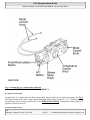
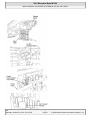
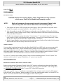
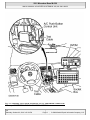
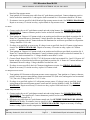
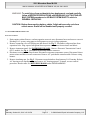
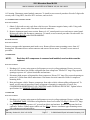
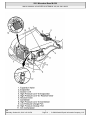
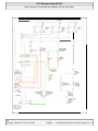
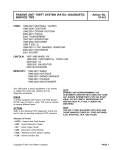
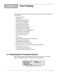
1
2001 Mercedes-Benz ML320 2000-01 MANUAL A/C-HEATER SYSTEMS ML 320, ML 430 & ML 55 2000-01 MANUAL A/C-HEATER SYSTEMS ML 320, ML 430 & ML 55 SPECIFICATIONS SPECIFICATIONS Application Compressor Type Specification Nippondenso 7SB16 7-Cyl. (1) Compressor Belt Tension (2) 5.6-6.3 ozs. Compressor Oil Capacity Refrigerant (R-134a) Capacity 26.4 ozs. System Operating Pressures (1) Belt tension is automatically adjusted by belt tensioner. (3) (2) Use Densooil 8 (A 001 989 08 03). (3) Information is not available from manufacturer. DESCRIPTION & OPERATION WARNING: To avoid injury from Accidental air bag deployment, read and carefully follow all SERVICE PRECAUTIONS and DISABLING & ACTIVATING AIR BAG SYSTEM procedures in AIR BAG SYSTEM SAFETY article in GENERAL SERVICING. A/C CONTROL PANEL The A/C control panel contains switches to control A/C functions such as blower motor speed, mode control, in-vehicle temperature, A/C on/off, and fresh/recirculated air control. See Fig. 1 . me Saturday, October 02, 2010 3:25:13 3:25:10 PM Page 1 © 2006 Mitchell Repair Information Company, LLC. 2001 Mercedes-Benz ML320 2000-01 MANUAL A/C-HEATER SYSTEMS ML 320, ML 430 & ML 55 Fig. 1: Identifying A/C Control Panel Functions Courtesy of MERCEDES-BENZ OF NORTH AMERICA BLOWER MOTOR KNOB Located in the A/C control panel, the blower motor knob controls blower motor speed in 4 settings. See Fig. 1 . The blower motor knob sends a voltage signal through the blower motor resistor in "1" to "3" positions and bypasses blower motor resistor in position No. 4. See WIRING DIAGRAMS . Setting blower motor knob to "0" position will turn system off. MODE CONTROL KNOB me Saturday, October 02, 2010 3:25:10 PM Page 2 © 2006 Mitchell Repair Information Company, LLC. 2001 Mercedes-Benz ML320 2000-01 MANUAL A/C-HEATER SYSTEMS ML 320, ML 430 & ML 55 Mode control knob controls air distribution throughout the passenger compartment. Air distribution doors are controlled by cables activated by the mode control knob. See Fig. 1 . Four mode positions are available with detents in-between to adjust airflow for personal comfort. Defrost Set mode control knob to 12-o'clock position. Air will exit from defrost outlets and side window vents. Vent Set mode control knob to 9-o'clock position. Air will exit from instrument panel outlets. Floor Set mode control knob to 6-o'clock position. Air will exit from floor outlets. Blend/Bi-Level Set mode control knob to 3-o'clock position. Air will exit from defrost, instrument panel, and floor outlets. TEMPERATURE CONTROL KNOB Air temperature is controlled by a variable resistor rotary control switch. See Fig. 1 . Switch receives voltage signal and depending upon position, controls voltage signal sent to air mix damper door motor. See Fig. 2 . Voltage controls position of motor for heating and cooling. me Saturday, October 02, 2010 3:25:10 PM Page 3 © 2006 Mitchell Repair Information Company, LLC. 2001 Mercedes-Benz ML320 2000-01 MANUAL A/C-HEATER SYSTEMS ML 320, ML 430 & ML 55 me Saturday, October 02, 2010 3:25:10 PM Page 4 © 2006 Mitchell Repair Information Company, LLC. 2001 Mercedes-Benz ML320 2000-01 MANUAL A/C-HEATER SYSTEMS ML 320, ML 430 & ML 55 Fig. 2: Locating Climate Control Components Courtesy of MERCEDES-BENZ OF NORTH AMERICA FRESH/RECIRCULATION SWITCH Fresh/recirculation switch controls voltage signal to fresh air recirculation door motor. See Fig. 1 and Fig. 2 . With switch indicator light on, air will recirculate. With switch indicator light off, air will enter from outside of vehicle. A/C CONTROL MODULE The A/C control module (A/C amplifier) is the control unit for the A/C system. See Fig. 2 . The module receives inputs from various sensors and processes the information to control various outputs for the A/C system for optimal control. The A/C control module inputs are as follows: A/C Switch In-Vehicle Air Temperature Sensor Temperature Selector Knob Blower Motor Knob Evaporator Temperature Sensor Air Mix Damper Door Position Sensor The A/C control module output functions are as follows: Air Mix Damper Door Motor All Activity Module Fresh/Recirculation Door Motor ALL ACTIVITY MODULE All Activity Module (AAM) receives inputs to determine if specified conditions have been met to allow operation of A/C-heater system. If conditions are met, the AAM will send signals to the A/C compressor, condenser fans relay and the blower motor relay to command or enable operation. IN-VEHICLE TEMPERATURE SENSOR The in-vehicle temperature sensor is a negative temperature coefficient resistor. Sensor sends signals to the A/C control module to maintain in-vehicle temperature. Sensor is located on the center panel of the instrument cluster. DUST FILTER A dust filter provides filtering of air entering or recirculating in the passenger's compartment. The dust filter is mounted between blower motor and evaporator, below passenger's side of instrument panel, to left of blower me Saturday, October 02, 2010 3:25:10 PM Page 5 © 2006 Mitchell Repair Information Company, LLC. 2001 Mercedes-Benz ML320 2000-01 MANUAL A/C-HEATER SYSTEMS ML 320, ML 430 & ML 55 motor. See Fig. 2 . PROGRAMMING RECODING RADIO CAUTION: Before disconnecting battery, obtain 5-digit radio security code from vehicle owner. Radio will be disabled until properly recoded. NOTE: Radio will not operate if power supply to radio is interrupted. Obtain 5-digit radio security code from vehicle owner before disconnecting battery. 1. Turn ignition on. Ensure CODE is displayed on radio display. Enter code numbers using radio station buttons. For example, use station button No. 1 for code No. 1 and so on. 2. After first number is entered, CODE disappears and number entered is displayed followed by 4 dashes. After entering 5-digits, confirm correct security code has been entered. If incorrect code has been entered, entire code must be reentered. 3. Confirm entry of correct security code using "<" (less than) or ">" (more than) buttons. If an incorrect code is entered, CODE will be displayed on radio display. If security code is entered incorrectly 3 times, WAIT will be displayed and radio will be disabled for about 10 minutes. 4. If, after 3 more attempts, correct security code has not been entered, radio will be disabled for 60 minutes. Radio disable time runs down only when radio is turned off. VERSION CODING Version coding is performed using a Mercedes-Benz Hand-Held Tester (HHT) and is on-screen menu guided. After connecting HHT to DLC, vehicle communication is possible as soon as ignition key is inserted into ignition switch (position of switch does not matter). Version coding menu, position 1, is reached via main menu and control module adaptation, position 5. There are 2 possible version codings available: readout of version code and transfer to new control module or readout of version code and to alter code. To access A/C system version coding, position 2 must be selected and then position 7 for A/C system. Two selections can be used: A/C system is installed or A/C system is not installed. SELF-DIAGNOSTICS RETRIEVING & ERASING DIAGNOSTIC TROUBLE CODES Retrieving and erasing of Diagnostic Trouble Codes (DTC) must be performed using Mercedes-Benz HandHeld Tester (HHT). See HHT instructions for retrieving A/C-heater system related DTC. After noting codes, see CLIMATE CONTROL DTC table. To erase DTC, follow HHT instructions. When retrieving DTC from A/C push button control module, short and open circuits cannot be differentiated from each other in every instance. When accessing DTC from any control module memory, all stored DTC are shown. As a result, some DTC shown will not apply to climate control system. me Saturday, October 02, 2010 3:25:10 PM Page 6 © 2006 Mitchell Repair Information Company, LLC. 2001 Mercedes-Benz ML320 2000-01 MANUAL A/C-HEATER SYSTEMS ML 320, ML 430 & ML 55 CLIMATE CONTROL DTC DTC B1232 Possible Cause (1) Refrigerant Pressure Sensor B1419 Electromagnetic Clutch (1) Check A/C refrigerant pressure sensor. See A/C REFRIGERANT PRESSURE SWITCH under ELECTRICAL TESTS. SYSTEM TESTS WARNING: To avoid injury from Accidental air bag deployment, read and carefully follow all SERVICE PRECAUTIONS and DISABLING & ACTIVATING AIR BAG SYSTEM procedures in AIR BAG SYSTEM SAFETY article in GENERAL SERVICING. CONNECTING TEST EQUIPMENT Remove radio to gain access to A/C push button control unit harness connector. Turn ignition off. Disconnect control unit harness connector. Connect socket box Test Cable (163 589 01 63 00) to A/C push button control unit and wiring harness. See Fig. 3 . Connect test cable to Socket Box (124 589 00 21 00). Connect test equipment leads to socket box terminals as instructed in circuit tests. me Saturday, October 02, 2010 3:25:10 PM Page 7 © 2006 Mitchell Repair Information Company, LLC. 2001 Mercedes-Benz ML320 2000-01 MANUAL A/C-HEATER SYSTEMS ML 320, ML 430 & ML 55 Fig. 3: Connecting Test Cable & Socket Box To A/C Push-Button Control Unit Courtesy of MERCEDES-BENZ OF NORTH AMERICA. me Saturday, October 02, 2010 3:25:10 PM Page 8 © 2006 Mitchell Repair Information Company, LLC. 2001 Mercedes-Benz ML320 2000-01 MANUAL A/C-HEATER SYSTEMS ML 320, ML 430 & ML 55 FUNCTIONAL TEST PREPARATION 1. Check condition of fuses F16, F41, F43 and F44. See WIRING DIAGRAMS . Repair and/or replace fuses and necessary. 2. Turn ignition on. Locate in-vehicle temperature sensor aspirator blower vent grille above anti-theft indicator light. Place a half-inch square of tissue paper over aspirator blower vent grille. If paper stays on vent grille, go to next step. If paper does not stay on vent grille, correct insufficient aspirator blower ventilation. 3. Put shift lever in "P" and engage parking brake. Run engine at idle until it reaches normal operating temperature, about 176°F (80°C). Ensure ambient (outside) temperature is greater than 58°F (15°C). 4. Manually open center and side air outlets. Ensure recirculation button is not depressed. Set blower speed knob to position No. 1. FUNCTION TEST NOTE: Function test steps must be performed in order given. Defrost Mode To check operation in defrost mode, set temperature selector knob to White range (vertical). Set mode control knob to 12-o'clock position (vertical). Ensure A/C button indicator is illuminated. Air will vent from defrost and center outlets and A/C compressor will engage. If operation is not as specified, perform the following in order: Check voltage supply circuit Z50/2 between No. 16 fuse (15-amp) and connected components. See VOLTAGE SUPPLY CIRCUIT Z50/2 under ELECTRICAL TESTS. Check ground circuit. See GROUND CIRCUIT Z50/4 under ELECTRICAL TESTS. Check in-vehicle temperature sensor signal voltage. See IN-VEHICLE TEMPERATURE SENSOR under ELECTRICAL TESTS. Check in-vehicle temperature sensor signal resistance. See IN-VEHICLE TEMPERATURE SENSOR under ELECTRICAL TESTS. Check icing protection temperature sensor signal voltage. See ICING PROTECTION TEMPERATURE SENSOR under ELECTRICAL TESTS. Check icing protection temperature sensor resistance. See ICING PROTECTION TEMPERATURE SENSOR under ELECTRICAL TESTS. Check activation voltage during temperature reduction. See ACTIVATION VOLTAGE TEMPERATURE under ELECTRICAL TESTS. Check activation voltage during temperature increase. See ACTIVATION VOLTAGE TEMPERATURE under ELECTRICAL TESTS. Check blend air flap actuator motor operation voltage. See BLEND AIR FLAP ACTUATOR MOTOR under ELECTRICAL TESTS. Check blend air flap actuator motor resistance. See BLEND AIR FLAP ACTUATOR MOTOR under ELECTRICAL TESTS. Check A/C button activation. See A/C BUTTON under ELECTRICAL TESTS. Check A/C pressure switch. See A/C REFRIGERANT PRESSURE SWITCH under ELECTRICAL me Saturday, October 02, 2010 3:25:10 PM Page 9 © 2006 Mitchell Repair Information Company, LLC. 2001 Mercedes-Benz ML320 2000-01 MANUAL A/C-HEATER SYSTEMS ML 320, ML 430 & ML 55 TESTS. Normal Ventilation In Regulating Mode To check normal ventilation in regulating mode, set temperature selector knob to White range (vertical). Set mode control knob to 4-o'clock position. Ensure A/C button indicator is illuminated. Air will vent from upper and lower outlets and A/C compressor will engage. Ambient air will flow from center outlet and coolant circulation pump will operate. If operation is not as specified, perform the following in order: Check A/C button activation. See A/C BUTTON under ELECTRICAL TESTS. Check A/C pressure switch. See A/C REFRIGERANT PRESSURE SWITCH under ELECTRICAL TESTS. Economy Setting Not In Heating Mode To check economy setting without heating mode activated, set temperature selector knob to Blue range. Set mode control knob to the 9-o'clock position. Ensure A/C button indicator is not illuminated. Ambient air will flow from center outlet and A/C compressor will NOT be engaged. If operation is not as specified, perform the following: Check A/C button activation. See A/C BUTTON under ELECTRICAL TESTS. Economy Setting In Heating Mode To check economy setting with heating mode activated, set temperature selector knob to Red range. Set mode control knob to the 4-o'clock position. Ensure A/C button indicator is not illuminated. Heated air will flow from lower, upper and center outlets and A/C compressor will NOT be engaged. If operation is not as specified, perform the following: Check A/C button activation. See A/C BUTTON under ELECTRICAL TESTS. Recirculation Mode To check recirculation mode, press fresh/recirculation button. Ensure fresh/recirculation indicator is illuminated. Set blower speed knob to position No. 4. Blower fan noise will increase noticeably. If operation is not as specified, check wiring between recirculated air flap element, heater-A/C switch and No. 16 fuse (15amp). ELECTRICAL TESTS Voltage Supply Circuit Z50/2 1. Connect socket box to A/C push button control unit and wiring harness. See CONNECTING TEST EQUIPMENT . Turn ignition on, with engine off. Connect voltmeter positive lead to socket box terminal No. 7 and negative lead to terminal No. 9. 2. Voltage should be 11-14 volts. If voltage is not as specified, check voltage supply circuit Z50/2 between No. 16 fuse (15-amp) and connected components. See WIRING DIAGRAMS . Repair as necessary. me Saturday, October 02, 2010 3:25:10 PM Page 10 © 2006 Mitchell Repair Information Company, LLC. 2001 Mercedes-Benz ML320 2000-01 MANUAL A/C-HEATER SYSTEMS ML 320, ML 430 & ML 55 Ground Circuit Z50/4 1. Connect socket box to A/C push button control unit wiring harness connector. See CONNECTING TEST EQUIPMENT . Turn ignition off. Ensure A/C push button control unit is not connected to socket box. 2. Connect ohmmeter positive lead to socket box terminal No. 9 and negative lead to body ground. Resistance should be zero. If resistance is not as specified, check control unit ground circuit Z50/4. See WIRING DIAGRAMS . Repair as necessary. In-Vehicle Temperature Sensor 1. Connect socket box to A/C push button control unit and wiring harness. See CONNECTING TEST EQUIPMENT . Connect voltmeter positive lead to socket box terminal No. 12 and negative lead to terminal No. 9. 2. Turn ignition on. Turn temperature control knob to Red range detent. Voltage should be 1.9 volts at 68°F (20°C). If voltage is as specified, go to next step. If voltage is not as specified, check in-vehicle temperature sensor circuits. See WIRING DIAGRAMS . Repair as necessary. If circuits are okay, replace in-vehicle temperature sensor. 3. Turn ignition off. Disconnect test cable from A/C push button control unit. Connect ohmmeter positive lead to socket box terminal No. 2 and negative lead to terminal No. 12. Measure temperature sensor resistance at specified temperatures. See IN-VEHICLE TEMPERATURE SENSOR RESISTANCE table. 4. If resistance is not as specified, check wiring harness and connectors between A/C push button control unit, in-vehicle temperature sensor, blend air flap actuator position sensor and temperature regulator switch. Repair as necessary. IN-VEHICLE TEMPERATURE SENSOR RESISTANCE Sensor Temperature - °F (°C) 68 (20) 77 (25) 104 (40) Ohms 2100 1700 900 Icing Protection Temperature Sensor 1. Connect socket box to A/C push button control unit and wiring harness. See CONNECTING TEST EQUIPMENT . Connect voltmeter positive lead to socket box terminal No. 11 and negative lead to terminal No. 9. 2. Turn ignition on. Voltage should be 2.0-2.4 volts at 32°F (0°C) and 1.4-1.8 volts at 59°F (15°C). If voltage is as specified, go to next step. If voltage is not as specified, check icing protection temperature sensor circuits. See WIRING DIAGRAMS . Repair as necessary. If circuits are okay, replace icing protection temperature sensor. 3. Turn ignition off. Disconnect test cable from A/C push button control unit. Connect ohmmeter positive lead to socket box terminal No. 3 and negative lead to terminal No. 11. Measure temperature sensor resistance at specified temperatures. See ICING PROTECTION TEMPERATURE SENSOR RESISTANCE table. me Saturday, October 02, 2010 3:25:10 PM Page 11 © 2006 Mitchell Repair Information Company, LLC. 2001 Mercedes-Benz ML320 2000-01 MANUAL A/C-HEATER SYSTEMS ML 320, ML 430 & ML 55 4. If resistance is not as specified, check wiring harness between temperature sensor and control unit. Repair as necessary. If wiring harness is okay, replace icing protection temperature sensor. ICING PROTECTION TEMPERATURE SENSOR RESISTANCE Sensor Temperature - °F (°C) 43 (6) 59 (15) 72 (22) 77 (25) Ohms 3600 2300 1700 1500 Activation Voltage Temperature 1. Connect socket box to A/C push button control unit and wiring harness. See CONNECTING TEST EQUIPMENT . Connect voltmeter positive lead to socket box terminal No. 2 and negative lead to terminal No. 9. 2. Turn ignition on. Turn temperature control knob to Blue range detent. Voltage should be more than 2.0 volts. Turn temperature control knob from Blue range detent to Red range detent. Voltage should be more than 3.0 volts. 3. If voltage is as specified, go to next step. If voltage is not as specified, check recirculated air switch circuits. See WIRING DIAGRAMS . Repair as necessary. If circuits are okay, replace recirculated air switch. 4. Connect voltmeter positive lead to socket box terminal No. 5 and negative lead to terminal No. 9. Turn ignition on. Turn temperature control knob to Blue range detent. Voltage should be more than 3.0 volts. Turn temperature control knob from Blue range detent to Red range detent. Voltage should be more than 4.0 volts. 5. If voltage is not as specified, check recirculated air switch circuits. See WIRING DIAGRAMS . Repair as necessary. If circuits are okay, replace recirculated air switch. Blend Air Flap Actuator Motor 1. Connect socket box to A/C push button control unit and wiring harness. See CONNECTING TEST EQUIPMENT . Connect voltmeter positive lead to socket box terminal No. 1 and negative lead to terminal No. 9. 2. Turn ignition on. Turn temperature control knob to Blue range detent. Voltage should be less than one volt. Turn temperature control knob from Blue range detent to Red range detent. Voltage should be 11.014.0 volts. 3. If voltage is as specified, go to next step. If voltage is not as specified, check blend air flap actuator motor wiring harness circuits. See WIRING DIAGRAMS . Repair as necessary. If circuits are okay, replace blend air flap actuator motor. 4. Connect voltmeter positive lead to socket box terminal No. 8 and negative lead to terminal No. 9. Turn ignition on. Turn temperature control knob to Red range detent. Voltage should be less than one volt. Turn temperature control knob from Red range detent to Blue range detent. Voltage should be 11.0-14.0 volts. 5. If voltage is as specified, go to next step. If voltage is not as specified, check blend air flap actuator motor wiring harness circuits. See WIRING DIAGRAMS . Repair as necessary. If circuits are okay, replace me Saturday, October 02, 2010 3:25:10 PM Page 12 © 2006 Mitchell Repair Information Company, LLC. 2001 Mercedes-Benz ML320 2000-01 MANUAL A/C-HEATER SYSTEMS ML 320, ML 430 & ML 55 blend air flap actuator motor. 6. Turn ignition off. Disconnect test cable from A/C push button control unit. Connect ohmmeter positive lead to socket box terminal No. 1 and negative lead to terminal No. 8. Resistance should be 120 ohms. 7. If resistance is not as specified, check blend air flap actuator motor circuits. See WIRING DIAGRAMS . Repair as necessary. If circuits are okay, replace blend air flap actuator motor. A/C Button 1. Connect socket box to A/C push button control unit and wiring harness. See CONNECTING TEST EQUIPMENT . Connect voltmeter positive lead to socket box terminal No. 10 and negative lead to terminal No. 9. 2. Turn ignition on. Depress A/C button switch to on position and set blower speed knob to position No. 4. Ensure A/C button indicator is illuminated. Voltage should be less than one volt. Depress A/C button switch to off position with A/C button indicator not illuminated or set blower speed knob to off position. Voltage should be 11-14 volts. 3. If voltage is as specified, go to next step. If voltage is not as specified, check A/C button wiring harness circuits. See WIRING DIAGRAMS . Repair as necessary. If circuits are okay, replace A/C button switch. 4. Turn ignition on. Depress A/C button switch to on position and set blower speed knob to position No. 4. Ensure A/C button indicator is illuminated. Connect voltmeter positive lead to socket box terminal No. 4 and negative lead to terminal No. 9. Voltage should be more than 3.0 volts. 5. Connect Fused Jumper Wire (124 589 37 63 00) between socket box terminals No. 4 and 11. Depress A/C button switch to on position and set blower speed knob to position No. 4. Ensure A/C button indicator is illuminated. Measure voltage. Voltage should be less than one volt. 6. If voltage is not as specified, check A/C button wiring harness circuits. See WIRING DIAGRAMS . Repair as necessary. If circuits are okay, replace A/C button switch. A/C Refrigerant Pressure Switch 1. Turn ignition off. Disconnect refrigerant pressure sensor connector. Turn ignition on. Connect voltmeter positive lead to pressure sensor harness connector terminal "B" (Pink wire) and negative lead to terminal "A" (Tan wire). Voltage should be 4.75-5.25 volts. 2. If voltage is as specified, replace A/C refrigerant pressure sensor. If voltage is not as specified, check wiring harness between refrigerant pressure sensor and All Activity Module (AAM). See WIRING DIAGRAMS . Repair as necessary. If circuits are okay, replace AAM and retest A/C system. Outside Temperature Sensor 1. Connect socket box to A/C push button control unit and wiring harness. See CONNECTING TEST EQUIPMENT . Turn ignition off. Connect ohmmeter positive lead to socket box terminal No. 12 and negative lead to terminal No. 3. 2. Disconnect test cable from A/C push button control unit. See OUTSIDE TEMPERATURE SENSOR RESISTANCE table. If resistance is not as specified, check wiring harness between outside temperature sensor and A/C push button control unit. See WIRING DIAGRAMS . Repair as necessary. If wiring harness is okay, replace outside temperature sensor. me Saturday, October 02, 2010 3:25:10 PM Page 13 © 2006 Mitchell Repair Information Company, LLC. 2001 Mercedes-Benz ML320 2000-01 MANUAL A/C-HEATER SYSTEMS ML 320, ML 430 & ML 55 OUTSIDE TEMPERATURE SENSOR RESISTANCE Sensor Temperature - °F (°C) 68 (20) 77 (25) 104 (40) 122 (50) Ohms 2100 1700 900 600 READING ACTUAL VALUES WITH HHT Connect Hand-Held Tester (HHT) to DLC and follow displayed procedures. Actual values displayed on HHT show normal operation value of A/C systems or components. See ACTUAL VALUES table. If value is not as specified, check system or components in order. Repair as necessary. ACTUAL VALUES Step (1) 01 02 03 04 05 08 Test Condition Value System/Component ..... 11-14 Volts Engine Operating At Normal Temperature Ignition ON About 176°F (80°C) Ignition ON ON/OFF Ambient Air Temperature About 68°F (20°C) Ignition ON, Blower At ON/OFF Stage 4 Ignition ON ON/OFF 09 Engine On, A/C Indicator Refrigerant Pressure At On, Blower Motor At 174 psi (12 bar) Stage 4 10 Engine On, A/C Indicator ON/OFF On, Blower Motor At Stage 4 11 Ignition ON, Activate YES/NO A/C System (1) Step numbers not shown are not used. Voltage Supply Wiring (Circuit No. 30) & Battery Wiring, ECT Sensor & AAM Wiring, Outside Temperature Sensor & AAM Wiring, Blower Motor Relay, Blower Motor & AAM Wiring, Engine Cooling Fan Stage 1, Aux. Fan & AAM Wiring, Coolant Circulation Pump Relay, Coolant Circulation Pump & AAM (2) Refrigerant Pressure Sensor (3) AAM, A/C Compressor Wiring, A/C Push Button Control Module, AAM (2) Check A/C refrigerant pressure switch. See A/C REFRIGERANT PRESSURE SWITCH under ELECTRICAL TESTS. (3) Check A/C button activation. See A/C BUTTON under ELECTRICAL TESTS. REMOVAL & INSTALLATION me Saturday, October 02, 2010 3:25:10 PM Page 14 © 2006 Mitchell Repair Information Company, LLC. 2001 Mercedes-Benz ML320 2000-01 MANUAL A/C-HEATER SYSTEMS ML 320, ML 430 & ML 55 WARNING: To avoid injury from accidental air bag deployment, read and carefully follow all SERVICE PRECAUTIONS and DISABLING & ACTIVATING AIR BAG SYSTEM procedures in AIR BAG SYSTEM SAFETY article in GENERAL SERVICING. CAUTION: Before disconnecting battery, obtain 5-digit radio security code from vehicle owner. Radio will be disabled until properly recoded. A/C EVAPORATOR HOUSING UNIT Removal & Installation 1. Drain engine coolant. Remove coolant expansion reservoir nuts, disconnect hoses and remove reservoir. Discharge A/C system, using approved refrigerant recovery/recycling equipment. 2. Remove expansion valve self-locking nut and discard. See Fig. 5 . Disconnect refrigerant lines from expansion valve. Plug exposed refrigerant lines to protect A/C system from moisture and debris. 3. Remove instrument panel. See INSTRUMENT PANEL . Remove Electronic Transmission Control (ETC) module. See Fig. 4 . Disconnect air mix flap actuator connector. 4. Disconnect recirculated air flap element. Disconnect evaporator temperature sensor. Disconnect blower motor resistor and blower motor connectors. Remove A/C push button control module. Release wiring harness. 5. Remove insulating mat. See Fig. 5 . Disconnect water drain hose from bottom of A/C housing. Release A/C housing-to-air distributor clips and remove A/C housing upward. To install, reverse removal procedure. Recode radio. See RECODING RADIO under PROGRAMMING. me Saturday, October 02, 2010 3:25:10 PM Page 15 © 2006 Mitchell Repair Information Company, LLC. 2001 Mercedes-Benz ML320 2000-01 MANUAL A/C-HEATER SYSTEMS ML 320, ML 430 & ML 55 Fig. 4: Removing Evaporator Housing Unit Courtesy of MERCEDES-BENZ OF NORTH AMERICA. A/C MIX FLAP ACTUATOR Removal & Installation Remove instrument panel. See INSTRUMENT PANEL . Disconnect air mix flap actuator connector. Remove 3 screws and remove air mix flap actuator. To install reverse removal procedure. A/C PUSH BUTTON CONTROL MODULE Removal & Installation Disconnect negative battery cable. Remove A/C push button control panel. See A/C PUSH BUTTON CONTROL PANEL . Remove 4 A/C push button control module screws and remove control module from me Saturday, October 02, 2010 3:25:10 PM Page 16 © 2006 Mitchell Repair Information Company, LLC. 2001 Mercedes-Benz ML320 2000-01 MANUAL A/C-HEATER SYSTEMS ML 320, ML 430 & ML 55 A/C housing. Disconnect control module connector. To install reverse removal procedure. Recode 5-digit radio security code. Using HHT, check for DTC and erase, and set clock. A/C PUSH BUTTON CONTROL PANEL Removal & Installation 1. Obtain 5-digit radio security code from vehicle owner. Disconnect negative battery cable. Using radio removal plates, remove radio. Disconnect electrical connectors. 2. Remove instrument panel center section. Remove 4 A/C control panel screws and remove control panel. Release pull cables and disconnect connectors. To install, reverse removal procedure. Recode radio. See RECODING RADIO under PROGRAMMING. BLOWER MOTOR Removal & Installation Remove passenger-side instrument panel under cover. Remove blower motor mounting screws from A/C housing unit. Disconnect blower motor connector and remove blower motor. To install, reverse removal procedure. COMPRESSOR NOTE: Each time A/C compressor is removed and installed, receiver-drier must be replaced. Removal & Installation 1. Discharge A/C system, using approved refrigerant recovery/recycling equipment. Remove accessory drive belt. Disconnect low pressure refrigerant line from compressor. Discard "O" rings. Plug exposed openings to protect A/C system from debris and moisture. 2. Disconnect high pressure refrigerant line from compressor. Discard "O" rings. Plug exposed openings to protect A/C system from debris and moisture. Disconnect electrical connector. Remove compressor mounting bolts. 3. Raise and support vehicle. Remove compressor from under vehicle without spilling refrigerant oil. To install, reverse removal procedure. Ensure refrigerant oil quantity in compressor is correct. See COMPRESSOR REFRIGERANT OIL CHECKING under GENERAL SERVICING. Tighten bolts to specification. See TORQUE SPECIFICATIONS . CONDENSER Removal & Installation 1. Discharge A/C system, using approved refrigerant recovery/recycling equipment. Remove cooling fans. See COOLING FANS . Disconnect refrigerant line from receiver-drier. See Fig. 5 . Discard "O" rings. 2. Plug exposed openings to protect A/C system from debris and moisture. Remove refrigerant line from condenser. Remove radiator upper rubber seal. See Fig. 6 . Remove condenser upper mounting screws. Lift condenser upward and remove. me Saturday, October 02, 2010 3:25:10 PM Page 17 © 2006 Mitchell Repair Information Company, LLC. 2001 Mercedes-Benz ML320 2000-01 MANUAL A/C-HEATER SYSTEMS ML 320, ML 430 & ML 55 3. To install, reverse removal procedure. Use NEW "O" rings lubricated with refrigerant oil. If installing a new or repaired condenser, add 0.68 ounce of NEW refrigerant oil to condenser. Tighten refrigerant line bolts to specification. See TORQUE SPECIFICATIONS . me Saturday, October 02, 2010 3:25:10 PM Page 18 © 2006 Mitchell Repair Information Company, LLC. 2001 Mercedes-Benz ML320 2000-01 MANUAL A/C-HEATER SYSTEMS ML 320, ML 430 & ML 55 me Saturday, October 02, 2010 3:25:10 PM Page 19 © 2006 Mitchell Repair Information Company, LLC. 2001 Mercedes-Benz ML320 2000-01 MANUAL A/C-HEATER SYSTEMS ML 320, ML 430 & ML 55 Fig. 5: Locating A/C Refrigerant System Components Courtesy of MERCEDES-BENZ OF NORTH AMERICA. me Saturday, October 02, 2010 3:25:10 PM Page 20 © 2006 Mitchell Repair Information Company, LLC. 2001 Mercedes-Benz ML320 2000-01 MANUAL A/C-HEATER SYSTEMS ML 320, ML 430 & ML 55 Fig. 6: Removing Cooling Fans & Condenser Courtesy of MERCEDES-BENZ OF NORTH AMERICA. COOLING FANS Removal & Installation Remove headlight units. Remove upper frame crossmember, release hood release control cable and remove crossmember. See Fig. 6 . Remove 2 cooling fans frame bolts on radiator. Disconnect cooling fan connector. Release outside temperature sensor wiring harness. Pull up on cooling fan and remove. To install, reverse removal procedure. Ensure cooling fan bottom guides are properly seated in lower mounts. EVAPORATOR Removal & Installation Remove A/C housing unit. See A/C HOUSING UNIT . Remove expansion valve. See Fig. 5 . Discard "O" rings. Disassemble A/C housing unit. Remove evaporator. Remove evaporator temperature sensor. To install, reverse removal procedure. Use NEW "O" rings lubricated with refrigerant oil. If installing a new or repair evaporator, add 1.35 ounces of NEW refrigerant oil to evaporator. EXPANSION VALVE Removal & Installation 1. Discharge A/C system, using approved refrigerant recovery/recycling equipment. Without disconnecting coolant hoses, remove coolant expansion reservoir and set aside. Remove refrigerant line bracket and loosen clamps. See Fig. 5 . Pull refrigerant lines out of expansion valve. 2. Remove expansion valve self-locking nut and discard. Remove expansion valve. Discard "O" rings. To install, reverse removal procedure. Use NEW "O" rings lubricated with refrigerant oil. Tighten NEW selflocking nut to specification. See TORQUE SPECIFICATIONS . INSTRUMENT PANEL & INSTRUMENT PANEL CARRIER Removal & Installation 1. Secure vehicle against rolling. Set transmission selector to "D" position. Obtain radio security code. Disconnect negative battery cable. Remove driver-side air bag. 2. Place match marks on steering wheel and steering shaft. Remove steering wheel, upper steering column covers and combination switch. Remove instrument cluster cover frame. Remove one instrument panel lower section bolt. 3. Remove screws in footwell from left side of instrument panel bottom section. Remove instrument panel center section. Remove 4 A/C control panel screws and remove control panel. See Fig. 1 . Release pull cables and disconnect connectors. 4. Remove screws from center section. Remove glove box. Remove screws in footwell from right side of instrument panel bottom section. Remove entry courtesy lights. Remove end covers and screws. 5. Release 4 "A" clips between instrument panel bottom section and upper section. See Fig. 7 . Release parking brake release cable from handle. With assistance, remove instrument panel bottom section. me Saturday, October 02, 2010 3:25:10 PM Page 21 © 2006 Mitchell Repair Information Company, LLC. 2001 Mercedes-Benz ML320 2000-01 MANUAL A/C-HEATER SYSTEMS ML 320, ML 430 & ML 55 6. Remove A-pillar panel trim. Remove instrument cluster. Remove defroster vent cover. Remove air vents and side air nozzles. With assistance, remove upper instrument panel. 7. Remove passenger-side air bag. Remove right side lower instrument panel cover. Remove instrument panel carrier screws from A/C housing unit. Remove left side lower instrument panel cover. 8. Remove insulating mat between steering column and instrument panel carrier. Remove steering column bolts and nuts from instrument panel carrier. See Fig. 8 . Remove instrument panel carrier center tunnel bolts. Disconnect steering column connectors. 9. Remove wiring harness from instrument panel carrier. Remove wiper washer system. Remove instrument panel carrier nuts from engine compartment side of firewall. 10. Remove A-pillar bolt covers and remove instrument panel carrier A-pillar bolts. With assistance, remove instrument panel carrier through passenger door. To install, reverse removal procedure. 11. Ensure instrument panel bottom section guide tongues "B" are seated into instrument panel upper section mounts. See Fig. 8 . Tighten nuts and bolts to specification. See TORQUE SPECIFICATIONS . Recode radio. See RECODING RADIO under PROGRAMMING. Fig. 7: Removing Instrument Panel Bottom Section Courtesy of MERCEDES-BENZ OF NORTH AMERICA. me Saturday, October 02, 2010 3:25:10 PM Page 22 © 2006 Mitchell Repair Information Company, LLC. 2001 Mercedes-Benz ML320 2000-01 MANUAL A/C-HEATER SYSTEMS ML 320, ML 430 & ML 55 Fig. 8: Removing Instrument Panel Upper Section & Instrument Panel Carrier Courtesy of MERCEDES-BENZ OF NORTH AMERICA. INTAKE AIR DUST FILTER Removal & Installation Remove passenger-side instrument panel lower trim panel. Release retaining clip and remove dust filter cover. Pull dust filter down and out. See Fig. 9 . To install, reverse removal procedure. me Saturday, October 02, 2010 3:25:10 PM Page 23 © 2006 Mitchell Repair Information Company, LLC. 2001 Mercedes-Benz ML320 2000-01 MANUAL A/C-HEATER SYSTEMS ML 320, ML 430 & ML 55 me Saturday, October 02, 2010 3:25:10 PM Page 24 © 2006 Mitchell Repair Information Company, LLC. 2001 Mercedes-Benz ML320 2000-01 MANUAL A/C-HEATER SYSTEMS ML 320, ML 430 & ML 55 Fig. 9: Replacing Intake Air Dust Filter Courtesy of MERCEDES-BENZ OF NORTH AMERICA. RECEIVER-DRIER Removal & Installation 1. Discharge A/C system, using approved refrigerant recovery/recycling equipment. Remove headlight units. Remove headlight units. Remove upper frame crossmember, release hood release control cable and remove crossmember. See Fig. 6 . 2. Remove bolts from receiver-drier refrigerant lines. See Fig. 5 . Disconnect refrigerant lines from receiverdrier. Plug exposed openings to protect A/C system from debris and moisture. Discard "O" rings. Loosen receiver-drier clamp bolt. Remove receiver-drier. To install, reverse removal procedure. 3. When installing a new receiver-drier, add 0.34 ounce of NEW refrigerant oil to receiver-drier. Use NEW "O" rings. Tighten refrigerant line bolts to specification. See TORQUE SPECIFICATIONS . TORQUE SPECIFICATIONS TORQUE SPECIFICATIONS Application Compressor Mounting Bolts Refrigerant Line-To-Compressor Bolt Refrigerant Line-To-Condenser Bolt Steering Column Bolt Steering Column Nut Ft. Lbs. (N.m) 15 (20) 15 (20) 15 (20) 15 (20) 13 (18) INCH Lbs. (N.m) 89 (10) 89 (10) Expansion Valve Self-Locking Nut Refrigerant Line-To-Receiver-Drier Bolt WIRING DIAGRAMS me Saturday, October 02, 2010 3:25:10 PM Page 25 © 2006 Mitchell Repair Information Company, LLC. 2001 Mercedes-Benz ML320 2000-01 MANUAL A/C-HEATER SYSTEMS ML 320, ML 430 & ML 55 me Saturday, October 02, 2010 3:25:10 PM Page 26 © 2006 Mitchell Repair Information Company, LLC. 2001 Mercedes-Benz ML320 2000-01 MANUAL A/C-HEATER SYSTEMS ML 320, ML 430 & ML 55 Fig. 10: Manual A/C-Heater Systems Wiring Diagram (2000-01 ML 320 Without Cooling Fan Control Module - 1 Of 2) me Saturday, October 02, 2010 3:25:10 PM Page 27 © 2006 Mitchell Repair Information Company, LLC. 2001 Mercedes-Benz ML320 2000-01 MANUAL A/C-HEATER SYSTEMS ML 320, ML 430 & ML 55 me Saturday, October 02, 2010 3:25:10 PM Page 28 © 2006 Mitchell Repair Information Company, LLC. 2001 Mercedes-Benz ML320 2000-01 MANUAL A/C-HEATER SYSTEMS ML 320, ML 430 & ML 55 Fig. 11: Manual A/C-Heater Systems Wiring Diagram (2000-01 ML 320 Without Cooling Fan Control Module - 2 Of 2) me Saturday, October 02, 2010 3:25:10 PM Page 29 © 2006 Mitchell Repair Information Company, LLC. 2001 Mercedes-Benz ML320 2000-01 MANUAL A/C-HEATER SYSTEMS ML 320, ML 430 & ML 55 me Saturday, October 02, 2010 3:25:10 PM Page 30 © 2006 Mitchell Repair Information Company, LLC. 2001 Mercedes-Benz ML320 2000-01 MANUAL A/C-HEATER SYSTEMS ML 320, ML 430 & ML 55 Fig. 12: Automatic A/C-Heater Systems Wiring Diagram (2000-01 ML 320 & ML 430 With Cooling Fan Control Module - 1 Of 2) me Saturday, October 02, 2010 3:25:10 PM Page 31 © 2006 Mitchell Repair Information Company, LLC. 2001 Mercedes-Benz ML320 2000-01 MANUAL A/C-HEATER SYSTEMS ML 320, ML 430 & ML 55 me Saturday, October 02, 2010 3:25:10 PM Page 32 © 2006 Mitchell Repair Information Company, LLC. 2001 Mercedes-Benz ML320 2000-01 MANUAL A/C-HEATER SYSTEMS ML 320, ML 430 & ML 55 Fig. 13: Automatic A/C-Heater Systems Wiring Diagram (2000-01 ML 320 & ML 430 With Cooling Fan Control Module - 2 Of 2) me Saturday, October 02, 2010 3:25:10 PM Page 33 © 2006 Mitchell Repair Information Company, LLC.