1
instruction manual
AXP-AI8
Eight-Channel Analog Input
Interface Board
C u s t o m Pa n e l I n t e r f a c e s
AMX Limited Warranty and Disclaimer
AMX Corporation warrants its products to be free of defects in material and workmanship under normal use for
three (3) years from the date of purchase from AMX Corporation, with the following exceptions:
•
Electroluminescent and LCD Control Panels are warranted for three (3) years, except for the display and touch
overlay components that are warranted for a period of one (1) year.
•
Disk drive mechanisms, pan/tilt heads, power supplies, MX Series products, and KC Series products are
warranted for a period of one (1) year.
•
Unless otherwise specified, OEM and custom products are warranted for a period of one (1) year.
•
Software is warranted for a period of ninety (90) days.
•
Batteries and incandescent lamps are not covered under the warranty.
This warranty extends only to products purchased directly from AMX Corporation or an Authorized AMX Dealer.
AMX Corporation is not liable for any damages caused by its products or for the failure of its products to perform.
This includes any lost profits, lost savings, incidental damages, or consequential damages. AMX Corporation is not
liable for any claim made by a third party or by an AMX Dealer for a third party.
This limitation of liability applies whether damages are sought, or a claim is made, under this warranty or as a tort
claim (including negligence and strict product liability), a contract claim, or any other claim. This limitation of
liability cannot be waived or amended by any person. This limitation of liability will be effective even if AMX
Corporation or an authorized representative of AMX Corporation has been advised of the possibility of any such
damages. This limitation of liability, however, will not apply to claims for personal injury.
Some states do not allow a limitation of how long an implied warranty last. Some states do not allow the limitation or
exclusion of incidental or consequential damages for consumer products. In such states, the limitation or exclusion of
the Limited Warranty may not apply. This Limited Warranty gives the owner specific legal rights. The owner may
also have other rights that vary from state to state. The owner is advised to consult applicable state laws for full
determination of rights.
EXCEPT AS EXPRESSLY SET FORTH IN THIS WARRANTY, AMX CORPORATION MAKES NO
OTHER WARRANTIES, EXPRESSED OR IMPLIED, INCLUDING ANY IMPLIED WARRANTIES OF
MERCHANTABILITY OR FITNESS FOR A PARTICULAR PURPOSE. AMX CORPORATION
EXPRESSLY DISCLAIMS ALL WARRANTIES NOT STATED IN THIS LIMITED WARRANTY. ANY
IMPLIED WARRANTIES THAT MAY BE IMPOSED BY LAW ARE LIMITED TO THE TERMS OF THIS
LIMITED WARRANTY.
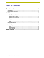
Table of Contents
Table of Contents
Product Information .................................................................................................1
Specifications .................................................................................................................... 1
Dimensions and Descriptions............................................................................................ 2
Installation .................................................................................................................3
Configuring Switches......................................................................................................... 3
Setting the Device DIP Switch ................................................................................................. 3
Setting the input SIP switch ..................................................................................................... 3
Setting the joystick range POTs............................................................................................... 3
Wiring ....................................................................................................................................... 4
20-Pin Header .......................................................................................................................... 4
AXlink ....................................................................................................................................... 4
Configuring the AXP-AI8 ................................................................................................... 5
Testing ..................................................................................................................................... 5
Programming..................................................................................................................... 6
Levels....................................................................................................................................... 6
Send_Commands .................................................................................................................... 6
Sample Application .................................................................................................................. 6
System Worksheet ...................................................................................................9
AXP-AI8 Eight-Channel Analog Interface Board
i
Table of Contents
ii
AXP-AI8 Eight-Channel Analog Interface Board
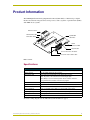
Product Information
Product Information
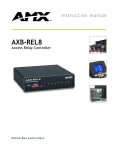
The AMX Eight-Channel Analog Input Interface Board (AXP-AI8) is a 10-bit analog-to-digital
interface board used to integrate remote analog sources, such as joysticks or potentiometers (POTs),
with AMX Axcess systems.
AXLink connector
AXLink Status LED
Input On/Off
SIP Switch
Device DIP Switch
HI/LO
Reference POTs
20-pin Header
Connect this side to PC board.
Connect this side to ribbon cable.
FIG. 1 AXP-AI8
Specifications
Specifications
20-pin Berg header
Connects to either a ribbon cable (up to 30 feet) or mounts directly into a PC.
AXlink connector
A 4-wire AXlink data/power bus operation.
AXlink Status LED
Green LED shows AXlink data activity. Blink patterns include:
• Off - No power, or the controller is not functioning properly.
• One blink per second - Normal operation. Device numbers match the
programmed device numbers in the Axcess program.
Cables
3 feet (91.4 cm) of ribbon cable with a female 20-pin header.
Device DIP Switch
8-position device DIP Switch to set the AXP-AI8 as an AXlink device.
POTs
HI and LO reference POTs maximize the resolution of joystick operation.
Power requirement
Inputs accept POTs (5K to 100K) or an external DC voltage (0-5V).
Input voltage range
Input voltage range of 0 to +5volts (maximum input voltage is +5volts)
Signal Inputs
8 analog inputs, measured with 10 bit resolution.
SIP Switch
8-position SIP Switch to turn off unused inputs.
To create a wiring diagram, use the AXP-AI8 System Worksheet on page 7.
AXP-AI8 Eight-Channel Analog Interface Board
1
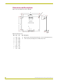
Product Information
Dimensions and Descriptions
FIG. 2 shows the dimensions of the AXP-AI8:
H
B
C
A
AXlink
AXlink
L
PWR AXP AXM GND
A
P1
Top View
(Component Side)
D
E
G
2
1
F
P2
A
20
19
J
K
min
FIG. 2 AXP-AI8 dimensions
2
Item
Inch
mm
A
0.20
5.10
G
20-Pin Header - .025 inch (6 mm) square pins, .1 inch (2.4 mm) typical spacing.
H
.125 inch (3.2 mm) mounting holes for #4-40 (3 mm) screws.
B
3.50
88.90
C
3.10
78.70
D
2.75
69.90
E
2.35
59.70
F
1.10
27.94
J
0.23
5.80
K
0.438 11.10
L
0.93
Item Description
23.60
AXP-AI8 Eight-Channel Analog Interface Board
Installation
Installation
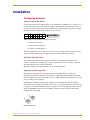
Configuring Switches
Setting the Device DIP Switch
Use the eight-position device DIP switch to set the AXP-AI8 as an AXlink device. It can be one of
255 devices in an Axcess system. The device number must match the assignment of the device in
the Axcess program. Set the device number with the total of all ON (down) positions. For example,
the DIP switch below defines device number 129 (1+128=129).
Switch 1 2 3 4 5
Value
6
7
8
1 2 4 8 16 32 64 128
ON
1 2 3 4 5 6 7 8
AMX standard device numbers are assigned as follows:
Cards are 1 through 95.
Boxes are 96 through 127.
Panels are 128 through 255.
The device number takes effect only on power-up. If you later change the device number, remove
and reconnect the AXlink connector. This enters the new device number into memory.
Setting the input SIP switch
Set the SIP switch positions to ON (down) to disable the corresponding unused inputs. For
example, switch position 1 corresponds to input 1. In the illustration above, switches 1 and 8 are
ON, designating that input 1 and 8 are disabled.
The default setting is all switch positions set to off, enabling all inputs.
Setting the joystick range POTs
Most applications will use the factory default setting of the POTs and do not require any
adjustment. In applications where the input signal is not powered by the AXP-AI8 board and the
maximum input voltage range is less than 5 Volts, the output reading may be adjusted closer to full
scale, providing greater resolution.
Determine the maximum voltage that will be input to the board. Make sure that the 'LO' POT
(bottom right of board) (FIG. 3) is turned all of the way to counter-clockwise. Place the leads from
a voltmeter across the 'HI' and 'LO' reference test points located on the right side of the board and
adjust the 'HI' POT (bottom right of board) (FIG. 3) until the voltage on the meter matches the
maximum that will be input.
FIG. 3 AXP-AI8 POTs
AXP-AI8 Eight-Channel Analog Interface Board
3
Installation
Be sure that the board input ground is connected to the voltage source ground prior
to applying a voltage to the input.
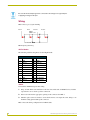
Wiring
FIG. 4 shows typical joystick wiring:
Tilt 4
Pan 2
Pan 2
Tilt 4
Zoom 6
Zoom 6
Focus 8
Focus 8
GND 17,18
GND
17, 18
+5+5V
VDC
DCREF
REF19,20
19,20
FIG. 4 Typical joystick wiring
20-Pin Header
The following table lists the pinouts for the 20-pin header:
20-Pin Header - Pinout Information
Pin
Function
Pin
Function
1
GND
11
GND
2
INPUT 1
12
INPUT 6
3
GND
13
GND
4
INPUT 2
14
INPUT 7
5
GND
15
GND
6
INPUT 3
16
INPUT 8
7
GND
17
GND
8
INPUT 4
18
GND
9
GND
19
+5 VDC REF
10
INPUT 5
20
+5 VDC REF
AXlink
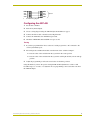
To install the AXlink data/power bus wiring:
1. Strip .25 inch off the wire insulation for all four wires. If the wire is 20 AWG or less, fold the
exposed wire over to obtain a positive connection.
2. Insert each wire into the appropriate opening on the connector. See FIG. 4.
3. Turn the captive screws clockwise to secure the fit. Do not over torque the screw; doing so can
bend the seating pin and damage the connector.
FIG. 5 shows the wiring configuration for AXlink cables.
4
AXP-AI8 Eight-Channel Analog Interface Board
Installation
PWR
PWR
AXP
AXP
AXM
AXM
GND
GND
PWR
PWR
AXP
AXP
AXM
AXM
SYSTEM
System
GND
GND
FIG. 5 AXlink wiring diagram
Configuring the AXP-AI8
1. Set the device number.
2. Turn off any unused inputs.
3. Create a wiring diagram using the AXP-AI8 System Worksheet on page 7.
4. Connect the ribbon cable or the PC board to 20-pin header.
5. Connect the AXP-AI8 to the AXlink data/power bus.
6. Check the AXlink LED. It should blink once per second.
Testing
1. If you have programmed the Axcess software, load the program into a PC connected to the
control system Master port.
2. Select Diagnostics and Watch Variable; enter the name of the variable for Input 1.
Note the value of the variable when the joystick is in the center position.
Note the value of the variable when the joystick is at full right and left (or down and up)
position.
3. Adjust the programming to reflect the actual values for the three positions.
Using this method, you have the option of using the HI and LO adjustments to achieve a full
0-5 VDC range, 2.5 V center, or to adjust the Axcess programming to the actual values sent from
the AXP-AI8 inputs.
AXP-AI8 Eight-Channel Analog Interface Board
5
Installation
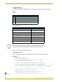
Programming
This section covers programming information and examples for the AXP-AI8 Analog Interface
Board.
Levels
Levels
Level Function
1
Voltage output channel 1 and joystick/slider control (0 - 255).
5
Voltage input channel 1 (0 - 255).
2
Voltage output channel 2 and joystick/slider control (0 - 255).
6
Voltage input channel 2 (0 - 255).
Send_Commands
Send_Commands
SEND COMMAND AI8,"'DELTA5'"
Puts channel 5 in delta mode.
SEND COMMAND AI8,"'DELTA6'"
Puts channel 6 in delta mode.
SEND COMMAND AI8,"'DELTA7'"
Puts channel 7 in delta mode.
SEND COMMAND AI8,"'DELTA5 ON'"
Puts channel 5 in delta mode.
SEND COMMAND AI8,"'DELTA6 ON'"
Puts channel 6 in delta mode.
SEND COMMAND AI8,"'DELTA7 ON'"
Puts channel 7 in delta mode.
SEND COMMAND AI8,"'DELTA5 OFF'" Takes channel 5 out of delta mode.
SEND COMMAND AI8,"'DELTA6 OFF'" Takes channel 6 out of delta mode.
SEND COMMAND AI8,"'DELTA7 OFF'" Takes channel 7 out of delta mode.
Delta mode should be used with continuous rotation potentiometers. It effectively
filters out the dead zones and provides for smooth, uninterrupted readings.
Inputs are controlled as Channels 1 through 8.
Sample Application
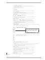
This is an example of Axcess programming that is required before using an AXP-AI8.
Example 1:
PROGRAM_NAME='AI8_EX rev 1'
(* DATE:06/18/02 TIME:17:32:26 *)
(* Date: 12/18/2001 Time: 11:50:50 AM AXedit user: JSHMOE *)
(*{{PS_SOURCE_INFO(PROGRAM STATS) *)
(**
(**
(**
(**
FIRST,
but we
use of
master
the program under studio can be written many ways
have to stay within the boundaries of the compiler and
KEYWORDS. This file was created for an AXCESS system
and when compiling in AXCESSX, the word BUTTON is NOT a KEYWORD
**)
**)
**)
**)
(***********************************************************)
(* FILE CREATED ON: 06/09/2000 AT: 13:56:05 *)
(***********************************************************)
(* FILE_LAST_MODIFIED_ON: 04/25/2001 AT: 16:59:10 *)
(***********************************************************)
Continued
6
AXP-AI8 Eight-Channel Analog Interface Board
Installation
(* ORPHAN_FILE_PLATFORM: 1 *)
(***********************************************************)
(*!!FILE REVISION: Rev 0 *)
(* REVISION DATE: 04/24/2001 *)
(* *)
(* COMMENTS: *)
(* *)
(***********************************************************)
(*}}PS_SOURCE_INFO *)
(***********************************************************)
(* DEVICE NUMBER DEFINITIONS GO BELOW *)
(***********************************************************)
DEFINE_DEVICE
AI8 = 64 (* EIGHT INPUT ANALOG BOARD *)
TP = 128 (* TOUCH PANEL *)
(***********************************************************)
(* CONSTANT DEFINITIONS GO BELOW *)
(***********************************************************)
DEFINE_CONSTANT
xBUTTON = 101 (* CHANNEL NUMBER FOR TOUCH PANEL BUTTON *)
//BUTTON = 101 (* CHANNEL NUMBER FOR TOUCH PANEL BUTTON *)
(***********************************************************)
(* VARIABLE DEFINITIONS GO BELOW *)
(***********************************************************)
DEFINE_VARIABLE
(* If you create a variable array then you have to call one of these array
elements below *)
(* Or setup the variables without an array *)
(*
IN1[2] (* VARIABLES IN WHICH TO STORE *)
IN2[2] (* ANALOG INPUT VALUES (LEVELS) *)
IN3[2]
Each variable needs two bytes to hold the
IN4[2]
IN5[2]
input value which is why the form [2]
IN6[2]
is used.
IN7[2]
IN8[2]
*)
IN1// (* VARIABLES IN WHICH TO STORE *)
IN2
(* ANALOG INPUT VALUES (LEVELS)*)
IN3
IN4
IN5
IN6
IN7
IN8
Continued
(*Each variable needs two bytes to hold the
input value which is why the form [2]
is used.*)
(** Each element of the array in this case will hold the Integer value **)
(***********************************************************)
(* LATCHING DEFINITIONS GO BELOW *)
(***********************************************************)
DEFINE_LATCHING
(***********************************************************)
(* MUTUALLY EXCLUSIVE DEFINITIONS GO BELOW *)
(***********************************************************)
DEFINE_MUTUALLY_EXCLUSIVE
(***********************************************************)
(* STARTUP CODE GOES BELOW *)
(***********************************************************)
DEFINE_START
CREATE_LEVEL AI8,1,IN1
(* HERE WE ASSOCIATE EACH AI8 *)
AXP-AI8 Eight-Channel Analog Interface Board
7
Installation
CREATE_LEVEL AI8,2,IN2
(* INPUT WITH A VARIABLE NAME *)
CREATE_LEVEL AI8,3,IN3
(* IN WHICH TO STORE THE INPUT *)
CREATE_LEVEL AI8,4,IN4
(* ANALOG VALUE (LEVEL)
*)
CREATE_LEVEL AI8,5,IN5
CREATE_LEVEL AI8,6,IN6
CREATE_LEVEL AI8,7,IN7
CREATE_LEVEL AI8,8,IN8
(*
CREATE_LEVEL AI8,1,IN1[1] (* HERE WE ASSOCIATE EACH AI8 *)
CREATE_LEVEL AI8,2,IN2[1] (* INPUT WITH A VARIABLE NAME *)
CREATE_LEVEL AI8,3,IN3[1] (* IN WHICH TO STORE THE INPUT *)
CREATE_LEVEL AI8,4,IN4[1] (* ANALOG VALUE (LEVEL)
*)
CREATE_LEVEL AI8,5,IN5[1]
CREATE_LEVEL AI8,6,IN6[1]
CREATE_LEVEL AI8,7,IN7[1]
CREATE_LEVEL AI8,8,IN8[1]
*)
(***********************************************************)
(* THE ACTUAL PROGRAM GOES BELOW *)
(***********************************************************)
DEFINE_PROGRAM
//IF(IN1[1] < 51) (* THE LEVELS FROM THE AI8 RANGE FROM *)
IF(IN1 < 51)
(* THE LEVELS FROM THE AI8 RANGE FROM *)
{ (* 0 - 1023 *)
// ON[TP,BUTTON]
// ON[TP,101]
ON[TP,xBUTTON]
}
//IF(IN5[1] = 795)
IF(IN5 = 795)
{
OFF[TP,xBUTTON]
// OFF[TP,BUTTON]
//OFF[TP,101]
}
(***********************************************************)
(* END OF PROGRAM *)
(* DO NOT PUT ANY CODE BELOW THIS COMMENT *)
(***********************************************************)
Each variable needs two bytes to hold the input value which is why the form [2] is
used (ex: [2] makes it a two-byte variable).
For additional information, refer to the Axcess Programming Language instruction manual.
8
AXP-AI8 Eight-Channel Analog Interface Board
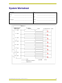
System Worksheet
System Worksheet
Dealer ID #:
Dealer:
_______________________________________ Date:
_____________________________________________
________________________________________ PO#:
__________________________________________
Job: ______________________________________________
SO#: _____________________________________________
Description: ________________________________________ Serial #: ___________________________________________
Rev# : ____________________________________________
Device #
20-Pin Header
1
2
3
4
2
Input
4
Input
6
Input
8
Input
10
Input
12
Input
14
Input
16
Input
Function
Color
+5 V DC Reference Pin 20
5
6
7
8
Input
Input GND
Pin 18
DC Reference Common
GND Common
AXP-AI8 Eight-Channel Analog Interface Board
9
brussels • dallas • los angeles • mexico city • philadelphia • shanghai • singapore • tampa • toronto* • york
3000 research drive, richardson, TX 75082 USA • 469.624.8000 • 800.222.0193 • fax 469.624.7153 • technical support 800.932.6993
038-004-1034 12/03 ©2003 AMX Corporation. All rights reserved. AMX, the AMX logo, the building icon, the home icon, and the light bulb icon are all trademarks of AMX Corporation.
AMX reserves the right to alter specifications without notice at any time. *In Canada doing business as Panja Inc.
AMX reserves the right to alter specifications without notice at any time.