1
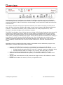
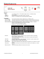
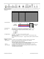
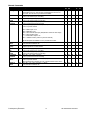
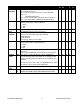
Product Manual Ethernet Head-End Controller Version 3.3 June 27, 2007 4355 Excel Pkwy, Suite 600, Addison, TX, 75001 Phone:972-931-2728 • Toll-Free: 888-972-2728 • Fax: 972-931-2765 E-Mail: [email protected] • Website: www.crwww.com Overview ............................................................................................................................................. 3 Specifications ...................................................................................................................................... 4 Physical ................................................................................................................................................... 4 Front Panel .............................................................................................................................................. 4 Control Connections .................................................................................................................................. 5 iCC-Net Connections ................................................................................................................................. 5 iCW-Net Connections ................................................................................................................................ 6 Power Connections ................................................................................................................................... 6 Includes ................................................................................................................................................... 6 Installation ......................................................................................................................................... 7 Installation ......................................................................................................................................... 7 Remote Control Connection ....................................................................................................................... 7 RF Coax and iCC-Net Operation ................................................................................................................. 7 AC Power and Net LED operation............................................................................................................... 7 I/O Port Connection .................................................................................................................................. 7 Ethernet Setup .................................................................................................................................... 8 Ethernet Connection ................................................................................................................................. 8 Reset IP Address ...................................................................................................................................... 8 RS-232 and Telnet Terminal Communication..................................................................................... 8 Connecting to ICE-HE Web Server ............................................................................................................. 9 View or Change Ethernet Settings Via the ICE-HE Web Server ..................................................................... 9 RS-232/Telnet Terminal Commands................................................................................................. 10 RS-232 Control Protocol ................................................................................................................... 12 Overview ................................................................................................................................................12 Command String Structure .......................................................................................................................12 Command format ....................................................................................................................................12 RS-232 HE Commands ...................................................................................................................... 13 RS-232 Controller Commands ........................................................................................................... 14 General Commands .................................................................................................................................14 Audio Commands ....................................................................................................................................15 Channel Commands .................................................................................................................................16 Tuning Commands...................................................................................................................................17 On-Screen Text Commands ......................................................................................................................18 RS-232 Response .............................................................................................................................. 19 Response String Structure ........................................................................................................................19 Command format ....................................................................................................................................19 RS-232 HE Response......................................................................................................................... 20 RS-232 Device Response .................................................................................................................. 21 iC-Net SmartZones ............................................................................................................................ 22 System Map....................................................................................................................................... 23 Typical RF and ICC-Net Signal Flow .................................................................................................. 24 Safety Instructions ........................................................................................................................... 25 Limited Warranty and Disclaimer ..................................................................................................... 26 RF Channel Frequencies .................................................................................................................... 27 Contemporary Research 2 ICE-HE Ethernet Head End Contemporary Research introduces a new solution for intelligent television control and distributed media management, the ICE-HE Ethernet Head-End. Through a single Ethernet port, the ICE-HE can network thousands of iC-Net TV controllers, communicating over the same CATV cable that carries the media channels. The industry-standard iC-Net protocol operates seamlessly over Ethernet networks, RS-232 control ports, RF coax, Cat5 wiring, and fiber optic cables. Custom control systems, ABC-Net Media Retrieval systems, iC Commander 4 software, and iC ToolKit software can easily integrate all TVs, video projectors, and plasma displays across a facility or campus. The ICE-HE can distribute 2-way iCC-Net data over existing CATV RF cable. Employing clear-channel RF frequencies to transmit and receive data, the iCC-Net network is compatible with any CATV system without conflict with existing channels. The bi-directional network operates over a standard low-split cable system, simplifying installation and support. Control data can also be transmitted over Category 5 and Category 3 wiring, using the ICE-HE iCW-Net ports. Three iCW-Net ports are included, each capable of connecting thousands of ICW-Net format controllers over wiring runs of up to 3,300 feet (1 Km). In addition, iCW-Net data can be sent to remote locations over fiber and videoconferencing codecs. Applications include educational television systems, presentation rooms, auditoriums, pay-per-view, theme parks, museums and industrial video networks. Connects to TCP/IP Ethernet network via 10/100baseT port using a static IP address Networks with up to 4,000 TVs through wired iCW-Net and broadband CATV iCC-Net networks o iCC-Net operates through same CATV coax as TV channels, requires no additional wiring o iCW-Net distributes data over Category 5 or 3 wiring, fiber optic cable, or codecs Sends commands to individual devices, zones, or all units from a single RS-232 port Interacts with CR ABC Media Retrieval Systems, iC Commander software, or custom control systems Includes local control buttons and I/O ports that can trigger events in PC software or control systems Provides LED feedback for network, control, and operation status Contemporary Research 3 ICE-HE Ethernet Head End Physical Size: Weight: Enclosure: Mounting: 19" [483mm] wide x 1.75" [38mm] height (1RU) x 9" [229mm] deep 3 lbs [1.36kg] All aluminum with durable black powder coat paint Shelf or 19‖ equipment rack (mounting brackets included) Front Panel RF Out Adjust: Trims iCC-Net channel output, shipped set to +55 dBmV (max) RS-232 TX LED: Yellow LED, lights when receiving RS-232 data on Remote Control RS-232 port RS-232 TX LED: Yellow LED, lights when receiving RS-232 data on Remote Control RS-232 port RS-232 DIP Switch: Sets RS-232 baud rate (9600 - 38.4K), 8 data bits, no parity, 1 stop bit Switch 1 selects high/low sensitivity for RF In signal Switch 2 resets HE IP settings to default Switches 6, 7, and 8 set RS-232 baud rate DIP 1 2 3 4 5 6 7 8 Net LED: COM LED: Error LED: Reset/Default: Emergency: Ethernet RX/TX: Off RF In Low* * On RF In High Reset IP Baud Baud Baud Baud 38,400 19,200* 9,600 4,800 2,400 1,200 6 ON OFF ON OFF ON OFF 7 ON ON OFF OFF ON ON 8 ON ON ON ON OFF OFF *Default setting Green LED for iC-Net bus, flashes once per second if network is operating, device numbers expected agree The LED will flash twice per second if the number of present and expected devices do not agree Yellow LED blinks when a valid command is received or system response sent through the Remote Control RS-232 port Red LED indicates a problem within the unit White button sends press and release RS-232 response to PC software or control system Red button sends press and release RS-232 response to PC software or control system Yellow LEDs indicate Ethernet data send and receive Contemporary Research 4 ICE-HE Ethernet Head End Control Connections Ethernet: 10/100baseT RJ-45 jack, RCX/TX LEDs indicate Ethernet data send and receive Control RS-232: Left LED Right LED Indication Off Off Off Off Off Solid Amber Blinking Amber Solid Green Blinking Green Off Solid Amber Blinking Amber Solid Green Blinking Green Off Off Off Off No link 100BASE-T Half Duplex link 100BASE-T Half Duplex link, activity 100BASE-T Full Duplex link 100BASE-T Full Duplex link, activity 10BASE-T Half Duplex link 10BASE-T Half Duplex link, activity 10BASE-T Full Duplex link 10BASE-T Full Duplex link, activity DB9 female, RS-232 data link to control system or PC RS-232 Control Port iC-Net RS-232: I/O 1 & 2: I/O Applications: 5 GND GND 5 2 RXD TXD 3 3 TXD RXD 2 9-pin D-sub female DB9 female, RS-232 data link to send iCW-Net over fiber or codec 4-pin captive screw terminal for Input/Outputs 1 and 2 2 switch closures or inputs, max 50 mA, 24 VDC, switch to GND 1 – +12 VDC 2 – Output 2 3 – Output 1 4 – GND DC power – close pins 1 & 3 to provide DC on/off Dry closure 2 – close pins 3 & 4 for dry contact to external power relay, AMX PC1 or similar Sense closure (3 & 4) on Input 1 – trigger control system to power off for all rooms iCC-Net Connections RF In: ‗F‘, female, 75 ohm impedance, RF and iCC-Net from CATV system Data Receive: Carried over the same RF coax connection as TV channels Return signal from system controllers Sub-band, 5.6MHz, narrow-band signal below standard sub-band channels -15 to +35 dBmV signal level (0 to +15 dBmV nominal) RF Out: F‘, female, 75 ohm impedance, RF to CATV distribution to controllers Data Transmit: Mid-band VHF, 74.7 MHz, narrow-band signal between channels 4 and 5 ± 80 KHz max carrier deviation +55 dBmV maximum (default) Contemporary Research 5 ICE-HE Ethernet Head End iCW-Net Connections iCW-Net 2, 3 RJ-45 female 8 pin Telco jack, supports 3300 ft [1 km] of wire RS-422/485 type data requiring at least 2 twisted wire pairs with shield or fifth conductor iCW-Net 1: 6-pin captive-screw terminal for system wiring or use with RS-422/485-format fiber or codecs iC-Net Expand RJ-11 female 6-pin Telco jack Recommended Wire: CAT5/CAT3 compatible unshielded, max 3,300 feet [1 Km] from Head End Power Connections Power In: 2.1mm coaxial jack (inside center conductor positive), 11 to 18 VDC, 12 VDC typical, 300 mA maximum (may be unregulated) UL/CSA listed wall power supply (included for domestic 110 VAC/60 Hz shipments only) Includes 10 dB RF attenuator 12 VDC Power Supply Contemporary Research 6 ICE-HE Ethernet Head End Remote Control Connection 1. Attach appropriate RS-232 cable to Remote Control RS-232 port. See page 4 for RS-232 cable wiring diagram. 2. Set desired baud rate on front-panel DIP switch. Default setting is 19.2K baud – see page 4 for DIP switch setting information. 3. Alternatively, connect via Ethernet, setup instructions on the next page. RF Coax and iCC-Net Operation 1. Connect an RF coax feed from RF Out to the system‘s RF combiner, mixing the iCC-Net Out signal with the other CATV channels. The iCC-Net Out channel operates at 74.7 MHz, in between cable channels 4 and 5. 2. In most applications, the installer will connect the included 10 dB attenuator in between, trimming the He‘s standard 55 dB output to 45 dB. 3. Using an RF signal level meter, use the front panel RF Out adjustment counterclockwise to match the RF Out signal to the other CATV sources. Limit RF Out adjustment to -10 dB, using attenuators to achieve a lower signal strength. 4. Add a Sub-CATV Diplexer after the CATV amplifier. 5. Connect the Sub-Channel output of the Diplexer to the HE RF In connection. AC Power and Net LED operation 1. Insert DC power supply plug into the Power In jack. 2. Plug power adaptor into AC wall outlet, the front-panel LEDs should turn on momentarily. 3. If iC-Net communication is functioning, the Net LED will flash once per second, or twice per second (the double-flash, indicating a difference between present and expected device, would be typical in the initial phase of the installation.) 4. Using a terminal emulator, send an AR command (p9) a few times to measure the level of background RF compared to the current Sensitivity setting (DIP switch 1, p4). 5. Set one iC-Net controller to constantly transmit using iC ToolKit. Send the AR command again the measure the level at Constant Transmit. 6. The Sensitivity level should be set in-between the background RF and constant transmit levels. I/O Port Connection 1. A simple contact closure can be wired to I/O 1 or 2, a press or release can trigger events in the PC or control system software. 2. In other applications, the I/O ports can act as closure outputs, activating an external power relay, 2x1 video switcher or other device. 3. You‘ll have to choose application – the ports act as either an output or input, not both. See Control Connections on page 5 for wiring and rating information. Contemporary Research 7 ICE-HE Ethernet Head End Ethernet Connection The ICE-HE typically communicates over a network using a static IP address, and is shipped set to a default address: IP Address: 192.168.1.251 Subnet Mask: 255.255.255.0 Gateway Address: 000.000.000.000 Odds are, at least the IP address will change when the ICE-HE is connected to the client‘s network. One your first steps will be to obtain a static address from the client‘s IT department, as well as an external gateway IP address if you intend on supporting the system from your office or anywhere outside the site‘s firewall. Once you change the settings, create a label noting the settings and attach to the back of the ICE-HE. Reset IP Address If you change the default address and forget what it is later on, you can always reset the ICE-HE back to the default settings using the unit‘s front-panel DIP switch 2. While the power is on, flip the switch off, then back on to reset the IP address. The IP and Subnet Mask will change, the Gateway will stay at its current setting. Since its possible another network device is using the default IP address, the best approach is to enter the new settings offline, outside the network. You can use one of two, requiring one of two offline options: 1. Direct PC Connection. Use an Ethernet ―Crossover‖ cable to make a direct connection to the ICE-HE Ethernet port and your PC. Two pairs of wires are reversed at one end to create a direct send/receive path for data. 2. Hub or Switch Connection. Another approach for connection is to use a standard Ethernet hub or switch between your computer and the ICE-HE. Using standard Cat5 Ethernet cables, connect your PC to one port, then connect the ICE-HE to the second port. RS-232 and Telnet Terminal Communication You can communicate with the ICE-HE with HyperTerminal using an RS-232 or TCP/IP connection to Port 2728. This can be a more flexible tool than the Web Server, because you can view and change IP address information, as well as cross-check iC-Net devices and RF receive levels. Contemporary Research 8 ICE-HE Ethernet Head End Connecting to ICE-HE Web Server Once you‘ve established an Ethernet connection to the ICE-HE, enter http://192.168.1.251 to connect to the unit‘s onboard Web server. You should see the ICE-HE home page in your browser. Your PC‘s IP address must be in the same group as the ICE-HE. For example, when the HE is set to 192.168.1.251, your IP address must be set to 192.168.1.x. View or Change Ethernet Settings Via the ICE-HE Web Server 1. When you see the ICE-HE home page, click on the ICE-HE IP Setup Tool link to see the ICE-HE Connect page: 2. To change the IP settings, click on the Change Settings button on the left. 3. 4. 5. 6. Enter new settings Mark new settings before saving There is a setting for password protection, but that feature is not presently implemented Click on Update Settings to enter new settings Contemporary Research 9 ICE-HE Ethernet Head End Employ standard Windows Terminal program, set to baud rate match DIP switch setting on front of HE. Command Description Commands shown in ASCII and end with carriage return (Decimal 13, Hex $0D, or Enter key). Response displays * character to signify end of characters, or time out if no characters are received after 2 seconds. Echo Enable EN Tip: Just hit Enter to repeat any Terminal command, ESC to clear or cancel current command Enables character echo so you can see typed characters on screen. Echo Disable EF Disables terminal character display (default). Version Reset VE ID IB Z! Displays HE software version Displays HE software version Displays HE boot loader software version Performs system reset. Show Devices SD Show Missing SM Displays list of 2-way devices stored in HE memory. List can be created by iC Commander software, ABC-MRC software, or Scan and Build command below. Example Response: Devs Present: 257-261 263 265-271* Displays list of missing 2-way devices (compared to HE memory list). Example Response: Devs Missing: 262 -263 264* Displays number of present devices and number of devices expected. Example Response: Num Devs Present : 1 Num Devs Expected : 53* Displays number of present devices and number of devices expected. Example Response: SN 0001/0053* Show Present SP Show Numbers SN Scan and Show SZ Scans iC-Net and displays list of all 2-way devices found (does not change HE memory). Scan and Build Z^ Scans iC-Net and saves list of all 2-way devices found into HE memory. Show Log L Clear Log DL Returns four hex bytes, separated by commas. If any of the bytes change as you repeat the command, there is likely an error in return communication from iC-Net devices. Clears the L hex bytes to zero. RF Receive Level AR Level RF Received (idle) background level, no units constantly transmitting Example Responses: AR RRRR/SSSS = Receive/Sensitivity levels AR 0321/1337 = 0.321V “quiet” receive level, 1.337V high threshold AR 0321/0693 = 0.321V “quiet” receive level, 0.693V low threshold AR 2250/0693 = 2.251V constant transmit receive level, 0.693V low threshold RF Output AO This command is used to check RF levels at 5.6MHz, compared to the current sensitivity level setting (DIP Switch 1, page 4). Test the RF receive level a few times when the iC-Net units are not transmitting, then again when one iC-Net unit is set to constantly transmit. The Sensitivity level should fall about halfway between quiet and constant transmit RF levels. Displays RF output level DIP Setting AS Example Response: AO 5000* (Full Output) Displays DIP switch setting in binary format Example Response: AS 222* (Switches 1 and 6 off) Contemporary Research 10 ICE-HE Ethernet Head End Command IP Address Description IP IP returns the current MAC address, Ethernet firmware version, current IP address, subnet mask, and gateway. Response example (S or D at end of IP signifies DHCP or Static address): MAC address 00204A80E637 Lan Software version 01.6 (040308) XPTE $IP=192.168.001.251S IG=000.000.000.000 IM=255.255.255.000 IG Gateway IG IM Subnet IM Contemporary Research IP = xxx.xxx.xxx.xxx Defines IP address, then sends status (0.0.0.0 = DHCP) IG = Returns current MAC address, Ethernet firmware version, current IP information IG = xxx.xxx.xxx.xxx Defines IP gateway, then sends status IM = Returns current MAC address, Ethernet firmware version, current IP information IM = xxx.xxx.xxx.xxx Defines IP subnet mask, then sends status 11 ICE-HE Ethernet Head End Overview RS-232 control for up to 4000 iC-Net devices is provided through an iC series Head-End Network Controller. The ICC-HE Head-End manages iC-Net communication over RF Coax to ICC-series devices as well as ICW-series devices over twisted-pair Cat3/5 wiring. The ICW-HE Head-End operates on the Cat5 network only. Each device is assigned a unique device number from 1 to 4000 to which control commands are addressed. The devices are organized into 16 zones of 255 devices. All the devices in each zone will respond to a single ―virtual device number‖ — one device number that represents all devices in each zone. There is also a global device number, 4095, that will command all devices in the system. This feature dramatically speeds up system operation and programming, because one command can affect an entire group of devices—or all. To take advantages of this feature, review the section iC-Net Zones in this manual. In ABC-Net Media Retrieval Systems, we reserve the first group of devices, 1-255, for components operating on a connected control system. Zones 1-16 are used for CR TV Controllers, Video Display Controllers and Tuners. As it‘s unlikely any system will use all 4000 devices, this may be a good device standard for your system as well. The Remote RS-232 port on the Head-End Network Controller can communicate from 1200 to 38.4K baud. The factory default setting is 19.2K baud, 8 data bits, No parity, and 1 stop bit. Command String Structure Characters in command strings are expressed in a combination of hex and ASCII characters. Single-byte hex numbers are preceded by the „$‟ symbol ASCII characters or strings are enclosed in single quotes Numbers not marked as hex or ASCII are a single decimal byte Parameters shown in < > brackets are single byte A series of multiple commands or parameters are set apart by [ ] brackets Commas separate the bytes, but are not part of the protocol Double quotes enclose the command string, but are not part of the protocol Contemporary Research Command format “$A5,<dh>,<dl>,<ncb>,<cmd1>,<parameter> [<cmdN>]" $A5 <dh> <dl> <ncb> <cmd1> <parameter> [<cmdN>] 12 Starts the command The zone or high order byte of the device The unit or low order byte of the device (0 for global zone) The number of command bytes to follow The first command byte Command parameters (not used by all commands) Multiple commands can be concatenated, with byte count added to <ncb> ICE-HE Ethernet Head End The following commands apply to the HE only. Commands addressed to controllers are included with the Product Manual for the specific device. Command Closures Device Status Contemporary Research Y_ SP Description “$A5,0,0,3, „Y‟ <I/0 Port>‟ ” (7 bytes) Turns the two internal closures on and off. Closure 1 is typically used to control the optional buzzer, Closure 2 typically used to control an external camera power relay. “$A5,0,0,3, „Y10‟” turns Closure 1 off “$A5,0,0,3, „Y11‟” turns Closure 1 on “$A5,0,0,3, „Y20‟” turns Closure 2 off “$A5,0,0,3, „Y21‟” turns Closure 2 on "$A5,0,0,2,'SP'" (6 bytes) Queries the Head-End for the number of devices present on the network and the number of devices expected. 13 ICE-HE Ethernet Head End The following commands summarize RS-232 commands to iC-Net controllers. There is a high degree of compatibility between Contemporary Research devices; most commands execute a similar action or response in nearly all units. Refer to each unit‘s Product Manual for specific programming information. General Commands Command Description ICC IRC ICC VDC PRZ PSC ZS2 ICC1 IR Power Off PO “$A5,<dh>,<dl>,2,‟P0‟ ” (6 bytes) – checks status for true power control X 3 X X X Power On P1 “$A5,<dh>,<dl>,2,‟P1‟ ” (6 bytes) – checks status for true power control X 3 X X X Power Toggle RS-232 Control IR Control PT “$A5,<dh>,<dl>,2,‟PT‟ ” (6 bytes) – checks status for true power control X 3 X X X T0 Closures Y- “$A5,<dh>,<dl>,3,‟T0‟<type> ” (7 bytes) – Sets RS-232 control codes Identical to on-screen menu 45700 command for VDC. “$A5,<dh>,<dl>,3,‟T1‟<type> ” (7 bytes) – Sets IR device type Identical to on-screen menu 45700 command for IR-format controllers. “$A5,<dh>,<dl>,3, „Y‟ <I/0 Port>‟ ” (7 bytes) Turns the two internal closures on and off. Closure 1 is typically used to control the optional buzzer, Closure 2 typically used to control an external camera power relay. Control Lock T1 LM Control String UX Device Status SP Notes 1 2 3 “$A5,<dh>,<dl>,3, „Y10‟” turns Closure 1 off “$A5,<dh>,<dl>,3, „Y11‟” turns Closure 1 on “$A5,<dh>,<dl>,3, „Y20‟” turns Closure 2 off “$A5,<dh>,<dl>,3, „Y21‟” turns Closure 2 on “$A5,<dh>,<dl>,3,'LM',<control>” (7 bytes) Locks out front panel and IR remote control functions. Bit 7 Selects IR remote control operation (0=enabled, 1=disabled) Bit 6 Selects volume control operation (0=enabled, 1=disabled) Bit 5 - 1 Always 0 Bit 0 Selects front panel button operation (0=enabled, 1=disabled) "$A5,<dh>,<dl>,2+string length>,'UX'<string>" (variable bytes) Sends an RS-232 string (ASCII, decimal, or hex) directly to the TV display. Ex: "$A5,1,2,6,'UX, 'PON', 13" Sends PON, followed by carriage return (device 258) "$A5,0,0,2,'SP'" (6 bytes) Queries the Head-End for the number of devices present on the network and the number of devices expected. 1-way units do not respond to command Zenith LM Bit 7 affects both IR control and front panel lockout VDC sends discrete power on and power off commands Contemporary Research 14 X X X X X X X X X X 2 1 1 X X X ICE-HE Ethernet Head End Audio Commands Command Description Volume VL Ramp Up VU Ramp Down VD Stop Ramp VV Mute On VM Mute Off VX Toggle Mute VT Save Level VW Power-up Volume S5 Mono/Stereo S7* Bass Gain S8* Treble Gain S9* Notes * “$A5,<dh>,<dl>,3,‟VL‟,<vol level>” (7 bytes) Sets volume level 0 = Mute 1 – 63 = Minimum level (1) to maximum volume (63) “$A5,<dh>,<dl>,2,‟VU‟ ” (6 bytes) Starts volume ramping up “$A5,<dh>,<dl>,2,‟VD‟ ” (6 bytes) Starts volume ramping up “$A5,<dh>,<dl>,2,‟VV‟ ” (6 bytes) Stop volume ramp “$A5,<dh>,<dl>,2,‟VM‟ ” (6 bytes) Mutes volume “$A5,<dh>,<dl>,2,‟VX‟ ” (6 bytes) Unmutes volume “$A5,<dh>,<dl>,2,‟VT‟ ” (6 bytes) Toggles between mute on and off “$A5,<dh>,<dl>,2,‟VW‟ ” (6 bytes) Save current volume level, default when unit powers up To power-up to last level, set volume to zero (VL) and save. "$A5,<dh>,<dl>,3,'S5',<volume>" (7 bytes) Sets volume level when unit powers up 0 = restore to previous level 1 – 63 = Set from minimum (1) to maximum level (63) “$A5,<dh>,<dl>,3,‟S7‟, <mode>” (7 bytes) 0=mono, 1=stereo “$A5,<dh>,<dl>,3,‟S8‟, <mode>” (7 bytes) Sets bass gain “$A5,<dh>,<dl>,3,‟S9‟, <mode>” (7 bytes) Sets treble gain Reserved for future stereo iC-Net products Contemporary Research 15 ICC IRC ICC VDC PRZ PSC ZS2 ICC1 IR X X X X X X X X X X X X X X X X X X X X X ICE-HE Ethernet Head End Channel Commands Command Description Ts & Qs The following T-series channel commands select a channel and display the channel label on the TV, while Q-series commands don‟t show the onscreen text. ICC1-IR does not provide channel labels. “$A5,<dh>,<dl>,2,‟TU‟ ” (6 bytes) Tunes to next channel up in Tune Ring “$A5,<dh>,<dl>,2,‟TD‟ ” (6 bytes) Tunes to next channel down in Tune Ring “$A5,<dh>,<dl>,2,‟TP‟ ” (6 bytes) Tunes to previous channel in Tune Ring “$A5,<dh>,<dl>,3,‟TC‟, <channel>” (7 bytes) Tunes to a specific channel T Channel Up TU T Channel TD Down T Channel TP Previous Force T Chan TC 124 = 125 = 126 = 127 = 0= 255 = Select T Chan Channel Query Q Channel Up Q Channel Down Q Channel Previous Force Q Chan TT Select Q Chan QT T? QU QD QP QC ICC ICC IRC VDC PSC ZS2 ICC1 IR X X X X X X X X X X X X X X X X X X X X X X X X X X X X X X X X X X X X X X X X X X X X X X X X X X X X RGB 2 input on TV RGB input on TV Select external A/V input (IRC/VDC also selects TV video input) Select S-Video Input Blank video output to TV Unblank TV video (restore to previous channel) Tip: Not all inputs are available on every TV make and model. “$A5,<dh>,<dl>,2,‟QT‟,<channel>” (7 bytes) Tunes channel if included in TR “$A5,<dh>,<dl>,2,‟T?‟ ” (6 bytes) Request response for current channel “$A5,<dh>,<dl>,2,‟QU‟ ” (6 bytes) Tunes to next channel up in Tune Ring “$A5,<dh>,<dl>,2,‟QD‟ ” (6 bytes) Tunes to next channel down in Tune Ring “$A5,<dh>,<dl>,2,‟QP‟ ” (6 bytes) Tunes to previous channel in Tune Ring “$A5,<dh>,<dl>,3,‟QC‟, <channel>” (7 bytes) Tunes to a specific channel Same special-function channels as in the T Channel Select section above “$A5,<dh>,<dl>,2,‟QT‟,<channel>” (7 bytes) Tunes channel if included in TR Contemporary Research PRZ 16 ICE-HE Ethernet Head End Tuning Commands Command Description Operating Parameters TM Tuner Mode SO Marquee Chan Video Loss Detection T2 Tuner Mode SO Tune Ring TR Channel Labels TN Display Label Notes Q2 “$A5,<dh>,<dl>,3,‟TM‟,<setting>” (7 bytes) Sets up key functions in the unit bit 7 = Selects TV frequency tuning mode, 0=CATV,1=Broadcast bit 6 – 3 = 0 bit 2 = Channel up/down operation, 0=Tune Ring, 1=Send IR Keypad response bit 1 = Numeric channel labels, 0=num labels off, 1=num labels on) bit 0 = Alpha channel labels, 0=alpha labels off, 1=alpha labels on "$A5,<dh>,<dl>,3,'S0',<tune mode>" (7 bytes) Sets tuner mode to CATV or Broadcast/Antenna 0 = CATV 1 = Broadcast/Antenna 2 = HRC 3 = IRC “$A5,<dh>,<dl>,3,‟T2‟<channel> ” (7 bytes) Sets default channel selected when unit powers up "$A5,<dh>,<dl>,3,'Q2',<video loss mode>" (7 bytes) Selects response when a loss of video signal is detected 0=Both audio and video muted (default-blue screen for video) 1=Audio muted only 2=Video muted only 3=No muting (do nothing on loss of video) "$A5,<dh>,<dl>,3,'S0',<tune mode>" (7 bytes) Sets tuner mode to CATV or Broadcast/Antenna 0 = CATV 1 = Broadcast/Antenna 2 = HRC 3 = IRC Ex3: “$A5,<dh>,<dl>,9,‟TR‟, $82,5,7,$89,13” sets channels 2-5, 7, and 9-13. You can specify a range using MSB bit for the first channel; the next byte is the last. “$A5,<dh>,<dl>,<ncb>,„TN‟,<channel>,<label>” (variable bytes) Stores an ASCII string as the channel label. The text will appear briefly when the channel is selected, if the feature has been activated by TM command. TC Ex1: “$A5,<dh>,<dl>,6,„TN‟, „7‟, „PBS‟ ” unit displays PBS when 7 selected Ex2: “$A5,<dh>,<dl>,3,„TN‟, „7‟ ” Clears alpha label for channel 7 Ex3: “$A5,<dh>,<dl>,4,„TN‟,0,0” Clears all alpha labels “$A5,<dh>,<dl>,2,‟TC‟ ” (6 bytes) – Displays channel label for about 15 sec 1 4 1-way units do not send the TM K keypad responses for bit 2 IRC/VDC ignores TM Bit 7 (tuning), SO command sets tuning mode Contemporary Research 17 ICC IRC ICC VDC PRZ PSC ZS2 4 4 1 1 X X X X X X X X X X X 1 1 X X X X X X X X ICC1 IR X ICE-HE Ethernet Head End 1 On-Screen Text Commands Command Write Text Description DM “$A5,<dh>,<dl>,<ncb>,„DM‟, <start line>,<text color>,<background color>, <background>,<size and shadow>,<timeout>,<message bytes>” (variable bytes) Clears current text, displays text message over video (default) or blank background. The built-in character generator can accept up to 40 characters of text (including carriage returns), 28 characters per line. Use a hex $0D or decimal 13 in the text as a carriage return, which will advance CG to the next line, first space on the right. ICC IRC ICC VDC PRZ PSC ZS2 5 5 X X X X X X X X X X X X X X X X X X X X X X X X Start Line - 1-11 Text Color - 1-7= White Text Background Color – 0-7=Transparent (no background) Full screen background – 0=normal insert over video, 1=blue screen Size and Shadow – 0-3=small text with drop shadow Time-Out – 0=15-second display, 1=persistent Persistent text stays on screen until the next DM, or new Menu or channel. Ex1: “$A5,<dh>,<dl>,10,„DM‟, 2,7,0,0,1,0,‟TEST‟ ” displays the word TEST on the second line, white text, inserted over video, small size with drop shadow, and timing out after 15 seconds. Ex2: “$A5,<dh>,<dl>,2,„DM‟ ” clears on-screen display, also clears persistent text The IRC and VDC use white text and clear backgrounds when it receives a Text or Background Color parameter between 1 and 7, and accepts values 0-3 for text size and shadow. This allows compatibility with Smart TVs mixed in the same system that can display other colors and fonts. Advanced The following commands provide advanced CG text operation Fast Write DN “$A5,<dh>,<dl>,<ncb>,‟DN‟, <text> ” (variable bytes) Clears display, writes specified text starting at column 1, row 1. $0D and hex $EA, $EB, $DC, and $DB can be included, operate same as matching commands below. Write Here DW “$A5,<dh>,<dl>,<ncb>,‟DW‟, <text> ” (variable bytes) Writes specified text starting at present cursor position. Accepts same Hex as DN. Row, DG “$A5,<dh>,<dl>,4,‟DG‟, <row>, <column>” (8 bytes) Column Moves the cursor to the specified row and column position. If row is 0, then row will not be changed, and if column is 0, then column will not be changed. Cursor E7 “$A5,<dh>,<dl>,3,‟E7‟, <column>” (7 bytes) Column Sends cursor to specified column. Cursor Row E8 “$A5,<dh>,<dl>,3,‟E8‟, <row>” (7 bytes) Sends cursor to specified row. Return EB “$A5,<dh>,<dl>,2,‟EB‟ ” (6 bytes) Moves cursor down to the first column of the next row. Clear All EA “$A5,<dh>,<dl>,2,‟EA‟ ” (6 bytes) Clears display, sends cursor to column 1, row 1. Clear to End DC “$A5,<dh>,<dl>,2,‟DC‟ ” (6 bytes) Clear on-screen display from cursor to end of screen, position stays the same. Clear Line DB “$A5,<dh>,<dl>,2,‟DB‟ ” (6 bytes) Clear on-screen display from cursor to end of line, cursor position stays the same. Clear Spaces E9 “$A5,<dh>,<dl>,3,‟E9‟, <num spaces>” (7 bytes) Clears specified number of spaces, starting from cursor to the right. Text DQ “$A5,<dh>,<dl>,3,‟DQ‟, <time>” (7 bytes) Timeout Sets screen timeout to specified time in seconds (1-254). If time is 0 or 255, any text on the screen will persist indefinitely, or until cleared. Notes 5 IRC/VDC will respond to all formatting commands, using white text on transparent background Contemporary Research 18 ICE-HE Ethernet Head End ICC1 IR Contemporary Research 2-way iC-Net devices will send a response over the network whenever there is there is a change in status or command from an IR remote or front panel. Response String Structure Characters in response strings are expressed in a combination of hex and ASCII characters. For clarity, the following protocol examples use the following conventions: ASCII characters or strings are shown enclosed in single quotes Numbers shown that are not in single quotes are a single decimal byte Parameters shown in < > brackets are single byte A series of multiple commands or parameters are set apart by [ ] brackets Commas separate the bytes, but are not part of the protocol Double quotes enclose the command string, but are not part of the protocol Command format ― ‗<‘,<dh>,<dl>,<nrb>,<rb1>, <para1> [<rbN>]" ‗<‘ <dh> <dl> <nrb> <rb1> <para1> [<rbN>] Starts the response The zone or high order byte of the device The unit or low order byte of the device (0 for global zone) The number of response bytes to follow The first response byte Associated parameters, if any Multiple responses may be included Contemporary Research 19 ICE-HE Ethernet Head End The following responses apply to the HE only. Response Key-I/O Description K “ „<‟,0,0,2,'K',<IR Key>" (6 bytes) Sent when the Reset or Emergency buttons are pressed, or when I/O 1 or 2 receives a closure. PC software or a control system connected to the Control RS-232 port can receive the response and activate a programmed event. Device Query SP 101 = Reset button pressed 229 = Reset button released 102 = Emergency button pressed 230 = Emergency button released 103 = I/O 1 input closed 231 = I/O 1 input opened 104 = I/O 2 input closed 232 = I/O 2 input opened " '<',0,0,4,'SP',<number devices present>,<number devices expected> (8 bytes) Sent in response to HE Device Status query. Tip: If the number of present and expected devices match, the green Net LED on the HE will blink once per second. If the two numbers do not agree, the LED blinks twice per second. Contemporary Research 20 ICE-HE Ethernet Head End The following responses are common to all iC-Net 2-Way devices. Response New Channel T Description “ „<‟,<dh>,<dl>,2,'T',<new channel>" (6 bytes) IR Function R Sent in response to T? command. “ „<‟,<dh>,<dl>,2,'F',<IR Function>" (6 bytes) Sent when unit receives a new function command is pressed (1-8) or released (0) from the IR remote. IR Key K 0 = Release 1 = Play 2 = Stop 3 = Pause 4 = Fast Forward 5 = Rewind 8 = Record “ „<‟,<dh>,<dl>,2,'K',<IR Key>" (6 bytes) Sent when unit receives a new key command is pressed (10-23) or released (0) from the IR remote. 0 = Release 10 - 19 = Numeric keypad entry 0 – 9 21 = Enter 22 = Channel Up 23 = Channel Down 29 = Menu 101 = Previous Channel IR Menu M 102 105 106 107 108 109 110 = = = = = = = Timer Media Menu Cursor Right Cursor Left Cursor Up Cursor Down Media Select The 0 – 9, Channel Up/Down functions are sent only if enabled in the TM command (Bit 2 = 1). The Channel Up/Down responses will be sent if the Tune Ring contains no channels – see Ex2 in the Tune Ring command section. “ „<‟,<dh>,<dl>,5,'M',<msh>, <msl>, <mph>, <mpl>" (9 bytes) Sent when unit receives a new Menu command is pressed or released (0) from the IR remote. Menu Selection high and low bytes are in <msh> and <msl>. Menu Parameter high and low bytes are in <mph> and <mpl>. A Menu command is initiated by pressing the Menu key, followed by a numeric entry, then the Enter or Channel Up key. During the Menu process, the Channel Down key acts as a backspace or delete key. Some selections that need only a single numeric entry and will have a parameter value of zero (0). Those keys are 0, 8, 9, 18, 20, 30, 900, 911, and 912. Menu selections that will prompt the user to enter a second parameter entry are: 1 = Select Media 2 = Password 3 = Chapter Search 4 = Frame Search 11 = Channel 21 = Page Zone 22 = Page Room 25 = Go 21 = Attach Zone 32 = Attach Room Tip: The Menu entries are active even if the TV power is off. Contemporary Research 21 ICE-HE Ethernet Head End To simplify controlling groups of devices, iC-Net is divided into 16 zones of 255 devices, also called SmartZones. All the devices within each zone can be controlled simultaneously by sending a command to a single ―virtual device number‖. For example, noting the SmartZone chart below, if we send a Power On command to device #256, any TV controller numbered between 257 and 511 will instantly turn on. If we send a Power Off command to device #4095, all devices in the system will turn off. This is an immensely powerful feature, because most systems can only address one device at time. So if you need to turn off all 50 TV in a zone, you would need to send 50 commands. In addition to the hassles of creating multiple commands, there would be a long delay between the first and last command. One command, instant response is easier. ABC Media Retrieval Systems reserve Zone 0 for devices used in the central control system, 1 -15 for iC-Net devices. This structure may be useful for your application, or you could use Zone 0 just like any other iC-Net zone. Zone 1 2 3 4 5 6 7 8 9 10 11 12 13 14 15 All Zones First Device 257 513 769 1025 1281 1537 1793 2049 2305 2561 2817 3073 3329 3585 3841 Last Device 511 767 1023 1279 1535 1791 2047 2303 2559 2815 3071 3327 3583 3839 4000 Virtual Device 256 512 768 1024 1280 1536 1792 2048 2304 2560 2816 3072 3328 3584 3840 4095 Tip:You've probably figured out that you never want to assign a virtual device number to an actual device in the system. If you assigned #1536 to a device, all the TV controllers in Zone 6 would respond every time you sent a command to that one device. Contemporary Research 22 ICE-HE Ethernet Head End One of the key tasks for iC-Net integrators is to create a logical System Map, assigning device numbers to TV controllers so they fall into logical zones. The device mapping could be sorted by type or location; whichever suits the application. iC-Net Zone 1 2 3 4 Zone W 1st Floor nd W2 Room Device W151 W152 W153 W154 257 258 259 260 Floor E 1st Floor E 2nd Floor W251 W252 W253 W254 E151 E152 E153 E154 E251 E252 E253 E254 Contemporary Research 256 iC-Net Zone Zone 5 Coffee Areas 6 512 Room Device G100 G150 G151 1281 1282 1283 Day Care TV 1 TV 2 513 514 515 516 7 Hallways W1 W2 E1 E2 768 769 770 771 772 8 Office Admin A/V Center 1024 All Zones All 1280 1536 1537 1538 1792 1793 1794 1795 1796 2048 2049 2050 4095 1025 1024 1025 1026 23 ICE-HE Ethernet Head End This diagram shows the structure of a typical Contemporary Research media retrieval system. One of the key aspects for iCC-Netcommunication is to provide a forward and return (subchannel) path for data if you‘re using 2-way TV Controllers. Contemporary Research 24 ICE-HE Ethernet Head End Read before operating equipment. 1. Cleaning - Unplug this product from the wall outlet before cleaning. Do not use liquid cleaners or aerosol cleaners. Use a damp cloth for cleaning. 2. Power Sources - Use supplied or equivalent UL/CSA approved low voltage DC plug-in transformer. 3. Outdoor Antenna Grounding - If you connect an outside antenna or cable system to the product, be sure the antenna or cable system is grounded so as to provide some protection against voltage surges and built-up static charges. Section 810 of the National Electrical Code, ANSI/NFPA No. 70, provides information with respect to proper grounding of the mast and supporting structure, grounding of the lead-in wire to an antenna discharge unit, size of grounding conductors, location of antenna discharge unit, connection to grounding electrodes, and requirements for the grounding electrode. 4. Lightning - Avoid installation or reconfiguration of wiring during lightning activity. 5. Power Lines - Do not locate an outside antenna system near overhead power lines or other electric light or power circuits or where it can fall into such power lines or circuits. When installing an outside antenna system, refrain from touching such power lines or circuits, as contact with them might be fatal. 6. Overloading - Do not overload wall outlets and extension cords as this can result in a risk of fire or electric shock. 7. Object and Liquid Entry - Never push objects of any kind into this product through openings as they may touch dangerous voltage points or short out parts, resulting in a fire or electric shock. Never spill liquid of any kind on the product. 8. Servicing - Do not attempt to service this product yourself as opening or removing covers may expose you to dangerous voltage or other hazards. Refer all servicing to qualified service personnel. 9. Damage Requiring Service - Unplug this product from the wall outlet and refer servicing to qualified service personnel under the following conditions: When the power supply cord or plug is damaged. If liquid spills or objects fall into the product. If the product is exposed to rain or water. If the product does not operate normally by following the operating instructions. Adjust only those controls that are covered by the operating instructions. An improper adjustment of other controls may result in damage and will often require extensive work by a qualified technician to restore the product to its normal operation. If the video product is dropped or the cabinet is damaged. When the video product exhibits a distinct change in performance, this indicates a need for service. Note to CATV system installer: This reminder is provided to call CATV system installer's attention to Article 820-40 of the National Electrical Code (Section 54 of Canadian Electrical Code, Part I), that provides guidelines for proper grounding and, in particular, specifies that the cable ground shall be connected to the grounding system of the building as close to the point of cable entry as possible. Contemporary Research 25 ICE-HE Ethernet Head End Contemporary Research Corporation (CR) warrants this product to be free from defects in material and workmanship under normal use for a period of two years from the date of purchase from CR. Should such a defect occur CR will repair or replace, at their option, the defective product at no cost for parts or labor. This warranty extends to product purchased directly from CR or an Authorized CR Dealer. Consumers should inquire from selling dealer as to the nature and extent of the dealer's warranty, if any. All warranty claims must be shipped pre-paid to the factory. Call or fax to obtain a Return Material Authorization (RMA) number. CR is not liable for any damages caused by any of its products or for the failure of any products to perform, including any lost profits, lost savings, incidental damages, or consequential damages. CR is not responsible for any claim made by a third party or made for you by a third party. This limitation of liability applies whether damages are sought, or a claim is made, under this warranty or as a tort claim (including negligence and strict product liability), a contract claim, or any other claim. This limitation of liability cannot be waived or amended by any person. This limitation of liability will be effective even if CR or an authorized representative of CR has been advised of the possibility of any such damages. Some states do not allow a limitation of how long an implied warranty lasts. Some states do not allow the limitation or exclusion of incidental or consequential damages for consumer products. In such states, the limitation or exclusion of the Limited Warranty may not apply to you. This Limited Warranty gives you specific legal rights. You may also have other rights that may vary from state to state. You are advised to consult applicable state laws for a full determination of your rights. Except as expressly set forth in this Limited Warranty, CR makes no other warranties, expressed or implied, including any implied warranties of merchantability or fitness for a particular purpose. CR expressly disclaims all warranties not stated in this Limited Warranty. Any implied warranties that may be imposed by law are limited to the terms of this Limited Warranty. Contemporary Research 26 ICE-HE Ethernet Head End Channel CATV/IRC HRC FCC Chan T Band CATV HRC FCC High Chan CATV HRC FCC Chan CATV HRC FCC 47 361.25 360.0180 669.25 79 553.25 552.0276 861.25 iCC-Net 5.6 (In) 7 175.25 174.0087 175.25 48 367.25 366.0183 675.25 80 559.25 558.0279 867.25 T7 7.00 8 181.25 180.0090 181.25 49 373.25 372.0186 681.25 81 565.25 564.0282 873.25 T8 13.00 9 187.25 186.0093 187.25 50 379.25 378.0189 687.25 82 571.25 570.0285 879.25 T9 19.00 10 193.25 192.0096 193.25 51 385.25 384.0192 693.25 83 577.25 576.0288 885.25 T 10 25.00 11 199.25 198.0099 199.25 52 391.25 390.0195 699.25 84 583.25 582.0291 T 11 31.00 12 205.25 204.0102 205.25 53 397.25 396.0198 705.25 85 589.25 588.0294 T 12 37.00 13 211.25 210.0105 211.25 54 403.25 402.0201 711.25 86 595.25 594.0297 T 13 43.00 55 409.25 408.0204 717.25 87 601.25 600.0300 T14 49.00 Super Low 23 217.25 216.0108 525.25 56 415.25 414.0207 723.25 88 607.25 606.0303 24 223.25 222.0111 531.25 57 421.25 420.0210 729.25 89 613.25 612.0306 2 55.25 54.0027 55.25 25 229.25 228.0114 537.25 58 427.25 426.0213 735.25 90 619.25 618.0309 3 61.25 60.0030 61.25 26 235.25 234.0117 543.25 59 433.25 432.0216 741.25 91 625.25 624.0312 4 67.25 66.0033 67.25 27 241.25 240.0120 549.25 60 439.25 438.0219 747.25 92 631.25 630.0315 iCC-Net 74.7 (Out)* 72.0036* 28 247.25 246.0123 555.25 61 445.25 444.0222 753.25 93 637.25 636.0318 5 77.25/79.25 78.0039 77.25 29 253.25 252.0126 561.25 62 451.25 450.0225 759.25 94 643.25 642.0321 6 83.25/85.25 84.0042 83.25 30 259.25 258.0129 567.25 Hyper 100 649.25 648.0324 31 265.25 264.0132 573.25 63 457.25 456.0228 765.25 101 655.25 654.0327 FM 95 91.25 90.0045 91.25 32 271.25 270.0135 579.25 64 463.25 462.0231 771.25 102 661.25 660.0330 96 97.25 96.0048 97.25 33 277.25 276.0138 585.25 65 469.25 468.0234 777.25 103 667.25 666.0333 97 103.25 102.0051 103.25 34 283.25 282.0141 591.25 66 475.25 474.0237 783.25 104 673.25 672.0336 35 289.25 288.0144 597.25 67 481.25 480.0240 789.25 105 679.25 678.0339 Mid 98 109.25 108.0054 109.25 36 295.25 294.0147 603.25 68 487.25 486.0243 795.25 106 685.25 684.0342 99 115.25 114.0057 115.25 37 301.25 300.015 609.25 69 493.25 492.0246 801.25 107 691.25 690.0345 14 121.25 120.0060 471.25 38 307.25 306.0153 615.25 70 499.25 498.0249 807.25 108 697.25 696.0348 15 127.25 126.0063 477.25 39 313.25 312.0156 621.25 71 505.25 504.0252 813.25 109 703.25 702.0351 16 133.25 132.0066 483.25 40 319.25 318.0159 627.25 72 511.25 510.0255 819.25 110 709.25 708.0354 17 139.25 138.0069 489.25 41 325.25 324.0162 633.25 73 517.25 516.0258 825.25 111 715.25 714.0357 18 145.25 144.0072 495.25 42 331.25 330.0165 639.25 74 523.25 522.0261 831.25 112 721.25 720.0360 19 151.25 150.0075 501.25 43 337.25 336.0168 645.25 75 529.25 528.0264 837.25 113 727.25 726.0363 20 157.25 156.0078 507.25 44 343.25 342.0171 651.25 76 535.25 534.0267 843.25 114 733.25 732.0366 21 163.25 162.0081 513.25 45 349.25 348.0174 657.25 77 541.25 540.0270 849.25 115 739.25 738.0369 22 169.25 168.0084 519.25 46 355.25 354.0177 663.25 78 547.25 546.0273 855.25 116 745.25 744.0372 Frequencies -—The visual carrier frequency (channels T7-116) is shown in this chart, in MHz. For the aural carrier frequency, add 4.5 MHz to the visual carrier. The lower edge of the channel is 1.25 MHz below the visual carrier and the upper edge is 4.75 MHz above the visual carrier. CATV/IRC — IRC spacing is the same as standard CATV frequencies, except for Channels 5 and 6. HRC/IRC — About 10% of CATV systems use these alternate frequency plans, created to reduce ―beat‖ interference. FCC – U.S. Broadcast VHF/UHF *Channel 1 — IRC/HRC spacing created a Channel 1 between 4 and 5, the rarely used channel must be shifted to different frequency for IC-Net operation Contemporary Research 27 ICE-HE Ethernet Head End