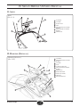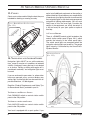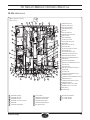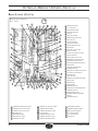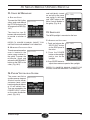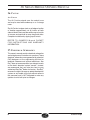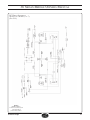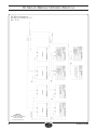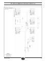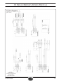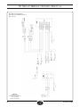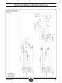
1
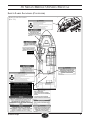
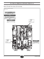
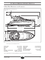
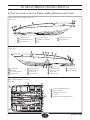
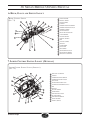
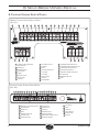
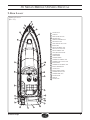
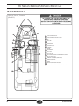
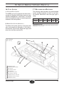
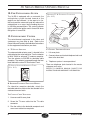
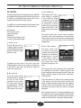
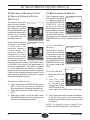
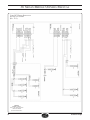
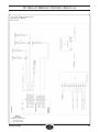
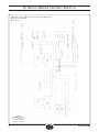
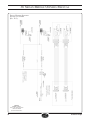
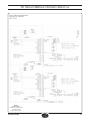
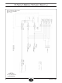
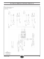
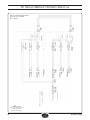
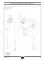
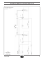
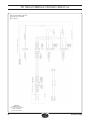
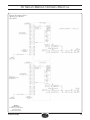
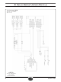
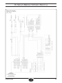
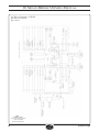
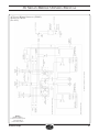
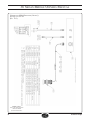
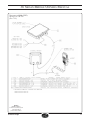
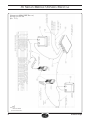
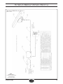
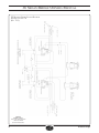
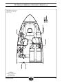
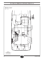
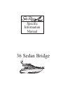
Specific
Information
Manual
36 Sedan Bridge
36 Sedan Bridge Specific Information Manual
Table of Contents
1. Load Capacity........................................................... 1
2. Passenger Locations................................................ 1
3. Safety Label Locations............................................. 2
4. Basic Boat Dimensions and Clearances ................. 5
5. Function and Location of Through-Hull Fittings and
Cutouts...................................................................... 6
6. Helm, Gauge and Switch Layout.............................. 7
7. Lower Control Station Layout (Optional)................... 7
8. Control Station Switch Panels.................................. 8
9. Deck Layout ............................................................ 9
10. Interior Layout . .................................................... 10
11. Arch...................................................................... 11
12. Hardtop (Optional)................................................ 11
13. Cleats.................................................................... 12
14. Navigation and Anchor Lights.............................. 12
A. Console Dimmer.............................................. 12
15. Bilge Layout.......................................................... 13
16. Fuel System.......................................................... 15
A. Gasoline Fuel System...................................... 15
B. Diesel Fuel System (Optional)......................... 15
17. Recommended Batteries...................................... 15
18. Fire Extinguishing System.................................... 16
19. Entertainment Centers.......................................... 16
A. TV Signal Selector.......................................... 16
B. Dockside Telephone/Television Hookup........... 16
20. MPDS................................................................... 17
A. Water Tank....................................................... 17
B. Water Pump..................................................... 17
C. Water Heater.................................................... 17
D. Gray Water Sump............................................. 17
21. Macerator Discharge Pump w/ Seacock Interlock
System (Optional)................................................... 18
22. Refrigerator & Freezer.......................................... 18
A. Cockpit Ice Maker (Optional)........................... 18
23. Stove & Microwave............................................... 19
A. Electric Stove................................................... 19
B. Microwave/Convection Oven............................ 19
24. Power Ventilation System..................................... 19
25. Spotlight................................................................ 19
26. Canvas.................................................................. 20
27. Electrical Schematic............................................. 20
Information in this publication is based upon the latest product specifications available at printing. Sea Ray®
Boats, Inc. reserves the right to make changes at any time, without notice, in the colors, equipment, specifications,
materials and prices of all models, or to discontinue models. Should changes in production models be made, Sea
Ray® is not obligated to make similar changes or modifications to models sold prior to the date of such changes.
Owner’s Manual
36 Sedan Bridge
Printed in the U.S.A. November 2007
© Sea Ray Boats, Inc. • A Brunswick Company
Sea Ray Boats, Inc. 2600 Sea Ray Blvd., Knoxville, TN 37914
For information call 1-800-SRBOATS or fax 1-314-213-7878
Internet Address: http://www.searay.com
Note: Not all accessories shown in pictures or described herein are
standard equipment or even available as options.
Options and features are subject to change without notice.
The following are registered trademarks of the Brunswick Corporation: Sea Ray ® & The SR Wave Logo
36 Sedan Bridge
i
This Page Intentionally Left Blank
ii
36 Sedan Bridge
36 Sedan Bridge Owners Manual
1. Load Capacity
Refer to the General Information Manual for a
detailed explanation of Load Capacity.
! DANGER
Never carry more weight or passengers than indicated
on the certification plate, regardless of weather or water
conditions.
The boat can capsize, swamp or sink.
Builder’s Plate (international)
(Fig. 1.1)
Boat Manufacturer
Maximum Number
of Passengers
Passenger Locations
(Fig. 1.2)
DO NOT WALK ON THIS AREA
WORKING DECK
(deck area intended for occupation during
anchoring, mooring and emergency operation only)
accommodation deck
(deck area intended for occupation during normal
operation)
!
keep off
hatch
deck hatch
(also emergency
exit)
MfG’s Model
Designation
Maximum Load
Capacity
2. Passenger Locations
Refer to the General Information Manual for a
detailed explanation of Passenger Locations.
! WARNING
Boat motion can be erratic.
You can fall overboard or be injured by hitting
something in or on the boat.
All persons must be in cockpit area or cabin and be
prepared for sudden boat movement.
Use front or bow deck area only during anchoring,
mooring or emergencies.
! WARNING
Wet decks are slippery.
You can be seriously injured if you slip and fall.
Wear slip resistant footwear secured to your feet and
hold on to rails or boat structure.
36 Sedan Bridge
! DANGER
Rotating propellers can injure or kill you.
Shut off engine when persons are in water near
boat, or on swim platform or ladder.
! WARNING
Rear facing transom seats MUST NOT be used while
engine is running or boat is moving.
1
36 Sedan Bridge Owners Manual
3. Safety Label Locations
Safety Label Locations
(Fig. 2.1)
NMMA certification tag
STAINLESS STEEL SLIDING SWIM LADDERS
SUGGESTED CARE & MAINTENANCE
AFTER EACH USE:
Fully extend ladder and thoroughly rinse all ladder and slide surfaces with
fresh water. Pay special attention to flushing any debris and salt water from
the slide areas.
MONTHLY:
Examine the ladder slide grooves and remove any foreign particles lodged
within the grooves.
Wash entire ladder, uning ONLY a clean, soft cloth, and mild soap solution.
Rinse thoroughly with fresh water. To prevent damage NEVER USE
ABRASIVES or ABRASIVE CLEANERS!
Allow ladder to dry after washing. Apply a light coating of spray lubricant or
clear silicone grease to the slide areas ONLY. Work ladder back and forth
to assure distribution of lubricant and ease of operation.
CAUTION - TO PREVENT THE POSSIBILITY OF PERSONAL INJURY,
ENSURE THAT ANY LUBRICANT IS CLEANED FROM LADDER RUNGS
AND STILES PRIOR TO USE.
Inspect the ladder for damage and check the security of all fasteners.
Repair damage and/or tighten any hardware that may have become loose
prior to use.
MRP 1573112
2
SR-7505
36 Sedan Bridge
36 Sedan Bridge Owners Manual
Safety Label Locations (Continued)
Safety Label Locations
(Fig. 3.1)
36 Sedan Bridge
3
36 Sedan Bridge Owners Manual
Safety Label Locations (Continued)
Safety Label Locations
(Fig. 4.1)
TYPICAL ON P & S
STRINGER
ON ALL BATTERY COVERS
ON ALL BATTERY COVERS
TYPICAL ON ALL J-BOX COVERS
4
36 Sedan Bridge
36 Sedan Bridge Owners Manual
4. Basic Boat Dimensions and Clearances
Boat Dimensions and Clearances
(Fig. 5.1)
WATERLINE
19’ 5.25” (5.92 m)
14’ 5” (4.39 m)
1’ 3” (0,38 m)
2’ 2”
(0.66 m)
KEEL
37’ 4” (11.38 m)
37’ 4” (11.38 m)
BEAM
13’
(3.96 m)
S PE C I FI CAT I O N S & D I M E N S I O N S
Overall Length
Hull Length
Beam
Draft Dry Weight – Standard Power
Fuel Capacity
38’ 4” (11.68 m)
37’ 4” (11.38 m)
13’ (3.96 m)
40” (1.016 m)
21, 300 lbs. ( 9.661.6 kg)
300 gal. (1,135.5 liters)
Water Capacity
75 gal. (283.9 liters)
Holding Tank
35 gal. (132.5 liters)
Dead Rise
19°
Keel To Top Of Mastlight
19’ 5 1/4” (5.92 m)
Keel To Top Of Bridge
14’ 5” (4.39 m)
Note - Dimensions can vary depending on load and running conditions.
36 Sedan Bridge
5
36 Sedan Bridge Owners Manual
5. Function and Location of Through-Hull Fittings and Cutouts
Starboard Through-Hull Fittings
(Fig. 6.1)
f
g
e
A
B
d
C
h
A generator exhaust
d
cockpit hatch drain
g rope locker hatch drain
B starboard engine exhaust
e
starboard fuel tank vent
h rope locker drain
C water heater drain
f
horn
Port Through-Hull Fittings
(Fig. 6.2)
A
B
C
d
e
f
g
h
i
j
n
l
m
k
A
head sink drain
e port fuel tank vent
i
port engine exhaust
m
salon a/c drain
B
power vent
f forward bilge pump
j
cockpit hatch drain
n
galley sink drain
C
vacuum vent (optional)
g aft bilge pump
k
shower sump
D
water tank vent
h holding tank vent
l
cabin bilge pump
Bilge Through-Hull Cutouts
(Fig. 6.3)
B
C
A
D
A
port engine underwater exhaust
B
port engine seacock
C
starboard engine seacock
D
a/c seacock
E
starboard engine underwater exhaust
E
6
36 Sedan Bridge
36 Sedan Bridge Owners Manual
6. Helm, Gauge and Switch Layout
Bridge Control Station
(Fig. 7.1)
A
E
D
B
F
C
G
u
H
I
J
t
s
r
k
q
n
p
l
m
o
A
searay navigator
B
magnetic compass
C
trim tab control
D
autopilot
E
starboard engine tachometer
F
starboard engine multi gauge
G
starboard storage
H
vhf radio handset
I
manual fire extinguisher
J
systems monitor
k
thruster control
l
throttle controls
m
helm
n
spotlight control
o
gear shift
p
stereo remote
q
switch panel
r
port storage
s
port engine multi gauge
t
port engine tachometer
u
smartcraft system view
7. Lower Control Station Layout (Optional)
Lower Control Station Layout (Optional)
(Fig. 7.2)
B
A
A
smartcraft systemview
B
autopilot
C
starboard engine tachometer
D
starboard engine multi-gauge
E
switch panel
F
mathers throttle/gear shift
G
fire extinguisher override switch
H
helm
i
spotlight
F
j
thruster control
G
k stereo remote
C
p
D
o
E
n
l
m
H
port engine multi gauge
m vhf radio handset
n port engine tachometer
o searay navigator
l
k
36 Sedan Bridge
j
i
p magnetic compass
7
36 Sedan Bridge Owners Manual
8. Control Station Switch Panels
Bridge Control Station Switch Panel
(Fig. 8.1)
A
C
B
y
x
A
B
E
D
w
F
j
i
H
G
l
k
n
m
o
v
u
automatic fire extinquisher
indicator light
engine sync
C navigation lights
D anchor light
E
dimmer
F
overhead lights
G
bridge lights
p
H spotlight
t
q
s
I
electronics switch
r
starboard engine stop switch
J
autopilot
s
starboard engine start/run switch
K
radar
t
port engine start/run switch
L
thruster main switch
u
port engine stop switch
M
accessory
v
emergency engine start switch
N
accessory
w
aft bilge pump
O
windlass main
x
forward bilge pump
p
windlass
y
horn
q
bilge blowers
r
Lower Control Station Switch Panel
(Fig. 8.2)
A
B
C
D
A
F
G
H
I
J
K
L
M
emergency engine start switch
H
N
O
p
q
r
s
t
anchor light
O
electronics
dimmer switch
p
radar
spotlight
q
autopilot
thruster main
bilge blowers
I
C
engine sync
J
D
horn
K overhead lights
r
E
forward bilge pump
L
s windlass main
F
aft bilge pump
M wiper speed control switch
G
navigation lights
N windshield washer
B
8
E
windshield wipers
t windlass
36 Sedan Bridge
36 Sedan Bridge Owners Manual
9. Deck Layout
General Layout
(Fig. 9.1)
A
aa
B
z
C
y
D
x
E
F
w
v
G
u
t
A
anchor chute
B
spotlight
C
windlass bow switches
D
port bow cleat
E
forward stateroom hatch
F
port midship cleat
G
fresh water fill deck plate
H
bridge steps
I
port aft outboard cleat
J
port fuel fill deck plate
k
port aft inboard cleat
l
telescoping swim ladder
m
transom door
n
swim platform
o
transom storage
p
starboard aft inboard cleat
q
starboard fuel fill deck plate
R
bridge seating
S
starboard aft outboard cleat
t
bridge campanion seat
u
captain’s seat
v
bridge control station
w
starboard midship cleat
x
starboard bow cleat
y
anchor locker
z
windlass
aa
anchor cleat
H
r
s
I
J
r
q
k
p
l
36 Sedan Bridge
m
n
o
9
36 Sedan Bridge Owners Manual
10. Interior Layout
General Layout, Interior
(Fig. 10.1)
A
s
r
B
C
q
D
p
E
F
o
G
H
n
I
J
k
l
A
master stateroom bunk
B
master stateroom hanging closet
C
head
D
vanity sink
E
head floor drain
F
coffee maker
G
two burner stove
H
microwave
I
freezer
J
refrigerator
k
galley sink
l
galley faucet
m
main distribution panel / entertainment center
n
dinette (upper level)
o
starboard stateroom (lower level)
p
shower floor drain
q
shower
r
forward stateroom television
s
forward stateroom skylight/emergency hatch
m
10
36 Sedan Bridge
36 Sedan Bridge Owners Manual
11. Arch
Arch
(Fig. 11.1)
D
F
C
B
E
A
vhf antenna
B
tv antenna
C
all round light
D
radar
E
searay/northstar gps antenna
(optional)
F
searay navigator vhf antenna
(Optional)
G
speakers (p&s)
A
vhf antenna
B
searay/northstar gps antenna
(optional)
C
tv antenna
D
radar
E
all round anchor light
F
searay navigator vhf antenna
(Optional)
A
G
12. Hardtop (Optional)
Hardtop (Optional)
(Fig. 11.2)
B
C
D
A
E
F
G speakers (p&S)
G
H
bridge dinette table
I
bridge guest seating
J
stern light
k
port navigation light
H
I
k
J
36 Sedan Bridge
11
36 Sedan Bridge Owners Manual
13. Cleats
Cleats must not be used for lifting the boat; they are
intended for docking or mooring use only.
Cleat / Bow & Stern Eye Locations
(Fig. 12.1)
cleat
cleat
cleat
opt to install additional equipment on the spoiler or
optional hard top, it then becomes your responsibility
to reevaluate your lighting situation to make certain
the navigation lights on your boat meet government
navigational lighting requirements. You will most
likely have to raise the mast light. Consider the
weight of the equipment you install; be certain it
is not too heavy for your sport spoiler or optional
hard top.
A. Console Dimmer
cleat
cleat
cleat
cleat
There is a DIMMER control switch located on the
control station switch panel (Figure 2.9.1) which
controls the intensity of the switch panel lights.
The switch panel lights are energized when the
navigation running lights are turned on. The gauge
lights intensity is controlled by the SmartCraftTM
Systems Monitor.
Navigation Lights
(Fig. 12.1)
14. Navigation and Anchor Lights
Navigation lights MUST be on while underway
from sunset to sunrise or in conditions of reduced
visibility. “Underway” means the boat is not docked
or at anchor. Trolling or drifting with engine off is
considered “underway” and navigation lights must
be used.
GREEN LIGHT
(VISIBLE 2
NAUTICAL MILES)
RED LIGHT
(VISIBLE 2
NAUTICAL MILES)
If you are anchored in open water, i.e. where other
boats can approach yours, you must display your
anchor light: a white light that can be seen from all
possible directions, i.e. 360 degrees.
Read the “Federal Requirements and Safety Tips
for Recreational Boats” provided in your kit.
To Operate the Running Lights:
Push RUNNING switch on control station switch
panel to the ON position.
To Operate the Anchor Lights:
Push ANCHOR switch on control station switch
panel to the ON position.
ALL-ROUND &
forward LIGHT,
WHITE LIGHT
(VISIBLE 3 NAUTICAL
MILES)
STERN LIGHT,
WHITE LIGHT
(VISIBLE 2
NAUTICAL MILES)
Your boat is equipped with a sport spoiler. If you
12
36 Sedan Bridge
36 Sedan Bridge Owners Manual
15. Bilge Layout
Bilge Layout (gas)
(Fig. 13.1)
FWD
C
d
A
B
aaa
zz
yy
xx
A forward bilge pump
B forward float switch
e
ww
C port engine strainer
vv
f
uu
d port engine seacock
e salon a/c
f port fuel tank vent
g forward bilge pump drain
g
tt
h port fuel tank
h
ss
i
rr
qq
i
port bilge blower
j
cockpit hatch drain
k holding tank vent filter
l mascerator
m port fuel fill deck plate
n bilge pump drain
pp
j
o cockpit hatch thru-hull drain
p holding tank vent
oo
k
nn
mm
l
q waste pumpout deck plate
r overboard discharge seacock
s port engine bypass exhaust
t port engine underwater exhaust
u port trim tab
m
ll
v stern thruster batteries
kk
w emergency high water float switch
jj
n
ii
o
hh
p
q
gg
r
ff
s
t
v
u
w
x
aa
y
ee
bb
z
cc
dd
x aft bilge pump
y stern thruster
z emergency high water bilge pump
aa trim tab pump
bb autopilot pump
cc autopilot rudder reference arm
dd starboard trim tab
ee starboard engine underwater exhaust
ff generator exhaust
gg starboard engine bypass exhaust
hh generator muffler
ii
starboard cockpit hatch drain
jj starbord fuel fill deck plate
kk float switch
ll hot water tank
mm generator strainer
ss oil exchanger
nn starboard fuel tank
tt starboard engine strainer
zz a/c system seacock
oo generator seacock
uu starboard fuel tank vent
aaa
pp starboard cockpit hatch drain
vv starboard battery bank
qq generator
ww
rr starboard bilge blower
xx port battery bank
36 Sedan Bridge
yy bow thruster batteries
a/c system strainer
starboard engine seacock
13
36 Sedan Bridge Owners Manual
Bilge Layout (Cont'd)
Bilge Layout (diesel)
(Fig. 14.1)
d
FWD
A
C
B
ddd
eee
ccc
bbb
aaa
A forward bilge pump
zz
B a/c system pump
e
C port engine strainer
yy
f
d port engine seacock
xx
ww
g
e salon a/c
f port fuel tank vent
g forward bilge pump drain
h port fuel tank
vv
h
i
port bilge blower
j cockpit hatch drain
uu
i
tt
k holding tank vent filter
l mascerator
m port fuel fill deck plate
n bilge pump drain
o cockpit hatch thru-hull drain
j
ss
k
p holding tank vent
q waste pumpout deck plate
rr
L
qq
pp
oo
m
n
nn
o
p
mm
q
ll
r
s
v
t
x
w
u
kk
ee
jj
cc
y
z
bb
aa
dd
gg
ff
ii
hh
r overboard discharge seacock
s port engine bypass exhaust
t port engine underwater exhaust
u port trim tab
v stern thruster batteries
w generator seacock
x emergency high water float switch
y aft bilge pump float switch
z aft bilge pump
aa stern thruster
bb emergency high water bilge pump
cc trim tab pump
dd transom light
ee autopilot pump
ff generator muffler
gg autopilot rudder reference arm
hh starboard trim tab
ii
power steering pump
jj starboard engine underwater
exhaust
kk generator exhaust
ss
starboard cockpit hatch drain
zz port engine batteries
mm starboard cockpit hatch drain
tt
starboard bilge blower
aaa
starboard engine strainer
nn starbord fuel fill deck plate
uu starboard engine fuel filter
bbb
bow thruster batteries
oo hot water tank
vv
oil exchanger
ccc
a/c system strainer
pp generator strainer
ww
starboard engine seacock
ddd
a/c system seacock
qq generator fuel filter
xx starboard engine fuel vent
eee
float switch
rr starboard fuel tank
yy starboard engine batteries
ll
14
starboard engine bypass exhaust
36 Sedan Bridge
36 Sedan Bridge Owners Manual
16. Fuel System
17. Recommended Batteries
A. Gasoline Fuel System
The following table describes the recommended
marine cranking batteries to install in your boat.
All batteries should be of the same type, age &
rating.
The 36DB has two (2) aluminum fuel tanks with a
capacity of 150 gallons (567.8 liters) each, for a total
capacity of 300 gallons (1,135.6 liters). The fuel fill
inlets are located on the port & starboard gunwales
outboard of the swim platform.
Group
Volts
CCA*
Reserve
Qty.
Engines
31
12
800
200
1
*cold cranking amps
B. Diesel Fuel System (Optional)
The diesel fuel system consists of two fuel tanks
with a total capacity of 300 gallon (1,135.6 liters),
fuel tank vent, shut-off valve, engine fuel supply and
return line, fuel filters and fuel fills.
Fuel System
(Fig. 15.1)
Application
RECOMMENDED BATTERY:
DOUGLAS BATTERY TYPE: 31DCM, ITEM NUMBER: 989 OR EQUIVALENT
DIMENSIONS: 13” x 613/16” x 101/16”
C
FWD
D
E
F
G
B
A
J
I
A starboard fuel fill
H
B starboard engine fuel feed
C port fuel fill
d port engine fuel feed
e port fuel tank
f port electric fuel valve
g port thru-hull fuel vent
h starboard thru-hull fuel vent
i starboard electric fuel valve
j starboard fuel tank
36 Sedan Bridge
15
36 Sedan Bridge Owners Manual
18. Fire Extinguishing System
The 36 DB is equipped with an automatic fire
extinguisher system located forward of the
engines on the bulkhead . In the event of a fire,
the heat sensitive automatic head will release the
extinguishant as a vapor, totally flooding the area
in fire-killing concentrations. The system indicator
light is wired to the ignition and is turned ON when
the ignition is turned ON.
Dockside TV & Telephone Connection
(Fig. 16.2)
TRANSOM
COVER PLATE
19. Entertainment Centers
DOCKSIDE
TELEPHONE
CONNECTOR
The entertainment equipment in the salon and
staterooms vary from boat to boat. Refer to the
Owner’s Manual Packet to find individual instructions
for the equipment installed on your boat.
DOCKSIDE
TELEVISION
CONNECTOR
A. TV Signal Selector
To Connect Telephone System:
The antenna/cable selector panel is located in the
cabinet below the salon television. Turn the selector
to MAX GAIN for onboard TV antenna reception.
Turn the selector to SHORE for dockside cable
reception. The selector is powered through the fuse
block behind the salon DC Distribution Panel.
1. Lift cover plate.
TV Signal Selector & Antenna Tuner
( Fig. 16.1)
2. Connect shore cord to dock telephone inlet and
then to the boat inlet.
3. Telephone system is now operational.
There are telephone jacks located in the master
stateroom and salon.
REFER TO OWNER’S MANUAL PACKET FOR
INSTRUCTIONS AND WARRANTY INFORMATION.
B. Dockside Telephone/Television Hookup
For television reception dockside, attach the
dockside television cable to the inlet located in the
starboard transom hatch.
To Connect Cable Television:
1. Unscrew and lift cover plate.
2. Screw the TV coax cable into the TV cable
connector.
3. Run the cable to the dockside receptacle and
screw coax cable into receptacle.
16
36 Sedan Bridge
36 Sedan Bridge Owners Manual
20. MPDS
C. Water Heater
The Multi-plexed Power Distribution System, (MPDS)
ties together existing power distribuion subsystems
of the boat, providing the boat owner with a userfriendly monitoring and control system.
The 6 gallon (22.7) liters)
water heater is located
in the starboard bilge.
It operates on the 120
volt shore power system
or generator. A touch
button on the AC System
page on the ESIP in the
salon activates the water
heater.
The MPDS is located in the Main Distribution Panel
located in the cabin and allows you to control:
AC Systems
DC Power Systems
Lighting Systems
Generator
Fresh & Waste Water Tanks
as well as Helm Monitoring.
A. Water Tank
The 36 DB has one (1)
75 gallon (284 liter) water
tank located forward of the
engine bulkhead under
the salon sofa.
(Fig. 17.1)
To check the water level in the tank, press the
TANKS indicator on the main module in the galley
or the ESIP in the salon and scroll the menu for
water tank information.
B. Water Pump
The fresh water system
pump and filter is located
on the aft wall of the
equipment room under
the salon steps. Turn on
by touching the FRESH
WATER button on the
ESIP panel in the salon.
(Fig. 17.2)
(Fig. 17.3)
The water heater has a check valve to prevent
hot water from back-washing into the cold water
source and a pressure relief valve to avoid damage
to the heater from over pressure or excessive
temperature.
D. Gray Water Sump
(Fig. 17.4)
The gray water from
the shower and galley
systems plus the forward
stateroom air conditioner
condensation is carried
to the shower sump or
common drains by the
gray water drain lines
located throughout the
boat.
The sump pump is fully automatic and is protected
by a breaker on the main breaker panel on the
forward engine room component board. Check the
pump and float switch for obstructions and proper
working order.
The pump comes on when there is enough water
in the sump to raise the float switch and start the
pump. If it does not come on after one or two gallons
of water drain from the shower, turn the water off
and check the pump and float switch for proper
operation.
After using the shower, it is recommended that you
run a gallon of clean water through the shower drain
to clean out soap residue. Check the pump and float
switch for obstructions and proper working order.
36 Sedan Bridge
17
36 Sedan Bridge Owners Manual
21. Macerator Discharge Pump
w/ Seacock Interlock System
(Optional)
The optional macerator
gives the boat operator
the means of discharging
the holding tank contents
directly overboard through
a seacock in the bottom of
the hull. This is available
in conjunction with the
dockside pump out.
(Fig. 18.1)
Since direct overboard (Fig. 18.2)
discharge is prohibited
in many areas, the
macerator seacock is
normally closed. The
macerator seacock is
equipped with a system
interlock switch which
prevents the operation of
the macerator when the
macerator seacock is closed. The ENABLE button
on the ESIP in the salon will be lighted when the
macerator is operational. If the light is not lighted,
it is visual confirmation the macerator seacock is
closed and that the macerator cannot be operated.
Check that the macerator seacock handle is in the
open position and the light on the switch is lighted
before operating the macerator.
To Operate the Macerator:
1.
2.
3.
Touch and release the ENABLE button on the
ESIP in the salon and open the overboard
discharge seacock located on the bilge floor .
Touch and release the PUMP button on the
ESIP.
When tank is empty, turn off the switch, touch
the ENABLE button to turn the system off and
close the waste discharge seacock.
22. Refrigerator & Freezer
The refrigerator/freezer (Fig. 18.3)
unit located in the galley
is supplied power by
the Refrigerator/
F ree z er b u t t o n
on the salon 120 volt
DCdistribution panel. To
operate dockside, connect
the shore power system,
turn the MAIN breaker(s)
ON. Then touch and release the Refrigerator/
Freezer button on the AC systems page on the
ESIP.
A. Cockpit Ice Maker
(Optional)
(Fig. 18.4)
The cockpit ice maker is
located on the portside
of the cockpit in the wall
of the bridge steps. To
operate, touch and release
the REFRIGERATOR/
FREEZER button on the
DC systems page on the
ESIP.
To Start Ice Maker:
(Fig. 18.5)
1. Make sure water tank
is full.
2. Tu r n t h e f r e s h
water pump ON
by touching and
releasing the FRESH
WATER button on the
tanks page on the ESIP panel in the salon.
3. Turn ON ice maker switch, located at the bottom
of the unit. Allow unit to cycle several times
before using ice. Refer to water system for more
information.
REFER TO OWNER’S Manual PACKET FOR
INSTRUCTIONS AND WARRANTY INFORMATION
18
36 Sedan Bridge
36 Sedan Bridge Owners Manual
23. Stove & Microwave
A. Electric Stove
To power the 120 V galley
stove, touch and release
the STOVE button on the
AC page on the ESIP,(Fig.
19.1).
(Fig. 19.1)
(Fig. 19.4)
25. Spotlight
The stove has two (2)
burners with control knobs
to provide a variation of
heat.
The 36DB spotlight is mounted on the bow.
To Operate the Spotlight:
REFER TO OWNER’S Manual PACKET FOR
INSTRUCTIONS AND WARRANTY INFORMATION.
B. Microwave/Convection Oven
The microwave/convection
oven is located in the
center upper cabinet in
the galley. To power the
microwave, touch and
release the MICROWAVE
button on the ESIP in the
salon, (Fig. 19.2).
and individually turned
on and off by the power
vent switch in the head
and VENT button on the
Main Control Module in
the galley, (Fig. 19.4).
(Fig. 19.2)
1. Touch and release the
SPOTLIGHT button
on the ESIP panel in
the salon.
(Fig. 19.5)
2. Press the POWER
button on the spotlight
pad to turn on the
spotlight.
3. Press SPEED button to
adjust the movement speed of the spotlight.
REFER TO OWNER’S MANUAL PACKET FOR
INSTRUCTIONS AND WARRANTY INFORMATION.
24. Power Ventilation System
The power ventilation
system removes stagnant
& foul air from the master
stateroom head, guest
head and galley by means
of 12 volt exhaust fans.
They are powered by the
POWER VENT button
on the salon distribution
panel, (Fig. 19.3)
36 Sedan Bridge
(Fig. 19.3)
19
36 Sedan Bridge Owners Manual
26. Canvas
Aft Curtain
The Aft Curtain extends over the cockpit area
and may be used while underway or as a storage
cover.
Zip Aft Curtain to zipper track on aft edge of spoiler
or hardtop approximately six (6) inches on both
sides of center. Next snap the center snap of curtain
at transom and continue to snap along both sides.
Complete installation by zipping up aft curtain.
R E F E R TO OW N E R ’ S M a n u a l PAC K E T
F O R I N S T RU C T I O N S A N D WA R R A N T Y
INFORMATION.
27. Electrical Schematics
This owner's manual contains electrical schematics
and wiring harness illustrations for your boat. These
electrical schematics were generated by electrical
CAD designers at the engineering division for
technical reference and service technicians. Sea
Ray® does not recommend that you attempt to work
on the boat’s electrical system yourself. Instead,
we recommend that you take your boat to your
authorized Sea Ray® dealer for service. Sea Ray®
reserves the right to change or update the electrical
system on any model at any time without notice to
the consumer and is NOT obligated to make any
updates to units built prior to changes.
20
36 Sedan Bridge
36 Sedan Bridge Owners Manual
DC Wiring Schematics
drawing no. 09-601 (1 of 7)
(Fig. 21.1)
Warning:
DO NOT attempt to
work on the electrical system
of this boat without
professional assistance.
36 Sedan Bridge
21
36 Sedan Bridge Owners Manual
DC Wiring Schematics
drawing no. 09-601 (2 of 7)
(Fig. 22.1)
Warning:
DO NOT attempt to
work on the electrical system
of this boat without
professional assistance.
22
36 Sedan Bridge
36 Sedan Bridge Owners Manual
DC Wiring Schematics
drawing no. 09-601 (3 of 7)
(Fig. 23.1)
Warning:
DO NOT attempt to
work on the electrical system
of this boat without
professional assistance.
36 Sedan Bridge
23
36 Sedan Bridge Owners Manual
DC Wiring Schematics
drawing no. 09-601 (4 of 7)
(Fig. 24.1)
Warning:
DO NOT attempt to
work on the electrical system
of this boat without
professional assistance.
24
36 Sedan Bridge
36 Sedan Bridge Owners Manual
DC Wiring Schematics
drawing no. 09-601 (5 of 7)
(Fig. 25.1)
Warning:
DO NOT attempt to
work on the electrical system
of this boat without
professional assistance.
36 Sedan Bridge
25
36 Sedan Bridge Owners Manual
DC Wiring Schematics
drawing no. 09-601 (6 of 7)
(Fig. 26.1)
Warning:
DO NOT attempt to
work on the electrical system
of this boat without
professional assistance.
26
36 Sedan Bridge
36 Sedan Bridge Owners Manual
DC Wiring Schematics
drawing no. 09-601 (7 of 7)
(Fig. 27.1)
Warning:
DO NOT attempt to
work on the electrical system
of this boat without
professional assistance.
36 Sedan Bridge
27
36 Sedan Bridge Owners Manual
Cabin DC Wiring Schematics
drawing no. 09-602
(Fig. 28.1)
Warning:
DO NOT attempt to
work on the electrical system
of this boat without
professional assistance.
28
36 Sedan Bridge
36 Sedan Bridge Owners Manual
Cabin DC Wiring Schematics
drawing no. 09-602
(Fig. 29.1)
Warning:
DO NOT attempt to
work on the electrical system
of this boat without
professional assistance.
36 Sedan Bridge
29
36 Sedan Bridge Owners Manual
Cabin DC Wiring Schematics
drawing no. 09-602
(Fig. 30.1)
Warning:
DO NOT attempt to
work on the electrical system
of this boat without
professional assistance.
30
36 Sedan Bridge
36 Sedan Bridge Owners Manual
Cabin DC Wiring Schematics
drawing no. 09-602
(Fig. 31.1)
Warning:
DO NOT attempt to
work on the electrical system
of this boat without
professional assistance.
36 Sedan Bridge
31
36 Sedan Bridge Owners Manual
Cabin DC Wiring Schematics
drawing no. 09-602
(Fig. 32.1)
Warning:
DO NOT attempt to
work on the electrical system
of this boat without
professional assistance.
32
36 Sedan Bridge
36 Sedan Bridge Owners Manual
Cabin DC Wiring Schematics
drawing no. 09-602
(Fig. 33.1)
Warning:
DO NOT attempt to
work on the electrical system
of this boat without
professional assistance.
36 Sedan Bridge
33
36 Sedan Bridge Owners Manual
Main Negatives, Grounding and Bonding Schematic
drawing no. 09-603
(Fig. 34.1)
Warning:
DO NOT attempt to
work on the electrical system
of this boat without
professional assistance.
34
36 Sedan Bridge
36 Sedan Bridge Owners Manual
Engine Harness Schematic
drawing no. 09-604
(Fig. 35.1)
Warning:
DO NOT attempt to
work on the electrical system
of this boat without
professional assistance.
36 Sedan Bridge
35
36 Sedan Bridge Owners Manual
Engine Harness Schematic
drawing no. 09-604
(Fig. 36.1)
Warning:
DO NOT attempt to
work on the electrical system
of this boat without
professional assistance.
36
36 Sedan Bridge
36 Sedan Bridge Owners Manual
Engine Harness Schematic
drawing no. 09-604
(Fig. 37.1)
Warning:
DO NOT attempt to
work on the electrical system
of this boat without
professional assistance.
36 Sedan Bridge
37
36 Sedan Bridge Owners Manual
Engine Harness Schematic
drawing no. 09-604
(Fig. 38.1)
Warning:
DO NOT attempt to
work on the electrical system
of this boat without
professional assistance.
38
36 Sedan Bridge
36 Sedan Bridge Owners Manual
Engine Harness Schematic
drawing no. 09-604
(Fig. 39.1)
Warning:
DO NOT attempt to
work on the electrical system
of this boat without
professional assistance.
36 Sedan Bridge
39
36 Sedan Bridge Owners Manual
Engine Harness Schematic
drawing no. 09-604
(Fig. 40.1)
Warning:
DO NOT attempt to
work on the electrical system
of this boat without
professional assistance.
40
36 Sedan Bridge
36 Sedan Bridge Owners Manual
Engine Harness Schematic
drawing no. 09-604
(Fig. 41.1)
Warning:
DO NOT attempt to
work on the electrical system
of this boat without
professional assistance.
36 Sedan Bridge
41
36 Sedan Bridge Owners Manual
LWR Station DC Wiring
drawing no. 09-605
(Fig. 42.1)
Warning:
DO NOT attempt to
work on the electrical system
of this boat without
professional assistance.
42
36 Sedan Bridge
36 Sedan Bridge Owners Manual
LWR Station DC Wiring
drawing no. 09-605
(Fig. 43.1)
Warning:
DO NOT attempt to
work on the electrical system
of this boat without
professional assistance.
36 Sedan Bridge
43
36 Sedan Bridge Owners Manual
System Monitor Schematic
drawing no. 09-606
(Fig. 44.1)
Warning:
DO NOT attempt to
work on the electrical system
of this boat without
professional assistance.
44
36 Sedan Bridge
36 Sedan Bridge Owners Manual
Windlass Schematic
drawing no. 09-610
(Fig. 45.1)
Warning:
DO NOT attempt to
work on the electrical system
of this boat without
professional assistance.
36 Sedan Bridge
45
36 Sedan Bridge Owners Manual
Stereo Wiring Diagram
drawing no. 09-611
(Fig. 46.1)
Warning:
DO NOT attempt to
work on the electrical system
of this boat without
professional assistance.
46
36 Sedan Bridge
36 Sedan Bridge Owners Manual
Bow Thruster Schematic
drawing no. 09-616
(Fig. 47.1)
Warning:
DO NOT attempt to
work on the electrical system
of this boat without
professional assistance.
36 Sedan Bridge
47
36 Sedan Bridge Owners Manual
Engine Schematic (Gas)
drawing no. 09-618
(Fig. 48.1)
Warning:
DO NOT attempt to
work on the electrical system
of this boat without
professional assistance.
48
36 Sedan Bridge
36 Sedan Bridge Owners Manual
Engine Schematic (Gas)
drawing no. 09-618
(Fig. 49.1)
Warning:
DO NOT attempt to
work on the electrical system
of this boat without
professional assistance.
36 Sedan Bridge
49
36 Sedan Bridge Owners Manual
Engine Schematic (Gas DTS)
drawing no. 09-619
(Fig. 50.1)
Warning:
DO NOT attempt to
work on the electrical system
of this boat without
professional assistance.
50
36 Sedan Bridge
36 Sedan Bridge Owners Manual
Engine Schematic (Gas DTS)
drawing no. 09-619
(Fig. 51.1)
Warning:
DO NOT attempt to
work on the electrical system
of this boat without
professional assistance.
36 Sedan Bridge
51
36 Sedan Bridge Owners Manual
Engine Schematic (Cummins QSB)
drawing no. 09-620
(Fig. 52.1)
Warning:
DO NOT attempt to
work on the electrical system
of this boat without
professional assistance.
52
36 Sedan Bridge
36 Sedan Bridge Owners Manual
Engine Schematic (Cummins QSB)
drawing no. 09-620
(Fig. 53.1)
Warning:
DO NOT attempt to
work on the electrical system
of this boat without
professional assistance.
36 Sedan Bridge
53
36 Sedan Bridge Owners Manual
Engine Schematic (Diesel Dual Station)
drawing no. 09-621
(Fig. 54.1)
Warning:
DO NOT attempt to
work on the electrical system
of this boat without
professional assistance.
54
36 Sedan Bridge
36 Sedan Bridge Owners Manual
Engine Schematic (Diesel Dual Station)
drawing no. 09-621
(Fig. 55.1)
Warning:
DO NOT attempt to
work on the electrical system
of this boat without
professional assistance.
36 Sedan Bridge
55
36 Sedan Bridge Owners Manual
Interconnect
drawing no. 09-622
(Fig. 56.1)
Warning:
DO NOT attempt to
work on the electrical system
of this boat without
professional assistance.
56
36 Sedan Bridge
36 Sedan Bridge Owners Manual
Gas Generator (Non ECD)
drawing no. 09-623
(Fig. 57.1)
Warning:
DO NOT attempt to
work on the electrical system
of this boat without
professional assistance.
36 Sedan Bridge
57
36 Sedan Bridge Owners Manual
Gas Generator (ECD)
drawing no. 09-624
(Fig. 58.1)
Warning:
DO NOT attempt to
work on the electrical system
of this boat without
professional assistance.
58
36 Sedan Bridge
36 Sedan Bridge Owners Manual
Diesel Generator
drawing no. 09-625
(Fig. 59.1)
Warning:
DO NOT attempt to
work on the electrical system
of this boat without
professional assistance.
36 Sedan Bridge
59
36 Sedan Bridge Owners Manual
AC Wiring Schematic (120/60)
drawing no. 09-630
(Fig. 60.1)
Warning:
DO NOT attempt to
work on the electrical system
of this boat without
professional assistance.
60
36 Sedan Bridge
36 Sedan Bridge Owners Manual
AC System Wiring Schematic (120/60)
drawing no. 09-631
(Fig. 61.1)
Warning:
DO NOT attempt to
work on the electrical system
of this boat without
professional assistance.
36 Sedan Bridge
61
36 Sedan Bridge Owners Manual
AC Wiring Diagram (220/50)
drawing no. 09-632
(Fig. 62.1)
Warning:
DO NOT attempt to
work on the electrical system
of this boat without
professional assistance.
62
36 Sedan Bridge
36 Sedan Bridge Owners Manual
AC System Diagram (120VAC)
drawing no. 09-640
(Fig. 63.1)
Warning:
DO NOT attempt to
work on the electrical system
of this boat without
professional assistance.
36 Sedan Bridge
63
36 Sedan Bridge Owners Manual
AC System Diagram (220VAC)
drawing no. 09-641
(Fig. 64.1)
Warning:
DO NOT attempt to
work on the electrical system
of this boat without
professional assistance.
64
36 Sedan Bridge
36 Sedan Bridge Owners Manual
Smartcraft Systems Wiring (Gas)
drawing no. 09-701
(Fig. 65.1)
Warning:
DO NOT attempt to
work on the electrical system
of this boat without
professional assistance.
36 Sedan Bridge
65
36 Sedan Bridge Owners Manual
Smartcraft Wiring (Diesel)
drawing no. 09-702
(Fig. 66.1)
Warning:
DO NOT attempt to
work on the electrical system
of this boat without
professional assistance.
66
36 Sedan Bridge
36 Sedan Bridge Owners Manual
Smartcraft Wiring (Diesel)
drawing no. 09-702
(Fig. 67.1)
Warning:
DO NOT attempt to
work on the electrical system
of this boat without
professional assistance.
36 Sedan Bridge
67
36 Sedan Bridge Owners Manual
Nortrhstar 6000i
drawing no. 09-740
(Fig. 68.1)
Warning:
DO NOT attempt to
work on the electrical system
of this boat without
professional assistance.
68
36 Sedan Bridge
36 Sedan Bridge Owners Manual
Nortrhstar 6000i (Dual Display)
drawing no. 09-742
(Fig. 69.1)
Warning:
DO NOT attempt to
work on the electrical system
of this boat without
professional assistance.
36 Sedan Bridge
69
36 Sedan Bridge Owners Manual
Nortrhstar 6000i (Fishfinder (Option))
drawing no. 09-743
(Fig. 70.1)
Warning:
DO NOT attempt to
work on the electrical system
of this boat without
professional assistance.
70
36 Sedan Bridge
36 Sedan Bridge Owners Manual
Nortrhstar 6000i (VHF)
drawing no. 09-745
(Fig. 71.1)
Warning:
DO NOT attempt to
work on the electrical system
of this boat without
professional assistance.
36 Sedan Bridge
71
36 Sedan Bridge Owners Manual
Nortrhstar 6000i (VHF Deluxe)
drawing no. 09-746
(Fig. 72.1)
Warning:
DO NOT attempt to
work on the electrical system
of this boat without
professional assistance.
72
36 Sedan Bridge
36 Sedan Bridge Owners Manual
Northstar 6000i (Radar) (Option)
(Fig. 73.1)
Warning:
DO NOT attempt to
work on the electrical system
of this boat without
professional assistance.
36 Sedan Bridge
73
36 Sedan Bridge Owners Manual
ZF Mathers Cruise System Diagram
drawing no. 09-770
(Fig. 74.1)
Warning:
DO NOT attempt to
work on the electrical system
of this boat without
professional assistance.
74
36 Sedan Bridge
36 Sedan Bridge Owners Manual
EDS Module Layout
drawing no. 09-502
(Fig. 75.1)
Warning:
DO NOT attempt to
work on the electrical system
of this boat without
professional assistance.
36 Sedan Bridge
75
36 Sedan Bridge Owners Manual
EDS Module Layout
drawing no. 09-502
(Fig. 76.1)
Warning:
DO NOT attempt to
work on the electrical system
of this boat without
professional assistance.
76
36 Sedan Bridge
36 Sedan Bridge Owners Manual
EDS Module Layout
drawing no. 09-502
(Fig. 77.1)
Warning:
DO NOT attempt to
work on the electrical system
of this boat without
professional assistance.
36 Sedan Bridge
77
this page intentionally left blank
Index
A
I
Arch............................................................................ 11
Anchor Lights.............................................................. 16
Interior Layout............................................................. 10
B
L
Load Capacity............................................................... 1
Batteries, Recommended........................................... 15
Bilge Layout...........................................................13-14
M
C
Cabin Layout.............................................................. 12
Central Vacuum System............................................. 16
D
Macerator................................................................... 18
MPDS......................................................................... 17
Microwave................................................................... 19
N
Navigation Lights........................................................ 12
Deck Layout.................................................................. 9
Dimensions................................................................... 5
P
E
Passenger Locations.................................................... 1
Power Ventilation Systems......................................... 19
Electrical Schematics............................................20-78
Entertainment Center................................................. 16
S
F
Safety Label Locations..............................................2-4
Switch Layout............................................................... 8
Fire Extinguishing System.......................................... 16
Fuel System................................................................ 15
T
H
Through-Hull Fittings.................................................... 6
Hardtop....................................................................... 11
36 Sedan Bridge
Index i
Index
THIS PAGE LEFT INTENTIONALLY BLANK
Index ii
36 Sedan Bridge