1
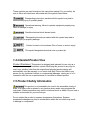
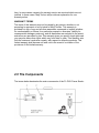
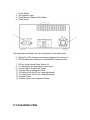
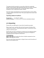
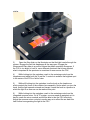
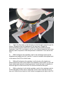
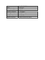
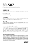
Model FL-PWJ Power Supply
Model FL-LHJ Lamphouse
Instruction Manual
Table of Contents
1.0 Introduction
1.1 Power Supply & Lamphouse Features
1.2 General Safety Guidelines
1.3 Warning/Caution symbols used in this manual
1.4 Intended Product Use Statement
1.5 Product Safety Information
1.6 Warranty Notes
2.0 The Components
2.1 Installation Site
2.2 Unpacking
2.3 Set Up
2.4 Bulb Installation or Replacement, Step-by-Step
2.5 Bulb Alignment for TC Models
2.6 Bulb Alignment for MT Models
3.0 Operation
3.1 UV Light Safety Considerations
4.0 Maintenance and Cleaning
5.0 Troubleshooting
5.1 Fluorescence Lamp does not work
5.2 Replacing the Fluorescence Lamp
6.0 Specifications
Model FL-PWJ Power Supply & FL-LHJ
Lamphouse
1. Introduction
The Meiji Techno FL-PWJ Epi-Fluorescence Illuminator Power Supply is a
precision engineered product incorporating efficient, silent-running switchmode
power supply technology delivering smooth, regulated current.
The FL-PWJ Power Supply is designed only to support 100 watt HBO DC arc
lamps.
The advanced switchmode design provides constant, low-noise DC power that
automatically adjusts for the condition of the DC lamp in circuit.
The FL-PWJ Power Supply comes standard with a panel mounted circuit breaker
and provides accidental unplug protection to guard against laboratory mishaps.
A panel mounted Elapsed Time Panel Meter keeps track of the DC arc lamp
hours in use so replacements can be easily accommodated.
The reset button on the panel meter resets to “zero” when arc lamps are
replaced.
This system was designed for easy plug-n-play integration with 100 watt HBO
illumination commonly used in fluorescence microscopy work with no additional
adjustments necessary for the lifespan of the arc lamp.
The FL-PWJ Power Supply can be used with the TC Series Inverted EpiFluorescence Microscope and comes standard on the MT6000 Series EpiFluorescence Upright Biological Models.
1.1 Power Supply & Lamphouse Features
•
•
•
•
•
•
•
•
•
•
•
•
Integrated Focusing Collector Lens in Lamphouse
Integrated Concave Mirror optimizes DC Arc Components
Solid State Switchmode Type Power Supply
Supports 100watt HBO Mercury DC arc lamps
Warm up time: ~ 2 minutes
Elapsed Time Meter
Power Supply & Lamphouse are Convection Cooled ( no fan noise )
Resetable Front Panel Breaker
Accidental Unplug Protection on Output
CE Approved, UL pending
1 year Conditional Warranty
Country of Origin: Japan
1.2 General Safety Guidelines
This manual contains important safety instructions and information concerning
the installation, operation and maintenance of the FL-PWJ Power Supply.
This manual should be read carefully before any attempt is made to operate this
equipment. To ensure safe operation the user must read and adhere to all of the
directions put forth in this manual.
Meiji Techno products are designed for safe operation under normal operating
conditions. The instrument and accessories described in this manual have been
built and tested according to industry safety standards for electronic laboratory
instruments. Incorrect usage or non-conformance to operating instructions can
cause personal injury or damage to equipment or property.
Keep this manual near your instrument for easy reference.
1.3 Warning/Caution Symbols Used in this Manual
You must be aware of all safety issues when you install and operate this
microscope system. Several warning and caution symbols are listed below.
These symbols are used throughout this instruction manual. For your safety, be
sure to follow all instructions associated with the symbols listed below.
Disregarding instructions marked with this symbol may lead to
serious bodily injury or possibly death.
Operational warning; failure to operate equipment properly may
result in damage or injury.
Possible electrical shock hazard exists
Disregarding instructions marked with this symbol may lead to
serious injury or property damage.
Caution for heat or hot surfaces. Risk of burns or serious injury!
This symbol designates technical note or product tip.
1.4 Intended Product Use
Product Disclaimer: This product is designed and intended for use only as a
biological microscope illumination system. Modifying this product in any way for
use in any situation other than the original and intended product design will
automatically void the warranty. In no event shall Meiji Techno be liable to any
person for any incidental, indirect or consequential damages, arising out of or in
connection with the use or performance of a modified or altered product.
1.5 Product Safety Information
This product is not intended to be used in the immediate vicinity of
water or a water outlet or placed in any location where water may penetrate the
instrument. Water penetration may result in electrical shock or death. Choose only a
suitable environment for your microscope.
Do not subject the product to extreme temperature fluctuations. Extreme
temperature changes may lead to condensation within the unit which may result
in damage to components.
Disassembly of the product may result in electrical shock, injury or death,
equipment damage, loss of warranty coverage or may create other potential
hazardous consequences.
Always turn off the power switch and disconnect the cord from the power supply
when replacing fuses, connecting or disconnecting wiring, doing general
maintenance or replacing the DC arc lamp.
DO NOT OPERATE UNLESS THE UNIT IS PROPERLY GROUNDED!
Use only the specified power cord in a well grounded socket. Do not use in an
ungrounded power receptacle or in cases where there is a break in the ground
conductor or damage to the electrical wiring.
Only fuses of the specified type and rating are to be used as replacements.
Switch off the power and disconnect the power cord before replacing fuses. Use
of a non-compliant fuse may result in electrical shock or severe damage your
equipment.
The lamp and lamp house become extremely hot during and after operation. Do
not place any highly flammable or volatile material close to the lamp-house
during or after operation. Do not touch the lamp house or attempt to replace the
bulb for at least 30 minutes after the unit has been turned off or injury may result.
Do not obstruct the air vents on the lamp-house or power supply. The lamp
housing and power supply should must be located at least 10 cm (4 inches) away
from the nearest wall or any combustible objects.
Modifying the product in any way or unauthorized attempts to disassemble or use
the instrument for applications other then its intended design will automatically
void the warranty.
1.6 Warranty Notes
Meiji Techno warrants this product against defects in material and/or workmanship for
one year from the date of the original purchase to the original purchaser. Meiji Techno will
repair or replace, at its option, any product which under normal conditions of use and
service proves to be defective in material or workmanship. No charge will be made for
labor or materials with respect to defects covered by this warranty, provided all repair
work is done by Meiji Techno.
This warranty does not cover expenses incurred in the removal or reinstallation of any
instrument or instruments, whether or not proven defective. Replacement or repairs
furnished under this warranty are subject to the same terms and conditions of the original
warranty. This warranty supersedes any other warranty and is subject to the following
terms and conditions:
WARRANTY
Warranty of Meiji Techno products extends to the original purchaser of the
product and is not transferable.
WARRANTY DURATION
Meiji Techno warrants this product against defects in material and/or
workmanship for the life of the product from the date of original purchase to the
original purchaser. The electrical warranty is limited to one year.
OWNER’S REGISTRATION CARD
Return of the owner’s registration card by the original purchaser within ten (10)
days after the original purchase is a condition precedent to coverage under this
warranty. Meiji Techno will at its option accept written proof of purchase from the
original owner in lieu of a product registration card.
EXCLUSIONS AND LIMITATIONS
Specifically excluded from this warranty are failures caused by abuse, neglect,
misuse, improper operation, normal wear, accident, improper maintenance or
modifications of ANY type. This warranty does not cover repair or replacement
where normal use has exhausted the life of a part, product or instrument. All
mechanical devices need periodic parts replacement and service to perform well.
Service life of a product is dependent upon the care it receives and the
conditions under which it has to operate. In no event shall Meiji Techno be liable
for incidental or consequential damages.
SERVICE
To obtain service under this warranty, please contact Meiji Techno directly and
ask for the Product Service Department. State the nature of the problem, model
and serial number of the product, date of purchase and location and name of the
distributor the instrument was purchased from. After verification of warranty
registration, Meiji Techno will issue a return authorization number. Customer may
then return the product postage prepaid and insured to the authorized repair
facility.
In most instances, requests for warranty service will be performed in a prompt
and routine manner and merchandise will be returned in a reasonable period of
time. In some cases, requests for warranty service are received which are not
justified. In these cases, Meiji Techno will provide an explanation for nonwarranty action.
WARRANTY TERMS
The terms of this warranty may not be varied by any person, whether or not
purporting to represent or act on behalf of Meiji Techno. This warranty is
provided is in lieu of any and all other warranties, expressed or implied, whether
for merchantability or fitness for a particular purpose or otherwise. Liability for
consequential damages under any, and all warranties are excluded to the extent
exclusions are permitted by law. This warranty gives you specific legal rights and
you may also have other rights which vary from state to state. This warranty sets
forth the customer’s exclusive remedy, with respect to defective products. This
limited warranty shall become null and void in the event of a violation of the
provisions of this limited warranty.
2.0 The Components
The image below designates the main components of the FL-PWJ Power Supply.
1.
2.
3.
4.
Power Switch
Run Indicator Lamp
Panel Mounted Elapsed Time Meter
Reset Button
The image above indicates the main components of the back panel.
5. Output Port (The Lamphouse harness plugs into this connector.)
6. IEC Standard inlet connector for standard IEC powercord sets.
7. DC Arc Lamp Access Panel Screws (2)
8. X-Y adjustment for integrated concave mirror
9. Concave Mirror Position Set Screw
10. Concave Mirror Adjustment Knob
11. X Position Knob for DC Arc Lamp Adjustment
12. Y Position Knob for DC Arc Lamp Adjustment
13. Dovetail Fitting
14. Collector Lens Focus Adjustment Knob
2.1 Installation Site
The system should be operated in a room with as little dust as practically
possible. Keep the power supply and lamphouse away from solvents, chemical
fumes and excessive humidity. Also try to avoid big swings in ambient
temperature, direct sunlight and excessive vibration.
The power supply needs adequate room around the housing to receive airflow.
The power supply should have at least 10cm space away from the nearest wall
or obstruction.
Operating Ambient Conditions
Temperature:
0 - 40°C (32 – 96.8°F)
Relative Humidity: 20 – 80% up to 30°C (No dew condensation allowed)
2.2 Unpacking
Please check your packing slip to insure that all materials are present.
Keep a copy for your records so that you have the proper information when
ordering more equipment, ordering replacement parts or accessories or when
calling for technical support.
Please make sure that no small pieces or parts are left in the packing material.
Keep the packing materials in a safe place for the purpose of storage and
transporting the microscope and its accessories.
Avoid touching the surface of optical components such as
lenses, filters and glass surfaces.
Even very small traces of perspiration or finger oils can corrode the surfaces of
optics in a short period of time.
2.3 Set Up
•
•
•
•
As a first step, remove all components from the shipping container and
remove the packing materials. Save the container and packing in a dry
location.
Remove the access plate on the lamp house by unscrewing the two knobs
counter-clockwise until they stop and gently removing the access plate.
If the DC Arc lamp is not installed, proceed to install the DC arc lamp in
the correct orientation shown below being careful not to touch the glass
portion of the DC Arc Lamp:
Once the connections are made snugly, re-install the lamp house cover
plate and tighten the two access plate screws making sure the captive
hardware did engage and that the access plate is tight and flat to the
housing.
•
•
Mount the lamp house onto the microscope. The three screws that engage
the dovetail fitting should be equally tight, the lamp house should be
mounted perpendicular and the lamp house should not be able to turn in
its mount when tightened properly.
Connect the cable assembly from the lamp house to the power supply
being mindful of the position and polarity of the connector. Match the pins
from the cable to the panel connector. When properly aligned, the cable
connector twists and engages the panel connector and screws all-the-way
inwards.
The power supply is ready to be plugged into the wall using a standard localized
cordset.
The mains power cord should only be plugged into a known grounded
outlet.
Contact your facilities technician if you are unsure of your mains outlet status. A
simple outlet tester can be used to verify correct outlet polarity and the presence
of a grounded circuit.
If no other accessories are going to be installed, the power supply is now ready
for use.
2.4 Bulb Installation
It is critical to properly install the bulb in the socket. Reversed polarity can
dramatically shorten the life expectancy of the particular bulb to as little as one or
two minutes followed by a very loud explosion. The writing on the base of the
bulb goes down on Mercury lamps.
When installing the bulb, the fat positive (+) end of the bulb goes into the clamp
and is tightened with the allen wrench.
Take steps to insure that the glass part of the bulb is not
touched as oils from fingers will degrade the glass and
cause pre-mature failure.
If you have any difficulty inserting a new lamp into the socket, it may be possible
that the stamping (lettering) on the bulb could be too raised. To insure a good
contact, the bulb must fit down completely into the socket. A small file can be
used to file down the letter stamping on the lamp.
Notice the larger lamp mount with the 2 set screws. This is the side that will
accept the larger (+) end of either the 100-watt Mercury lamps:
Ushio #
(-) Connection Cathode
(HBO) USH-102DH
7.5 mm Ø
(+) Connection Anode
9 mm Ø
Step by Step Instructions
1. Set the lamp house panel down on a work surface such that the lamp mount
faces you.
2. Plug the gold pin of the trigger lead into high voltage receptacle, if not already
installed.
3. Slide desired lamp into the lamp holder.
4. Slide the bulb clamp onto the negative (-) end of the lamp.
5. Hold the bulb clamp and trigger lead. Using the supplied allen wrench, tighten
the clamping screws snugly and evenly. Be careful not to place ANY stress
on the lamp.
6. Tighten two set screws on (+) side of lamp.
7. Pick up side panel with mounted lamp. Note markings on side panel. Rotate
panel until appropriate end has the text and indexer aligned correctly.
8. Insert panel in lamp house opening. Rotate and tighten the two black knobs
clockwise to lock the door.
9. Plug the socket into the power supply and plug the power supply into the
outlet.
10. Ignite lamp by turning on the power supply and adjust lamp house controls to
get proper arc alignment within the field of view.
Refer to the microscope instructions for more information regarding arc
alignment. Once alignment has been set, it will not need any further adjustment
until a new bulb is installed.
If you have any problems with this procedure, please contact your microscope
sales person.
PROPER SAFETY GOGGLES AND PROTECTION ARE
NECCESARY WHEN OPERATING EQUIPMENT THAT HAS ULTRA-VIOLET
LIGHT CONTENT.
11. A new bulb should ALWAYS be run for two hours initially to stabilize the arc
of the lamp.
2.5 Bulb Alignment – TC Models
After the bulb has burned in, the system is ready for arc lamp alignment.
There are many methods to accomplish arc lamp alignment if one were to go
look on the internet. The following is only one of many methods.
1)
If the arc lamp is not already burning, turn on the power supply and let the
arc lamp “settle” for at least 5 minutes.
2)
On the stage of the TC, place a piece of plastic on the stage that
fluoresces with any of the filter sets installed as shown below. One may have to
find the appropriate color of plastic that fluoresces with the filter sets you have or
buy a set of fluorescing slides from Chroma Technology Inc or
similar.
3)
Open the filter slider on the illuminator so that the light travels through the
system. Engage the field iris diaphragm all the way open. Engage the
fluorescence filter slider to a position where the plastic specimen fluoresces. If
the FOV is too bright to look at, use a different specimen that is less affected,
what is important is the specimen is consistent or even across the FOV.
4)
While looking into the eyetubes, reach to the centering controls on the
lamphouse and adjust both the X and the Y controls to achieve the brightest spot
in the center of the FOV or field of view.
5)
While still looking into the eyetubes, turn the knob on the lamphouse
which controls the focus of the collector lens assembly. Notice when you turn the
knob, that the light spreads outward and inward. Leave the knob in a position in
which the light is as even as can be made at this point.
6)
While looking into the eyetubes, reach to the centering controls on the
integrated concave mirror. On a TC system, one may need an assistant as it is
hard to reach the mirror controls and still be able to see the FOV effectively.
Adjust the concave mirror controls in such a way as to reflect the arc back into
itself further homogenizing the light in the FOV.
7)
Check the effect achieved when the collector lens focus knob is adjusted
and continue to make minor adjustments to the arc position and the mirror
position until the light is as even and centered in the FOV as possible.
8)
Remove the plastic slide and place a known good biological fluorescence
sample on the stage and again check the effect achieved when the collector lens
knob is adjusted and continue to make minor adjustments to the arc position and
the mirror position until the FOV displays an even an image as possible.
9) If a shadow is seen the FOV, you do not have the field iris centered AND the
field iris not open all-the-way.
2.6 Bulb Alignment – MT Models
After the bulb has burned in, the system is ready for arc lamp alignment.
There are many methods to accomplish arc lamp alignment if one were to go
look on the internet. The following is only one of many methods.
1)
If the arc lamp is not already burning, turn on the power supply and let the
arc lamp “settle” for at least 5 minutes.
2)
On the stage of the MT, place a piece of plastic on the stage that
fluoresces with any of the filter sets installed as shown below. One may have to
find the appropriate color of plastic that fluoresces with the filter sets you have or
buy a set of fluorescing slides from Chroma Technology Inc or
similar.
3)
Open the filter slider on the illuminator so that the light travels through the
system. Engage the field iris diaphragm all the way open. Engage the
fluorescence filter selector wheel into a position where the plastic specimen
fluoresces. If the FOV is too bright to look at, use a different specimen that is less
affected, what is important is that the specimen is consistent or even across the
FOV.
4)
While looking into the eyetubes, reach to the centering controls on the
lamphouse and adjust both the X and the Y controls to achieve the brightest spot
in the center of the FOV or field of view.
5)
While still looking into the eyetubes, turn the knob on the lamphouse
which controls the focus of the collector lens assembly. Notice when you turn the
knob, that the light spreads outward and inward. Leave the knob in a position in
which the light is as even across the FOV as can be made at this point.
6)
While continuing to look into the eyetubes, reach to the centering controls
on the integrated concave mirror. Adjust the concave mirror controls in such a
way as to reflect the arc back into itself further homogenizing the light in the FOV.
7)
Check the effect achieved when the collector lens focus knob is adjusted
and continue to make minor adjustments to the arc position and the mirror
position until the light is as even in the FOV as possible.
8)
Remove the plastic slide and place a known good biological fluorescence
sample on the stage and again check the effect achieved when the collector lens
knob is adjusted and continue to make minor adjustments to the arc position and
the mirror position until the FOV displays an even an image as possible.
9)
If a shadow is seen the FOV, you do not have the field iris centered AND
the field iris not open all-the-way.
3.0 Operation
Once the microscope has been setup in its working location with all of the
components correctly installed, it is ready for use.
Do not install any bulb in your instrument other than the ones designated by Meiji
Techno.
For the Epi-Fluorescence Lamphouse, the following part number is the ONLY
recommended replacement bulb:
BA005 Replacement Mercury Lamp HBO 100W/2
Always disconnect the power cord from the back of the power supply when not
being used, when cleaning your instrument or when making any repairs.
Avoid Dismantling
Never attempt to dismantle the power supply. This will void your warranty and
could possibly lead to the product no longer performing accurately.
3.1 UV Light Safety Considerations
Mercury arc lamps have intense UV light content in their output. The U.S.
National Institute for Occupational Safety and Health (NIOSH) recommends that
exposure to UV energy be controlled and limited as much as practically possible.
Exposure to UV radiation even for very brief periods of time can be hazardous.
The potential damage depends on exposure time, the type of UV light and
individuals with sensitivity to UV.
UV light causes sunburn. Long term exposure can result in loss of skin elasticity
initially and carcinoma eventually.
Absorption of UV light by the eyes will cause inflammation of the cornea called
photo keratisis. Continued exposure can lead to the formation of cataracts on the
eye lens.
Therefore, the following safety considerations should be taken very seriously:
•
•
•
•
•
•
Limit access to areas where UV light is present.
Post warning signs in the area where the equipment is installed.
Always wear protective eyewear and gloves.
Be sure your arms and neck are covered.
Never directly look at the light source.
Close off the light source with the filter slider when not being used.
4.0 Maintenance and Cleaning
•
Disconnect the power cord on your equipment prior to performing
cleaning, maintenance or repair.
•
Keep electrical components away from moisture or humidity.
•
In warm humid climates, take special care to prevent your equipment from
exposure to fungal growth.
Dust Protection
Be sure to use the supplied dust cover with your microscope after each work
session.
Cleaning
Dust and fibers can cause “background fluorescence” during fluorescence
microscopy so keeping your microscope clean can help the overall quality of your
work.
Cleaning of Painted Surfaces
Use a soft brush or lint-free cotton cloth to removed dust and loose particles.
Tough dirt can be removed with some water and a mild detergent.
NEVER USE ACETONE OR OTHER HARSH CHEMICALS.
Painted or plastic surfaces should not be tarnished or etched with cleaning
agents that are too powerful.
To clean painted surfaces, use a moistened lint-free cotton cloth with mild soapy
water.
5.0 Troubleshooting
Meiji Techno products are manufactured in Japan under ISO9000 manufacturing
standards. However, if you ever have any difficulty with any Meiji product, feel
free to contact us at:
Meiji Techno America
3010 Olcott St
Santa Clara, CA 95054
800.832.0060
408.970.4799 FAX
[email protected]
http://www.meijitechno.com
Our technical staff is trained to assist you on mechanical or electrical issues you
may have.
Problems in regard to specimens, fluorochrome fluorescence, specimen
preparation, specimen staining, etc. are beyond the scope of this manual.
5.1 Fluorescence Lamp does not work
LAMPHOUSE MAY BE HOT TO THE TOUCH.
Do not touch the glass envelope of the lamp at any time. Keep the protective
sleeve or bag of the lamp during installation and remove it right after installation.
•
•
•
Make sure that all cable connections between the lamp house, power unit
and mains are all properly established.
Check if the lamp house power unit main fuse is intact.
Check the logged hours of the lamp for an excess of 200 hours.
5.2 Replacing the Fluorescence Lamp
Refer to the companion manual of the Nobska Lamphouse for
more on troubleshooting and replacement of the 100W Mercury
Lamp.
Replacing the mercury HBO lamp within the Nobska housing is not very complex
but there is a followed procedure that will make the process easier and less
dangerous.
If the glass envelope of the mercury bulb happens to break open, you and the
immediate environment could be exposed to mercury which is a known
biohazard.
Please refer to sections 2.4 through 2.6 for information and instructions for
replacing, adjusting and burning in your new mercury lamp.
6.0 Specifications
Input
90 – 132 VAC 50-60Hz
Output
Output Stability (Ripple)
20VDC @ 5A
< 2.5% P-P
Starting Voltage Peak
Operating Temperature
2.3KV DC
0 – 40 degrees C
Operating Humidity
Storage Temperature
20% - 85% RH
-20 – 70 degrees C
Storage Humidity
Supplied Accessories
10% - 90% RH
Localized Powercord set, Manual
Meiji Techno Co. Ltd.
MEIJI TECHNO AMERICA
3010 Olcott St
Santa Clara, CA 95054
Toll free:
Phone:
Fax:
Email:
Web:
(800) 832-0060
(408) 970-4799
(408) 970-5054
[email protected]
http://www.meijitechno.com
MEIJI TECHNO CO., LTD.
322-1, Chikumazawa,
Miyoshi machi, Iruma-gun
Saitama 354-0043, Japan
Phone:
Fax:
E-mail:
Web:
049-259-0111
049-259-0113
[email protected]
http://www.meijit echno.co.jp
MEIJI TECHNO UK, LTD.
The Vineyard, Axbridge
Somerset, BS26 2AN
Phone:
Fax:
Email:
Web:
01934 733655
01934 733660
[email protected]
http://www.meijitechno.co.uk